Embed Size (px)
Citation preview
DBS-2100 MANUAL BANDING TOOL FOR ¼” STAMPED BUCKLE BANDS DATASHEET
DANIELS MANUFACTURING CORP., 526 THORPE ROAD, ORLANDO, FL 32824, USA PHONE (407)855-6161 • FAX (407) 855-6884 • WWW.DMCTOOLS.COM • E-MAIL: [email protected]
COPYRIGHT ©2014 ALL RIGHTS RESERVED REV. D 8/14 DOC. # DBS-2100-DS
SEE PAGE 20 FOR IMPORTANT INFORMATION CONCERNING LIMITED
WARRANTY AND LIMITATION OF LIABILITY.
INTRODUCTION
The Daniels DBS-2100 (M81306/1A) Manual Banding tool is primarily designed for
termination of EMI/RFI shielding materials. If there is a disagreement between the assembly
process described herein and the connector/accessory supplier’s instructions, or an OEM
approved process, the latter document’s shall have priority. Consult DMC for further
information.
1.0 Tool Components and Operation Instructions
Step 1: Prepare the Connector and Cable Braid
Terminate wire/contact assemblies and insert them into the connector. Prepare the
cable braid for band termination process (See section 2.0 on page 5).
2
DANIELS MANUFACTURING CORP., 526 THORPE ROAD, ORLANDO, FL 32824, USA PHONE (407)855-6161 • FAX (407) 855-6884 • WWW.DMCTOOLS.COM • E-MAIL: [email protected]
COPYRIGHT ©2014 ALL RIGHTS RESERVED REV. D 8/14 DOC. # DBS-2100-DS
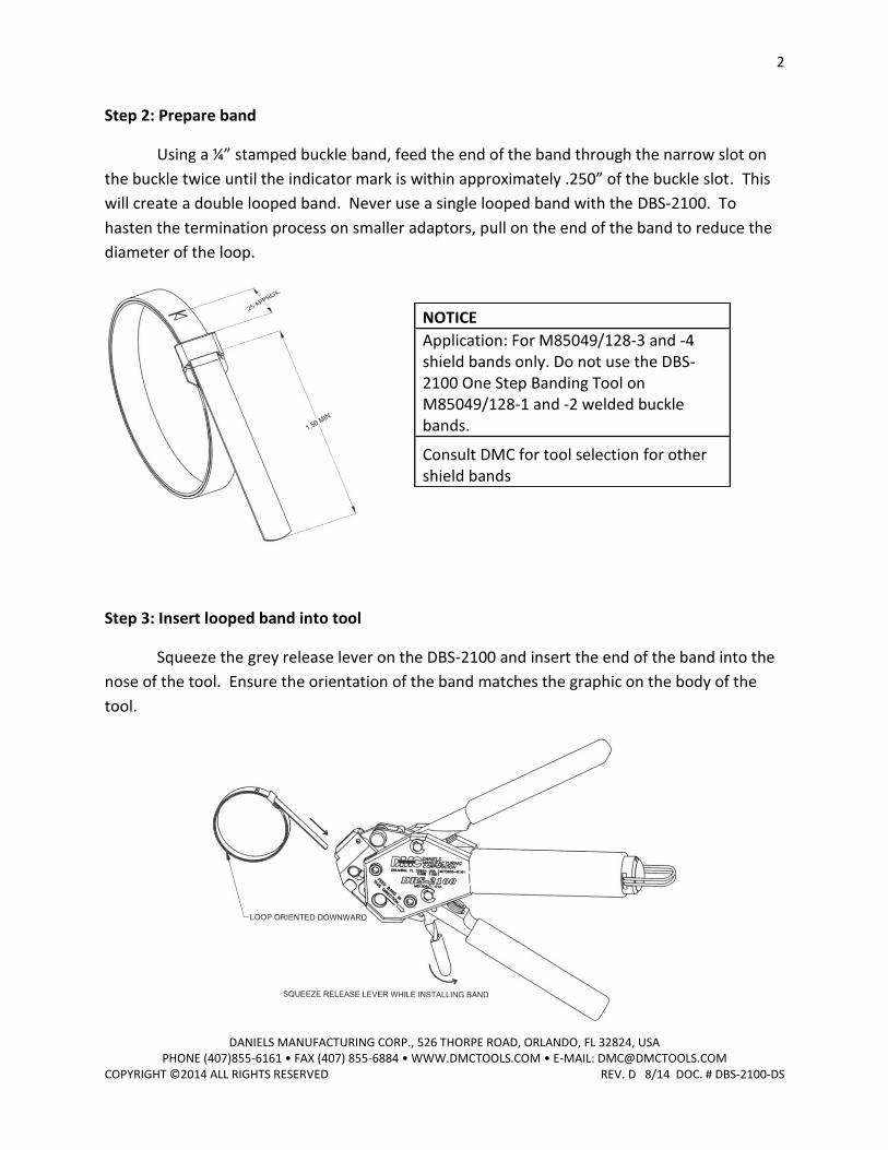
Step 2: Prepare band
Using a ¼” stamped buckle band, feed the end of the band through the narrow slot on
the buckle twice until the indicator mark is within approximately .250” of the buckle slot. This
will create a double looped band. Never use a single looped band with the DBS-2100. To
hasten the termination process on smaller adaptors, pull on the end of the band to reduce the
diameter of the loop.
Step 3: Insert looped band into tool
Squeeze the grey release lever on the DBS-2100 and insert the end of the band into the
nose of the tool. Ensure the orientation of the band matches the graphic on the body of the
tool.
NOTICE
Application: For M85049/128-3 and -4 shield bands only. Do not use the DBS-2100 One Step Banding Tool on M85049/128-1 and -2 welded buckle bands.
Consult DMC for tool selection for other shield bands
3
DANIELS MANUFACTURING CORP., 526 THORPE ROAD, ORLANDO, FL 32824, USA PHONE (407)855-6161 • FAX (407) 855-6884 • WWW.DMCTOOLS.COM • E-MAIL: [email protected]
COPYRIGHT ©2014 ALL RIGHTS RESERVED REV. D 8/14 DOC. # DBS-2100-DS
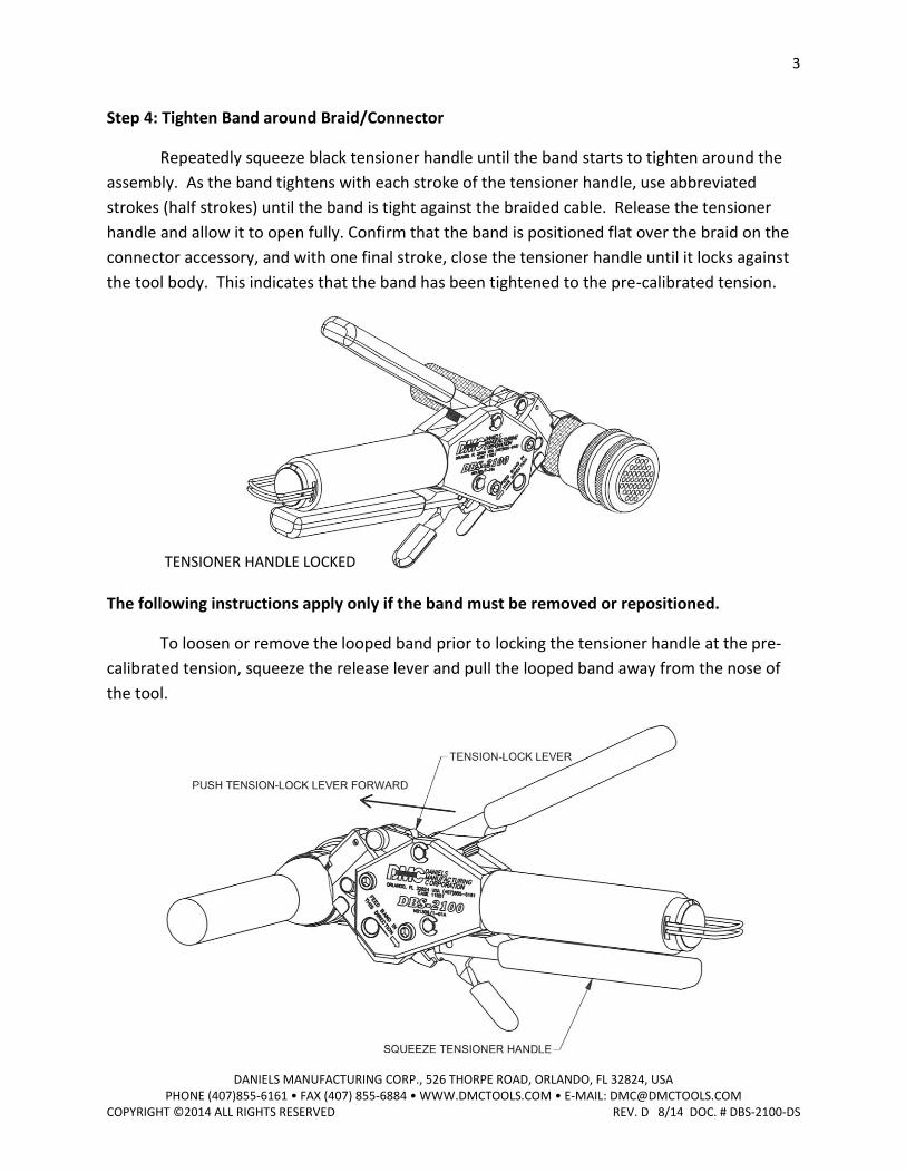
Step 4: Tighten Band around Braid/Connector
Repeatedly squeeze black tensioner handle until the band starts to tighten around the
assembly. As the band tightens with each stroke of the tensioner handle, use abbreviated
strokes (half strokes) until the band is tight against the braided cable. Release the tensioner
handle and allow it to open fully. Confirm that the band is positioned flat over the braid on the
connector accessory, and with one final stroke, close the tensioner handle until it locks against
the tool body. This indicates that the band has been tightened to the pre-calibrated tension.
The following instructions apply only if the band must be removed or repositioned.
To loosen or remove the looped band prior to locking the tensioner handle at the pre-
calibrated tension, squeeze the release lever and pull the looped band away from the nose of
the tool.
TENSIONER HANDLE LOCKED
4
DANIELS MANUFACTURING CORP., 526 THORPE ROAD, ORLANDO, FL 32824, USA PHONE (407)855-6161 • FAX (407) 855-6884 • WWW.DMCTOOLS.COM • E-MAIL: [email protected]
COPYRIGHT ©2014 ALL RIGHTS RESERVED REV. D 8/14 DOC. # DBS-2100-DS
To loosen or remove the looped band after locking the tensioner handle at the pre-
calibrated tension, squeeze the tensioner handle and push the tension-lock lever forward.
While holding the tension-lock lever forward, release the tensioner handle. The tensioner
handle will open fully. Squeeze the release lever and pull the looped band away from the nose
of the tool.
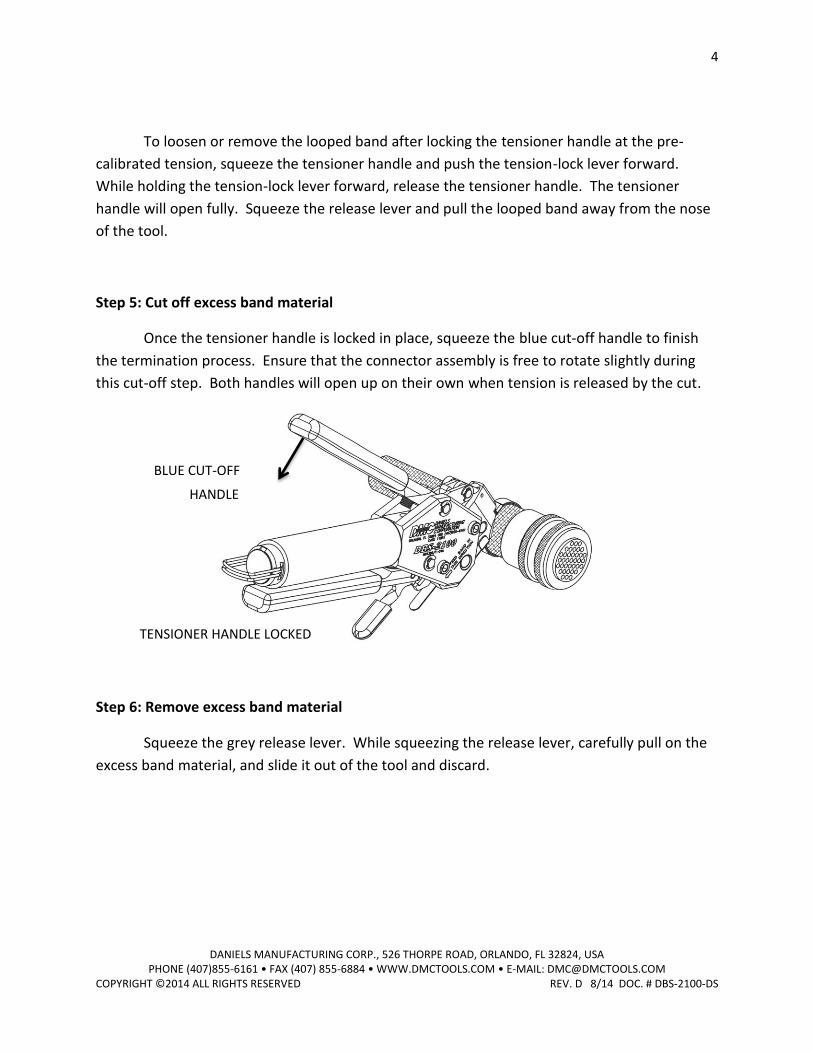
Step 5: Cut off excess band material
Once the tensioner handle is locked in place, squeeze the blue cut-off handle to finish
the termination process. Ensure that the connector assembly is free to rotate slightly during
this cut-off step. Both handles will open up on their own when tension is released by the cut.
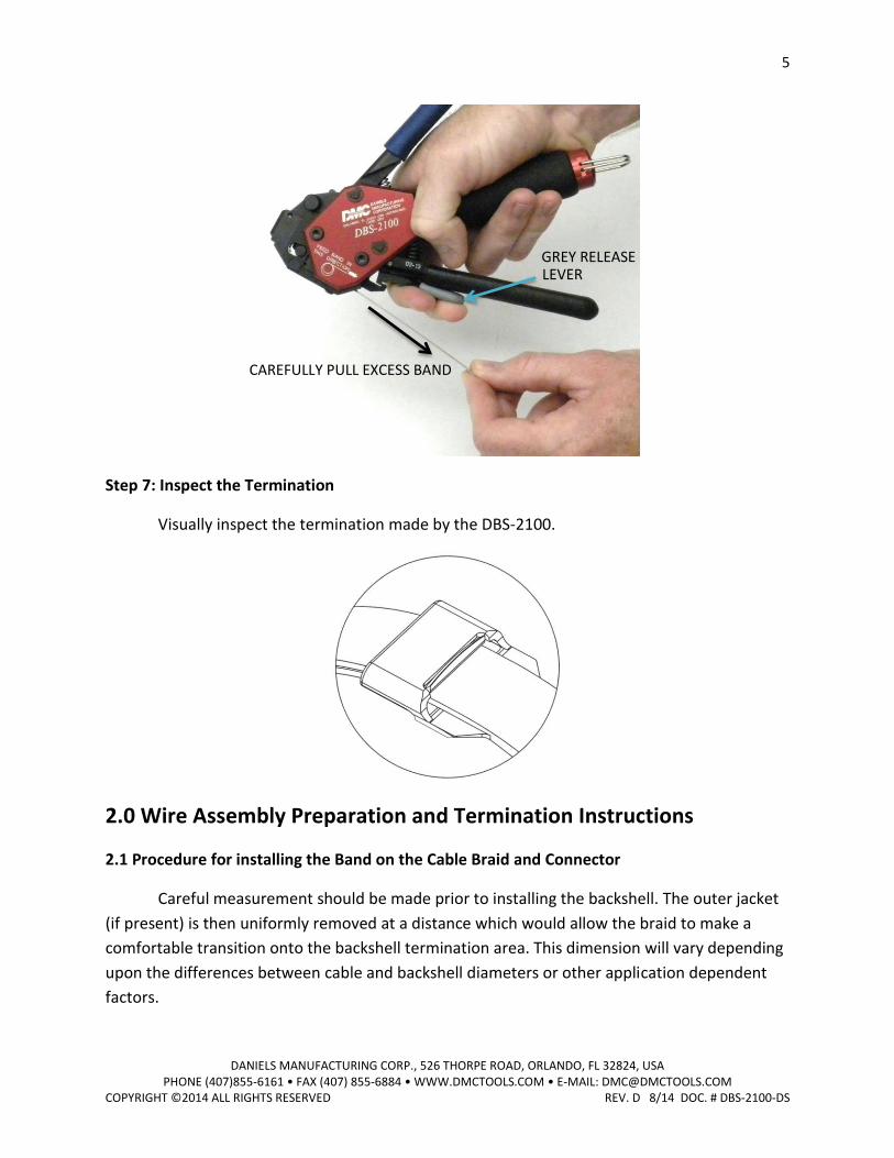
Step 6: Remove excess band material
Squeeze the grey release lever. While squeezing the release lever, carefully pull on the
excess band material, and slide it out of the tool and discard.
BLUE CUT-OFF
HANDLE
TENSIONER HANDLE LOCKED
5
DANIELS MANUFACTURING CORP., 526 THORPE ROAD, ORLANDO, FL 32824, USA PHONE (407)855-6161 • FAX (407) 855-6884 • WWW.DMCTOOLS.COM • E-MAIL: [email protected]
COPYRIGHT ©2014 ALL RIGHTS RESERVED REV. D 8/14 DOC. # DBS-2100-DS
Step 7: Inspect the Termination
Visually inspect the termination made by the DBS-2100.
2.0 Wire Assembly Preparation and Termination Instructions
2.1 Procedure for installing the Band on the Cable Braid and Connector
Careful measurement should be made prior to installing the backshell. The outer jacket
(if present) is then uniformly removed at a distance which would allow the braid to make a
comfortable transition onto the backshell termination area. This dimension will vary depending
upon the differences between cable and backshell diameters or other application dependent
factors.
GREY RELEASE LEVER
CAREFULLY PULL EXCESS BAND
6
DANIELS MANUFACTURING CORP., 526 THORPE ROAD, ORLANDO, FL 32824, USA PHONE (407)855-6161 • FAX (407) 855-6884 • WWW.DMCTOOLS.COM • E-MAIL: [email protected]
COPYRIGHT ©2014 ALL RIGHTS RESERVED REV. D 8/14 DOC. # DBS-2100-DS
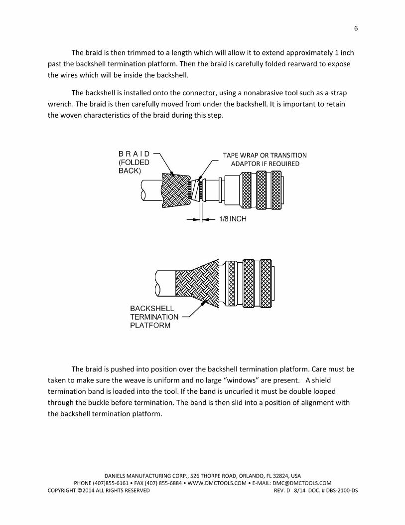
The braid is then trimmed to a length which will allow it to extend approximately 1 inch
past the backshell termination platform. Then the braid is carefully folded rearward to expose
the wires which will be inside the backshell.
The backshell is installed onto the connector, using a nonabrasive tool such as a strap
wrench. The braid is then carefully moved from under the backshell. It is important to retain
the woven characteristics of the braid during this step.
The braid is pushed into position over the backshell termination platform. Care must be
taken to make sure the weave is uniform and no large “windows” are present. A shield
termination band is loaded into the tool. If the band is uncurled it must be double looped
through the buckle before termination. The band is then slid into a position of alignment with
the backshell termination platform.
ADAPTOR IF REQUIRED TAPE WRAP OR TRANSITION
7
DANIELS MANUFACTURING CORP., 526 THORPE ROAD, ORLANDO, FL 32824, USA PHONE (407)855-6161 • FAX (407) 855-6884 • WWW.DMCTOOLS.COM • E-MAIL: [email protected]
COPYRIGHT ©2014 ALL RIGHTS RESERVED REV. D 8/14 DOC. # DBS-2100-DS
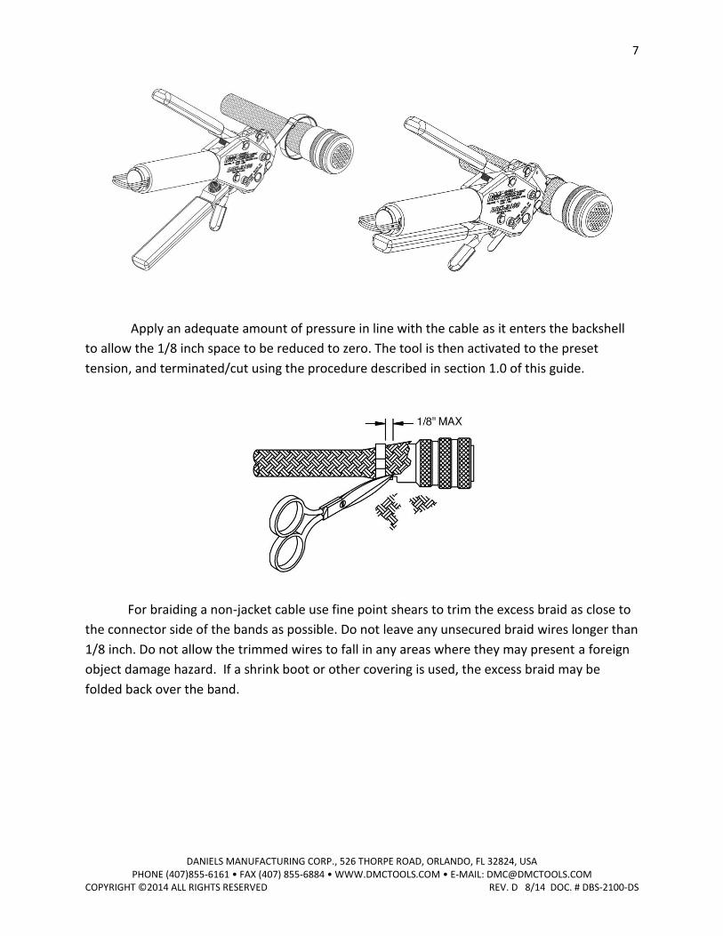
Apply an adequate amount of pressure in line with the cable as it enters the backshell
to allow the 1/8 inch space to be reduced to zero. The tool is then activated to the preset
tension, and terminated/cut using the procedure described in section 1.0 of this guide.
For braiding a non-jacket cable use fine point shears to trim the excess braid as close to
the connector side of the bands as possible. Do not leave any unsecured braid wires longer than
1/8 inch. Do not allow the trimmed wires to fall in any areas where they may present a foreign
object damage hazard. If a shrink boot or other covering is used, the excess braid may be
folded back over the band.
8
DANIELS MANUFACTURING CORP., 526 THORPE ROAD, ORLANDO, FL 32824, USA PHONE (407)855-6161 • FAX (407) 855-6884 • WWW.DMCTOOLS.COM • E-MAIL: [email protected]
COPYRIGHT ©2014 ALL RIGHTS RESERVED REV. D 8/14 DOC. # DBS-2100-DS
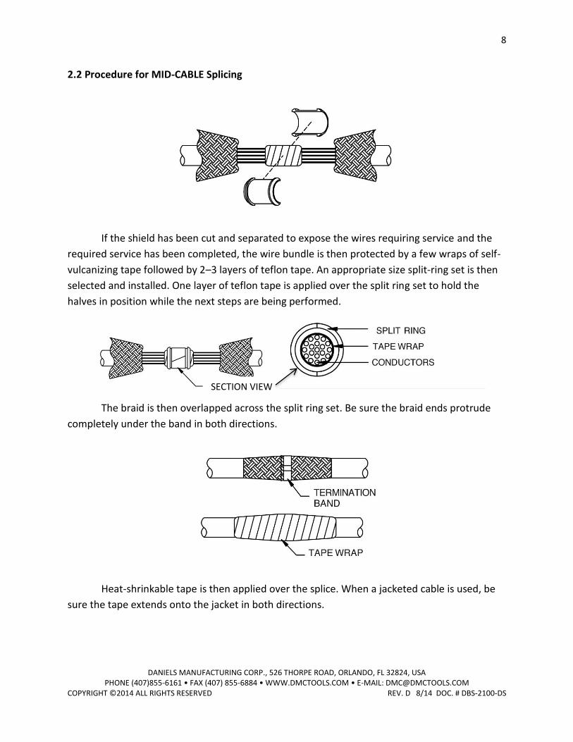
2.2 Procedure for MID-CABLE Splicing
If the shield has been cut and separated to expose the wires requiring service and the
required service has been completed, the wire bundle is then protected by a few wraps of self-
vulcanizing tape followed by 2–3 layers of teflon tape. An appropriate size split-ring set is then
selected and installed. One layer of teflon tape is applied over the split ring set to hold the
halves in position while the next steps are being performed.
The braid is then overlapped across the split ring set. Be sure the braid ends protrude
completely under the band in both directions.
Heat-shrinkable tape is then applied over the splice. When a jacketed cable is used, be
sure the tape extends onto the jacket in both directions.
SECTION VIEW
9
DANIELS MANUFACTURING CORP., 526 THORPE ROAD, ORLANDO, FL 32824, USA PHONE (407)855-6161 • FAX (407) 855-6884 • WWW.DMCTOOLS.COM • E-MAIL: [email protected]
COPYRIGHT ©2014 ALL RIGHTS RESERVED REV. D 8/14 DOC. # DBS-2100-DS
3.0 BAND TENSION VERIFICATION
INTRODUCTION
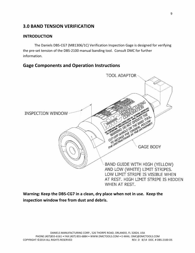
The Daniels DBS-CG7 (M81306/1C) Verification Inspection Gage is designed for verifying
the pre-set tension of the DBS-2100 manual banding tool. Consult DMC for further
information.
Gage Components and Operation Instructions
Warning: Keep the DBS-CG7 in a clean, dry place when not in use. Keep the
inspection window free from dust and debris.
10
DANIELS MANUFACTURING CORP., 526 THORPE ROAD, ORLANDO, FL 32824, USA PHONE (407)855-6161 • FAX (407) 855-6884 • WWW.DMCTOOLS.COM • E-MAIL: [email protected]
COPYRIGHT ©2014 ALL RIGHTS RESERVED REV. D 8/14 DOC. # DBS-2100-DS
3.1 VERIFYING THE TENSION APPLIED TO THE BAND IS WITHIN 145-155 POUNDS.
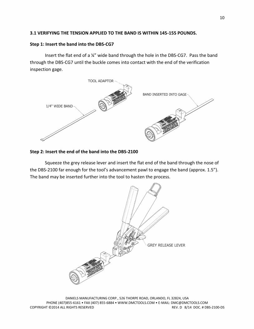
Step 1: Insert the band into the DBS-CG7
Insert the flat end of a ¼” wide band through the hole in the DBS-CG7. Pass the band
through the DBS-CG7 until the buckle comes into contact with the end of the verification
inspection gage.
Step 2: Insert the end of the band into the DBS-2100
Squeeze the grey release lever and insert the flat end of the band through the nose of
the DBS-2100 far enough for the tool’s advancement pawl to engage the band (approx. 1.5”).
The band may be inserted further into the tool to hasten the process.
11
DANIELS MANUFACTURING CORP., 526 THORPE ROAD, ORLANDO, FL 32824, USA PHONE (407)855-6161 • FAX (407) 855-6884 • WWW.DMCTOOLS.COM • E-MAIL: [email protected]
COPYRIGHT ©2014 ALL RIGHTS RESERVED REV. D 8/14 DOC. # DBS-2100-DS
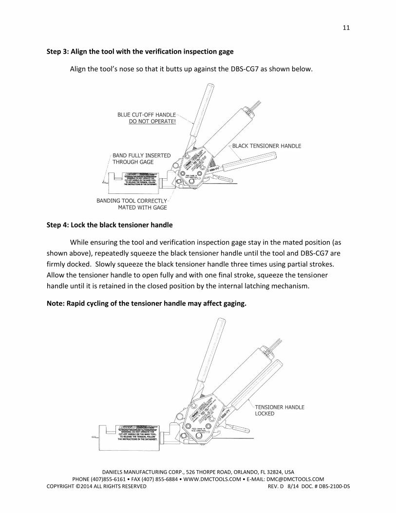
Step 3: Align the tool with the verification inspection gage
Align the tool’s nose so that it butts up against the DBS-CG7 as shown below.
Step 4: Lock the black tensioner handle
While ensuring the tool and verification inspection gage stay in the mated position (as
shown above), repeatedly squeeze the black tensioner handle until the tool and DBS-CG7 are
firmly docked. Slowly squeeze the black tensioner handle three times using partial strokes.
Allow the tensioner handle to open fully and with one final stroke, squeeze the tensioner
handle until it is retained in the closed position by the internal latching mechanism.
Note: Rapid cycling of the tensioner handle may affect gaging.
12
DANIELS MANUFACTURING CORP., 526 THORPE ROAD, ORLANDO, FL 32824, USA PHONE (407)855-6161 • FAX (407) 855-6884 • WWW.DMCTOOLS.COM • E-MAIL: [email protected]
COPYRIGHT ©2014 ALL RIGHTS RESERVED REV. D 8/14 DOC. # DBS-2100-DS
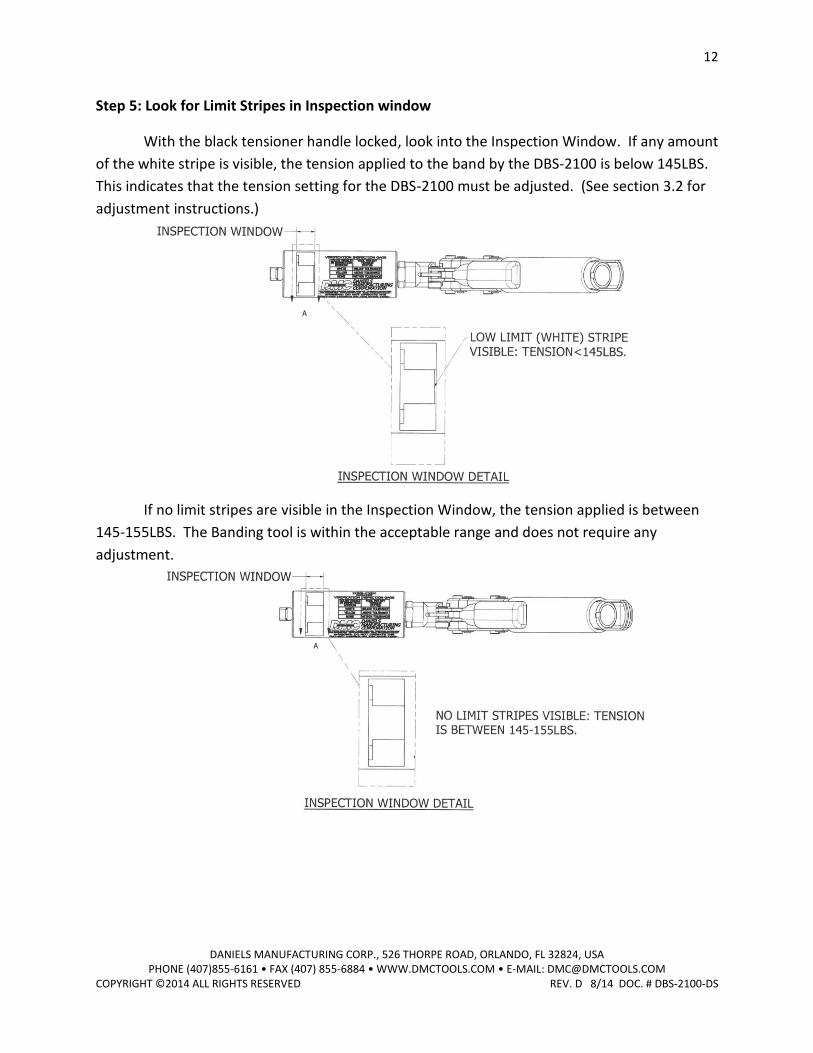
Step 5: Look for Limit Stripes in Inspection window
With the black tensioner handle locked, look into the Inspection Window. If any amount
of the white stripe is visible, the tension applied to the band by the DBS-2100 is below 145LBS.
This indicates that the tension setting for the DBS-2100 must be adjusted. (See section 3.2 for
adjustment instructions.)
If no limit stripes are visible in the Inspection Window, the tension applied is between
145-155LBS. The Banding tool is within the acceptable range and does not require any
adjustment.
13
DANIELS MANUFACTURING CORP., 526 THORPE ROAD, ORLANDO, FL 32824, USA PHONE (407)855-6161 • FAX (407) 855-6884 • WWW.DMCTOOLS.COM • E-MAIL: [email protected]
COPYRIGHT ©2014 ALL RIGHTS RESERVED REV. D 8/14 DOC. # DBS-2100-DS
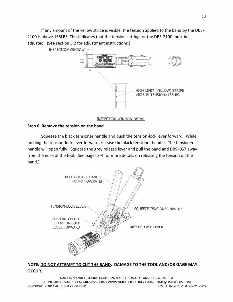
If any amount of the yellow stripe is visible, the tension applied to the band by the DBS-
2100 is above 155LBS. This indicates that the tension setting for the DBS-2100 must be
adjusted. (See section 3.2 for adjustment instructions.)
Step 6: Remove the tension on the band
Squeeze the black tensioner handle and push the tension-lock lever forward. While
holding the tension-lock lever forward, release the black tensioner handle. The tensioner
handle will open fully. Squeeze the grey release lever and pull the band and DBS-CG7 away
from the nose of the tool. (See pages 3-4 for more details on releasing the tension on the
band.)
NOTE: DO NOT ATTEMPT TO CUT THE BAND. DAMAGE TO THE TOOL AND/OR GAGE MAY
OCCUR.
14
DANIELS MANUFACTURING CORP., 526 THORPE ROAD, ORLANDO, FL 32824, USA PHONE (407)855-6161 • FAX (407) 855-6884 • WWW.DMCTOOLS.COM • E-MAIL: [email protected]
COPYRIGHT ©2014 ALL RIGHTS RESERVED REV. D 8/14 DOC. # DBS-2100-DS
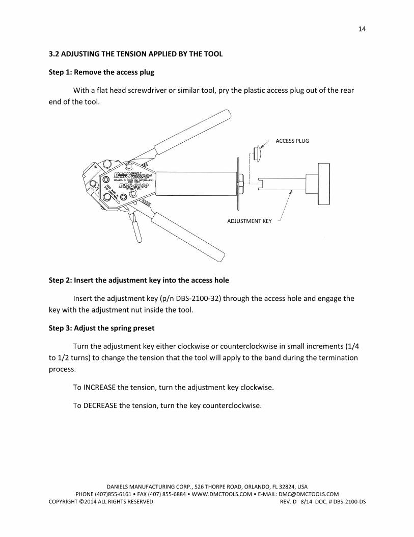
3.2 ADJUSTING THE TENSION APPLIED BY THE TOOL
Step 1: Remove the access plug
With a flat head screwdriver or similar tool, pry the plastic access plug out of the rear
end of the tool.
Step 2: Insert the adjustment key into the access hole
Insert the adjustment key (p/n DBS-2100-32) through the access hole and engage the
key with the adjustment nut inside the tool.
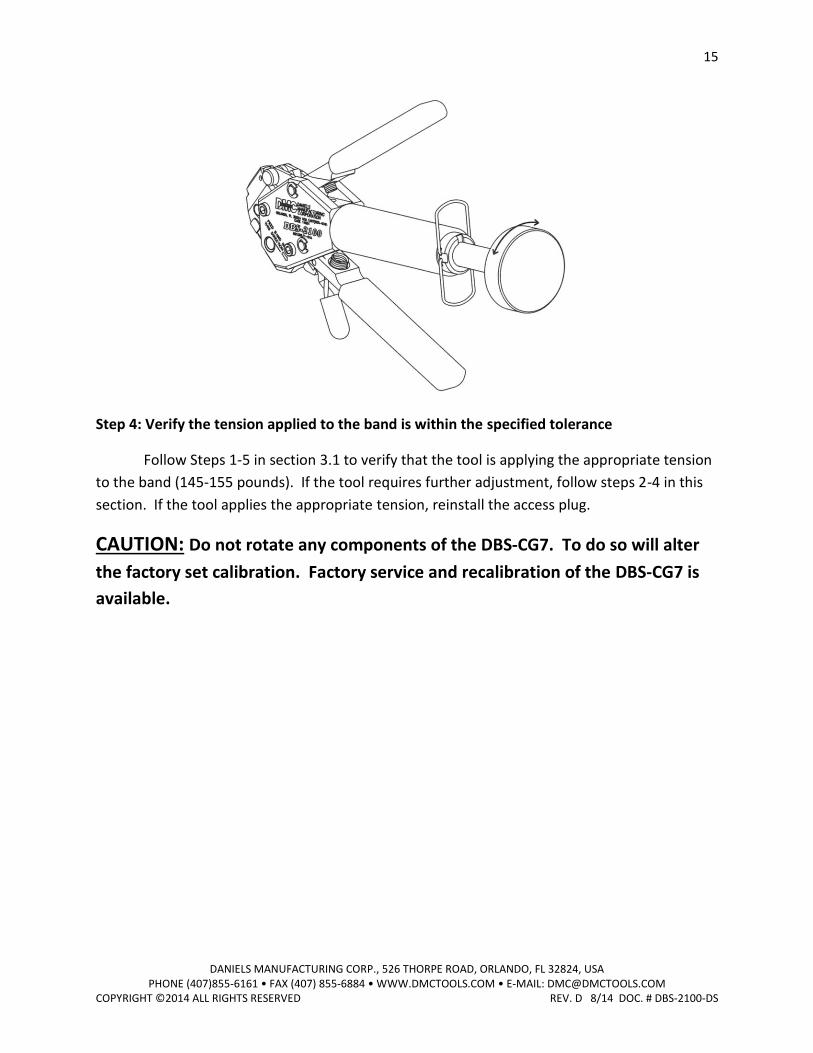
Step 3: Adjust the spring preset
Turn the adjustment key either clockwise or counterclockwise in small increments (1/4
to 1/2 turns) to change the tension that the tool will apply to the band during the termination
process.
To INCREASE the tension, turn the adjustment key clockwise.
To DECREASE the tension, turn the key counterclockwise.
ADJUSTMENT KEY
ACCESS PLUG
15
DANIELS MANUFACTURING CORP., 526 THORPE ROAD, ORLANDO, FL 32824, USA PHONE (407)855-6161 • FAX (407) 855-6884 • WWW.DMCTOOLS.COM • E-MAIL: [email protected]
COPYRIGHT ©2014 ALL RIGHTS RESERVED REV. D 8/14 DOC. # DBS-2100-DS
Step 4: Verify the tension applied to the band is within the specified tolerance
Follow Steps 1-5 in section 3.1 to verify that the tool is applying the appropriate tension
to the band (145-155 pounds). If the tool requires further adjustment, follow steps 2-4 in this
section. If the tool applies the appropriate tension, reinstall the access plug.
CAUTION: Do not rotate any components of the DBS-CG7. To do so will alter
the factory set calibration. Factory service and recalibration of the DBS-CG7 is
available.
16
DANIELS MANUFACTURING CORP., 526 THORPE ROAD, ORLANDO, FL 32824, USA PHONE (407)855-6161 • FAX (407) 855-6884 • WWW.DMCTOOLS.COM • E-MAIL: [email protected]
COPYRIGHT ©2014 ALL RIGHTS RESERVED REV. D 8/14 DOC. # DBS-2100-DS
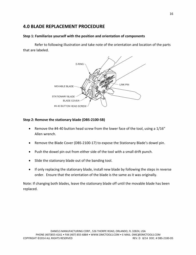
4.0 BLADE REPLACEMENT PROCEDURE
Step 1: Familiarize yourself with the position and orientation of components
Refer to following illustration and take note of the orientation and location of the parts
that are labeled.
Step 2: Remove the stationary blade (DBS-2100-SB)
Remove the #4-40 button head screw from the lower face of the tool, using a 1/16”
Allen wrench.
Remove the Blade Cover (DBS-2100-17) to expose the Stationary Blade’s dowel pin.
Push the dowel pin out from either side of the tool with a small drift punch.
Slide the stationary blade out of the banding tool.
If only replacing the stationary blade, install new blade by following the steps in reverse
order. Ensure that the orientation of the blade is the same as it was originally.
Note: If changing both blades, leave the stationary blade off until the movable blade has been
replaced.
17
DANIELS MANUFACTURING CORP., 526 THORPE ROAD, ORLANDO, FL 32824, USA PHONE (407)855-6161 • FAX (407) 855-6884 • WWW.DMCTOOLS.COM • E-MAIL: [email protected]
COPYRIGHT ©2014 ALL RIGHTS RESERVED REV. D 8/14 DOC. # DBS-2100-DS
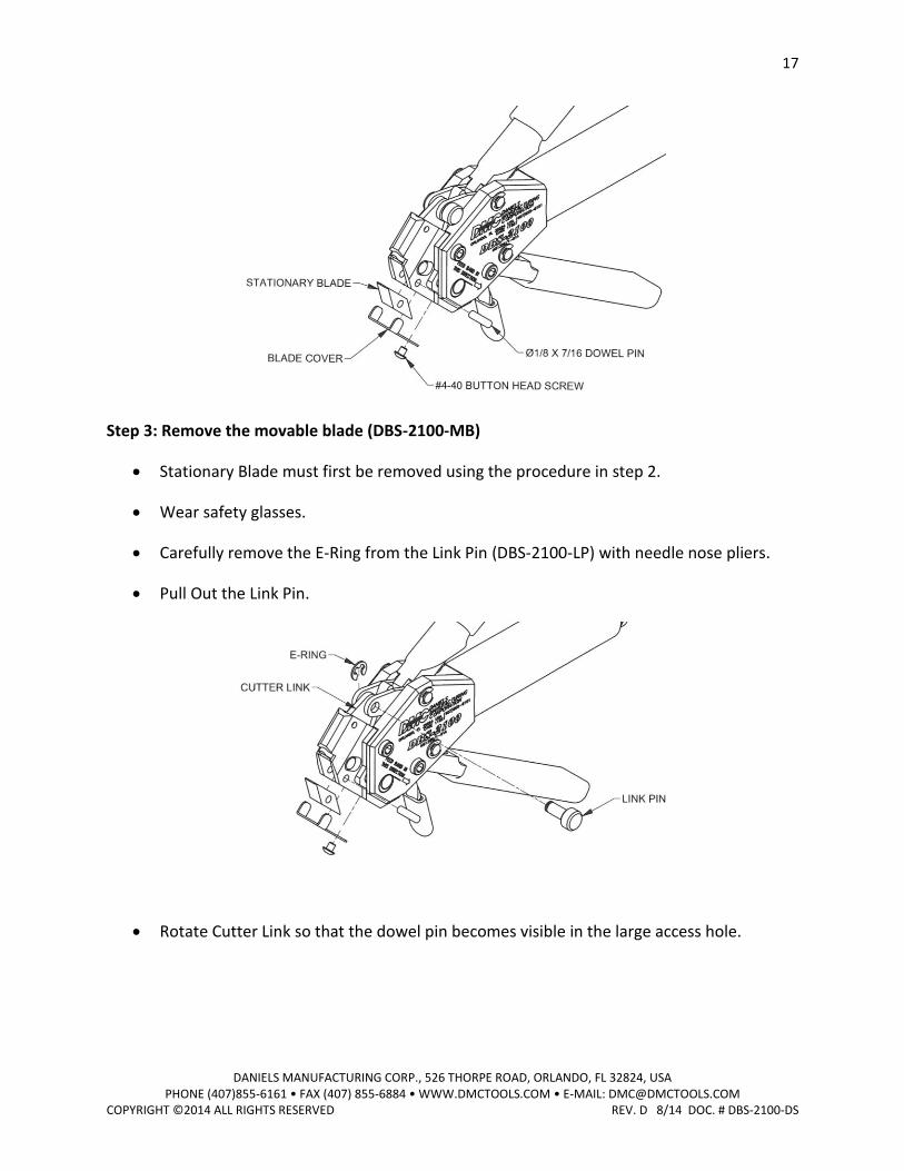
Step 3: Remove the movable blade (DBS-2100-MB)
Stationary Blade must first be removed using the procedure in step 2.
Wear safety glasses.
Carefully remove the E-Ring from the Link Pin (DBS-2100-LP) with needle nose pliers.
Pull Out the Link Pin.
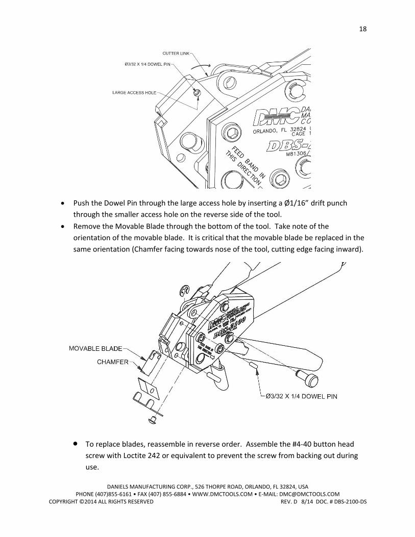
Rotate Cutter Link so that the dowel pin becomes visible in the large access hole.
18
DANIELS MANUFACTURING CORP., 526 THORPE ROAD, ORLANDO, FL 32824, USA PHONE (407)855-6161 • FAX (407) 855-6884 • WWW.DMCTOOLS.COM • E-MAIL: [email protected]
COPYRIGHT ©2014 ALL RIGHTS RESERVED REV. D 8/14 DOC. # DBS-2100-DS
Push the Dowel Pin through the large access hole by inserting a Ø1/16” drift punch
through the smaller access hole on the reverse side of the tool.
Remove the Movable Blade through the bottom of the tool. Take note of the
orientation of the movable blade. It is critical that the movable blade be replaced in the
same orientation (Chamfer facing towards nose of the tool, cutting edge facing inward).
To replace blades, reassemble in reverse order. Assemble the #4-40 button head
screw with Loctite 242 or equivalent to prevent the screw from backing out during
use.
19
DANIELS MANUFACTURING CORP., 526 THORPE ROAD, ORLANDO, FL 32824, USA PHONE (407)855-6161 • FAX (407) 855-6884 • WWW.DMCTOOLS.COM • E-MAIL: [email protected]
COPYRIGHT ©2014 ALL RIGHTS RESERVED REV. D 8/14 DOC. # DBS-2100-DS
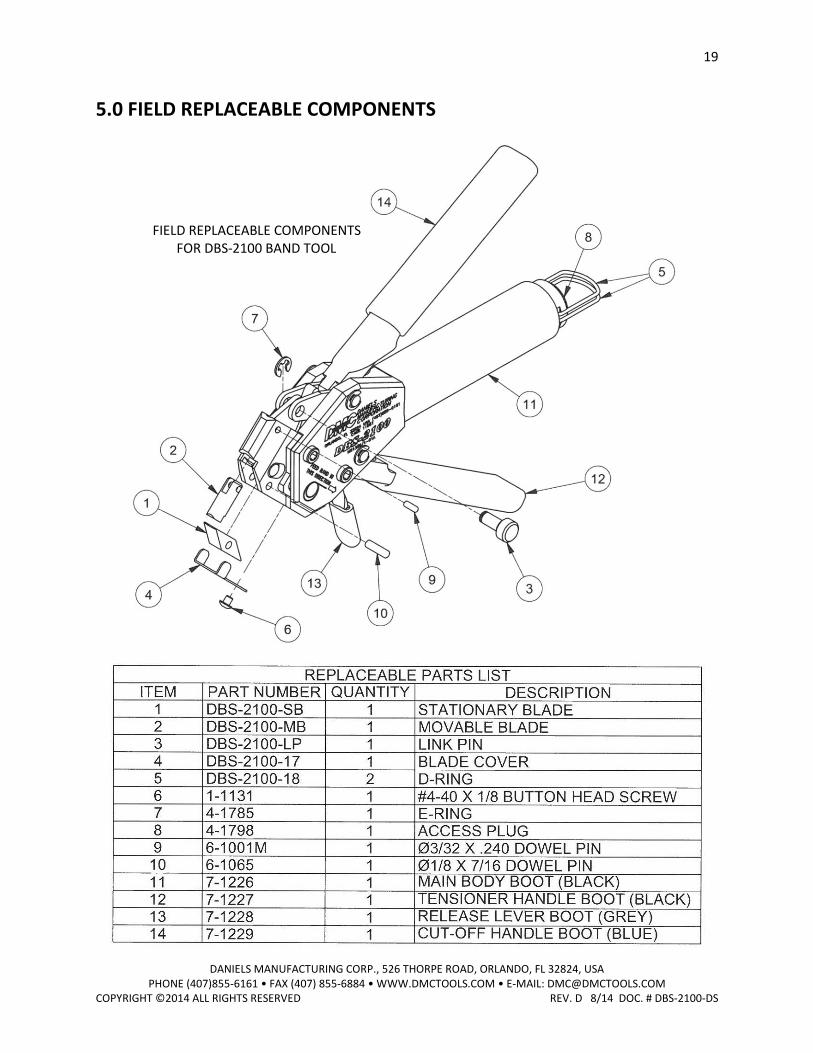
5.0 FIELD REPLACEABLE COMPONENTS
FIELD REPLACEABLE COMPONENTS FOR DBS-2100 BAND TOOL

20
DANIELS MANUFACTURING CORP., 526 THORPE ROAD, ORLANDO, FL 32824, USA PHONE (407)855-6161 • FAX (407) 855-6884 • WWW.DMCTOOLS.COM • E-MAIL: [email protected]
COPYRIGHT ©2014 ALL RIGHTS RESERVED REV. D 8/14 DOC. # DBS-2100-DS
Daniels Manufacturing Corporation offers complete refurbishing and recalibration services.
DMC specially engineers and manufactures complete tool kits to satisfy individual customer
requirements, such as total aircraft support, general shop maintenance or production, on board
ship and vehicle service, etc.
LIMITATION OF LIABILITY
Daniels Manufacturing Corporation is not liable for consequential or special damages of any
nature or kind resulting from the use, or misuse, of any of its products. Owners and users of
DMC products assume full responsibility for instructing their employees in the proper and safe
use of such products.
LIMITED WARRANTY
DMC (Daniels Manufacturing Corporation) warrants each new product sold by it to be free from
defects in material and workmanship under normal use and service. DMC's obligation under
this warranty is limited to the free correction or, at DMC's option, the refund of the purchase
price of any such product which proves defective in normal service within ninety (90) days after
delivery to the first user, provided that the product is returned to DMC with transportation
charges prepaid and which shall appear to DMC's satisfaction, it being understood that DMC
products are not consumer products. This warranty shall not cover any damage to any product
which, in the opinion of DMC, was caused by normal wear, misuse, improper operation,
tampering, neglect or accident. This warranty is in lieu of all other warranties express or
implied. No warranty, express or implied, is made or authorized to be made or assumed with
respect to products of Daniels Manufacturing Corporation other than those herein set forth.

Mouser Electronics
Authorized Distributor
Click to View Pricing, Inventory, Delivery & Lifecycle Information: Daniels Manufacturing:
DBS-2100