Embed Size (px)
Citation preview

10” PLANER / THICKNESSERMODEL NO: CPT1000
PART NO: 6500870
OPERATION & MAINTENANCEINSTRUCTIONS
LS0914

P
INTRODUCTION
Thank you for purchasing this CLARKE product.
Before attempting to use this product, please read this manual thoroughly and follow the instructions carefully. In doing so you will ensure the safety of yourself and that of others around you, and you can look forward to your purchase giving you long and satisfactory service.
GUARANTEE
This product is guaranteed against faulty manufacture for a period of 12 months from the date of purchase. Please keep your receipt which will be required as proof of purchase.
This guarantee is invalid if the product is found to have been abused or tampered with in any way, or not used for the purpose for which it was intended.
Faulty goods should be returned to their place of purchase, no product can be returned to us without prior permission.
This guarantee does not effect your statutory rights.
CONTENTS
The following items should be supplied in the carton. If any parts are missing, do not operate until the missing parts are replaced. Failure to follow this rule could result in serious injury.
1 x 10 inch Planer / Thicknesser 2 x Spare Drive Belt
1 x Angle Fence assembly 1 x 4mm Hexagon Key
1 x Dust Chute assembly 1 x Push-stick
1 x Table Elevating Handle 1 x Instruction Manual
2arts & Service: 020 8988 7400 / E-mail: [email protected] or [email protected]

P
SAFETY WARNINGS
1. Read and understand the entire owner's manual before attempting assembly or operation.
2. Read and understand the warnings posted on the machine and in this manual. Failure to comply with all of these warnings may cause serious injury.
3. Replace the warning labels if they become obscured or removed.
4. This planer/thicknesser is designed and intended for use by properly trained and experienced personnel only. If you are not familiar with the proper and safe operation of a planer/thicknesser, do not use until proper training and knowledge have been obtained.
5. Do not use this for other than its intended use.
6. Always wear approved safety glasses/face shields while using this planer/thicknesser. Everyday eyeglasses only have impact resistant lenses; they are not safety glasses.
7. Before operating this planer/thicknesser, remove tie, rings, watches and other jewelry, and roll sleeves up past the elbows. Remove all loose clothing and confine long hair. Non-slip footwear or anti-skid floor strips are recommended. Do not wear gloves.
8. Wear ear protectors (plugs or muffs) during extended periods of operation.
9. Some dust created by power sanding, sawing, grinding, drilling and other construction activities contain chemicals known to cause cancer, birth defects or other reproductive harm. Some examples of these chemicals are:
• Lead from lead based paint.
• Crystalline silica from bricks, cement and other masonry products.
• Arsenic and chromium from chemically treated lumber.
Your risk of exposure varies, depending on how often you do this type of work. To reduce your exposure to these chemicals, work in a well-ventilated area and work with approved safety equipment, such as face or dust masks that are specifically designed to filter out microscopic particles.
10. Do not operate this machine while tired or under the influence of drugs, alcohol or any medication.
11. Make certain the switch is in the OFF position before connecting the machine to the power source.
12. Make certain the machine is properly grounded.
13. Make all machine adjustments or maintenance with the machine unplugged from the power source.
14. Remove adjusting keys and wrenches. Form a habit of checking to see that keys and adjusting wrenches are removed from the machine before turning it on.
3arts & Service: 020 8988 7400 / E-mail: [email protected] or [email protected]

P
15. Keep safety guards in place at all times when the machine is in use. If removed for maintenance purposes, use extreme caution and replace the guards immediately.
16. Make sure the planer/thicknesser is firmly secured to the floor or bench before use.
17. Check damaged parts. Before further use of the machine, a guard or other part that is damaged should be carefully checked to determine that it will operate properly and perform its intended function. Check for alignment of moving parts, binding of moving parts, breakage of parts, mounting and any other conditions that may affect its operation. A guard or other part that is damaged should be properly repaired or replaced.
18. Provide for adequate space surrounding work area and non-glare, overhead lighting.
19. Keep the floor around the machine clean and free of scrap material, oil and grease.
20. Keep visitors a safe distance from the work area. Keep children away.
21. Make your workshop child proof with padlocks, master switches or by removing starter keys.
22. Give your work undivided attention. Looking around, carrying on a conversation and “horse-play” are careless acts that can result in serious injury.
23. Maintain a balanced stance at all times so that you do not fall or lean against the cutterhead or other
moving parts. Do not overreach or use excessive force to perform any machine operation.
24. Use the right tool at the correct speed and feed rate. Do not force a tool or attachment to do a job for which it was not designed. The right tool will do the job better and safer.
25. Use recommended accessories; improper accessories may be hazardous.
26. Maintain tools with care. Keep knives sharp and clean for the best and safest performance. Follow instructions for lubricating and changing accessories.
27. Turn off the machine before cleaning. Use a brush or compressed air to remove chips or debris — do not use your hands.
28. Do not stand on the machine. Serious injury could occur if the machine tips over.
29. Never leave the machine running unattended. Turn the power off and do not leave the machine until it comes to a complete stop.
30. Before turning on machine, remove all extra equipment such as keys, wrenches, scrap, stock, and cleaning rags away from the machine.
31. Always use a hold-down or push block when surfacing stock less than 300mm inches long, or 75mm wide, or 75mm thick.
32. Do not perform edge jointing operations on material shorter than 150mm, narrower than 18mm or less than 6mm thick.
4arts & Service: 020 8988 7400 / E-mail: [email protected] or [email protected]
P
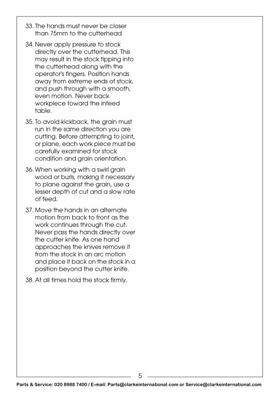
33. The hands must never be closer than 75mm to the cutterhead
34. Never apply pressure to stock directly over the cutterhead. This may result in the stock tipping into the cutterhead along with the operator's fingers. Position hands away from extreme ends of stock, and push through with a smooth, even motion. Never back workpiece toward the infeed table.
35. To avoid kickback, the grain must run in the same direction you are cutting. Before attempting to joint, or plane, each work piece must be carefully examined for stock condition and grain orientation.
36. When working with a swirl grain wood or burls, making it necessary to plane against the grain, use a lesser depth of cut and a slow rate of feed.
37. Move the hands in an alternate motion from back to front as the work continues through the cut. Never pass the hands directly over the cutter knife. As one hand approaches the knives remove it from the stock in an arc motion and place it back on the stock in a position beyond the cutter knife.
38. At all times hold the stock firmly.
5arts & Service: 020 8988 7400 / E-mail: [email protected] or [email protected]

P
SAFETY SYMBOLS::
Read this instruction booklet carefully before positioning, operating or adjusting the machine.
Wear eye protection
Wear ear protection
Wear a dust mask that is specially designed to filter microscopic particles.
CAUTION: THIS MEANS THAT IF PRECAUTIONS ARE NOT HEEDED, IT MAY RESULT IN MINOR INJURY AND/OR POSSIBLE MACHINE DAMAGE.
WARNING: THIS MEANS THAT IF PRECAUTIONS ARE NOT HEEDED, IT MAY RESULT IN SERIOUS INJURY
6arts & Service: 020 8988 7400 / E-mail: [email protected] or [email protected]

7Parts & Service: 020 8988 7400 / E-mail: [email protected] or [email protected]
ELECTRICAL CONNECTIONS
Connect the mains lead to a standard, 230 Volt (50Hz) electrical supply through an approved 13 amp BS 1363 plug, or a suitably fused isolator switch.
If the plug has to be changed because it is not suitable for your socket, or because of damage, it must be removed and a replacement fitted, following the wiring instructions shown below. The old plug must be discarded safely, as insertion into a power socket could cause an electrical hazard.
If the colours of the wires in the power cable do not agree with the markings on the plug.
• The BLUE wire must be connected to the terminal which is marked N or coloured black.
• The BROWN wire must be connected to the terminal which is marked L or coloured red.
• The YELLOW AND GREEN wire must be connected to the terminal which is marked E or or coloured green.
We strongly recommend that this machine is connected to the mains supply through a Residual Current Device (RCD)If you are not sure, consult a qualified electrician. DO NOT try to do any repairs.
WARNING: READ THESE ELECTRICAL SAFETY INSTRUCTIONS THOROUGHLY BEFORE CONNECTING THE PRODUCT TO THE MAINS SUPPLY.
WARNING: THE WIRES IN THE POWER CABLE OF THIS PRODUCT ARE COLOURED IN ACCORDANCE WITH THE FOLLOWING CODE:BLUE = NEUTRAL BROWN = LIVE YELLOW AND GREEN = EARTH
Plug must be BS1363/A approved.
Always fit
Ensure that the outer sheath of
Neutral(Blue)
Live(Brown)
Earth(Green and
a 13 Amp
the cable is firmly held by the clamp
fuse.
Yellow)

P
PLANER SETUP
FITTING THE FENCE1. Position the fence as shown.
2. Lock the fence in place using the two hexagon screws supplied.
FENCE POSITION ADJUSTMENT
1. Move the fence position lock downward to release the fence
2. Slide the fence to the required position
3. Lift the fence position lock to fix the fence in place.
WARNING: DISCONNECT MACHINE FROM POWER SOURCE BEFORE MAKING ANY ADJUSTMENTS. FAILURE TO COMPLY MAY CAUSE SERIOUS INJURY.
8arts & Service: 020 8988 7400 / E-mail: [email protected] or [email protected]

P
FIT THE DUST EXTRACTOR ASSEMBLYNOTE: The planer/thicknesser will NOT work if the dust extractor assembly is not
fitted correctly.
1. Temporarily attach the table elevating handle and lower the table as far as possible, remove the table elevating handle.
2. Put the dust extractor assembly into position as shown.
3. Engage the two locking clips (one on each side) into the slots on the side of the table.
4. Reach in and screw the front of the dust extractor assembly to the bottom of the table.
9arts & Service: 020 8988 7400 / E-mail: [email protected] or [email protected]
P
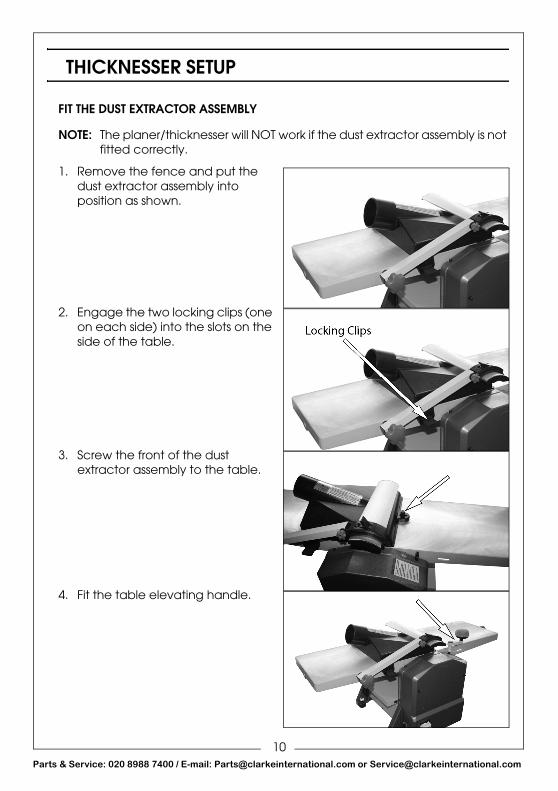
THICKNESSER SETUP
FIT THE DUST EXTRACTOR ASSEMBLY
NOTE: The planer/thicknesser will NOT work if the dust extractor assembly is not fitted correctly.
1. Remove the fence and put the dust extractor assembly into position as shown.
2. Engage the two locking clips (one on each side) into the slots on the side of the table.
3. Screw the front of the dust extractor assembly to the table.
4. Fit the table elevating handle.
10arts & Service: 020 8988 7400 / E-mail: [email protected] or [email protected]

P
OPERATING CONTROLS
POWER
STARTRaise the cover of the ON/OFF switch and press the green ON button, marked ‘I’, and allow the machine to come up to full speed before use.
STOPTo switch OFF, simply press the red button marked ‘O’ and close the cover ensuring it is properly latched.
• If you close the latch at any time the machine will switch off automatically.
RESET SWITCHThe machine is fitted with a thermal overload protector. If the motor stops running or fails to start:
1. Close the safety switch cover and allow the motor to cool for five minutes.
2. Press the reset button.
3. Raise the cover of the ON/OFF switch and press the green ON button, marked ‘I’.
11arts & Service: 020 8988 7400 / E-mail: [email protected] or [email protected]

P
THE PLANER
ADJUSTMENTS
INFEED TABLE HEIGHT ADJUSTMENT
1. Rotate the Infeed Table Height Adjustment knob to set the difference in height between the infeed and outfeed tables.
• This is the amount of material that will be removed with each pass.
• The cutting depth is shown on the scale.
• Best result are obtained using a cutting depth of 0 - 1.5 mm.
CUTTERHEAD GUARD
1. Lift the locking latch, and slide the cutterhead guard away from the fence
2. Place the wood being worked on up against the edge of the cutter.
3. Slide the cutterhead guard as close to the wood as possible (allow room for the wood to slide freely over the cutterhead during use.
WARNING: DISCONNECT THE MACHINE FROM THE POWER SOURCE BEFORE MAKING ANY ADJUSTMENTS. FAILURE TO COMPLY MAY CAUSE SERIOUS INJURY.
12arts & Service: 020 8988 7400 / E-mail: [email protected] or [email protected]

P
FENCE BEVEL ADJUSTMENT
The fence can be tilted backwards up to a maximum of 45o.
1. Loosen the bevel lock handle.
2. Set the fence at the required angle.
• Use the scale (0 - 45o) and pointer shown.
3. Retighten the bevel lock handle.
DUST COLLECTIONBefore operation, connect a suitable dust collector to the dust chute shown.
NOTE: If a dust collection system is not used the quality of your cut will suffer.
USING THE PLANER
DIRECTION OF GRAINIf the wood chips and tears as you cut it, you are probably cutting against the grain. Turn the wood around and feed it in the opposite direction to cut with the grain.
CORRECT OPERATING POSITIONThe operator should stand to one side of the cutterhead.
WARNING: MAKE SURE THAT THE TIMBER IS COMPLETELY FREE OF NAILS, SCREWS AND STAPLES ETC.
13arts & Service: 020 8988 7400 / E-mail: [email protected] or [email protected]

P
HAND PLACEMENTWhen you start,
1. The left hand holds the workpiece down on the infeed table and against the fence while the right hand pushes the workpiece over the cutterhead.
• Use a smooth and even speed.
2. As the workpiece travels over the cutterhead, the new surface rests on the outfeed table, at this point the left hand should be transferred to the outfeed side and presses down on the workpiece on this side.
3. At the same time, maintain forward motion with the right hand. As the right hand approaches the cutter head, Use the push stick supplied to finish the cut.
NOTE: If required, use supports when working with long pieces of wood.
SURFACINGThe purpose of surfacing is to produce one flat surface which can then be milled to the required thickness using the thicknesser.
• Never surface pieces thinner than 75 mm without using a push stick.
• If the board is bowed (curved), place the concave edge down on the infeed table.
• Cut a maximum of 1.5 mm at a time to maintain a good smooth surface reducing to 0.5 - 1 mm for the final cuts.
• Do not try and mill dirty boards, dirt and stones may damage the blades.
• Remove all nails and staples from the wood before you start.
WARNING: NEVER PASS HANDS DIRECTLY OVER THE CUTTERHEAD.
14arts & Service: 020 8988 7400 / E-mail: [email protected] or [email protected]

P
EDGE JOINTINGEdge jointing is the process of creating a finished, flat edge surface that is suitable for joinery or finishing.
It is also a necessary step prior to ripping stock to width on a table saw.
• Always use a push stick when edging a board that is shorter than 300 mm, narrower than 75mm or less than 6mm thick.
• When edging wood wider than 75 mm lap the fingers over the top of the wood, extending them back over the fence such that they will act as a stop for the hands in the event of a kickback.
1. Set the fence to 90°.
• Confirm it with a set square.
2. Inspect stock and grain direction (refer to “Direction of grain” on page 13).
3. If the board is bowed (curved), place the concave edge down on the infeed table.
4. Set the infeed table for a cut of approximately 1 mm.
5. Hold the stock firmly against the fence and table, feed the stock slowly and evenly over the cutterhead.
BEVELINGBeveling an edge is the same operation as edge jointing, except that the fence is tilted to a specified angle.
Several passes may be required to achieve a full bevel.
15arts & Service: 020 8988 7400 / E-mail: [email protected] or [email protected]

P
THE THICKNESSER
BEFORE USE
TABLE HEIGHT ADJUSTMENT
1. Rotate the table elevating handle to raise/lower the table.
• 1 complete turn = 3 mm.
2. The scale shows the estimated height.
NOTE: Use calibrated tools to get exact measurements from the workpiece.
DUST COLLECTIONBefore operation, connect a suitable dust collector to the dust chute shown.
NOTE: If a dust collection system is not used the quality of your cut will suffer.
WARNING: DISCONNECT MACHINE FROM POWER SOURCE BEFORE MAKING ANY ADJUSTMENTS. FAILURE TO COMPLY MAY CAUSE SERIOUS INJURY.
16arts & Service: 020 8988 7400 / E-mail: [email protected] or [email protected]

P
USING THE THICKNESSER
PRECAUTIONS
• Do not try and mill dirty boards, dirt and stones may damage the blades.
• Remove all nails and staples from the wood before thicknessing.
PREPARING THE WORK
1. The thicknesser works best when the wood has at least one flat surface, use the planer to create a flat side.
2. If required, rip the wood in half to reduce warping. You can rejoin the pieces after you have finished milling the wood.
THICKNESSING
1. Start by measuring the thickest part of the board and adjusting the table height on the thicknesser to that dimension.
• Note the grain orientation, and be sure to feed the plank into the machine in the correct direction to avoid tearout.
• Make the first couple of passes with the planned side down on the table.
NOTE: To minimize planer snipe, lift the board slightly as it enters the thicknesser, and again as it comes out.
2. Stay on the infeed side of the machine as you guide the stock through the machine to support the overhanging end.
3. Once the board is half way through the thicknesser and well supported, move to the outfeed side and support the opposite end to keep it from tipping up and into the cutterhead.
4. Raise the table height slightly and repeat until the desired thickness is reached.
WARNING: ALWAYS WEAR ANSI-APPROVED SAFETY GLASSES OR GOGGLES WHEN OPERATING EQUIPMENT
CAUTION: DO NOT THICKNESS A BOARD THAT IS LESS THAN 150 MM LONG. IT IS RECOMMENDED THAT WHEN THICKNESSING SHORT BOARDS YOU BUTT THEM END TO END TO AVOID KICKBACK AND REDUCE SNIPE.
17arts & Service: 020 8988 7400 / E-mail: [email protected] or [email protected]

P
MAINTENANCE
PERIODICALLY• Wipe both the infeed and outfeed rollers with a damp cloth to
remove all traces of contaminants.
• Apply a thin film of wax to the table periodically. This will help keep the table clean and allow the workpiece to slide more easily.
• Inspect the kickback pawls before each operation to ensure they are intact and working properly. They should hang normally and loosely.
• Remove the three dome head nuts, remove the front cover, and lightly oil all pivots, linkages and bearings with good quality machine oil. Ensure the enclosure and all components are perfectly clean before replacing the cover.
WARNING: REMOVE THE PLUG FROM THE MAINS POWER SUPPLY BEFORE CARRYING OUT ANY ADJUSTMENT. SERVICING OR MAINTENANCE
18arts & Service: 020 8988 7400 / E-mail: [email protected] or [email protected]

P
REPLACING CUTTER BLADES
Blades must always be fitted as a pair, and must be of the same type, only fit blades recommended by Clarke International.
1. Turn the cutter height adjuster so that the depth of cut, registered on the scale, is zero.
2. Remove the Angle Fence.
3. Raise the Cutter Guard arm.
4. Turn the cutter block to reveal the five hex. socket head screws securing the cutter blade, then carefully remove them.
5. Remove the cutter support and the blade.
6. Turn the cutter block by 180 degrees and repeat the process.
• ALWAYS replace cutter blades as a pair.
NOTE: Spare blades are available from the Clarke spares department.Part number NXCPT1000110.
7. Replace in reverse order, and, using a straight edge, ensure the cutting edges are level and in line with the table when they are at 12 o’clock.
8. Tighten the securing screws taking care not to over-tighten them.
WARNING: REMOVE THE PLUG FROM THE MAINS POWER SUPPLY BEFORE CARRYING OUT ANY ADJUSTMENT, SERVICING OR MAINTENANCE
WARNING: CUTTERHEAD BLADES ARE DANGEROUSLY SHARP! USE EXTREME CAUTION WHEN INSPECTING, REMOVING, SHARPENING OR REPLACING BLADES INTO THE CUTTERHEAD. FAILURE TO COMPLY MAY CAUSE SERIOUS INJURY!
19arts & Service: 020 8988 7400 / E-mail: [email protected] or [email protected]

P
DRIVE BELT REPLACEMENT
1. Remove the three dome head nuts
2. Remove the front cover.
3. Remove the worn or broken drive belt.
4. Place the replacement drive belt over the small belt wheel.
5. Position part of the drive belt over the large belt wheel.
6. Rotate the large belt wheel by hand in a clockwise direction whilst guiding the belt on to the belt wheel.
NOTE: Spare drive belts are available from the Clarke spares department. -Part number NXCPT1000086.
WARNING: DISCONNECT MACHINE FROM POWER SOURCE BEFORE MAKING ANY ADJUSTMENTS. FAILURE TO COMPLY MAY CAUSE SERIOUS INJURY.
20arts & Service: 020 8988 7400 / E-mail: [email protected] or [email protected]

P
SPECIFICATIONS
Please note that the details and specifications contained herein, are correct at the time of going to print. We reserve the right to change specifications at any time without prior notice.
ENVIRONMENTAL RECYCLING POLICY
Through purchase of this product, the customer is taking on the obligation to deal with the WEEE in accordance with the WEEE regulations in relation to the treatment, recycling & recovery and environmentally sound disposal of the WEEE.
In effect, this means that this product must not be disposed of with general household waste. It must be disposed of according to the laws governing Waste Electrical and Electronic Equipment (WEEE) at a recognised disposal facility.
Model Number CPT1000
Cutterhead Speed 8500 rpm
Dust Port Diameter (Id/od) 68.5/76 mm
Planer
Max Stock Removal 2 mm
Max Cutting Width 254 mm
Fence Size 610 x 125 mm
Fence Angle Range 90°- 135°
Thicknesser
Maximum Width 254 mm
Maximum Cutting Thickness 120 mm
Max Depth Of Cut 2 mm
Feed Rate 6.8 metres/min (average)
Voltage 230V - 50 Hz
Overall Dimensions (Lxwxh) 970 x 520 x 485 mm
Net Weight 27.5 kg
Sound Pressure: Db(A) 91.8 dB
Sound Power Measured Db Lwa 105 dB
21arts & Service: 020 8988 7400 / E-mail: [email protected] or [email protected]

P
DECLARATION OF CONFORMITY
22arts & Service: 020 8988 7400 / E-mail: [email protected] or [email protected]

P
ALSO AVAILABLE FROM YOUR CLARKE DEALER
23arts & Service: 020 8988 7400 / E-mail: [email protected] or [email protected]