Embed Size (px)
Citation preview

ROTOR DYNAMIC BEHAVIOUR OF A HIGH-SPEED OIL-FREE MOTOR COMPRESSOR WITHA RIGID COUPLING SUPPORTED ON FOUR RADIAL MAGNETIC BEARINGS
J. Schmied
Sulzer Escher WyssZurich, Switzerland
J.C. Pradetto
Sulzer Escher WyssZurich, Switzerland
3'7
/,,.._10
SUMMARY
The combination of a high-speed motor, dry gas seals and magnetic bearings realized in this unitfacilitates the elimination of oil. The motor is coupled with a quill shaft to the compressor. This yieldshigher natural frequencies of the rotor than with the use of a diaphragm coupling and helps to maintain asufficient margin of the maximum speed to the frequency of the second compressor bending mode.However, the controller of each bearing then has to take the combined modes of both machines into
account. The requirements for the controller to ensure stability and sufficient damping of all criticalspeeds are described and compared with the implemented controller. The calculated closed loopbehaviour was confirmed experimently, except the stability of some higher modes due to slightfrequency deviations of the rotor model to the actual rotor. The influence of a mechanical damper as adevice to provide additional damping to high modes is demonstrated theoretically. After all, it was notnecessary to install the damper, since all modes could be stabilized by the controller.
INTRODUCTION
The task of the motor compressor unit is to fill a cavern with natural gas for storage purposes. Acompressor without any oil is desirable for this application, since the smallest quantifies of oil in the gascause considerable additional maintenance costs for the pipes. The elimination of any oil could berealized by the combination of a high-speed motor (no gear necessary), dry gas seals replacing oil sealsand magnetic beatings substituting oil bearings. Figure 1 shows a cross section of the compressor andFigure 2 the whole unit. The motor is located in a seperate housing. Its shaft is connected to thecompressor shaft with a quill shaft.
The suction pressure of the compressor is 50 bar and the maximum discharge pressure is 150 bar.
The maximum output of the motor is 2MW and the operating speed ranges from 14000 rpm to 20000rpm.
557
https://ntrs.nasa.gov/search.jsp?R=19940031404 2018-05-26T22:13:59+00:00Z

The discharge pressure of the compressor at the drive end is sealed against atmospheric pressure
with a triple dry gas seal. The helium cooling gas of the motor at the drive end is also sealed with a drygas seal. The thrust bearing and the radial bearing on the non drive end side are surrounded by thenatural gas working fluid, but at a lower pressure than suction pressure in order to reduce windagelosses. This requires another seal between the first compressor stage and the thrust bearing.
Due to the high efficiency requirements, the compressor does not have a balance piston with its
relevant high leakage losses. The thrust is balanced by a digital valve controlling the flow into a chamberat the non drive end of the compressor as a function of the flux of the magnetic thrust bearing, which is
proportional to the thrust force. The resulting pressure in the balance chamber is also sealed with a dry
gas seal.
The main object of the paper is to describe the predicted and measured rotordynamic behaviour ofthis unit and its influence on the design of the digital controller, with special regard to the aspects of the
quill shaft coupling. In comparison with a diaphragm coupling, this type of coupling offers several
advantages:
Less weight (yields higher natural frequencies),additional stiffness (yields higher natural frequencies),
high reliability (the possibility of diaphragm cracks is eliminated),requirement of only one bearing to take the thrust.
The main reason for the choice of the quill shaft is the higher natural frequencies of the rotor yielding a
greater margin of the maximum speed to the second bending mode frequency of the compressor.However, because of this type of coupling the alignment of the compressor had to be handled very
carefully, since it changes the bearing loads, and the controller of each beating had to account for thecombined modes of both rotors (compressor and motor).
DESCRIPTION OF THE ROTOR AND ITS DYNAMIC BEHAVIOUR
The
The basic data of the two shafts connected with a quill shaft are as follows:
Weight of the motor shaft:Weight of the compressor shaft:
Length of the motor shaft:Length of the compressor shaft:Frequency of the first bending mode (motor alone in free condition):Frequency of the first bending mode (compressor alone in free condition):
connecting quill shaft has a length of 285mm and a diameter of 30mm.
240 kg.100 kg.app. 1.1 m.app. 1.2m440 Hz.220 Hz.
Figure 3 shows the modes of the connected shafts at standstill and supported on soft springs. Thevertical lines indicate the sensor (outer lines) and actuator positions (inner lines). It can be seen that each
mode shape exhibits dominating deflections in one of the two rotors; hence they can be classified almostas the modes of the single rotors. However, every mode also has slight deflections in the other rotor.
558

Table 1 shows the observability (sensor not in a node) and commandability (actuator not in a node)of each mode. All modes below the maximum speed (up to the fifth) should be readily observable andcommandable in order to enable the beatings to provide sufficient damping. Higher modes need not bewell damped, but they must not be excited by the bearings. Good observability and commandability ofthese modes are not necessary, and in some cases not desirable either.
Figure 4 shows the natural frequencies of the modes at standstill and at full speed. It shows how thefrequencies are shifted by the gyroscopic effect.The frequencies of the modes above the fourth are notshifted by more than 5%. The magnetic beating controllers must be insensitive to these shifts.
REQUIRED AND REALIZED BEARING TRANSFER FUNCTION
The transfer function of the magnetic bearing (= relation between input (=sensor displacementsignal) and output (= beating force)) is mainly determined by the controller. Hence designing the transferfunction means tuning the controller.
Figures 5,6 and 7 show the realized transfer functions (amplitude and phase) for the motor andcompressor bearings. They also include an approximation for the amplifier and actuator. The motorbearing function has the order 12 in the z domain, those of the two compressor bearings 13. Therelationship between amplitude and phase of the transfer function and stiffness and damping of thebearing is given by the following formulae.
or
A=4(dco) 2 +k 2 (1)
= arctan (d£o/k) (2)
k = A cos ¢ (3)
d = A sin ¢/t.o (4)
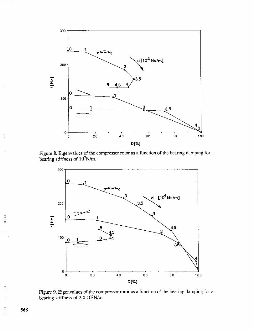
An analysis of the compressor rotor was carded out with two similar bearings having a spring anddamper characteristic in order to get an idea in the design phase of the necessary bearing damping for asufficient damping ratio of all modes below the maximum speed. The noncollocation of sensor andactuator is taken into account as described in/1/and/2/. The analysis was carried out for the compressoronly, because its bending mode is in the operating speed range.
Figures 8 and 9 show the eigenvalues (damping ratio and frequency) of the first three compressor
modes for two beating stiffnesses (107N/m and 2 107N/m) and various bearing damping coefficients.
The stiffness should not be lower than 107N/m in order to enable the bearing to withstand aerodynamic
excitations. On the other hand, it should not be much higher because the bearing damping then becomesless efficient. A damping ratio of 10% is normally the minimum requirement for safe operation in thecritical speed, although much higher damping ratios are possible.
Table 2 shows a comparison of the realized and necessary characteristics needed to damp thecompressor bending mode according to the minimum requirement of 10%. It is not fulfilled on the drive
559

end side, whereas it is surpassed on the non drive side. An analysis of the eigenvalues of the closed loopsystem will show whether the combination can fulfil the requirement.
The modes above the maximum speed, which must not be excited by the bearings, are the reasonthat the realized bearing damping is to be of a magnitude equal to the minimum requirement and notmuch higher. For positive bearing damping, an excitation can happen if the mode shape has a nodebetween sensor and actuator. It can also happen if the bearing damping becomes negative due to phase
losses in the actuator and amplifier or due to phase losses caused by the sampling of the digitalcontroller. In order to prevent an excitation a bad observability or commandability of the mode and a lowamplitude of the transfer function are helpful. A low amplitude in the high frequency region limits thebeating damping at the bending mode frequency. For the well observable and commandable high modes,
the transfer function should provide some damping. This means it should have a phase between either 0 o
and 90 °, or between -180 ° and -270 °. This yields positive damping according to equation (4). The latter
case yields a negative stiffness according to equation (3), but is not destabilizing for high modes. Thecompressor DE bearing can observe and command all modes up to 1500 Hz, most of them well (seetable 1). The tuning of this bearing was particularly difficult therefore. An analysis of the eigenvalueswill show if all modes are stable in the higher frequency region.
THE CLOSED LOOP BEHAVIOUR
Analysis
All analog parts are transformed to the z domain, duly considering the zero order hold, for theanalysis of the closed loop behaviour. The analog parts are the rotor (its finite element model), the sensorand the actuator. These three parts are in series mode at each bearing. The closed loop system with thedigital controller can then be built in the z domain. All these operations are carried out with theprogramme MATLAB. The modeling of the rotor and the plotting of eigenvectors are carried out with thefinite element programme MADYN/3/. Figure 10 provides an overview for the procedure of the closed
loop calculations.
Results
Figure 11 shows the modes (real and imaginary part, which are the shapes at two instances c0t=90 o
apart) of the closed loop system up to 1500 Hz at standstill. The demonstrated modes are only modeswith major deflections in the rotor. They correspond to the modes of the rotor supported on soft springs.Due to the controller coordinates, additional modes arise which are not shown here. They are well
damped, have relative small rotor deflections and normally are of no practical importance.
Table 3 shows the calculated damping ratios as well as a comparison of the calculated frequencies
with measured frequencies. The coincidence of measured and calculated frequencies is not poor up to theseventh mode (second compressor bending mode). There are considerable deviations above this mode.
560

Two of the modes above the maximum speed (20000 rpm = 33 Hz) are unstable: The eighth andeleventh mode. This is due to the inaccurate frequencies of these modes. Due to the deviation of the
calculated frequency, the eighth mode is in a region, where the transfer function of the DE beating of the
compressor has a phase angle of about -150 ° yielding a negative damping. In reality, the frequency is in
a region, where the phase is about -200 ° yielding a positive damping. The other bearings have only verylittle or no influence on the stability of this mode. In case of the eleventh mode, the calculated frequency
is in a region where the motor beating transfer function has a phase angle of about -40 o, hence a negativedamping, whereas in reality the frequency is in a region with positive damping (positive phase angle of
about 45°). The compressor bearings have little or no influence on this mode.
The damping ratios for all modes are sufficently high within the speed range. The first bendingmode of the compressor has the lowest damping ratio of these modes. It is 11.8%, which is still above10%. An unbalance response calculation helps to assess whether this is sufficient to run on the criticalspeed of this mode.
Figure 12 shows the calculated response of all bearing forces to two parallel unbalances of 60gmm at the compressor shaft ends. This corresponds to G2.5. The magnetic bearing capacity fordynamic loads is about 600 N. It is reached at the NDE compressor bearing at the critical speed of thebending mode with a balance quality of G1.8, whereas the achieved balance quality is G0.65. Anunbalance at the shaft ends is very unfavourable (because it is a very sensitive location) and unlikely tooccur in reality. Assuming an unbalance in the middle of the compressor yields even more margin. Thepermissible unbalance then is more than twice as high. This proved to be sufficient during the extensivetest programme of the machine.
EFFECT OF A MECHANICAL DAMPER
Figure 13 shows a sketch of a mechanical damper, which can be mounted on the non drive end sideof the compressor. Its purpose is to provide additional damping to the higher modes above the maximumspeed. It was prepared as a way out in case the tuning of the magnetic bearing proved unsuccessful. Itwas not necessary to be installed after all. However, its effect was studied theoretically. For thispurpose, the damper was modeled as a concentrated mass (without moments of inertia) attached to therotor with a spring and damper. The data are as follows:
Mass:
Stiffness:
Damping ratio (damper alone):
m-- 1.5kg
k = 2.1 107 N/m --> fk = (4k/m)/(2n) = 600 Hz
D= 25%, 50%
Since they were not exactly known two values were assumed for the damping ratio.
Figure 14 shows the effect of the damper on the frequencies and damping ratios of all modes up to1500 Hz. The high compressor modes 5 to 8 and 10 are affected more than the motor modes 9 and 11.The damping effect on the compressor modes above the damper mode is considerable. The frequenciesabove the damper mode are increased for a damper damping ratio of 25%, whereas they are slightlydecreased as all the others for the 50% case.
561

CONCLUSIONS
A transfer function of the magnetic bearings was designed which is able to fulfil all necessaryrequirements: It provides sufficient damping to all modes below maximum speed, especially to thecompressor bending mode, which is in the operating speed range and is able to ensure the stability of allmodes above maximum speed. This was achieved in spite of a rigid coupling with the consequence, thateach bearing has to consider the modes of both rotors. The main advantage of the coupling is a highermargin of the maximum speed to the frequency of the second compressor bending mode. It was notnecessary to mount a mechanical damper, which could provide additional damping to the higher modes,as was shown theoretically.
ACKNOWLEDGEMENTS
The authors wish to thank all partners concerned with this project for their excellent cooperation:The magnetic bearing manufacturer S2M in France, the motor manufacturer ACEC in Belgium, themanufacturer of the frequency inverter for the motor, HILL GRAHAMS CONTROL, in England and theseal manufacturer, JOHN CRANE, in England.
REFERENCES
.
Q
,
Schmied, J.: Experience with Magnetic Bearings Supporting a Pipeline Compressor. Proceedingsof the 2nd International Symposium on Magnetic Bearing, July 12-14, 1990, Tokyo, Japan.
Schmied, J., Pradetto, J.C.: Selbsterregte Schwingungen bei magnetgelagerten Rotoren. VDIBerichte Nr. 957, 1992.
Klement, H.D.: MADYN - Ein Programmsystem ffir die Maschinenberechnung. Unix/mail 5
(1987).
562

Table1.ObservabilivandCommandabilit,/ofNaturalModesmode motorNDE motorDE comp.DE1,motorparallel O'_es / C yes O :¢es / C yes O weak / C weak
comp. parallel O yes / C yes O yes / C yes O yes / C yes2._
3, motor tilting O yes / C yes
4, comp. tilting O yes / C yes
5, 1.bend. comp. O weak / C weak
6, 2.bend. comp. O weak / C weak* O weak / C weak7, 2.bend. comp.
8, 3.bend. comp. O weak/C weak
9, 1.bend. motor O yes / C yes
10, 3.bend.comp. + O yes / C yes
11, 2.bend.motor O yes / C yes O yes / C no
* Quill shaft has one more node compared to 6.+ Quill shaft has one more node compared to 8.
O = ObservabilityC = Commandability
0 ],'es / C _¢es0 yes / C yesO weak / C weak
O weak / C weak
O weak / C weak
O weak / C no
'C _,es/O yesO yes / C yes
0 yes / C yes
0 yes / C yes0 yes / C yes
0 yes / C yes0 yes / C yes
O yes / C yesO yes / C yesO yes / C yes
O weak / C weak
comp. NDEO no/C no
0 yes / C yes0 yes / C yes
0 yes / C yes0 yes / C yes
0 yes / C yes0 yes / C no
O no / C yesO no / C yeso yes / c yes
o weak / c weak
Table 2. Necessar
k [N/m]
d [Ns/m]
A [N/m]
[degree]
and Realized Corn
according to
figure 5107
8000
1.55 107
5O
)ressor Bearin$ Characteristics at the Bending Mode Frecaccording to DE bearing NDE bearing
figure 62 107 1.66 107 2.3 107
8000 2.44 103 1.4 104
2.4 107 1.7 107 3.2 107
33 12.5 42
uency.
Table 3. Frequencies and Damping Ratios of the Closed Loop Systemmode fcalculated [Hz] Dcalculated [%] foaeasured[Hz]
1, motor parallel
2, comp.parallel
3, motor tiltin_
4, comp. tilting
5, 1.bend. comp.6, 2.bend.comp.
7, 2.bend.comp.*8, 3.bend.comp.
9, 1.bend.motor
10, 3.bend.comp. +11, 2.bend.motor
45.568.1102.1
124.7
243.2
389.5
514.8
754.7
1038.7
1158.4
1470.9
31.3
23.2
27.534.1
11.6
1.9
0.1
- 1.8(unstable)0.5
0.2
- 1.0(unstable)
* Quill shaft has one more node compared to 6.+ Quill shaft has one more node compared to 8.
45
68102
125
240
405
540
840
1180
1350
IAf/fmeasuredl0.0 %
0.0 %0.0 %
0.2 %
1.3 %
3.8 %
4.7 %
10.1%
1.8 %
9.0 %
563
1 Auxiliary bearings
2 Radial magnetic bearings3 Axial magnetic bearing
Figure 1. Cross section of the compressor.
_ 23
i
• _ _+_..._I-- _._+._ ""
_,-_-L___--N__k_,
NDE
_ Motor
_'_- ,,'r,, "L,\ pressor
I- ;2
Figure 2. Arrangement of the motor compressor unit.
564

Mode Shape Number, Frequency
1, 15.0Hz
2, 22.4Hz
3, 29.2Hz
4, 76.4Hz
5, 220.9I lz
6, 378.9Hz
7, 515.4Hz
8, 787.1Hz
9, 994.9Hz
10, 1162.5Hz
I 1, 1463.0Hz
Figure 3. Modes of the coupled shaft supported on soft springs (k= 106N/m).
565

W"I-
10000
1000
100
[] n=2OOOOrpmbackward whirling
[] n:O
[] n=2OOOOrpmforward whirling
?
10
1 2 3 4 5 6 7 8 9 10 11
Mode Number
Figure 4. Natural frequencies of the shaft at standstill and fu]] speed.
E
z
:3
-&E<
xlO 83
I •
0 I I I j
200 400 600 1800800 1000 1200 1400 1600
Frequency [Hz]
2000
10
0
_. -200
f .....
i
2OOi i i i i J I I
400 600 800 1000 1200 1400 1600 1800
Frequency [Hz]
Figure 5. Transfer function ofthemotormagneticbearings.
2O00
566

E
z
"03
°_
O.
E,<
xlO 8, ,
200 400 600 800 i000 1200 1400 1600 1800 2000
Frequency [Hz]
0
0
_. -200
i
200
i400 600 800 1000 1200 1400 1600 1800
Frequency [Hz]
Figure 6. Transfer function of the DE compressor magnetic beating.
2OOO
E
Z
"10
-.-_.
O.
xlO ei , , i J
200 400 600 800 1000 1200 1400 1600 1800 2000
Frequency [Hz]
0
(/10
__ -200
i
t I I i i i i i u
200 400 600 800 1000 1200 1400 1600 1800 2000
Frequency [Hz]
Figure 7. Transfer function of the NDE compressor magnetic bearing.
567
-r
,#,.
300
200
100
o i
_10 4 Ns/m]_
s 4_s _4./3.s
o !
! t
0 20 40
3.5
60 80 100
D[%]
Figure 8. Eigenvalues of the compressor rotor as a function of the bearing damping for a
bearing stiffness of 107N/m.
300
2OO
0
lOO 1 3
_d rlO4Ns/m]
3.5 "_
4
568
i ! J |
0 20 40 60 80 100
D[%]
Figure 9. Eigenvalues of the compressor rotor as a function of the bearing damping for a
bearing stiffness of 2.0 107N/m.

• MADYN •
Creating the FE Modelof the Rotor
=>
Mass martix MStiffness matrix KGyroscopic matdx G
Plotting the Eigenvalue
MATLAB
Creating the System Matrixof the Rotor
=> A Rotor
Creating the System Matrixof the Closed Loop System
=> A Total
Creating theController Matrices
----.>
ql_ A ControllerB ControllerC ControllerD Controller
I_'0_nv_'u,_x'r_c"onII"_s_on.oC_'cu'_"ooI
i
Figure 10. Procedure for closed loop calculations.
569

Im
Re
Im
Re
Im
Re
Im
Re
Im
Re
Im
Re
Im
Re
Im
Re
Im
Re
Im
Re
Im
Re
Mode Shape
"l-t ....... tt'_ ' _-_'*'-'11-'"
"-l"t ....... 1-1+" =_tl"-'
...... -L.-_-4i _" +- 1T"-"
""/T--"- ...... ii _ _ _i ....
tr li + + = ii ....... " ....
-|1
"l't +,i-- + _ - = ii ......... ii + -
Number, Freq., Damp.Ratio
1, 45.5tlz, 31.3%
2, 68.1t-tz, 23.2%
3, 102.1Hz, 27.5%
4, 124.7Hz, 34.1%
5, 243.2Hz, 11.6%
6, 389.5Hz, 1.9%
7, 514.8Hz, 0.1%
8, 754.7Hz, - 1.8%
9, 1038.7Hz, 0.5%
10, 1158.4Hz, 0.2%
11, 1470.9Hz, -1.0%
Figure 11. Rotor modes of the closed loop system.
- 570

Z
o)I.)
1000
L
0,, 500
E
O
0
i i
--.--Comp. NDE Beoring... Comp. DE Beoring
! ! i i
----Motor DE Beoring"--=-=-Motor: NDE Beoring ..............................
• , , , ,
i--i , , i i I , ,_' II
50 1O0 150
I I I I
200 250 300 350
Frequency [Hz]
Figure 12. Bearing responses to a parallel unbalance (G2.5) in the compressor.
Shaft End
i i Damper Mass
I •
Rings providingStiffness and Damping
Figure 13. Sketch of the mechanical damper.
571

N-I-
r-tJ
Or-
i._.
I,,I.
2O
10
[] D Damper 25%
[] D Damper50%
location of damper mode
5 6 7 8 9 10 11
Mode Number
o_
Oli
t"ieQ.
E
e
CO
if
iw
"ID"ID
6
• D Damper 25%
[] D Damper 50%
location of damper mode
5 6 7 8 9 10
Mode Number
Figure 14. Effect of a mechanical damper on the rotor modes.
11
572

,,-lm.-'--
._j_! I
Session lOa - Controls
Chairman: Alexander V. Kuzin
Moscow Aviation Technological Institute
573