Embed Size (px)
Citation preview

10 Mb/s visible light transmission system usinga polymer light-emitting diode
with orthogonal frequency division multiplexingSon T. Le,1,* T. Kanesan,2,9 F. Bausi,6,7,11 P. A. Haigh,3,4,10 S. Rajbhandari,5 Z. Ghassemlooy,3 I. Papakonstantinou,4,7
W. O. Popoola,8 A. Burton,3 H. Le Minh,3 F. Cacialli,6,7 and A. D. Ellis11Aston Institute of Photonic Technologies, Aston University, Birmingham B4 7ET, UK
2Telekom Research & Development (TM R&D), TM Innovation Centre, 63000 Cyberjaya, Selangor, Malaysia3Optical Communications Research Group, Northumbria University, Newcastle-upon-Tyne, NE1 8ST, UK
4Department of Electronic and Electrical Engineering, University College London, WC1E 6BT, UK5Department of Engineering Science, University of Oxford, Parks Road, Oxford OX1 3PJ, UK
6Department of Physics and Astronomy, University College London, WC1E 6BT, UK7London Centre for Nanotechnology, University College London, WC1E 6BT, UK
8School of Engineering and Built Environment, Glasgow Caledonian University, Glasgow G4 0BA, UK9e-mail: [email protected]
10e-mail: [email protected]: [email protected]
*Corresponding author: [email protected]
Received April 16, 2014; revised May 27, 2014; accepted May 27, 2014;posted May 28, 2014 (Doc. ID 210276); published June 24, 2014
We present a newly designed polymer light-emitting diode with a bandwidth of ∼350 kHz for high-speedvisible light communications. Using this new polymer light-emitting diode as a transmitter, we have achieved arecord transmission speed of 10 Mb∕s for a polymer light-emitting diode-based optical communication system withan orthogonal frequency division multiplexing technique, matching the performance of single carrier formats usingmultitap equalization. For achieving such a high data-rate, a power pre-emphasis technique was adopted. © 2014Optical Society of AmericaOCIS codes: (060.4510) Optical communications; (250.3680) Light-emitting polymers.http://dx.doi.org/10.1364/OL.39.003876
With the exponentially increasing demand for datacaused by the limited (and therefore expensive) radiofrequency bandwidth available, researchers are increas-ingly turning to optical domain technologies such asvisible light communications (VLC). The optical transmit-ters in VLC links are generally accepted as phosphor-converted gallium nitride (GaN) light-emitting diodes(LEDs) due to their high optical power and simplicityof implementation. Thus the vast majority of experimen-tal research reported in the field has utilized just a soli-tary LED to achieve high throughputs [1–3]. GaN LEDsare produced using epitaxial methods that result in brittlecrystals; as such it is not trivial to produce devices withlarge photoactive areas. To provide illumination in ahome/office environment would therefore require a ma-trix of LEDs, which has its own associated problemssuch as resonance in the circuitry and increasing systemcomplexity. A simpler approach would be to use a singlepanel with a large photoactive area.As an alternative to inorganic LEDs, we consider here
organic, polymeric LEDs (PLEDs) as the transmitter.Organic electronics is a technology that allowssolution-based fabrication of semiconductor devices toconcurrently have the properties of plastics (i.e.,mechanical flexibility and arbitrary shape) and the con-duction properties of metals as well as bandgap tuning byselection of polymer to control the emission wavelength.These advantages are very important for VLC systems,especially considering that large panel illumination
devices can be produced with unrestricted shapes andsizes. As VLC becomes more prevalent in modern tech-nologies, as is reflected in the increasing number ofVLC start-up companies, we predict that new PLED-based screens, monitors, and devices will begin to arrivepackaged with VLC capability. Therefore it is imperativeto investigate the suitability of a range of PLED-basedVLC systems across a wide gamut of modulation formatsand signal-processing techniques.
However, the major challenge when adopting PLEDsfor VLC systems is the relatively small raw bandwidth.The polymers used as semiconductors in PLEDs arecharacterized by the charge transport mobilities that areorders of magnitude lower than those available in crys-talline inorganic semiconductors. In turn this causes a re-stricted PLED bandwidth that is also orders of magnitudelower than that obtainable from inorganic LEDs. As a re-sult, achieving high-capacity data communications withPLEDs is a substantial challenge that needs addressing.
Several reports of high throughput polymer VLC(PVLC) links are available in the literature. In [4] a9.3 Mb∕s link is experimentally demonstrated using theon–off-keying (OOK) modulation format and a 270 kHzbandwidth PLED in real time with an FPGA. This trans-mission data rate was achieved using a least meansquares equalizer with 25 tapped weight coefficients. In[5] a transmission speed of 2.7 Mb∕s was reported for asystem that only utilized ∼90 kHz bandwidth with an ar-tificial neural network equalizer. However, these digital
3876 OPTICS LETTERS / Vol. 39, No. 13 / July 1, 2014
0146-9592/14/133876-04$15.00/0 © 2014 Optical Society of America
signal processing (DSP) based equalization techniquesare highly computationally complex. Therefore, in orderto bring PVLC systems closer to real-world applications,more DSP-efficient modulation formats and transmissionschemes should be considered and explored.It has been demonstrated that discrete multitone
modulation schemes such as orthogonal frequencydivision multiplexing (OFDM) considerably outperformunequalized time-domain modulation schemes such asOOK in VLC systems due to their high spectral efficiency,meaning that multiple bits per symbol can be transmittedto achieve a much higher bit rate [6]. In addition, OFDMis extremely robust against frequency-selective and mul-tipath fading channels, resulting in inherent protectionagainst intersymbol interference (ISI), thus makingOFDM the dominant modulation format in current RFwireless communications. As a result, OFDM has beenconsidered a strong candidate for future VLC applica-tions due to its inherent resilience to ISI [3,7]. However,there is a lack of reported research on the performanceof OFDM in PVLC-based systems. To the best of ourknowledge, the only demonstration of an organic VLClink with OFDM was reported in [8], at a bit rate of1.4 Mb∕s using a bandwidth of 93 kHz.In this Letter, we present a 10 Mb∕s PVLC link using
custom-designed PLEDs with an increased device band-width of ∼350 kHz, which is a noteworthy improvementof around four times over [8]. The increase in bandwidthis achieved by using thermal annealing above the glasstransition temperature of the polymer during the PLEDmanufacturing process. This results in a lower turn-onvoltage and higher currents for a certain voltage, com-pared with that in our previous reports. Thermalannealing is expected to facilitate packing of the differentpolymer chains and therefore favor higher charge mobil-ities. By using such a PLED with OFDM as the transmis-sion scheme and a power pre-emphasis technique toincrease the bandwidth efficiency, we have successfullytransmitted a 10 Mb∕s data stream without the use of anycomplex multitap equalization schemes. In comparisonwith the previous PVLC OFDM transmission systems[8], this represents significant improvements both inthe achievable data rate (10 Mb∕s in comparison to1.4 Mb∕s) and also in the net data-rate/bandwidth gain(30 times here in comparison to 14 times in [8]). Forthe purpose of comparison, we also present here theperformance of an unequalized OOK system using thesame PLED.One of the main limits of organic-based photonic devi-
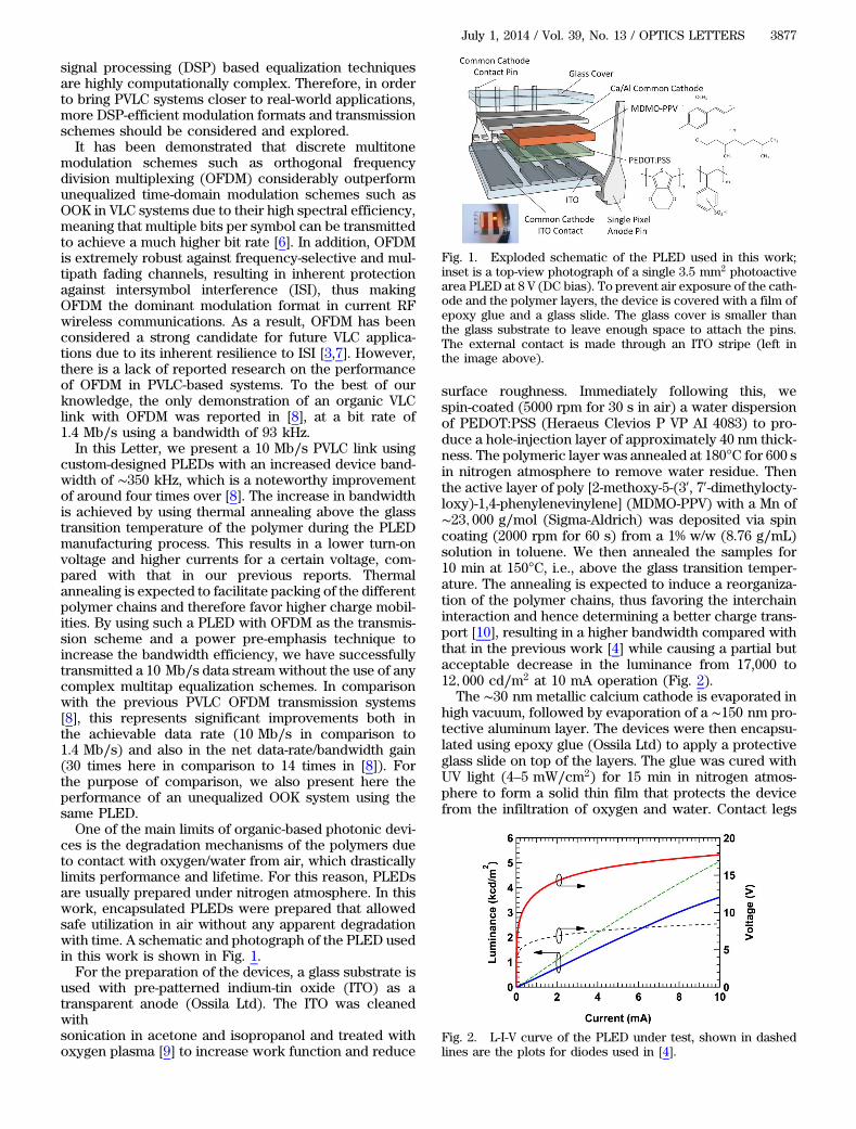
ces is the degradation mechanisms of the polymers dueto contact with oxygen/water from air, which drasticallylimits performance and lifetime. For this reason, PLEDsare usually prepared under nitrogen atmosphere. In thiswork, encapsulated PLEDs were prepared that allowedsafe utilization in air without any apparent degradationwith time. A schematic and photograph of the PLED usedin this work is shown in Fig. 1.For the preparation of the devices, a glass substrate is
used with pre-patterned indium-tin oxide (ITO) as atransparent anode (Ossila Ltd). The ITO was cleanedwithsonication in acetone and isopropanol and treated withoxygen plasma [9] to increase work function and reduce
surface roughness. Immediately following this, wespin-coated (5000 rpm for 30 s in air) a water dispersionof PEDOT:PSS (Heraeus Clevios P VP AI 4083) to pro-duce a hole-injection layer of approximately 40 nm thick-ness. The polymeric layer was annealed at 180°C for 600 sin nitrogen atmosphere to remove water residue. Thenthe active layer of poly [2-methoxy-5-(30, 70-dimethylocty-loxy)-1,4-phenylenevinylene] (MDMO-PPV) with a Mn of∼23; 000 g∕mol (Sigma-Aldrich) was deposited via spincoating (2000 rpm for 60 s) from a 1% w/w (8.76 g∕mL)solution in toluene. We then annealed the samples for10 min at 150°C, i.e., above the glass transition temper-ature. The annealing is expected to induce a reorganiza-tion of the polymer chains, thus favoring the interchaininteraction and hence determining a better charge trans-port [10], resulting in a higher bandwidth compared withthat in the previous work [4] while causing a partial butacceptable decrease in the luminance from 17,000 to12; 000 cd∕m2 at 10 mA operation (Fig. 2).
The ∼30 nm metallic calcium cathode is evaporated inhigh vacuum, followed by evaporation of a ∼150 nm pro-tective aluminum layer. The devices were then encapsu-lated using epoxy glue (Ossila Ltd) to apply a protectiveglass slide on top of the layers. The glue was cured withUV light (4–5 mW∕cm2) for 15 min in nitrogen atmos-phere to form a solid thin film that protects the devicefrom the infiltration of oxygen and water. Contact legs
Fig. 1. Exploded schematic of the PLED used in this work;inset is a top-view photograph of a single 3.5 mm2 photoactivearea PLED at 8 V (DC bias). To prevent air exposure of the cath-ode and the polymer layers, the device is covered with a film ofepoxy glue and a glass slide. The glass cover is smaller thanthe glass substrate to leave enough space to attach the pins.The external contact is made through an ITO stripe (left inthe image above).
Fig. 2. L-I-V curve of the PLED under test, shown in dashedlines are the plots for diodes used in [4].
July 1, 2014 / Vol. 39, No. 13 / OPTICS LETTERS 3877
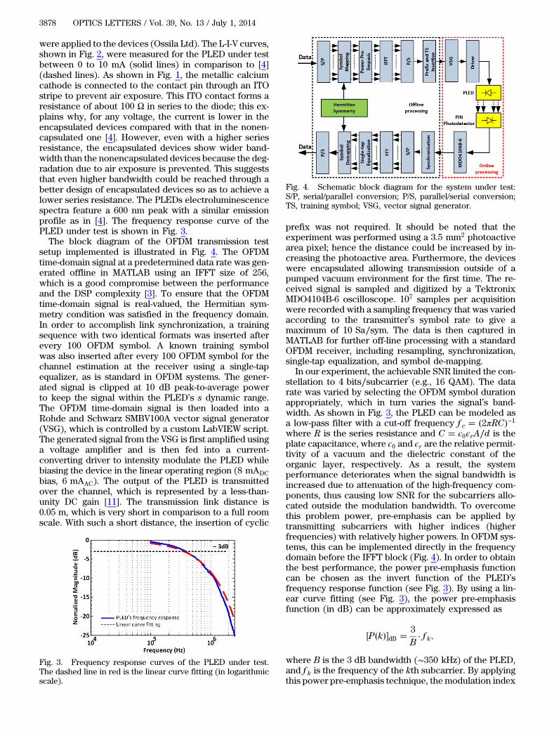
were applied to the devices (Ossila Ltd). The L-I-V curves,shown in Fig. 2, were measured for the PLED under testbetween 0 to 10 mA (solid lines) in comparison to [4](dashed lines). As shown in Fig. 1, the metallic calciumcathode is connected to the contact pin through an ITOstripe to prevent air exposure. This ITO contact forms aresistance of about 100 Ω in series to the diode; this ex-plains why, for any voltage, the current is lower in theencapsulated devices compared with that in the nonen-capsulated one [4]. However, even with a higher seriesresistance, the encapsulated devices show wider band-width than the nonencapsulated devices because the deg-radation due to air exposure is prevented. This suggeststhat even higher bandwidth could be reached through abetter design of encapsulated devices so as to achieve alower series resistance. The PLEDs electroluminescencespectra feature a 600 nm peak with a similar emissionprofile as in [4]. The frequency response curve of thePLED under test is shown in Fig. 3.The block diagram of the OFDM transmission test
setup implemented is illustrated in Fig. 4. The OFDMtime-domain signal at a predetermined data rate was gen-erated offline in MATLAB using an IFFT size of 256,which is a good compromise between the performanceand the DSP complexity [3]. To ensure that the OFDMtime-domain signal is real-valued, the Hermitian sym-metry condition was satisfied in the frequency domain.In order to accomplish link synchronization, a trainingsequence with two identical formats was inserted afterevery 100 OFDM symbol. A known training symbolwas also inserted after every 100 OFDM symbol for thechannel estimation at the receiver using a single-tapequalizer, as is standard in OFDM systems. The gener-ated signal is clipped at 10 dB peak-to-average powerto keep the signal within the PLED’s s dynamic range.The OFDM time-domain signal is then loaded into aRohde and Schwarz SMBV100A vector signal generator(VSG), which is controlled by a custom LabVIEW script.The generated signal from the VSG is first amplified usinga voltage amplifier and is then fed into a current-converting driver to intensity modulate the PLED whilebiasing the device in the linear operating region (8 mADCbias, 6 mAAC). The output of the PLED is transmittedover the channel, which is represented by a less-than-unity DC gain [11]. The transmission link distance is0.05 m, which is very short in comparison to a full roomscale. With such a short distance, the insertion of cyclic
prefix was not required. It should be noted that theexperiment was performed using a 3.5 mm2 photoactivearea pixel; hence the distance could be increased by in-creasing the photoactive area. Furthermore, the deviceswere encapsulated allowing transmission outside of apumped vacuum environment for the first time. The re-ceived signal is sampled and digitized by a TektronixMDO4104B-6 oscilloscope. 107 samples per acquisitionwere recorded with a sampling frequency that was variedaccording to the transmitter’s symbol rate to give amaximum of 10 Sa∕sym. The data is then captured inMATLAB for further off-line processing with a standardOFDM receiver, including resampling, synchronization,single-tap equalization, and symbol de-mapping.
In our experiment, the achievable SNR limited the con-stellation to 4 bits∕subcarrier (e.g., 16 QAM). The datarate was varied by selecting the OFDM symbol durationappropriately, which in turn varies the signal’s band-width. As shown in Fig. 3, the PLED can be modeled asa low-pass filter with a cut-off frequency f c � �2πRC�−1where R is the series resistance and C � ϵ0ϵrA∕d is theplate capacitance, where ϵ0 and ϵr are the relative permit-tivity of a vacuum and the dielectric constant of theorganic layer, respectively. As a result, the systemperformance deteriorates when the signal bandwidth isincreased due to attenuation of the high-frequency com-ponents, thus causing low SNR for the subcarriers allo-cated outside the modulation bandwidth. To overcomethis problem power, pre-emphasis can be applied bytransmitting subcarriers with higher indices (higherfrequencies) with relatively higher powers. In OFDM sys-tems, this can be implemented directly in the frequencydomain before the IFFT block (Fig. 4). In order to obtainthe best performance, the power pre-emphasis functioncan be chosen as the invert function of the PLED’sfrequency response function (see Fig. 3). By using a lin-ear curve fitting (see Fig. 3), the power pre-emphasisfunction (in dB) can be approximately expressed as
�P�k��dB � 3B· f k;
where B is the 3 dB bandwidth (∼350 kHz) of the PLED,and f k is the frequency of the kth subcarrier. By applyingthis power pre-emphasis technique, the modulation index
Fig. 3. Frequency response curves of the PLED under test.The dashed line in red is the linear curve fitting (in logarithmicscale).
Fig. 4. Schematic block diagram for the system under test:S/P, serial/parallel conversion; P/S, parallel/serial conversion;TS, training symbol; VSG, vector signal generator.
3878 OPTICS LETTERS / Vol. 39, No. 13 / July 1, 2014
of the transmitter will be nearly independent of thefrequency (Fig. 5), thus allowing the transmission of asignal with a much larger bandwidth in comparison tothe PLEDs bandwidth, meaning a relatively high netdata-rate/bandwidth gain.The received constellation diagrams at 4.5 Mb∕s with-
out power pre-emphasis before and after single-tapequalization are shown in Figs. 6(a) and 6(b), respec-tively. A 16 QAM modulation format was adopted. It isclear that the PLED and the system front end not onlyintroduce amplitude distortion (acting as a low-pass fil-ter) but also phase distortion (introducing a frequency-dependent positive phase shift). As a result, with the in-crease of subcarrier index (frequency), these amplitudeand phase distortion perturbations rescale and rotate thereceived constellation points simultaneously. However,both the amplitude and phase distortions introducedby the PLED are frequency-dependent and thus can beeffectively corrected by transmitting a known symboland performing single-tap equalization with the zero-forcing method. At a bit rate of 4.5 Mb∕s, the data canbe recovered with a bit error rate (BER) of ∼5.6 × 10⁻³.The BER performance of the investigated OFDM sys-
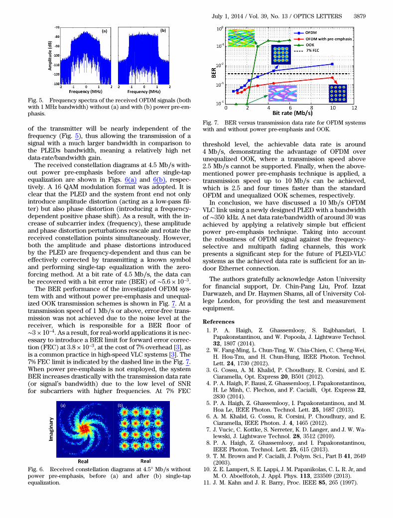
tem with and without power pre-emphasis and unequal-ized OOK transmission schemes is shown in Fig. 7. At atransmission speed of 1 Mb∕s or above, error-free trans-mission was not achieved due to the noise level at thereceiver, which is responsible for a BER floor of∼3 × 10⁻⁴. As a result, for real-world applications it is nec-essary to introduce a BER limit for forward error correc-tion (FEC) at 3.8 × 10⁻³, at the cost of 7% overhead [3], asis a common practice in high-speed VLC systems [3]. The7% FEC limit is indicated by the dashed line in the Fig. 7.When power pre-emphasis is not employed, the systemBER increases drastically with the transmission data rate(or signal’s bandwidth) due to the low level of SNRfor subcarriers with higher frequencies. At 7% FEC
threshold level, the achievable data rate is around4 Mb∕s, demonstrating the advantage of OFDM overunequalized OOK, where a transmission speed above2.5 Mb∕s cannot be supported. Finally, when the above-mentioned power pre-emphasis technique is applied, atransmission speed up to 10 Mb∕s can be achieved,which is 2.5 and four times faster than the standardOFDM and unequalized OOK schemes, respectively.
In conclusion, we have discussed a 10 Mb∕s OFDMVLC link using a newly designed PLED with a bandwidthof ∼350 kHz. A net data rate/bandwidth of around 30 wasachieved by applying a relatively simple but efficientpower pre-emphasis technique. Taking into accountthe robustness of OFDM signal against the frequency-selective and multipath fading channels, this workpresents a significant step for the future of PLED-VLCsystems as the achieved data rate is sufficient for an in-door Ethernet connection.
The authors gratefully acknowledge Aston Universityfor financial support, Dr. Chin-Pang Liu, Prof. IzzatDarwazeh, and Dr. Haymen Shams, all of University Col-lege London, for providing the test and measurementequipment.
References
1. P. A. Haigh, Z. Ghassemlooy, S. Rajbhandari, I.Papakonstantinou, and W. Popoola, J. Lightwave Technol.32, 1807 (2014).
2. W. Fang-Ming, L. Chun-Ting, W. Chia-Chien, C. Cheng-Wei,H. Hou-Tzu, and H. Chun-Hung, IEEE Photon. Technol.Lett. 24, 1730 (2012).
3. G. Cossu, A. M. Khalid, P. Choudhury, R. Corsini, and E.Ciaramella, Opt. Express 20, B501 (2012).
4. P. A. Haigh, F. Bausi, Z. Ghassemlooy, I. Papakonstantinou,H. Le Minh, C. Flechon, and F. Cacialli, Opt. Express 22,2830 (2014).
5. P. A. Haigh, Z. Ghassemlooy, I. Papakonstantinou, and M.Hoa Le, IEEE Photon. Technol. Lett. 25, 1687 (2013).
6. A. M. Khalid, G. Cossu, R. Corsini, P. Choudhury, and E.Ciaramella, IEEE Photon. J. 4, 1465 (2012).
7. J. Vucic, C. Kottke, S. Nerreter, K. D. Langer, and J. W. Wa-lewski, J. Lightwave Technol. 28, 3512 (2010).
8. P. A. Haigh, Z. Ghassemlooy, and I. Papakonstantinou,IEEE Photon. Technol. Lett. 25, 615 (2013).
9. T. M. Brown and F. Cacialli, J. Polym. Sci., Part B 41, 2649(2003).
10. Z. E. Lampert, S. E. Lappi, J. M. Papanikolas, C. L. R. Jr, andM. O. Aboelfotoh, J. Appl. Phys. 113, 233509 (2013).
11. J. M. Kahn and J. R. Barry, Proc. IEEE 85, 265 (1997).
Fig. 5. Frequency spectra of the received OFDM signals (bothwith 1 MHz bandwidth) without (a) and with (b) power pre-em-phasis.
Fig. 6. Received constellation diagrams at 4.5° Mb∕s withoutpower pre-emphasis, before (a) and after (b) single-tapequalization.
Fig. 7. BER versus transmission data rate for OFDM systemswith and without power pre-emphasis and OOK.
July 1, 2014 / Vol. 39, No. 13 / OPTICS LETTERS 3879