Embed Size (px)
Citation preview

H26-260L
Spanish TitleTranslation
French TitleTranslation
Instruction ManualManuel d’utilisationManual de instrucciones
Français (16) Español (30)
www.DeltaMachinery.com
To reduce risk of serious injury, thoroughly read and comply with all warnings and instructions inthis manual and on product.KEEP THIS MANUAL NEAR YOUR SAW FOR EASY REFERENCE AND TO INSTRUCT OTHERS
10-INCH COMPOUND MITER SAW
1 2 3 4 5 6 7

TABLE OF CONTENTSIMPORTANT SAFETY INSTRUCTIONS ................................... 2
safety logos ......................................................................... 3GENERAL POWER TOOL SAFETY RULES ............................ 3MITER SAW SAFETY RULES ................................................... 4POWER CONNECTIONS .......................................................... 5
Double Insulation ................................................................. 5Electrical Connection .......................................................... 6Extension Cords .................................................................. 6
FEATURES ................................................................................ 6Product Specifications ........................................................ 6Know Your Compound Miter Saw ...................................... 7
UNPACKING AND ASSEMBLY ................................................ 8ASSEMBLY ................................................................................. 9
Mounting the Saw to a Stable Surface ............................. 10Attach Horizontal Work Clamp .......................................... 10Install Dust Collection Bag ................................................ 11Install Batteries for Laser ................................................... 11
PREPARING YOUR SAW FOR USE ....................................... 12Install/Replace the Blade .................................................. 12Square the Blade to the Fence ......................................... 13Align the Blade to the Table .............................................. 14Align the Laser Guide ........................................................ 15 To Remove Your Mark ............................................... 15 To Cut on Your Mark .................................................. 15 To Cut without Removing Your Mark ......................... 15
OPERATION ............................................................................. 16Applications ....................................................................... 16Cross Cuts ......................................................................... 17Bevel Cuts ......................................................................... 17Compound Miter Cuts ....................................................... 17
TIPS FOR CUTTING AND SUPPORTING WORKPIECES .... 18Tips for Cutting Crown Molding ........................................ 18 Cutting Warped Material ................................................... 19Clamping Wide Workpieces .............................................. 19Supporting Long Workpieces............................................ 20
ADJUSTMENTS ....................................................................... 20Arm Pivot ........................................................................... 20Positive Stop Screw .......................................................... 20Bevel Pivot ........................................................................ 21Depth Stop ........................................................................ 21Laser Guide ....................................................................... 21
MAINTENANCE ...................................................................... 22Keep Machine Clean ......................................................... 22General Maintenance ........................................................ 22Lubrication ......................................................................... 22Brush Replacement ........................................................... 22
TROUBLESHOOTING ............................................................. 23Failure to Start ................................................................... 23
ACCESSORIES ........................................................................ 23PARTS, SERVICES AND WARRANTY ASSISTANCE ........... 23THREE-YEAR LIMITED WARRANTY .................................... 23REPLACEMENT PARTS .......................................................... 24SERVICE AND REPAIRS ......................................................... 24
IMPORTANT SAFETY INSTRUCTIONS CAREFULLY READ AND FOLLOW ALL WARNINGS AND INSTRUCTIONS ON YOUR
PRODUCT AND IN THIS MANUAL. SAVE THIS MANUAL. MAKE SURE ALL USERS ARE FAMILIAR WITH ITS WARNING AND INSTRUCTIONS WHEN USING THE TOOL. Improper operation, maintenance or modification of tools or equipment could result in serious injury and/or property damage.If you have any questions or concerns relative to the use of your tool or the contents of this manual, stop using the tool and contact DELTA® Power Equipment Corporation Customer Care at 1-800-223-7278.
SAFETY LOGOSThe definitions below describe the level of severity for each signal word. Please read the manual and pay attention to these symbols.
Indicates an imminently hazardous situation which, if not avoided, will result in death or serious injury.Indicates a potentially hazardous situation which, if not avoided, could result in death or serious injury.Indicates a potentially hazardous situation which, if not avoided, may result in minor or moderate injury.Used without the safety alert symbol indicates potentially hazardous situation which, if not avoided, may result in property damage.
2

Additional information regarding the safe and proper operation of this tool is available from the following sources:• Power Tool Institute, 1300 Sumner Avenue, Cleveland, OH 44115-2851or online at www.powertoolinstitute.com• National Safety Council, 1121 Spring Lake Drive, Itasca, IL 60143-3201• American National Standards Institute, 25 West 43rd Street, 4 floor, New York, NY 10036 www.ansi.org - ANSI 01.1 Safety
Requirements for Woodworking Machines • U.S. Department of Labor regulations www.osha.gov
GENERAL POWER TOOL SAFETY RULES
1. READ INSTRUCTION MANUAL AND KNOW YOUR TOOL. Read and familiarize yourself with entire instruction manual. Learning the tool’s proper applications, limitations, and specific potential hazards will greatly minimize the possibility of accidents and injury. Make sure all users are familiar with its warnings and instructions before using tool.
2. KEEP GUARDS AND SAFETY DEVICES IN PLACE and working properly.
3. REMOVE ADJUSTING KEYS AND WRENCHES. Form habit of checking to see that all adjusting keys and wrenches are removed before starting tool.
4. KEEP WORK AREA CLEAN AND WELL LIT. Cluttered or poorly lit work areas, surfaces and benches can lead to accidents.
5. DO NOT USE OR STORE TOOL IN DANGEROUS ENVIRONMENTS. Exposure to rain and damp or wet locations can result in shock or electrocution, or damage the tool. Do not operate electric tools near flammable liquids or in gaseous or explosive atmospheres. Motors and switches in these tools may spark and ignite fumes.
6. KEEP CHILDREN AND BYSTANDERS AWAY from work area.
7. LOCK TOOLS AND WORK AREA. Use padlocks, and master switches, or remove and store starter keys to prevent operation by children and other unauthorized users.
8. DO NOT FORCE TOOL OR WORKPIECE. Operate tool at intended speed and feed rate for better and safer operation.
9. USE PROPER TOOL. Do not force tool to do a task for which it was not designed.
10. DO NOT ABUSE POWER CORDS. NEVER yank cord to disconnect from receptacle, crush cord, or expose it to heat, oil or sharp objects.
11. USE PROPER EXTENSION CORD. If you use an extension cord, make sure it is in good condition and heavy enough to carry the current your product will draw. An undersized cord will cause a drop in line voltage, resulting in loss of power and overheating. See Extension Cord Chart for correct size depending on cord length and data plate ampere rating. If in doubt, use the next smaller gauge number. The smaller the gauge number, the heavier the cord. When working outside, make sure extension cord is rated for outdoor use. Consult power connection section of this manual for Extension Cord Chart and power connection safety.
FAILURE TO FOLLOW THESE RULES MAY RESULT IN SERIOUS INJURY.
12. SECURE WORKPIECE. Use clamps or a vise to hold the work piece when practical. It is safer than using your hands and frees both hands to operate tool.
13. DO NOT OVERREACH. Keep proper footing and balance to maintain control.
14. MAINTAIN TOOLS WITH CARE. Keep tools sharp and clean for best and safest performance. Follow instructions for lubricating and changing accessories.
15. DISCONNECT TOOL from power source before servicing, adjusting or changing set-ups or blades, bits, cutters and other accessories.
16. TO REDUCE RISK OF ACCIDENTAL STARTING, make sure power switches are in “OFF” position before plugging tool in.
17. DO NOT touch the plug’s metal prongs when unplugging or plugging in the cord.
18. USE RECOMMENDED ACCESSORIES. Consult manual for recommended accessories. Use of inappropriate accessories may cause personal injury or property damage.
19. NEVER STAND ON TOOL. Serious injury could occur if the tool tips or if you unintentionally contact the cutting surface.
20. CHECK TOOLS FOR DAMAGE. Before using, and after tool or accessory has been dropped or damaged, check guards and affected parts for alignment of moving parts, binding of moving parts, breakage of parts, and any other condition that may affect its operation to make sure tool will operate properly and all parts will perform their intended function. Do not use a damaged product. A guard or any other part that is damaged should be properly repaired or replaced using factory approved service parts.
21. USE PROPER FEED DIRECTION. Feed work piece against the direction of rotation of the tool’s blade, cutter, or abrasive surface. Feeding in the other direction may cause the work piece to be thrown at high speed.
22. NEVER LEAVE TOOL RUNNING UNATTENDED. TURN POWER OFF. Do not leave tool until it comes to a complete stop. In the event of a power failure, move switch to “OFF” position.
23. STAY ALERT; WATCH WHAT YOU ARE DOING, AND USE COMMON SENSE. Do not use power tools when tired or under the influence of drugs, alcohol, or medication. A moment of inattention while operating power tools may result in injury.
3

24. SERVICE PARTS. Use only identical replacement parts when servicing your tool.
25. WEAR PROPER APPAREL. Do not wear loose clothing, gloves, neckties, rings, bracelets, or other jewelry which may get caught in moving parts. Nonslip protective footwear is recommended. Wear protective hair covering to contain long hair.
26. WEAR PROPER EYE PROTECTION. All persons in work area should wear safety glasses with side shields. Everyday eyeglasses with impact resistant lenses are not safety glasses. Eye equipment should comply with ANSI Z87.1 standards.
27. HEARING PROTECTION. All people in work area should wear proper hearing protection consistent with noise levels and exposure. Hearing equipment should comply with ANSI S3.19 standards.
28. DUST PROTECTION. Use of power tools can generate and/or disburse dust, which may cause serious and permanent respiratory or other injury, including silicosis (a serious lung disease), cancer, and death. Direct articles away from face and body. Always operate tool in well-ventilated area and provide for proper dust removal. Use dust collection system whenever possible. Avoid breathing dust and avoid prolonged contact with dust. Allowing
dust to get into your mouth or eyes, or lay on your skin may promote absorption of harmful material. Use properly fitting NIOSH/OSHA approved respiratory protection appropriate for the dust exposure and wash exposed areas with soap and water.
29. Replace the warning labels if they become obscured or removed.
30. This machine is designed and intended for use by properly trained and experienced personnel only. If you are not familiar with the proper and safe operation of this product, do not use until proper training and knowledge have been obtained.
31. Avoid prolonged contact with dust from power sanding, sawing, grinding, drilling, and other construction activities. Wear protective clothing and wash exposed areas with soap and water. Allowing dust to get into your mouth, eyes, or lay on the skin may promote absorption of harmful chemicals. Use of this tool can generate and/or disperse dust, which may cause serious and permanent respiratory or other injury. Always use NIOSH/OSHA approved respiratory protection appropriate for the dust exposure. Direct particles away from face and body.
Failure to follow these rules may result in serious personal injury.
• SEE GENERAL POWER TOOL SAFETY SECTION OF THIS MANUAL. Read entire instruction manual before operating saw. Learning the saw’s proper applications, limitations, and specific potential hazards will greatly minimize the possibility of accidents and injury. Make sure all users are familiar with its warnings and instructions before using saw.
• SEE POWER CONNECTION SECTION OF THIS MANUAL for instructions and warnings regarding power cord and connections.
1. FIRMLY CLAMP OR BOLT your machine to a workbench or table at approximately hip height. The saw can tip over if the saw head is released suddenly and the saw is not secured to a work surface.
2. KEEP HANDS AWAY FROM CUTTING AREA. Do not reach underneath work or in blade cutting path with your hands and fingers for any reason.
3. ALWAYS SUPPORT LONG WORKPIECES while
cutting to minimize risk of blade pinching and kickback.
4. USE A CLAMP to secure the workpiece when possible.
5. NEVER START THE SAW with the blade touching the workpiece. Allow motor to come up to full speed before starting cut.
6. NEVER cut more than one piece at a time. DO NOT PLACE more than one workpiece on the saw table at a time.
GENERAL POWER TOOL SAFETY RULES
4
CALIFORNIA PROPOSITION 65
MITER SAW SAFETY RULES
Some dust created by power sanding, sawing, grinding, drilling and other construction activities contains chemicals known to the state of California to cause cancer, birth defects or other
reproductive harm. Some examples of these chemicals are:• Lead from lead-based paints,• Crystalline silica from bricks and cement and other masonry products, and• Arsenic and chromium from chemically-treated lumber.
Your risk from these exposures varies, depending on how often you do this type of work. To reduce your exposure to these chemical: work in a well-ventilated area, and work with approved safety equipment, such as those dust masks that are specially designed to filter out microscopic particles.

7. MAKE SURE THE MITER TABLE AND BEVEL ADJUSTMENTS ARE LOCKED IN POSITION BEFORE OPERATING YOUR SAW. Lock the miter table by securely tightening the miter lock levers. Lock the saw arm by securely tightening the bevel lock knob.
8. NEVER USE A LENGTH STOP ON THE FREE SCRAP END OF A CLAMPED WORKPIECE. NEVER hold onto or bind the free scrap end of the workpiece in any operation. If a work clamp and length stop are used together, they must both be installed on the same side of the saw table to prevent the saw blade from contacting the cut off piece.
9. NEVER PERFORM ANY OPERATION FREEHAND. Always place the workpiece to be cut on the miter table and position it firmly against the fence as a backstop. Always use the fence.
10. NEVER reach behind, under, or within three inches of the moving blade and its cutting path with hands and fingers for any reason.
11. NEVER reach to pick up a workpiece, a piece of scrap, or anything else that is in or near the cutting path of the blade.
12. NEVER move the workpiece or make adjustment to any cutting angle while the saw is running or the blade is rotating. Any slip can result in contact with the blade causing serious personal injury.
13. AVOID AWKWARD OPERATIONS AND HAND POSITIONS where a sudden slip could cause your hand to move into the blade. ALWAYS make sure you have good balance. NEVER operate the miter saw on the floor or in a crouched position.
14. ALWAYS release the power switch and allow the saw blade to stop rotating before raising it out of the workpiece or changing settings.
15. IF ANY PART OF THIS MITER SAW IS MISSING or should break, bend, or fail in any way, or should any electrical component fail to perform properly, shut off the power switch, remove the miter saw plug from the power source and have damaged, missing, or failed parts replaced before resuming operation.
16. ALWAYS STAY ALERT! Do not allow familiarity (gained from frequent use of the saw) to cause a careless mistake. ALWAYS REMEMBER that a careless fraction of a second is sufficient to inflict severe injury.
17. IF THE POWER SUPPLY CORD IS DAMAGED, it must be replaced by an authorized service center or electrician.
18. NEVER leave the saw unattended while connected to a power source.
19. ALWAYS carry the tool only by the base. 20. AVOID direct eye exposure when using the laser
guide.
SAVE THESE INSTRUCTIONS.Refer to them often and use them to instruct others.
POWER CONNECTIONSA separate electrical circuit should be used for your machines. This circuit should not be less than #12 wire and should be protected with a 20 Amp time lag fuse. If an extension cord is used, use only 3-wire extension cords which have 3-prong grounding type plugs. Before connecting the machine to the power line, make sure the switch (s) is in the "OFF" position and be sure that the electric current is of the same characteristics as indicated on the machine. All line connections should make good contact. Running on low voltage will damage the machine.
DO NOT EXPOSE THE MACHINE TO RAIN OR OPERATE THE MACHINE IN DAMP OR WET LOCATIONS.
Your machine is wired for 120 volts, 60 HZ alternating current. Before connecting the machine to the power source, make sure the switch is in the "OFF" position.
DOUBLE INSULATION This machine is double insulated. Double insulation is a concept in safety in electric power tools, which eliminates the need for the usual three-wire grounded power cord. All exposed metal parts are isolated from the internal metal motor components with protecting insulation. Double insulated tools do not need to be grounded
The double insulated system is designed to protect the user from shock resulting from a break in the tool’s internal insulation. However, it is important to observe normal safety precautions
to avoid electrical shock.
NOTE: Servicing of a tool with double insulation requires extreme care and knowledge of the system and should be performed only by a qualified service technician. For service, we suggest you return the tool to the nearest authorized service center for repair. Always use identical replacement parts when servicing.
5
MITER SAW SAFETY RULES

ELECTRICAL CONNECTIONThis tool has a precision-built electric motor. It should be connected to a POWER SUPPLY THAT IS 120 VOLTS, 60 HZ, AC ONLY (NORMAL HOUSEHOLD CURRENT). Do not operate this tool on direct current (DC). A substantial voltage drop will cause a loss of power and the motor will overheat. If the tool does not operate when plugged into an outlet, double-check the power supply.
EXTENSION CORDSWhen using a power tool at a considerable distance from a power source, be sure to use an extension cord that has the capacity to handle the current the tool will draw. An undersized cord will cause a drop in line voltage, resulting in overheating and loss of power. Use the chart to determine the minimum wire size required in an extension cord. Only round jacketed cords listed by Underwriter’s Laboratories (UL) should be used. When working outdoors with a tool, use an extension cord that is designed for outside use. This type of cord is designated with “WA” on the cord’s jacket.
Before using any extension cord, inspect it for loose or exposed wires and cut or worn insulation.
Keep the extension cord clear of the work area. Position the cord so that it will not get caught on lumber, tools or other
obstructions while you are working with a power tool. Failure to do so can result in serious personal injury. Check extension cords before each use. If damaged replace immediately. Never use tool with a damaged cord, since touching the damaged area could cause electrical shock resulting in serious injury.
**Ampere rating (on tool data label)
12A – 16A
Cord Length Wire Size
25' 14 AWG
50' 12 AWG
** Used on 12 guage - 20 am circuitNOTE: AWG = American Wire Guage
PRODUCT SECIFICATIONS
POWER CONNECTIONS
6
FEATURES
Cutting Capacity(maximum nominal
lumber sizes)
0º Miter/0º Bevel: 2"x6" or 4"x4"45º Miter/0º Bevel: 2"x4"0º Miter/45º Bevel: 2"x6"45º Miter/45º Bevel: 2"x4"
Net Weight 31lbs
Input 120V~, 60hz, 14 Amps
Blade Arbor 5/8"
Blade Diameter 10"
No Load Speed 5,500 r/min (RPM)

KNOW YOUR COMPOUND MITER SAWRefer to Figure 1.Using this tool safely requires that you understand the information provided in this operator’s manual, as well as the project you are attempting. Before using this product, familiarize yourself with all operating features and safety rules.A. 14-AMP MOTOR: This tool features a powerful
14-amp motor with all ball bearings and externally accessible brushes for ease of servicing.
B. FENCE: The miter fence supports the workpiece when making all cuts.
C. THROAT PLATE: The throat plate supports the workpiece and provides a safe working surface.
D. MITER LOCK: The miter lock handle securely locks the saw at desired miter angles.
E. MITER CONTROL ARM: Is mounted to the base at the rear of the saw and controls bevel settings. It also rotates the head with the base during miter cuts.
F. MITER GAUGE WITH POSITIVE STOPS: Positive
stops have been provided at 0°, 15°, 22-1/2°, 31.6°, and 45°. The blade stops have been provided on both the left and right side of the miter table.
G. HORIZONTAL WORK CLAMP: The horizontal work clamp helps to position and secure the workpiece to the fence, ensuring safer operation and more accurate cuts.
H. BASE: Supports the tool and features mounting holes.
I. MOUNTING HOLES: Enable you to securely mount the tool to a stable surface.
J. BLADE WRENCH STORAGE: The included blade wrench features a Phillips screwdriver at one end and a hex key at the other. Use the hex key when installing or removing blade and the Phillips screwdriver when removing or loosening screws. When not in use, the wrench can be stored in the base of the saw.
K. WORK TABLE: Sturdy, large die-cast aluminum work table provides a level and sturdy work surface.
L. BEVEL LOCK: The bevel lock secures the saw at the desired angle for bevel cuts. There are positive stop
7
FIGURE 1
(features move clockwise around tool)A. Motor
B. Fence
C. Throat Plate
D. Miter Lock
E. Miter Control Arm
F. Miter Gauge with Positive Stops
G. Horizontal Work Clamp
H. Base
I. Mounting Holes
J. On-Board Wrench
K. Work Table
L. Bevel Lock
M. Dust Bag
N. Upper and Lower Blade Guards
O. Blade (not visible)
P. Trigger Switch
Q. Spindle Lock
R. Electric Brake (not shown)
S. Laser Guide (not shown)
A
Q
PO
N
CB
F
D
EGH
I K
LM
J
1 2 3 4 5 6 7
FEATURES

screws on each side of the saw arm for making fine adjustments at 0° and 45°.
M. DUST COLLECTION BAG: The included dust bag attaches and detaches quickly with the integrated clamp for easy cleaning.
N. UPPER AND LOWER BLADE GUARDS: The lower blade guard is made of shock-resistant, see-through plastic that provides protection from each side of the blade. It automatically retracts over the upper blade guard as the saw is lowered into the workpiece.
O. 10-INCH BLADE: A 10 in. blade is included with the compound miter saw. It will cut materials up to 3-1/2 in. thick or 5-1/2 in. wide, depending upon the angle at which the cut is being made.
P. TRIGGER SWITCH: The saw blade is activated by an easy-to-use trigger switch. When not in use the saw should be disconnected from the power supply
and switch locked in the off position using a padlock (not included) inserted through the hole in the switch trigger. A lock with a long shackle up to 5/16 in. diameter may be used. The padlock and key should be stored in separate locations.
Q. SPINDLE LOCK BUTTON: The spindle lock button locks the spindle preventing the blade from rotating while removing or installing the blade screw.
R. ELECTRIC BRAKE: An electric brake has been provided to more quickly stop blade rotation after the switch is released. (not shown)
S. LASER GUIDE: For more accurate cuts, a laser guide is included with your miter saw. When used properly, the laser guide makes accurate, precision cutting simple and easy. (not shown)
8
Check shipping carton and machine for damage before unpacking. Carefully remove packaging materials, parts and machine from shipping carton. Always check for and remove protective shipping materials around motor and moving parts. Lay out all parts on a clean work surface.Compare the items to inventory figures; verify that all items are accounted for before discarding the shipping carton. Report any missing or damaged parts, please call Company’s Customer Care Center at 800-223-7278. Prior to tool assembly and use, read this manual thoroughly to familiarize yourself with proper assembly, maintenance and safety procedures.If any parts are missing, do not attempt to plug in the power cord and turn the power on. The saw should only be energized after all parts have been located and correctly assembled.
UNPACKING AND ASSEMBLY
CONTENTS DESCRIPTION (QTY)
A. Homecraft® #H26-260L 10-inch compound miter saw (1)
B. Dust collection bag (1)C. Horizontal Work Clamp (1)D. Miter Lock Knob (1)E. Blade Wrench (1)F. AAA Batteries (2)G. Operator’s Manual (not shown) (1)
AB
C D E F
FEATURES

9
1. The saw is shipped with the arm secured in the down position as shown in Figure 2. To release the arm, push it down, cut the plastic tie and release the lock pin (A).
2. Inspect the tool carefully to make sure no damage occurred during shipping.
3. Do not discard the packing material until you have carefully inspected and satisfactorily operated the tool.
FIGURE 2
ASSEMBLY
• Do not attempt to modify this tool or create accessories not recommended for use with this tool. Any such alteration or modification is misuse and could result in a hazardous condition.
• Do not connect to power supply until assembly is complete. Failure to comply could result in accidental starting.• Do not start the miter saw without checking for interference between the blade and the miter fence. Damage could
result to the blade if it strikes the miter fence during operation of the saw.• This saw can tip over if the saw head is released suddenly and the saw is not secured to a work surface. ALWAYS
secure this saw to a stable work surface before any use.• If any parts are damaged or missing do not operate this tool until the parts are replaced. Please call Customer Care
Center at 800-223-7278, for instructions.
A
4. See Figure 3 and attach the miter lock knob by screwing the end of the miter lock handle (A) into the threaded hole (B) in the control arm. Tighten by rotating the lock knob clockwise
FIGURE 3
1 2 3 4 5 6 7
AB

10
ATTACH HORIZONTAL WORK CLAMPThe horizontal work clamp secures the workpiece to the fence to provide more stability and keeps the workpiece from creeping toward the saw blade. Depending on the cutting operation and the size of the workpiece, it may be preferable to use a C-clamp instead of the work clamp to secure the workpiece to the miter table prior to making the cut.To install the horizontal work clamp, see Figure 5 and do the following:1. Place the clamp shaft (A) in either hole
(B) on the miter table base.2. Ro ta te the knob (C ) on the
clamp clockwise to move it in or counterclockwise to move it out as needed.
ASSEMBLY
FIGURE 4
FIGURE 5
To ensure safe and accurate operation, this saw should be mounted to a stable
and level surface such as a workbench. To mount the tool to a stable surface, refer to Figure 4 and do the following:1. Locate the four mounting holes in the base of the
saw (A).2. Secure the tool to the mounting surface using 3/8”
diameter machine bolts, lock washers, and hex nuts (not included). Make sure the bolts are long enough to accommodate the saw base, lock washers, hex nuts, and the thickness of the workbench.
3. Tighten all four bolts securely.4. Check to make sure that the saw is secure before
operation.
A A
AA
1 2 3 4 5 6 7
B
A
C
MOUNTING THE SAW TO A STABLE SURFACE

11
FIGURE 6
ASSEMBLY
INSTALL DUST COLLECTION BAGThe tool includes a dust collection bag that attaches over the exhaust port on the upper blade guard. See Figure 6, then: 1. Squeeze the two metal clips (A) at the mouth of the
bag.2. Slide the clips over it the exhaust port (B) until the
metal ring in the bag locks between the grooves on the exhaust port.
NOTE: To remove the dust bag for emptying, simply reverse the above procedure.
FIGURE 7
FIGURE 6
1 2 3 4 5 6 7B
A
A
B
INSTALL BATTERIES FOR LASER
1. The battery compartment (A) is located in the control arm on the rear of the saw.
2. Using the Phillips end of the supplied blade wrench, remove the screw (B) securing the compartment cover and lift off the cover.
3. Install two AAA batteries (supplied) as shown on the diagram in the compartment.
4. Replace the cover and secure with the screw.
Laser radiation. Avoid direct eye contact with light source.

12
PREPARING YOUR SAW FOR USE
FIGURE 8
FIGURE 9
Refer to Figure 9.4. Press the spindle lock button (E). 5. If replacing the blade, carefully rotate the old blade
until the spindle locks in place. 6. Using the supplied blade wrench, remove the blade
bolt (D) by turning it clockwise. NOTE: The blade bolt has left-hand threads.7. Remove only the outer blade washer (F) and the
blade (G), leaving the inner blade washer on the spindle.
If inner blade washer has been removed, replace it before placing
blade on spindle. Failure to do so could cause an accident since blade will not tighten properly.
8. Carefully fit saw blade inside the lower blade guard and guide it onto spindle, ensuring the teeth of the blade are facing down at the front of the saw.
9. Align the double “D” flats on the blade washer with the flats on the spindle and fit the washer onto the spindle.
10. Lock the spindle by depressing the spindle lock button. Replace blade bolt, remembering to thread it counterclockwise. Tighten blade bolt securely.
Always install the blade with the blade teeth and the arrow printed on the side
of the blade pointing down at the front of the saw. The direction of blade rotation is also stamped with an arrow on the upper blade guard.11. Replace the blade bolt cover and tighten blade bolt
cover screw securely. Lower blade guard12. Raise and lower the saw arm to ensure that the arm
and blade guard move freely. Make sure the spindle lock button is not engaged before reconnecting saw
to power source. Never engage spindle lock button when blade is rotating.NOTE: Some illustrations in this manual indicate only portions of the saw. This is done in order to more clearly show keys areas and components of the saw. Never operate the saw without all guards securely in place and in good operating condition.
INSTALL/REPLACE THE BLADE
A 10-inch blade is the maximum blade capacity of the saw. Larger blades will
come in contact with the blade guards.Refer to Figure 8.1. Make sure the saw is unplugged. 2. Raise the saw arm to the full upright position.3. Rotate lower blade guard (A) up. Slightly loosen the
blade bolt cover screw (B) until you can move the blade bolt cover (C) up to expose the blade bolt. (D)
B
D
A
C
E
FG

13
PREPARING YOUR SAW FOR USE
FIGURE 10
FIGURE 11
SQUARE THE BLADE TO THE FENCE
The fence (A) is held in position on the table by two socket head screws (B) as shown in Figure 10. To ensure accurate cuts, the fence must be perpendicular to the face of the saw blade.
To check that the blade and fence are in square, refer to Figure 11 and do the following:
1. Unplug the saw.2. Lower the saw arm all the way down to the
transport position and engage the lock pin to hold it in place.
3. Loosen the miter lock handle (A), depress the miter lock plate (B) and position the table so that the scale indicator (C) reads 0°.
4. Tighten the miter lock handle so that the table will not move.
5. Place a framing square on the table with one edge of the square flush against the face of the saw blade, as shown in Figure 11.
NOTE: Make sure that the square contacts the flat part of the saw blade, not the blade teeth.
6. Slide the square against the fence. 7. If the fence and table are in square both will be
flush against the two edges of the framing square. If not, adjustments are needed. To adjust the position of the fence:
8. Loosen the socket head screws shown in Figure 10. 9. Position the fence so that the square is flush
against the fence as well as the face of the blade. 10. Retighten the screws securely and recheck the
blade-to-fence alignment.
The saw has two scale indicators, one on the bevel scale and one on the miter scale. After squaring adjustments have been made, it may be necessary to loosen the indicator screws and reset them to zero. The miter indicator adjustment is located under the throat plate, and the bevel indicator adjustment screw is located to the right of the bevel indicator.
A
B
A
BC

14
PREPARING YOUR SAW FOR USE
FIGURE 12
FIGURE 13
FIGURE 14
ALIGN THE BLADE TO THE TABLE
Refer to Figure 12.1. Unplug the saw.2. Lower the saw arm all the way down to the transport
position and engage the lock pin to hold it in place. 3. Loosen the miter lock handle (A), depress the miter
lock plate (B) and position the table so that the miter scale indicator (C) reads 0°.
4. Tighten the miter lock handle so that the table will not move.
5. Loosen bevel lock knob (D) and adjust the angle of the saw arm so that the bevel scale indicator (E) reads 0°. This positions the blade at 90° to table.
6. Securely tighten bevel lock knob.
Refer to Figure 13.7. Place a combination square (A) against the table and
the face of the saw blade (B). NOTE: Make sure that the square contacts the flat part of the saw blade, not the blade teeth.8. Rotate the blade by hand and check the blade-to-
table alignment at several points.9. The edge of the square and the saw blade should be
parallel as shown in Figure 13.10. If the top or bottom of the blade face is not flush with
the square, refer to Figure 14 below and perform the following steps.
Refer to Figure 14.11. Loosen bevel lock knob (A). 12. Adjust positive stop adjustment screw (B) to bring saw
blade into alignment with the square. See “Positive Stop Screw” in the Adjustment section.
13. Retighten bevel lock knob. Recheck blade-to-table alignment.
NOTE: The above procedure can be used to check alignment of the blade to the miter table at both 0° and 45° angles.The saw has two scale indicators, one on the bevel scale and one on the miter scale. After squaring adjustments have been made, it may be necessary to loosen the indicator screws and reset them to zero.
A
BC
D
E
A B
B
A
15
PREPARING YOUR SAW FOR USE
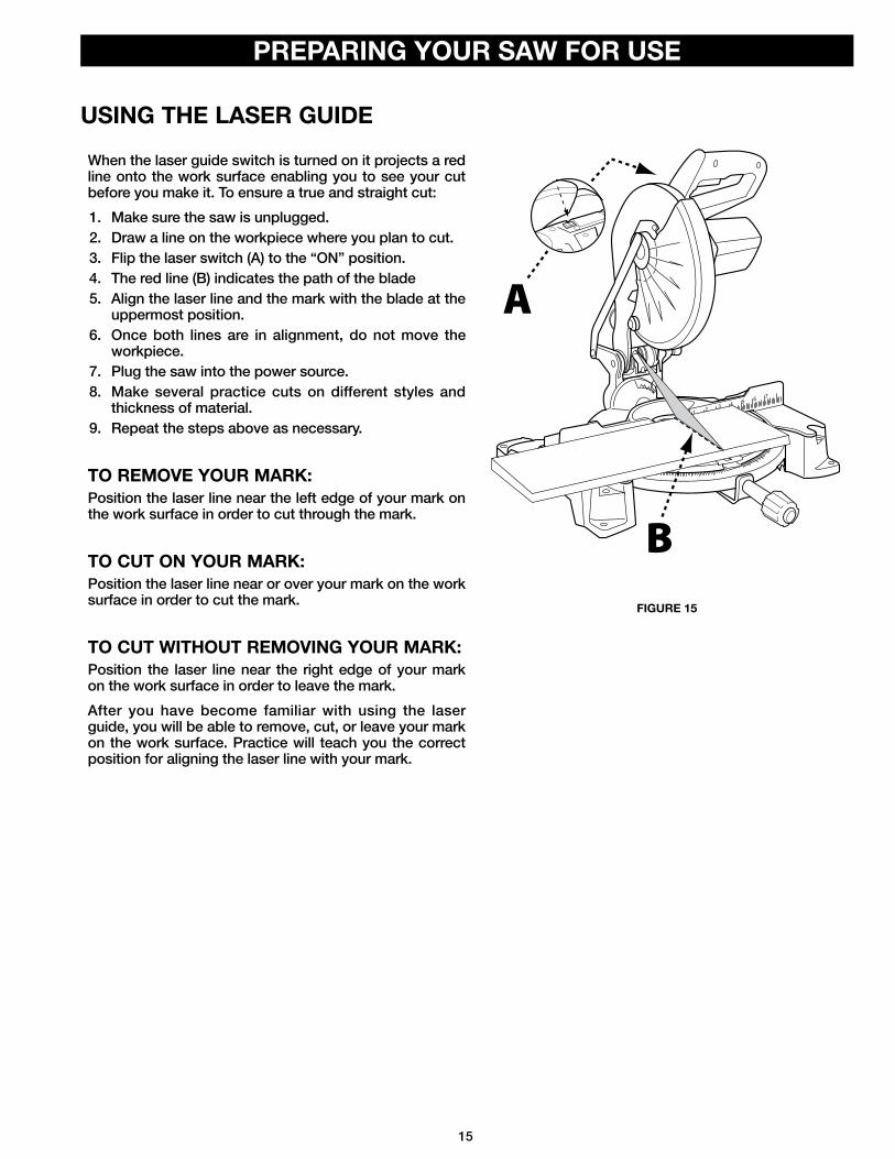
USING THE LASER GUIDE
When the laser guide switch is turned on it projects a red line onto the work surface enabling you to see your cut before you make it. To ensure a true and straight cut: 1. Make sure the saw is unplugged. 2. Draw a line on the workpiece where you plan to cut. 3. Flip the laser switch (A) to the “ON” position.4. The red line (B) indicates the path of the blade5. Align the laser line and the mark with the blade at the
uppermost position. 6. Once both lines are in alignment, do not move the
workpiece.7. Plug the saw into the power source. 8. Make several practice cuts on different styles and
thickness of material. 9. Repeat the steps above as necessary.
TO REMOVE YOUR MARK:Position the laser line near the left edge of your mark on the work surface in order to cut through the mark.
TO CUT ON YOUR MARK:Position the laser line near or over your mark on the work surface in order to cut the mark.
TO CUT WITHOUT REMOVING YOUR MARK:Position the laser line near the right edge of your mark on the work surface in order to leave the mark.After you have become familiar with using the laser guide, you will be able to remove, cut, or leave your mark on the work surface. Practice will teach you the correct position for aligning the laser line with your mark.
1 2 3 4 5 6 7
B
A
FIGURE 15

16
OPERATION
• Do not allow familiarity with tools to make you careless. Remember that a careless fraction of a second is sufficient to inflict serious personal injury.
• Always wear eye protection with side shields and marked to comply with ANSI Z87.1. Failure to do so could result in objects being thrown into your eyes, resulting in possible serious personal injury.
• Do not use any attachments or accessories not recommended by the manufacturer of this tool. The use of attachments or accessories not recommended can result in serious personal injury.
• Before starting any cutting operation, clamp or bolt the compound miter saw to a workbench. Never operate the miter saw on the floor or in a crouched position. Failure to heed this warning can result in serious personal injury.
• To avoid serious personal injury, always tighten the miter lock handle and bevel lock knob securely before making a cut. Failure to do so could result in movement of the control arm or miter table while making a cut.
• To avoid serious personal injury, keep hands outside the no hands zone, at least 3 in. from blade. Never perform any cutting operation freehand (without holding workpiece against the fence). The blade could grab the workpiece if it slips or twists.
• When using a work clamp or C-clamp to secure the workpiece, clamp workpiece on one side of the blade only. The workpiece must remain free on one side of the blade to prevent the blade from binding in workpiece. The workpiece binding the blade will cause motor stalling and kickback. This situation could cause an accident resulting in possible serious personal injury.
• NEVER move the workpiece or make adjustment to any cutting angle while the saw is running and the blade is rotating. Any slip can result in contact with the blade causing serious personal injury.
APPLICATIONSYou may use this tool for the following purposes:
• Bevel cutting and compound cutting for crown moldings, etc. • Cross cutting wood and plastic• Cross cutting for moldings, door casings, picture frames, etc.
NOTE: The blade provided is acceptable for most cutting of lumber and moldings, but for fine joinery cuts or cutting plastic, it is recommended that you use a specialty blade designed for these applications.

17
OPERATION
CROSS CUTSA cross cut is made across the grain of the workpiece. A straight cross cut means the miter scale indicator is set at 0°. For a miter cross cut, the miter scale indicator is set at an angle other than 0°.
Refer to Figure 16.1. Disengage the lock pin (A) and lift saw arm to its full
height.2. For a straight cross cut, skip to step 5. 3. To make a miter cross cut, loosen the miter lock
handle (B). 4. Depress the miter lock plate (C) and rotate the
control arm until the pointer aligns with the desired angle on the miter scale (D) then tighten the miter lock handle securely.
5. Place the workpiece flat on the table with one edge securely against the fence. If the board is warped, place the convex side against the fence. If the concave edge of a board is placed against the fence, the board could collapse on the blade at the end of the cut, jamming the blade.
6. When cutting long pieces of lumber or molding, support the opposite end of the stock with a roller stand or with a work piece support that is level with the table surface. See SUPPORTING LONG WORKPIECES (Page 20).
7. Align cutting line on workpiece with edge of saw blade or laser line.
FIGURE 16
1 2 3 4 5 6 7
B
CDE
A
8. Grasp the stock firmly with one hand and secure it against the fence. Use the optional work clamp (E) or a C-clamp to secure the workpiece when possible.
9. Before turning on the saw, practice the cut to ensure no problems will occur when the cut is made.
10. Hold the saw handle firmly and squeeze the switch trigger. Wait until the blade reaches maximum speed
11. Slowly lower the blade into and through the workpiece.
12. Release the switch trigger and allow the blade to stop rotating before raising the blade out of workpiece.
13. Wait until the electric brake stops blade from turning before removing the workpiece from the table.
BEVEL CUTSA bevel cut is made across the grain with the blade angled to the workpiece. A straight bevel means the miter scale indicator is set at 0° and the bevel scale indicator is set at an angle other than 0°.
COMPOUND MITER CUTSA compound miter cut is a cut made using a miter angle and a bevel angle at the same time. Adjustments of miter and bevel settings are interdependent. Each time you adjust the miter setting you change the effect of the bevel setting. Also, each time you adjust the bevel setting you change the effect of the miter setting.

18
OPERATION
TIPS FOR CUTTING AND SUPPORTING WORKPIECESTIPS FOR CUTTING CROWN MOLDING
• The two edges of the molding that contact the ceiling and the wall are at angles that, when added together, equal exactly 90°. Most crown molding has a top rear angle (the section that fits flat against the ceiling) of 52° and a bottom rear angle (the section that fits flat against the wall) of 38°.
• To accurately cut crown molding for a 90° inside or outside corner, lay the molding with its broad back surface flat on the miter table and against the fence.
• The angles for crown moldings must be very precise. The bevel and miter angles are interdependent; changing one angle changes the other angle as well.
• Since it is very easy for the work piece to shift, all settings should first be tested on scrap molding. Also most walls do not have angles of exactly 90°; therefore, you will need to fine-tune your settings.
• When cutting crown molding the bevel angle should be set at 33.85°. • The miter angle should be set at 31.62° either right or left, depending on the desired cut for the application. See the
chart below for correct angle settings and correct positioning of crown molding on the work table.
Bevel Angle Setting Type of Cut Steps
33.85° Left side, inside corner 1. Top edge of molding against fence2. Miter table set right 31.62°3. Save left end of cut
33.85° Right side, inside corner 1. Bottom edge of molding against fence2. Miter table set left 31.62°3. Save left end of cut
33.85° Left side, outside corner 1. Bottom edge of molding against fence2. Miter table set left 31.62°3. Save right end of cut
33.85° Right side, outside corner 1. Top edge of molding against fence2. Miter table set right 31.62°3. Save right end of cut

19
FIGURE 19
OPERATION
CUTTING WARPED MATERIALWhen attempting to cut warped material, the CONVEX face should be against the fence as shown in Figure 17.
X
1 2 3 4 5 6 7
CLAMPING WIDE WORKPIECESWhen cutting wide work pieces, such as 2 in. x 6 in., clamp the workpiece to the work table using a C-clamp as shown in Figure 19.
Keep clamps away from the path of the blade and blade guard assembly.
Never position a piece of warped material with the CONCAVE face or edge against the fence, as shown in Figure 18. It will pinch the blade near the completion of the cut.
To avoid a kickback and to avoid serious personal injury, never position
the concave edge of bowed or warped material against the fence.
FIGURE 18FIGURE 17

20
OPERATION
ADJUSTMENTS
SUPPORTING LONG WORKPIECESLong workpieces need extra support. Supports should be placed along the workpiece so it does not sag. The support should let the workpiece lay flat on the base of the saw and work table during the cutting operation as shown in Figure 20. Use the optional work clamp or a C-clamp to secure the workpiece to the miter saw table.
Keep clamps away from the path of the blade and blade guard assembly.
Before performing any adjustment, make sure the tool is unplugged from
the power supply. Failure to heed this warning could result in serious personal injury.Your compound miter saw has been properly adjusted at the factory. Due to shipping or normal use, it may be necessary to re-adjust some of the settings. Check the following adjustments periodically to assure proper accuracy and safe operation.
Check for interference between the blade and the throat plate, before
plugging the saw into the power source.
ARM PIVOT The arm of the saw should raise and lower completely and freely. In the lowered position and with the lock pin removed, the arm should rise to the up position by itself. If the saw arm does not raise by itself or if there is play in the pivot joints, it will need to be professionally repaired at an HOMECRAFT® AUTHORIZED SERVICE CENTER. Please call Company’s Customer Care Center at 800-223-7278.
POSITIVE STOP SCREWThe position of the positive stop adjustment screw was set at the factory and normally will not require readjustment. If the blade is not square to the table, the positive stop adjustment screw must be re-adjusted. To adjust refer to Figure 21:1. Unplug the saw.2. Using the Phillips end of the blade wrench, loosen
the positive stop adjustment screw (A) by turning it counterclockwise.
FIGURE 20
FIGURE 21
1 2 3 4 5 6 7
3. Loosen the bevel lock knob (B) by turning it counterclockwise.
4. Square the blade to the miter table as described in the section entitled, ALIGN THE BLADE TO THE TABLE, found on page 14.
5. Retighten bevel lock knob. Recheck blade-to-table alignment.
6. The saw has two scale indicators, one on the bevel scale and one on the miter scale. After squaring adjustments have been made, it may be necessary to loosen the indicator screws and reset them to zero.
NOTE: Use this procedure to check that the blade is square to the table at 0° and 45° angles.
A
B
45º0º

21
ADJUSTMENTS
BEVEL PIVOT With the bevel lock knob loosened, the control arm of the saw should tilt easily from 0° and 45°. If it does not or if there is play in the pivot, the saw must be repaired by a HOMECRAFT® AUTHORIZED SERVICE CENTER.
Laser radiation. Avoid direct eye contact with light source.
LASER GUIDERefer to Figure 22.1. Secure a piece of scrap material to the table
surface using the work clamp or a C-clamp. 2. Plug the saw into the power source and make a
slight cut to score the wood.3. Release the switch trigger and make sure the blade
comes to a full stop, then raise the saw arm to the upright position.
4. Unplug the saw. Do not remove the scrap piece. 5. Turn on the laser switch (A). If properly aligned, the
laser should align with the left edge of the partial cut you just made.
6. If the laser does not align with the left edge of the cut, loosen the laser adjustment screw (B) using the Phillips end of the supplied blade wrench and reposition the laser.
7. Once aligned, tighten the screw using the blade wrench and recheck alignment of laser line to cut made in scrap material.
FIGURE 22
1 2 3 4 5 6 7B
A

22
MAINTENANCE
BRUSH REPLACEMENT
To reduce the risk of injury, turn unit off and disconnect it from power
source before cleaning or servicing, before installing and removing accessories, before adjusting and when making repairs. An accidental start-up can cause injury.
KEEP MACHINE CLEANPeriodically blow out all air passages with dry compressed air. All plastic parts should be cleaned with a soft damp cloth. NEVER use solvents to clean plastic parts. They could possibly dissolve or otherwise damage the material. Wear certified safety equipment for eye, hearing and respiratory protection while using compressed air.Empty dust bag frequently.
When servicing, use only identical replacement parts. Use of any other
parts may create a hazard or cause product damage.
GENERAL MAINTENANCEAvoid using solvents when cleaning plastic parts. Most plastics are susceptible to damage from various types
The motor on this saw features externally accessible brush assemblies that should be periodically checked for wear. If the brushes need replaced, refer to Figure 23 and proceed as follows.
1. Unplug the saw.
Failure to unplug the saw could result in accidental starting causing serious personal injury.
2. Using a screwdriver, carefully remove the brush cap (A)
NOTE: Remove the cap slowly. The brush assembly is spring-loaded and will pop out once the cap is removed. 3. Remove brush assembly (B).4. Inspect both brushes. If either has less than 1/4 in.
length of carbon remaining, both brushes should be replaced.
NOTE: Do not replace one side without replacing the other.5. Insert both brushes into the brush tube (C),
making sure the curvature of the brushes matches curvature of motor. Brush assembly should move freely within the tube.
6. Carefully replace the brush cap, ensuring that it is not cross-threaded.
7. Tighten brush cap securely. Do not over tighten.
FIGURE 23
of commercial solvents and may be damaged by their use. Use clean clothes to remove dirt, dust, oil, grease, etc.
Do not at any time let brake fluids, g a s o l i n e , p e t ro l e u m - b a s e d
products, penetrating oils, etc., come in contact with plastic parts. Chemicals can damage, weaken or destroy plastic which may result in serious personal injury.Electric tools used on fiberglass material, wallboard, spackling compounds, or plaster are subject to accelerated wear and possible premature failure because the fiberglass chips and grindings are highly abrasive to bearings, brushes, commutator, etc. Consequently, we do not recommended using this tool for extended work on these types of materials. However, if you do work with any of these materials, it is extremely important to clean the tool using compressed air.
LUBRICATIONAll of the bearings in this tool are lubricated with a sufficient amount of high-grade lubricant for the life of the unit under normal operating conditions. Therefore, no further lubrication is required.
AC
B

23
TROUBLESHOOTING
ACCESSORIES
PARTS, SERVICE OR WARRANTY ASSISTANCE
FAILURE TO STARTIf your machine fails to start, check to make sure the prongs on the cord plug are making good contact in the receptacle. Also, check for blown fuses or open circuit breakers in your power supply line. If the saw still does not start, call Company's Customer Care Center at 1-800-223-7278
For accessories please visit our Web Site www.DeltaMachinery.com for an online catalog or for the name or your nearest supplier.
Since accessories other than those offered by DELTA® have not been tested with this product, use of such accessories could be hazardous. For safest operation, only DELTA® /Homecraft®
recommended accessories should be used with this product.
All DELTA®/Homecraft® Machines and accessories are manufactured to high quality standards and are serviced by a network of DELTA® Authorized Service Centers. To obtain additional information regarding your product or to obtain parts, service, warranty assistance, or the location of the nearest service center, please call 1-800-223-7278.
Homecraft® Three Year Limited Warranty1. WHAT IS COVERED. Delta Power Equipment Corporation (“Company”) will repair or replace, at its option, any new or factory
refurbished HOMECRAFT® machine or service part which is purchased at retail in the United States or Canada and which in normal use has proven to be defective in workmanship or material, subject to the conditions stated in this Limited Warranty. This Limited Warranty covers only materials and labor. All transportation costs are Customer’s responsibility.
2. WARRANTY PERIOD. All warranty claims must be submitted within three years from the date of retail purchase. For all service parts and factory refurbished HOMECRAFT® machines, the warranty period is 180 days.
3. HOW TO OBTAIN SERVICE. To obtain warranty service, you must return the defective product, at your expense, to a service center authorized by Company to perform warranty service (a “HOMECRAFT® Authorized Service Center”) within the applicable warranty period, together with acceptable proof of purchase, such as your original receipt bearing the date of purchase, or product registration number. Company reserves the right to restrict warranty claim service to the country where the purchase was made and/or to charge for the cost to export service parts or provide warranty service in a different country. On-line purchases are deemed made in the United States. For the location of your nearest HOMECRAFT® Authorized Service Center, call Company’s Customer Care Center at (800) 223-7278.
4. EXCLUSIONS. • Company does not offer any warranty on products purchased in used or damaged condition.• Company does not warranty any products purchased outside the United States or Canada• Company will not be responsible for any damage that has resulted from normal wear, misuse, abuse or any repair or alteration
made by anyone other than a HOMECRAFT® Authorized Service Center or a designated representative of Company’s Customer Care Center.
• All IMPLIED WARRANTIES are expressly limited to the warranty period identified above.• Under no circumstances will Company be liable for INCIDENTAL OR CONSEQUENTIAL damages.• This limited warranty is Company’s sole warranty and sets forth the customer’s exclusive remedy with respect to defective
products; all other warranties, express or implied, whether of merchantability, fitness for purpose, or otherwise, are expressly disclaimed by Company, except as stated above.
Some states do not allow the exclusion or limitation of incidental or consequential damages, or the limitation of implied warranties, so the above limitations or exclusions may not apply to you. This warranty gives you specific legal rights and you may have other rights which vary in certain states or provinces. For further details of warranty coverage and warranty repair information, call (800) 223-7278. To register your products online, we encourage you to visit our website and register for a FREE DELTA Member Account at http://www.deltamachinery.com/register.

PARTS, SERVICE OR WARRANTY ASSISTANCEREPLACEMENT PARTSUse only identical replacement parts. For a parts list or to order parts, visit our website at www.DeltaMachinery.com/service. You can also order parts from your nearest Authorized Warranty Service Center or by calling Technical Service Manager at 1-800-223-7278 to receive personalized support from one of our highly-trained representatives.Free Warning Label ReplacementIf your warning labels become illegible or are missing, call 1-800-223-7278 for a free replacement.
SERVICE AND REPAIRSAll quality tools will eventually require servicing and/or replacement of parts. For information about DELTA® Power Equipment Corporation, its factory-owned branches, or to locate an Authorized Warranty Service Center, visit our website at www.DeltaMachinery.com/service or call Customer Care at 1-800-223-7278. All repairs made by our service centers are fully guaranteed against defective material and workmanship. We cannot guarantee repairs made or attempted by others. By calling this number you can also find answers to most frequently asked questions 24 hours/day.You can also write to us for information at DELTA® Power Equipment Corporation, 99 Roush St, Anderson, SC 29625-3113 - Attention: Technical Service Manager. Be sure to include all of the information shown on the nameplate of your saw (model number, type, serial number, date code, etc.)
24

25

99 ROUSH ST ANDERSON, SC 29625-3113
(800) 223-7278 www.DeltaMachinery.com
Copyright © 2013 DELTA® Power Equipment Corporation DPEC002900 11-1-13


![DEWALT DW708 12 Double-Bevel Sliding Compound Miter Manual[1]](https://img.pdfslide.us/doc/110x75/55cf9ded550346d033afe25e/dewalt-dw708-12-double-bevel-sliding-compound-miter-manual1.jpg)