Embed Size (px)
Citation preview
© 2010 Cisco Systems, Inc. All rights reserved. This document is Cisco Public Information.
Chapter 7
10 Gigabit Ethernet Connectivity with Microsoft Windows Servers

Design Guide
© 2010 Cisco Systems, Inc. All rights reserved. This document is Cisco Public Information. Page 2 of 17
Contents
Server Connectivity Technology ................................................................................................................................3 Operating Systems Support .......................................................................................................................................3 Typical Teaming and Bonding Capabilities...............................................................................................................4
Teaming with PortChannels ......................................................................................................................................6 Transmit Load Balancing ..........................................................................................................................................6
Typical Teaming Configuration Steps........................................................................................................................7 Creating a PortChannel Team ..................................................................................................................................7 Assigning VLANs ....................................................................................................................................................10
Tuning Servers with 10 Gigabit Ethernet Adapters ................................................................................................11 PCIe Connectivity ...................................................................................................................................................11 Offloads ..................................................................................................................................................................11 OS Tuning...............................................................................................................................................................12 Receive Mode Compared to Transmit Mode...........................................................................................................13 Tuning Example ......................................................................................................................................................13
Design Guide
© 2010 Cisco Systems, Inc. All rights reserved. This document is Cisco Public Information. Page 3 of 17
Server Connectivity Technology
A server connects to an access switch with multiple network adapter ports. For a typical rack-mountable server, a
typical configuration consists of the following ports:
● Integrated lights-out (iLO) management port: Replaces the console and provides the capability to turn the
servers on and off
● Dual lights-out management (LOM) port: Connected redundantly to the management network
● Quad-port Gigabit Ethernet adapter: Used for production traffic
● Two single-port host bus adapters (HBAs) or single dual-port HBA: Used for Fibre Channel connectivity
Modern installations consist of servers adopting 10 Gigabit Ethernet adapters with or without the capability to support
Fibre Channel over Ethernet (FCoE) as follows:
● iLO
● Dual LOM
● Dual-port 10 Gigabit Ethernet adapter: Used for production traffic; may or may not include support for FCoE
(unified I/O)
● (Optional) Two single-port HBAs or single dual-port HBA: used for Fibre Channel connectivity if the 10
Gigabit Ethernet adapter does not provide FCoE support
Operating Systems Support
Different operating systems handle multiport adapters and multiple network interface cards (NICs) in different ways:
● Microsoft Windows: Requires NIC vendors’ teaming software (and drivers) to bundle the network adapters
together
● Linux operating systems: Offer built-in support for bonding (http://linux-ip.net/html/ether-bonding.html); NIC
vendors also offer specific drivers tailored for their adapters that may provide better performance than the
built-in bonding implementation
● Virtualized servers: Handle multiple NICs natively without the need to install any teaming software on the
guest OS; virtualized server networking is beyond the scope of this guide
For Microsoft products, if you have Intel adapters, you can deploy Intel PROSet with Advanced Network Services
(ANS). For HP products (typically operating on a Broadcom adapter), you can use the HP Network Configuration
Utility (NCU):
● Intel: Intel adapters can be teamed with ANS (http://www.intel.com/support/network/sb/cs-009747.htm,
http://www.intel.com/support/network/adapter/ans/). Teaming configurations can be performed from the
Properties tab by clicking on the Configure button or by using the Visual Basic scripts in C:\Program
Files\Intel\NCS2\Scripts\.
● HP: HP adapters can be teamed with HP NCU
(http://bizsupport.austin.hp.com/bc/docs/support/SupportManual/c01415139/c01415139.pdf).
Teaming software from different vendors may be incompatible with each other. For example, if your server
deployment consists of built-in Broadcom LOMs and Intel adapters, then you may not be able to use HP NCU or Intel
PROSet for all the adapters concurrently.

Design Guide
Another important factor to consider when deploying teaming is that sometimes teaming software interferes with
Small Computer System Interface over IP (iSCSI) support. In some cases, then, you need to flash network adapters
to reset the iSCSI boot configuration and set it to preexecution environment (PXE) boot before you can use the NIC
teaming configurations. In the case of Intel controllers, you can use utilities such as the Intel Boot Agent Utility, ibautil,
from a bootable CD to flash the adapter: see
http://downloadcenter.intel.com/Detail_Desc.aspx?agr=Y&DwnldID=8242.
Typical Teaming and Bonding Capabilities
Network adapters connect to the network in a redundant fashion. This redundancy increases performance and
provides high availability. Two main options are available for servers to support redundant connectivity to the
network:
● Routing: An IP address is assigned to each NIC and a routing protocol is run on the server. This option is not
commonly used and is not recommended.
● NIC teaming: The network adapter manufacturer provides software that, together with the driver, bundles the
NICs and exposes them to the operating system as a single entity. Figure 1 shows an example in which Local
Area Connection 9 and Local Area Connection 11 have been teamed and are presented to the OS as a single
adapter, which is listed as Local Area Connection 13.
Figure 1. Example of Teaming Configuration
Typical teaming options include the following:
● Fault tolerance (adapter): Only one of the teamed NICs transmits and receives; all remaining NICs are on
standby. The user can optionally define the order of preference to set the NIC that becomes primary. In Figure
2, this is option (a).
● Load balancing ((transmit or adaptive): Outgoing traffic is load-balanced across all teamed NICs, while the
incoming traffic is received only on one NIC. Figure 3 illustrates this type of configuration. Adapter 9 (with a
MAC address ending in .07cc) and adapter 11 (with a MAC address ending in .07ce) are teamed, and adapter
9 is preferred for the receive direction of the traffic (which means that Adapter 9 answers Address Resolution
Protocol [ARP] requests). The load-balancing method hashes traffic based on the destination IP address. In
Figure 2, this is option (b).
© 2010 Cisco Systems, Inc. All rights reserved. This document is Cisco Public Information. Page 4 of 17
Design Guide
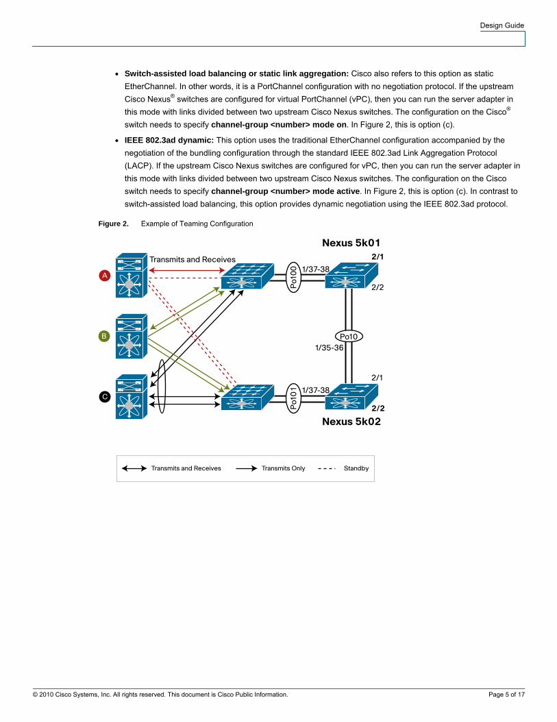
● Switch-assisted load balancing or static link aggregation: Cisco also refers to this option as static
EtherChannel. In other words, it is a PortChannel configuration with no negotiation protocol. If the upstream
Cisco Nexus® switches are configured for virtual PortChannel (vPC), then you can run the server adapter in
this mode with links divided between two upstream Cisco Nexus switches. The configuration on the Cisco®
switch needs to specify channel-group <number> mode on. In Figure 2, this is option (c).
● IEEE 802.3ad dynamic: This option uses the traditional EtherChannel configuration accompanied by the
negotiation of the bundling configuration through the standard IEEE 802.3ad Link Aggregation Protocol
(LACP). If the upstream Cisco Nexus switches are configured for vPC, then you can run the server adapter in
this mode with links divided between two upstream Cisco Nexus switches. The configuration on the Cisco
switch needs to specify channel-group <number> mode active. In Figure 2, this is option (c). In contrast to
switch-assisted load balancing, this option provides dynamic negotiation using the IEEE 802.3ad protocol.
Figure 2. Example of Teaming Configuration
© 2010 Cisco Systems, Inc. All rights reserved. This document is Cisco Public Information. Page 5 of 17

Design Guide
Figure 3. Example of Teaming Configuration
Teaming with PortChannels
Some terminology differs from vendor to vendor. For example, Intel uses the following terminology:
● Static link aggregation: In Cisco terminology, this is a static PortChannel (EtherChannel): channel-group
mode on.
● Dynamic link aggregation: In Cisco terminology, this is a dynamic PortChannel (EtherChannel): channel-
group mode active.
For PortChannels, HP NCU uses this terminology:
● Switch-assisted load balancing: In Cisco terminology, this is a static PortChannel (EtherChannel): channel-
group mode on.
● IEEE 802.3ad dynamic: In Cisco terminology, this is a dynamic PortChannel (EtherChannel): channel-group
mode active.
Additional teaming capabilities include the following:
● Capability to define VLANs: Each additional VLAN on an adapter is presented to the OS as an individual
local-area connection.
● Capability to define a VLAN on top of a teamed adapter: This option enables redundant connectivity from
the server to the network and creation of a virtual network adapter on every VLAN.
Transmit Load Balancing
Transmit load balancing (TLB) can be used when the upstream switches do not support vPC. It has the peculiar
behavior of using multiple links for sending and only one link for receiving.
This behavior can be seen in the MAC address table of the two switches to which a server configured in this manner
is connected. As you can see, the server uses two different MAC addresses for sending traffic, and the ARP table of
the router learns only one of the two MAC addresses:
tc-nexus7k01-vdc2# show ip arp vlan 60
IP ARP Table
Total number of entries: 3
© 2010 Cisco Systems, Inc. All rights reserved. This document is Cisco Public Information. Page 6 of 17
Design Guide
Address Age MAC Address Interface
10.60.0.10 00:00:59 001f.290d.07cc Vlan60
tc-nexus5k01# show mac address-table int eth1/12
Legend:
* - primary entry, G - Gateway MAC, (R) - Routed MAC
age - seconds since last seen,+ - primary entry using vPC Peer-Link
VLAN MAC Address Type age Secure NTFY Ports
---------+-----------------+--------+---------+------+------+----------------
* 60 001f.290d.07cc dynamic 0 False False Eth1/12
tc-nexus5k02-vdc2# show mac address-table int eth1/12
Legend:
* - primary entry, G - Gateway MAC, (R) - Routed MAC
age - seconds since last seen,+ - primary entry using vPC Peer-Link
VLAN MAC Address Type age Secure NTFY Ports
---------+-----------------+--------+---------+------+------+----------------
* 60 001f.290d.07ce dynamic 0 False False Eth1/12
Typical Teaming Configuration Steps
This section shows a sample configuration for NIC teaming.
Creating a PortChannel Team
Follow these configuration steps:
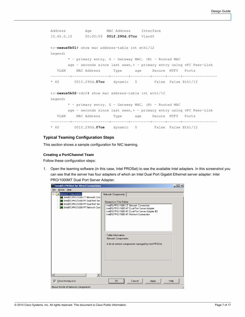
1. Open the teaming software (in this case, Intel PROSet) to see the available Intel adapters. In this screenshot you
can see that the server has four adapters of which an Intel Dual Port Gigabit Ethernet server adapter: Intel
PRO/1000MT Dual Port Server Adapter.
© 2010 Cisco Systems, Inc. All rights reserved. This document is Cisco Public Information. Page 7 of 17
Design Guide
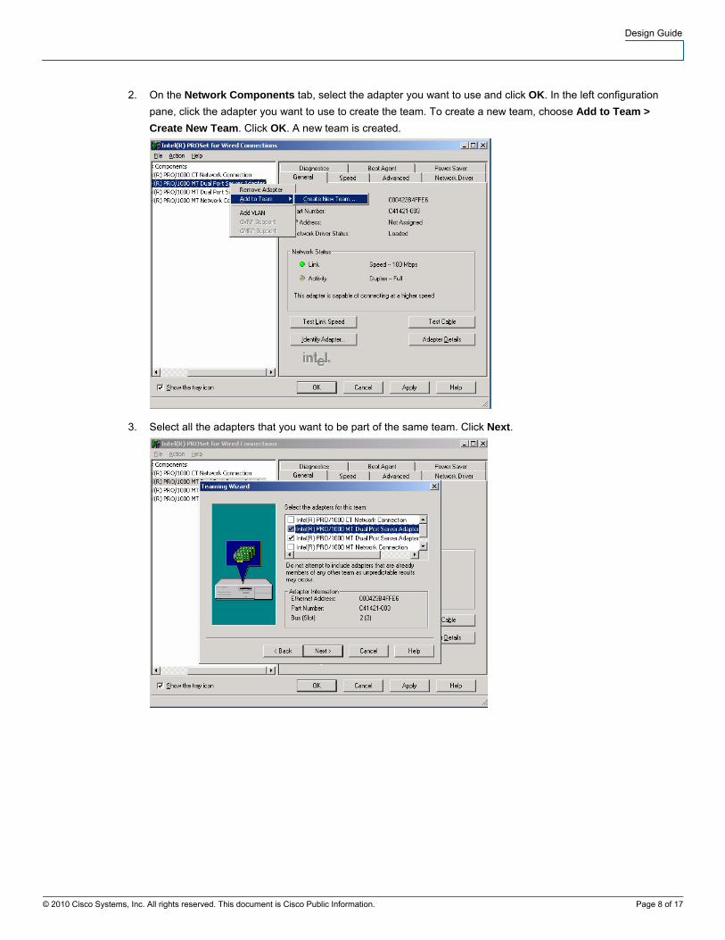
2. On the Network Components tab, select the adapter you want to use and click OK. In the left configuration
pane, click the adapter you want to use to create the team. To create a new team, choose Add to Team >
Create New Team. Click OK. A new team is created.
3. Select all the adapters that you want to be part of the same team. Click Next.
© 2010 Cisco Systems, Inc. All rights reserved. This document is Cisco Public Information. Page 8 of 17
Design Guide
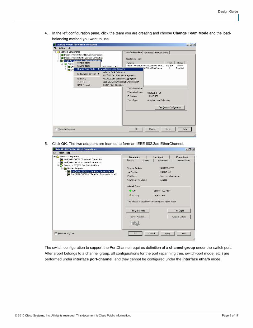
4. In the left configuration pane, click the team you are creating and choose Change Team Mode and the load-
balancing method you want to use.
5. Click OK. The two adapters are teamed to form an IEEE 802.3ad EtherChannel.
The switch configuration to support the PortChannel requires definition of a channel-group under the switch port.
After a port belongs to a channel group, all configurations for the port (spanning tree, switch-port mode, etc.) are
performed under interface port-channel, and they cannot be configured under the interface etha/b mode.
© 2010 Cisco Systems, Inc. All rights reserved. This document is Cisco Public Information. Page 9 of 17
Design Guide
If the PortChannel is spread across two Cisco Nexus 5000 or 7000 Series Switches, the configuration of the
PortChannel looks as follows:
interface port-channel60
switchport
switchport mode access
switchport access vlan 60
vpc 60
Assigning VLANs
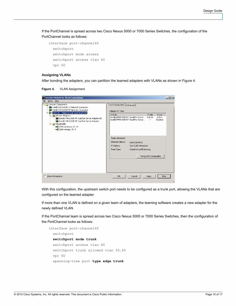
After bonding the adapters, you can partition the teamed adapters with VLANs as shown in Figure 4.
Figure 4. VLAN Assignment
With this configuration, the upstream switch port needs to be configured as a trunk port, allowing the VLANs that are
configured on the teamed adapter.
If more than one VLAN is defined on a given team of adapters, the teaming software creates a new adapter for the
newly defined VLAN.
If the PortChannel team is spread across two Cisco Nexus 5000 or 7000 Series Switches, then the configuration of
the PortChannel looks as follows:
interface port-channel60
switchport
switchport mode trunk
switchport access vlan 60
switchport trunk allowed vlan 50,60
vpc 60
spanning-tree port type edge trunk
© 2010 Cisco Systems, Inc. All rights reserved. This document is Cisco Public Information. Page 10 of 17
Design Guide
© 2010 Cisco Systems, Inc. All rights reserved. This document is Cisco Public Information. Page 11 of 17
Tuning Servers with 10 Gigabit Ethernet Adapters
The main steps you need to follow to make sure that the 10 Gigabit Ethernet–connected server is configured properly
and takes advantage of the available bandwidth are listed here in order of priority:
● Verify that the adapter is installed in a proper PCI Express (PCIe) bus with a speed greater than or equal to
8X.
● Make sure that the traffic generation and reception is distributed across all the available cores by selecting the
appropriate receive-side scaling (RSS) configuration. For example, if you have four cores, then you should
configure four RSS queues.
● Make sure that large segment offload and TCP checksum offloading are enabled, and if the option exists,
make sure that selective acknowledgement in hardware is enabled.
● Make sure that all options—large segment offload, TCP offload, RSS, TCP scaling, etc.—are enabled in the
same way in the operating system (in Microsoft Windows Server 2008, you can check this configuration by
using the command netsh int tcp show global).
Failure to do follow these steps may result in reduced performance and greater CPU utilization than is needed.
PCIe Connectivity
10 Gigabit Ethernet adapters need to be installed in the correct PCIe slot to avoid an unnecessary bottleneck in the
system. The minimum requirement to achieve 10-Gbps throughput in one direction is to install the card in a PCIe 8X
slot.
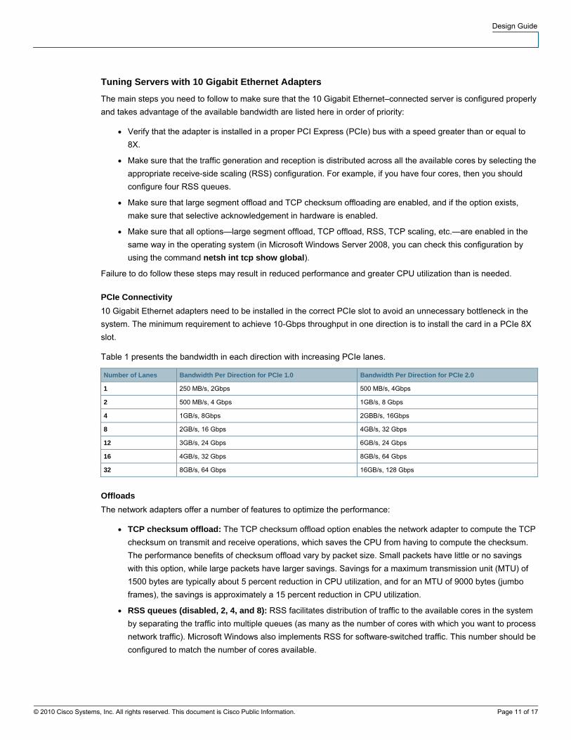
Table 1 presents the bandwidth in each direction with increasing PCIe lanes.
Number of Lanes Bandwidth Per Direction for PCIe 1.0 Bandwidth Per Direction for PCIe 2.0
1 250 MB/s, 2Gbps 500 MB/s, 4Gbps
2 500 MB/s, 4 Gbps 1GB/s, 8 Gbps
4 1GB/s, 8Gbps 2GBB/s, 16Gbps
8 2GB/s, 16 Gbps 4GB/s, 32 Gbps
12 3GB/s, 24 Gbps 6GB/s, 24 Gbps
16 4GB/s, 32 Gbps 8GB/s, 64 Gbps
32 8GB/s, 64 Gbps 16GB/s, 128 Gbps
Offloads
The network adapters offer a number of features to optimize the performance:
● TCP checksum offload: The TCP checksum offload option enables the network adapter to compute the TCP
checksum on transmit and receive operations, which saves the CPU from having to compute the checksum.
The performance benefits of checksum offload vary by packet size. Small packets have little or no savings
with this option, while large packets have larger savings. Savings for a maximum transmission unit (MTU) of
1500 bytes are typically about 5 percent reduction in CPU utilization, and for an MTU of 9000 bytes (jumbo
frames), the savings is approximately a 15 percent reduction in CPU utilization.
● RSS queues (disabled, 2, 4, and 8): RSS facilitates distribution of traffic to the available cores in the system
by separating the traffic into multiple queues (as many as the number of cores with which you want to process
network traffic). Microsoft Windows also implements RSS for software-switched traffic. This number should be
configured to match the number of cores available.
Design Guide
● Large send offload: When this option is enabled, the operating system can pass large message sizes to the
network adapter, and the network adapter will slice them up based on the maximum segment size (MSS),
which relieves the CPU from the task of TCP segmentation. The TCP large send offload option allows the
TCP layer to build a TCP message of up to 64 KB and send it in one call down the stack through IP and the
Ethernet device driver.
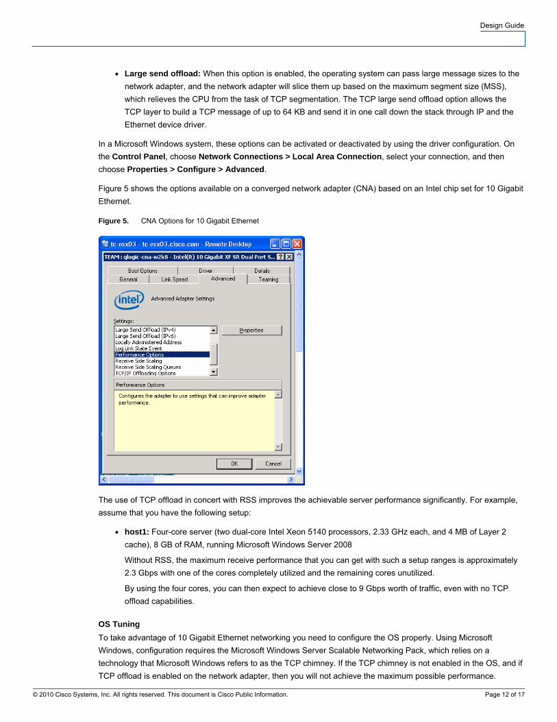
In a Microsoft Windows system, these options can be activated or deactivated by using the driver configuration. On
the Control Panel, choose Network Connections > Local Area Connection, select your connection, and then
choose Properties > Configure > Advanced.
Figure 5 shows the options available on a converged network adapter (CNA) based on an Intel chip set for 10 Gigabit
Ethernet.
Figure 5. CNA Options for 10 Gigabit Ethernet
The use of TCP offload in concert with RSS improves the achievable server performance significantly. For example,
assume that you have the following setup:
● host1: Four-core server (two dual-core Intel Xeon 5140 processors, 2.33 GHz each, and 4 MB of Layer 2
cache), 8 GB of RAM, running Microsoft Windows Server 2008
Without RSS, the maximum receive performance that you can get with such a setup ranges is approximately
2.3 Gbps with one of the cores completely utilized and the remaining cores unutilized.
By using the four cores, you can then expect to achieve close to 9 Gbps worth of traffic, even with no TCP
offload capabilities.
OS Tuning
To take advantage of 10 Gigabit Ethernet networking you need to configure the OS properly. Using Microsoft
Windows, configuration requires the Microsoft Windows Server Scalable Networking Pack, which relies on a
technology that Microsoft Windows refers to as the TCP chimney. If the TCP chimney is not enabled in the OS, and if
TCP offload is enabled on the network adapter, then you will not achieve the maximum possible performance.
© 2010 Cisco Systems, Inc. All rights reserved. This document is Cisco Public Information. Page 12 of 17
Design Guide
© 2010 Cisco Systems, Inc. All rights reserved. This document is Cisco Public Information. Page 13 of 17
For more information about TCP chimney and RSS, refer to the following publications:
● Microsoft Windows Server 2003: http://support.microsoft.com/kb/912222
● Microsoft Windows Server 2008: http://support.microsoft.com/kb/951037
The Microsoft Windows Server Scalable Network Pack controls these parameters (as well as others):
● TCP Chimney Offload: This parameter is enabled in the registry editor as EnableTCPChimney = 1. If TCP
chimney is not enabled, and if the full TCP stack is offloaded in the network adapter card, then TCP traffic has
an oscillating behavior. If TCP chimney is enabled and the network adapter card has TCP offload disabled,
then TCP traffic is dropped.
● RSS: This parameter allows distribution of the traffic to the cores that are present in the system. For example,
with four cores, you should configure the driver for four queues, and you should configure EnableRSS = 1 in
the registry editor. If RSS is not enabled, Microsoft Windows by default uses only one core for TCP/IP
processing.
● NetDMA: This parameter is controlled in the registry by the setting called EnableTCPA = 1. This feature
allows direct memory access between the adapter and the CPU.
Some of these settings can be configured using the command-line interface (CLI) instead of the registry editor,
providing the advantage of not requiring a reboot (the netsh CLI shows all the configurations available):
● Microsoft Windows Server 2003: netsh int ip set chimney ENABLED
● Microsoft Windows Server 2008: netsh int tcp set global chimney=enabled
To verify that TCP chimney and hardware offloads are working, enter the command netstat –t. Connections listed as
OFFLOADED are TCP offloaded by the NIC, and connections listed INHOST are handled by the CPU.
Receive Mode Compared to Transmit Mode
Operating systems in general offer less performance in receive mode (traffic received by the server) than in transmit
mode (traffic sent by the server), so in typical performance tests with two machines with identical hardware, the
sender can easily overwhelm the receiver, causing it to drop frames. To make sure that the sender and receiver do
not throttle the performance because of the drops, you should make sure that selective acknowledgement (SACK) is
enabled in the adapter and the operating system.
When you are operating with TCP offload disabled, the TCP/IP stack in Microsoft Windows automatically implements
SACK.
When you are operating with TCP offload enabled and the TCP/IP stack is implemented in hardware on the network
adapter card, you may need to verify that SACK is enabled at the network adapter layer.
Tuning Example
Assume that you have a setup with a sender and receiver as follows:
● host1: Four-core machine, 8 GB of RAM, running Microsoft Windows Server 2008
● host2: Two-core machine, 4 GB of RAM, running Microsoft Windows Server 2003
You have checked that the network adapters are plugged into an 8X slot, and you have enabled all the parameters
on the driver as recommended in this chapter, but you reach a maximum performance of only approximately 4 Gbps.
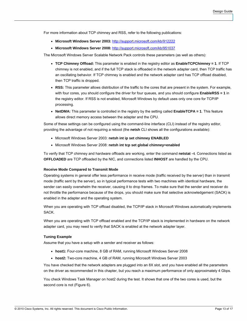
You check Windows Task Manager on host2 during the test. It shows that one of the two cores is used, but the
second core is not (Figure 6).
Design Guide
Figure 6. Windows Task Manager
This result seems to indicate that the OS is not operating according to the RSS configuration.
You may want to check the following registry entries (Microsoft Windows Server 2003):
HKEY_LOCAL_MACHINE\SYSTEM\CurrentControlSet\Services\Tcpip\Parameters
Alternatively, enter the following command (Microsoft Windows Server 2008):
netsh int tcp show global
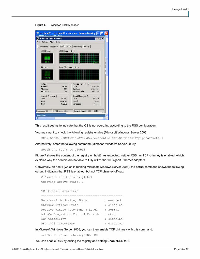
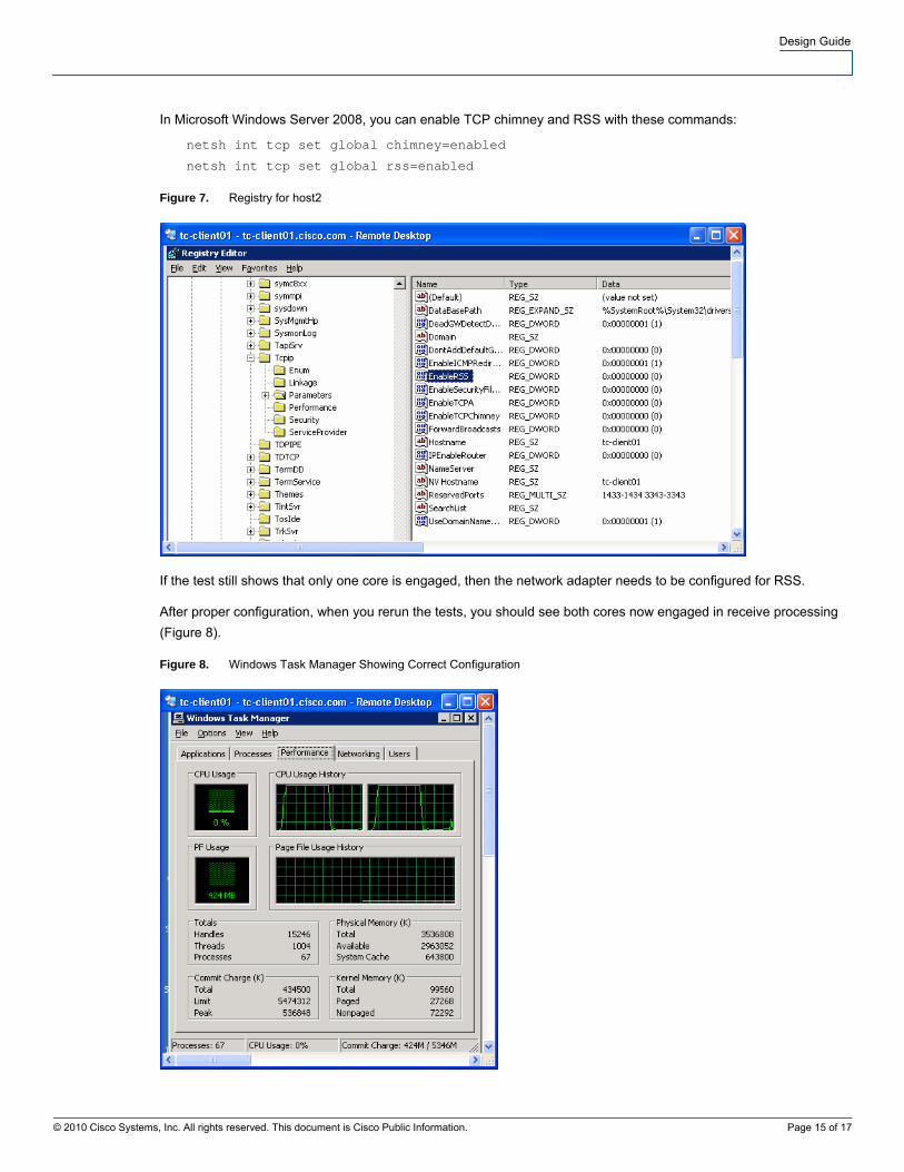
Figure 7 shows the content of the registry on host2. As expected, neither RSS nor TCP chimney is enabled, which
explains why the servers are not able to fully utilize the 10 Gigabit Ethernet adapters.
Conversely, on host1 (which is running Microsoft Windows Server 2008), the netsh command shows the following
output, indicating that RSS is enabled, but not TCP chimney offload:
C:\>netsh int tcp show global
Querying active state...
TCP Global Parameters
----------------------------------------------
Receive-Side Scaling State : enabled
Chimney Offload State : disabled
Receive Window Auto-Tuning Level : normal
Add-On Congestion Control Provider : ctcp
ECN Capability : disabled
RFC 1323 Timestamps : disabled
In Microsoft Windows Server 2003, you can then enable TCP chimney with this command:
netsh int ip set chimney ENABLED
You can enable RSS by editing the registry and setting EnableRSS to 1.
© 2010 Cisco Systems, Inc. All rights reserved. This document is Cisco Public Information. Page 14 of 17
Design Guide
In Microsoft Windows Server 2008, you can enable TCP chimney and RSS with these commands:
netsh int tcp set global chimney=enabled
netsh int tcp set global rss=enabled
Figure 7. Registry for host2
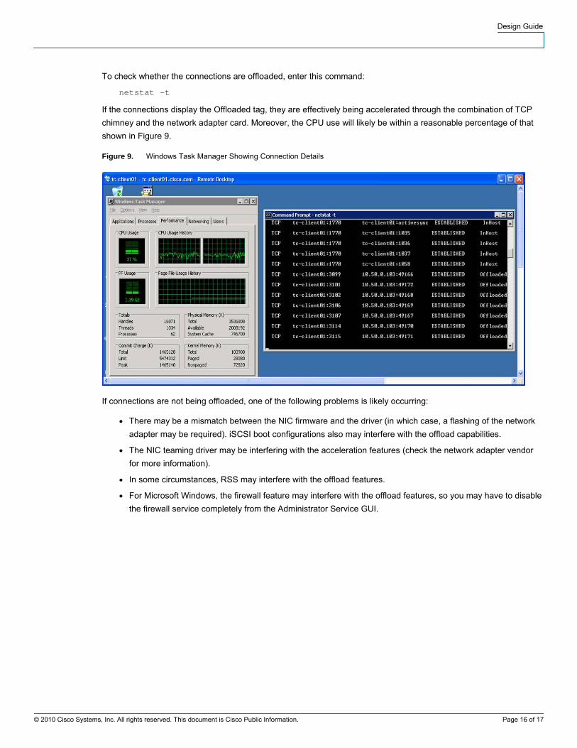
If the test still shows that only one core is engaged, then the network adapter needs to be configured for RSS.
After proper configuration, when you rerun the tests, you should see both cores now engaged in receive processing
(Figure 8).
Figure 8. Windows Task Manager Showing Correct Configuration
© 2010 Cisco Systems, Inc. All rights reserved. This document is Cisco Public Information. Page 15 of 17
Design Guide
To check whether the connections are offloaded, enter this command:
netstat –t
If the connections display the Offloaded tag, they are effectively being accelerated through the combination of TCP
chimney and the network adapter card. Moreover, the CPU use will likely be within a reasonable percentage of that
shown in Figure 9.
Figure 9. Windows Task Manager Showing Connection Details
If connections are not being offloaded, one of the following problems is likely occurring:
● There may be a mismatch between the NIC firmware and the driver (in which case, a flashing of the network
adapter may be required). iSCSI boot configurations also may interfere with the offload capabilities.
● The NIC teaming driver may be interfering with the acceleration features (check the network adapter vendor
for more information).
● In some circumstances, RSS may interfere with the offload features.
● For Microsoft Windows, the firewall feature may interfere with the offload features, so you may have to disable
the firewall service completely from the Administrator Service GUI.
© 2010 Cisco Systems, Inc. All rights reserved. This document is Cisco Public Information. Page 16 of 17

Design Guide
Cisco has more than 200 offices worldwide. Addresses, phone numbers, and fax numbers are listed on the Cisco Website at www.cisco.com/go/offices.
CCDE, CCENT, CCSI, Cisco Eos, Cisco HealthPresence, Cisco IronPort, the Cisco logo, Cisco Nurse Connect, Cisco Pulse, Cisco SensorBase, Cisco StackPower, Cisco StadiumVision, Cisco TelePresence, Cisco Unified
Computing System, Cisco WebEx, DCE, Flip Channels, Flip for Good, Flip Mino, Flipshare (Design), Flip Ultra, Flip Video, Flip Video (Design), Instant Broadband, and Welcome to the Human Network are trademarks; Changing
the Way We Work, Live, Play, and Learn, Cisco Capital, Cisco Capital (Design), Cisco:Financed (Stylized), Cisco Store, Flip Gift Card, and One Million Acts of Green are service marks; and Access Registrar, Aironet, AllTouch,
AsyncOS, Bringing the Meeting To You, Catalyst, CCDA, CCDP, CCIE, CCIP, CCNA, CCNP, CCSP, CCVP, Cisco, the Cisco Certified Internetwork Expert logo, Cisco IOS, Cisco Lumin, Cisco Nexus, Cisco Press, Cisco Systems,
Cisco Systems Capital, the Cisco Systems logo, Cisco Unity, Collaboration Without Limitation, Continuum, EtherFast, EtherSwitch, Event Center, Explorer, Follow Me Browsing, GainMaker, iLYNX, IOS, iPhone, IronPort, the
IronPort logo, Laser Link, LightStream, Linksys, MeetingPlace, MeetingPlace Chime Sound, MGX, Networkers, Networking Academy, PCNow, PIX, PowerKEY, PowerPanels, PowerTV, PowerTV (Design), PowerVu, Prisma,
ProConnect, ROSA, SenderBase, SMARTnet, Spectrum Expert, StackWise, WebEx, and the WebEx logo are registered trademarks of Cisco Systems, Inc. and/or its affiliates in the United States and certain other countries.
All other trademarks mentioned in this document or website are the property of their respective owners. The use of the word partner does not imply a partnership relationship between Cisco and any other company. (0910R)
Americas Headquarters Cisco Systems, Inc.
San Jose, CA
Asia Pacific Headquarters Cisco Systems (USA) Pte. Ltd.
Singapore
Europe Headquarters Cisco Systems International BV
Amsterdam, The Netherlands
Printed in USA C07-572828-00 02/10
© 2010 Cisco Systems, Inc. All rights reserved. This document is Cisco Public Information. Page 17 of 17


![[PPT]Fast Ethernet and Gigabit Ethernet - WPIweb.cs.wpi.edu/~rek/Undergrad_Nets/B04/Fast_Ethernet.ppt · Web viewFast Ethernet and Gigabit Ethernet Fast Ethernet (100BASE-T) How to](https://img.pdfslide.us/doc/110x75/5b29d4a97f8b9aad2f8b4e9d/pptfast-ethernet-and-gigabit-ethernet-rekundergradnetsb04fastethernetppt.jpg)