Embed Size (px)
DESCRIPTION
about cathodic protection
Citation preview

Paint SchoolJPS-E/Cathodic/1
Organisation ChartOrganisation ChartJotun Cathodic ProtectionJotun Cathodic Protection
Jotun Cathodic
Protection
Jotun
Decorative
(Scandinavia)
Jotun
Protective
Coatings
Jotun
Decorative
Paints
Jotun
Marine
Coatings
Jotun
Paints
Jotun
Powder
Coatings
Jotun Group

Paint SchoolJPS-E/Cathodic/2
Corrosion of a metal or alloyCorrosion of a metal or alloy
• Corrosion is a reaction between the metal and the surrounding environment
• The corrosion rate depends on the properties of the metal and the corrosivity of the environment.
• Corrosion is dissolution of the metal, among other things involving the release of electrons:
Fe Fe + 2e2+

Paint SchoolJPS-E/Cathodic/3
What is cathodic protection ?What is cathodic protection ?
• Cathodic protection (CP) is a method for reducing the corrosion rate of a metal.
• The principle is based on “Supplying electrons to the base material”.
• This is done by either:– Connecting the structure to a more electro-
negative material (Sacrificial anode)
– Connecting the structure to an external electron source (Impressed current)

Paint SchoolJPS-E/Cathodic/4
How to protect a structureHow to protect a structure
Corrosion Protection can be achieved by :
• Sacrificial Anode Cathodic Protection System
• Impressed Current Cathodic Protection System
Both systems supply electrons to the structure.
The structure will become more negative and metal dissolution will be prevented

Paint SchoolJPS-E/Cathodic/5
Type of ProductsType of Products
• Sacrificial anodes
• Electrolytic descaling
• Impressed Current Cathodic Protection Systems (ICCP)
• Electrolytic Antifouling

Paint SchoolJPS-E/Cathodic/6
• Zinc– Noranode
– Coral Z
• Aluminium– Coral A
– Coral A high grade
• Magnesium
Type ofType of Sacrificial AnodesSacrificial Anodes

Paint SchoolJPS-E/Cathodic/7
Type of ProductsType of Products
• Cathodic protection engineering and design
• Sacrificial anodes
• Impressed current systems
• Electrolytic Antifouling Systems
• Magnesium strips (Electrolytic descaling)
• Grounding equipment

Paint SchoolJPS-E/Cathodic/8
Type of ServicesType of Services
• Surveying, inspection and reporting
• Cathodic protection engineering and design
• Potential measurements
• Servicing and Log sheet evaluation
• Technical support and advice

Paint SchoolJPS-E/Cathodic/9
Type of Products and ServicesType of Products and Services
• Cathodic protection engineering and design
• Servicing, inspection and reporting
• Sacrifical anodes
• Magnesium strips (Electrolytic descaling)
• Impressed Current Cathodic Protection Systems
• Electrolytic Antifouling System
• Log sheet evaluation
• Grounding equipment

Paint SchoolJPS-E/Cathodic/10
Impressed Current Cathodic Protection Systems
• Transformer rectifiers
• Impressed current anodes
• Reference electrodes
• Monitoring equipment
• Shaft grounding equipment
• Rudder grounding
Type of ProductsType of Products

Paint SchoolJPS-E/Cathodic/11
Type of productsType of products
Grounding equipment
• Rudder grounding
• Shaft grounding equipment
• Earthing cables

Paint SchoolJPS-E/Cathodic/12
Type of ProductsType of Products
Magnesium Strips for descaling
• Magnesium strips
• Clamps

Paint SchoolJPS-E/Cathodic/13
For NorwayFor NorwayObjects to be Protected:Objects to be Protected:
• Ships
• Offshore platforms and rigs
• Subsea installations
• Subsea pipelines
• Harbour facilities
• Storage tanks
• Buried tanks and pipelines (onshore)

Paint SchoolJPS-E/Cathodic/14
Objects to be Protected:Objects to be Protected:
• Ships
• Offshore platforms and rigs
• Subsea installations
• Subsea pipelines
• Harbour facilities (Sacrificial anodes)

Paint SchoolJPS-E/Cathodic/15
Marine Marine Objects to be Protected:Objects to be Protected:
• Ships
• FPSO / FSU
• Mobile rigs
• Floating dry-docks
• Barges

Paint SchoolJPS-E/Cathodic/16
Norwegian Sector. Offshore and IndustryNorwegian Sector. Offshore and Industry
Objects to be ProtectedObjects to be Protected::
• Offshore platforms– Fixed / floating
– Concrete / steel
• Subsea installations– (templates/
manifolds/ modules)
• Subsea pipelines
• Harbour facilities– Piles
– Sheet piles
• Buried tanks and pipelines (onshore)
• Storage tanks

Paint SchoolJPS-E/Cathodic/17
Offshore and IndustryOffshore and Industry
Objects to be Protected:Objects to be Protected:
• Offshore platforms– Fixed / floating
– Concrete / steel
• Subsea installations– (templates/manifolds/ modules)
• Subsea pipelines
• Harbour facilities– Piles
– Sheet piles

Paint SchoolJPS-E/Cathodic/18
• Iron (steel) in its natural state exist primarily as iron ore
• Energy added at melting and refining are released by the corrosion process
• Coatings reduce corrosion rate
• Cathodic protection supply energy to stop corrosion
Energy
Corrosion and corrosion protectionCorrosion and corrosion protection
Time
E 1
E 2
Iron ore
Refining
Rust = Iron ore
Corrosion
Pure metal or an Alloy Cathodic protection
Energy offered by Cathodic protectionCoating
reducescorrosion rate

Paint SchoolJPS-E/Cathodic/19
Freely Corroding SteelFreely Corroding Steel
Cathode
2e-Anode
Cathode
Sea water (electrolyte)
Fe 2+
2e-
½ O2 + H2O + 2e 2OH --
2e- 2e-
Steel plate
½ O2 + H2O + 2e 2OH -- -- --

Paint SchoolJPS-E/Cathodic/20
Potential, mV vs.
Cu/CuSO4 Zn-580 +500 Freely corroding steel
-700
-800
+250 Mixed potential ( Protection potential)
-900
-1000
-1080 0 Freely corroding Zinc
The Principle of Cathodic ProtectionThe Principle of Cathodic ProtectionPotentials vs. different Reference ElectrodesPotentials vs. different Reference Electrodes

Paint SchoolJPS-E/Cathodic/21
Cathodic ProtectionCathodic Protection
Steel protected by a Sacrificial anodeSteel protected by a Sacrificial anode
A calcareous deposit is formed on the steel surface
2 e
Steel
ZincZn = Zn + 2 e
O2
2+ -
-
½ O2 + H2O + 2e 2OH -- --
Paint SchoolJPS-E/Cathodic/22
Steel
Current Source
CurrentO2
2 e-
Permanent anode
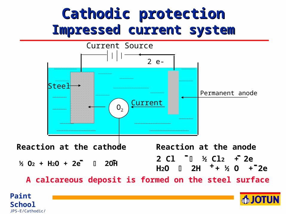
Cathodic protectionCathodic protectionImpressed current systemImpressed current system
A calcareous deposit is formed on the steel surface
Reaction at the cathode
½ O2 + H2O + 2e 2OH -- --
Reaction at the anode
2 Cl ½ Cl2 + 2eH2O 2H + ½ O + 2e
-- ----+

Paint SchoolJPS-E/Cathodic/23
Rapid corrosion
General corrosion
Some corrosion
100% Cathodic protection
Overprotection
Possible coating damage
Corrosion Potentials in SeawaterCorrosion Potentials in SeawaterZinc, Ag/Ag Cl and Cu/CuSOZinc, Ag/Ag Cl and Cu/CuSO4 R4 Reference Electrodeseference Electrodes
Increasing polarisation
Ag / Ag Cl Zinc
+ 0.50
- 0.25
+ 0.0
+ 0.25
- 0.55
- 1.30
-1.05
- 0.80
Potentials in volt
- 0.60
- 1.35
-1.10
- 0.85
Cu / CuSO4

Paint SchoolJPS-E/Cathodic/24
Full cathodic protection
(Steel surface passivated)
Free corrosion of steelCorrosion reduction , %
vs Zn 450 400 350 300 250 mV
vs Ag/AgC1 -600 -650 -700 -750 -800 mV
Reduction of corrosion rate of steel by Reduction of corrosion rate of steel by cathodic protection. Moving seawatercathodic protection. Moving seawater
Negative polarisation, mV
0
50
87,5
0 50 100 150 200Actual potential of the steel
Paint SchoolJPS-E/Cathodic/25
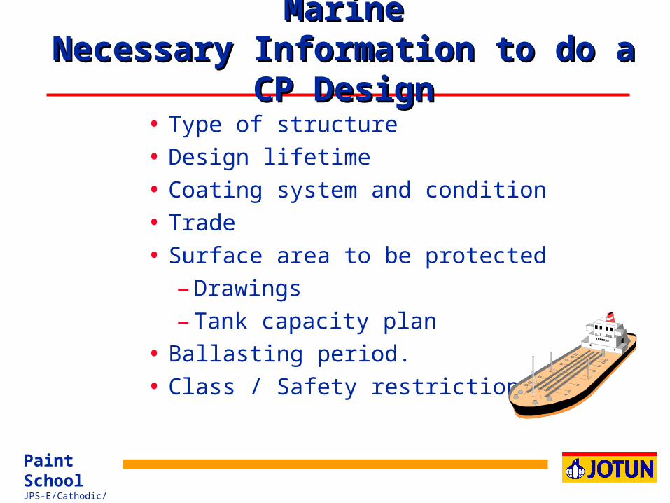
MarineMarineNecessary Information to do a CP DesignNecessary Information to do a CP Design
• Type of structure
• Design lifetime
• Coating system and condition
• Trade
• Surface area to be protected
– Drawings
– Tank capacity plan
• Ballasting period.
• Class / Safety restrictions

Paint SchoolJPS-E/Cathodic/26
MarineMarineDesign Criteria Design Criteria
• Design lifetime
• Coating system and condition
• Current density (Coating type and damages)
• Current distribution
• Electrolytic resistivity
• Environmental conditions / impacts
• Ballasting period.

Paint SchoolJPS-E/Cathodic/27
ProtectiveProtectiveDesign criteriaDesign criteria
• Type of structure
• Surface area to be protected
• Design lifetime
• Coating system and condition
• Protection potential
• Anode capacity
• Current distribution
• Electrolyte resistivity
• Environmental conditions / impacts
• Safety restrictions
Paint SchoolJPS-E/Cathodic/28
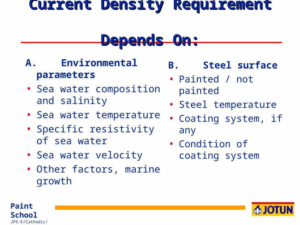
Current Density Requirement Current Density Requirement Depends On:Depends On:
A. Environmental parameters
• Sea water composition and salinity
• Sea water temperature
• Specific resistivity of sea water
• Sea water velocity
• Other factors, marine growth
B. Steel surface
• Painted / not painted
• Steel temperature
• Coating system, if any
• Condition of coating system

Paint SchoolJPS-E/Cathodic/29
Sacrificial Anode material selectionSacrificial Anode material selection
Main TypesMain Types
• Zinc
• Aluminium
• Magnesium
Anode material selectionAnode material selection
• Chemical composition
• Electrochemical performance
- Anode potential
- Stable current
- Consumption
• Anode corrosion pattern
• Price
• Class requirements

Paint SchoolJPS-E/Cathodic/30
Initial/final design current densities in A/m2
Tropical
(> 20 oC)
Sub-Tropical
(12-20 oC)
Temperate
(7 - 12 oC)
Arctic
(< 7 oC)
0.150
0.090
0.170
0.110
0.200
0.130
0.250
0.170
0.130
0.080
0.150
0.090
0.180
0.110
0.220
0.130
Depth
(m)
0 - 30
> 30
Current density requirement Current density requirement acc. to DNV RP B401 (1993)acc. to DNV RP B401 (1993)

Paint SchoolJPS-E/Cathodic/31
Me4an (average) design current densities in A/m 2
Depth
(m)
0 - 30
> 30
0.070 0.080 0.100 0.1201)
0.060 0.070 0.080 0.100
1) Effect of any ice scouring are not included
Current density requirement Current density requirement acc. to DNV RP B401 (1993)acc. to DNV RP B401 (1993)
Tropical
(> 20 oC)
Sub-Tropical
(12-20 oC)
Temperate
(7 - 12 oC)
Arctic
(< 7 oC)

Paint SchoolJPS-E/Cathodic/32
Coating CategoriesCoating CategoriesAcc. to DNV RP B401 (1993)Acc. to DNV RP B401 (1993)
Category I:Category I:
One layer of primer coat, about 50 microns nominal DFT (Dry Film Thickness)
Category II:Category II:
One layer of primer coat, plus minimum one layer of intermediate top coat, 150 to 250 microns nominal DFT.
Category III:Category III:
One layer of primer coat, plus minimum two layers of intermediate/top coats, minimum 300 microns nominal DFT
Category IV:Category IV:
One layer of primer coat, plus minimum three layers of intermediate top coats, minimum 450 microns nominal DFT.

Paint SchoolJPS-E/Cathodic/33
Coating Category
Depth(m)
I II III IV
k1 = 0.10k2
0 - 30 0.10 0.03 0.015 0.012> 30 0.05 0.02 0.012 0.012
k1 = 0.05k2
k1 = 0.02k2
k1 = 0.02k2
where fc = coating break down factor
t = coating lifetime
k1 and k2 = constants dependent on coating properties
fc = k1 + k2 t
Coating Break Down FactorCoating Break Down FactorAcc. to DNV RP B401 (1993)Acc. to DNV RP B401 (1993)

Paint SchoolJPS-E/Cathodic/34
ProtectiveProtectiveDesign Sacrificial Anode SystemDesign Sacrificial Anode System
A. Design criteria• Current density requirement
– initial
– mean
– final
• Design lifetime
• Anode material
B. Net anode weight requirementW= Exposed surface area (m²)
i = Mean current density (A/ m²)
C= Anode concumption rate (11.2 kg/year for Zn)
( 3.39 kg/year for Al)
L = Design lifetime
U = Utility factor (0.90, normally)
C. Initial and final current requirement
• I INITIAL = A * i init
• I FINAL = A * i final
D. Anode current system capacity
• Anode design (shape and size)
• Number of anodes

Paint SchoolJPS-E/Cathodic/35
Jotun Anode AlloysJotun Anode Alloys
Coral A
• Al-Zn-In Alloy
• Increased consumption rate by increasing temperature
Coral Z
• Zn alloy according to U.S. Mil. Spec. A-18001
• Intergranular corrosion above approximately 45 ºC
Noranode
• Zn-Al-Mg Alloy
• Environmental friendly
• Mil. Spec properties below 25 ºC
• Cost effective at elevated
temperature.– Reduced intergranular corrosion
– Current capacity and consumption
rate relatively stable at increasing
temperatures
– Recommended above 50 ºC

Paint SchoolJPS-E/Cathodic/36
Comparison of Cathodic Protection Systems Comparison of Cathodic Protection Systems General General AdvantagesAdvantages::
Sacrificial anode systems
• Simple, reliable and free from in-service operator surveillance
• System installation is simple
Impressed current systems
• Flexibility under widely varying operating conditions
• Weight advantage for large capacity, long life systems (reduced sea water drag)
• Low life cycle cost (LCC)• Low installation cost
for short term protection

Paint SchoolJPS-E/Cathodic/37
Comparison of Cathodic Protection SystemsComparison of Cathodic Protection Systems
General General DisadvantagesDisadvantages::
Sacrificial anode systems
• Large weight for large capacity, long life systems.
• Response to varying operating conditions is limited.
• Hydrodynamic loadings can be high (Seawater drag)
Impressed current systems
• Relative complexity of system demands high level of design expertise.
• In-service operator surveillance required.
• Vulnerable to component failure or loss of power.

Paint SchoolJPS-E/Cathodic/38
Why Choose an ICCP System on HullWhy Choose an ICCP System on Hull
• Smooth hull, no drag
• Flexible dry-docking intervals
• Low cost for long term operation
• Long lifetime, minimum of maintenance
• No welding required at dry docking
• No risk of damaging internal Paint systems
• Fully automatic corrosion protection

Paint SchoolJPS-E/Cathodic/39
Why Choose a SACP System on HullWhy Choose a SACP System on Hull
• Simple installation
• Maintenance free between dry docking
• Low cost for short term operation
• World-wide availability

Paint SchoolJPS-E/Cathodic/40
Lifecycle Cost of CP SystemsLifecycle Cost of CP Systems
13000 DWT Car Carrier13000 DWT Car Carrier
0
10,000
20,000
30,000
40,000
50,000
60,000
70,000
80,000
90,000
US
D
ICCP
Al
Zn
0 1 2 3 4 5 6 7 8 9 10 11 12 13 14 15 Years
Indicates Dry-docking Replacement of an ICCP component
Anodes and Reference electrodes can be replaced whilst in service.Normally, this is carried out at the dry-docking

Paint SchoolJPS-E/Cathodic/41
Life Cycle Cost of CP SystemsLife Cycle Cost of CP Systems
Panamax BulkcarrierPanamax Bulkcarrier
0
20,000
40,000
60,000
80,000
100,000
120,000
140,000
160,000
US
D
ICCP
Al
Zn
0 1 2 3 4 5 6 7 8 9 10 11 12 13 14 15 Years
Indicates Dry-docking Replacement of an ICCP component
Anodes and Reference electrodes can be replaced whilst in service.Normally, this is carried out at the dry-docking

Paint SchoolJPS-E/Cathodic/42
Cathodic Protection of Cathodic Protection of Ballast Water TanksBallast Water Tanks
1. Impressed current systems are not practical, and in most Classification Societies not permitted.
2. Magnesium anodes are not permitted.
3. In cargo, or adjacent tanks where the flash point is below 60 deg. C, Aluminium anodes are only permitted where the kinetic energy can not exceed 27,5 kpm (275 J).
4. There are no restrictions on the positioning of Zinc anodes.

Paint SchoolJPS-E/Cathodic/43
Tanks: Lloyd's register DNV
Segregated ballast 108 100 - 110
Dirty ballast 86 40 - 60
Washed cargo 108 80 - 90
Top wing 120 120
Coated (epoxy) 5 5 - 10
Soft Coats 20 - 40
Current density criteria mA/m 2
Current densityCurrent densityDesign CriteriaDesign Criteria
Paint SchoolJPS-E/Cathodic/44
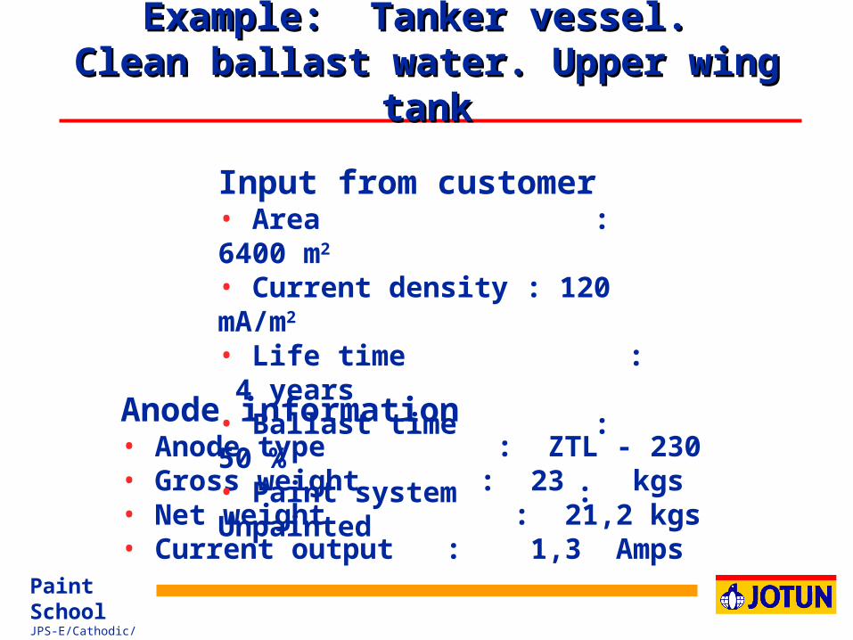
Example: Tanker vessel. Example: Tanker vessel. Clean ballast water. Upper wing Clean ballast water. Upper wing
tanktank
Anode information• Anode type : ZTL - 230• Gross weight : 23 kgs• Net weight : 21,2 kgs• Current output : 1,3 Amps
Input from customer• Area : 6400 m2 • Current density : 120 mA/m2
• Life time : 4 years• Ballast time : 50 %• Paint system : Unpainted

Paint SchoolJPS-E/Cathodic/45
TanksTanksConversion Factors from Volume to AreaConversion Factors from Volume to Area
C.T :
W.T :
Forepeak :
D.B.T :
U.W.T :
Volume * 0.7 - 0.9
Volume * 1.5 - 2.5
Volume * 1,5 - 2.5
Volume * 0.5 - 0.6
Volume * 1.5 - 2.5
= Area m²
= Area m²
= Area m²
= Area m²
= Area m²
Examples:Examples:
Deck head is includedExact calculations must be based on drawings

Paint SchoolJPS-E/Cathodic/46
Net weight:
6400 m2 x 120 mA/m2 x 4 yrs x 50% x 11,2 kg/A.yr ------------------------------------------------------ = 17203 kg 1000 100
17203 kg.No. of anodes: --------------- = 812 pcs : 812 pcs ZTL-230 21,2 kg/pc
Gross weight: 812 kg x 23kg/pcs = 18676 kg
Check of current requirement: 6400 m2 x 0,12 A/m2 = 768 Amp
Total current output : 1,3 Amp/pc x 812 pcs = 1055,6 Amp
Example: Tanker vessel. Example: Tanker vessel. Clean Ballast Water. Upper wing Clean Ballast Water. Upper wing
tanktank

Paint SchoolJPS-E/Cathodic/47
Information required:
• Theoretical calculation of net weight of anodes
– From previous calculation
• Number of small compartments
Design of Sacrificial Anode System Design of Sacrificial Anode System
Double Bottom and Other Narrow TanksDouble Bottom and Other Narrow Tanks

Paint SchoolJPS-E/Cathodic/48
Calculation:
Anode net weight:
Total net weight, kg = Net weight/pc
NOTE:NOTE: Usually, the number of compartments equal the number of pieces: Require one anode per compartment
Use nearest standard anode type
Design of Sacrificial Anode System Design of Sacrificial Anode System
Double Bottom and Other Narrow TanksDouble Bottom and Other Narrow Tanks
Number of compartments (pc)

Paint SchoolJPS-E/Cathodic/49
Example: Tanker vessel. Example: Tanker vessel. Clean ballast water. Double Bottom Clean ballast water. Double Bottom
TankTank
Anode information• Anode type : ZTL - 230• Gross weight : 23 kgs• Net weight : 21,2 kgs• Current output : 1,3 Amps
Input from customer• Area : 6400 m2 • Current density : 120 mA/m2
• Life time : 4 years• Ballast time : 50 %• Paint system : Unpainted

Paint SchoolJPS-E/Cathodic/50
Net weight:
6400 m2 x 120 mA/m2 x 4 yrs x 50% x 11,2 kg/A.yr ------------------------------------------------------ = 17203 kg 1000 100
17203 kg.No. of anodes: --------------- = 812 pcs : 812 pcs ZTL-230 21,2 kg/pc
Gross weight: 812 kg x 23kg/pcs = 18676 kg
Check of current requirement: 6400 m2 x 0,12 A/m2 = 768 Amp
Total current output : 1,3 Amp/pc x 812 pcs = 1055,6 Amp
Example: Tanker vessel. Example: Tanker vessel. Clean Ballast Water. Double Clean Ballast Water. Double
Bottom TankBottom Tank

Paint SchoolJPS-E/Cathodic/51
ICCP - Log report ReadingsICCP - Log report ReadingsCurrent Output Development With Current Output Development With
TimeTime
100 -
80 -
60 -
40 -
20 -
| | | | | | 1 2 3 4 5 6
System capacityAmp.
Years
1. d
ock
ing
2..
doc
kin
g
3. d
ock
ing
Grounding (Loss of coating)
ExampleExample

Paint SchoolJPS-E/Cathodic/52
Cathodic protection of tanksCathodic protection of tanksCurrent density at different coating breakdown ratioCurrent density at different coating breakdown ratio
Current density mA/m²
70
60
50
40
30
20
10
2
80
90
Tar Epoxy
Epoxy Mastic
Upper W
ing tank
0 5 10 20 30 40 50 60 70 80 90 100 110 120
100
Car
go/d
irty
bal
last
tank
s
Clean ball
ast t
anks f
ore-a
nd aft.
peak ta
nks
Cargo
/clea
n bal
last
tank
slower
win
g/dou
ble bot
tom
Soft coat / Flow coat
Coating breakdown

Paint SchoolJPS-E/Cathodic/53
Ship hull: Current Density at Ship hull: Current Density at Different Paint DamageDifferent Paint Damage
Current density, mA/ m²
Paint damage, %
100
45
15
0 20 70
Not applicable: Repaint
ICCP is recommended,not sacrificial anodes
Sacrificial Anodes and ICCP can be used

Paint SchoolJPS-E/Cathodic/54
*) Potential in seawater measured versus a copper/coppersulphate reference electrode
Galvanic Series in Sea WaterGalvanic Series in Sea WaterCorrosion Potentials vs. 3 Reference ElectrodesCorrosion Potentials vs. 3 Reference Electrodes
Graphite + 0.25 + 1.28 + 0.17Titanium 0 + 1.03 - 0.08Stainless steel (Passive) - 0.50 + 0.98 - 0.13Copper-Nickel (90/10) - 0.23 + 0.80 - 0.31Copper - 0.33 + 0.70 - 0.41Brass - 0.34 + 0.69 - 0.42Stainless steel (Corroding) - 0.35 + 0.68 - 0.43Mild steel - 0.66 + 0.37 - 0.69Aluminium - 0.80 + 0.23 - 0.88Zinc - 1.03 0 - 1.11Magnesium - 1.60 - 0.57 - 1.68
Metal / Alloy Ag / AgCl Zn Cu/Cu SO4

Paint SchoolJPS-E/Cathodic/55
Corrosion Secondary structure
Pipeline
Anode+_
InterferenceInterference

Paint SchoolJPS-E/Cathodic/56
2
TypeAnode current density
in seawater(A/m )
Consumption rate(kg/A year)
500 - 1000 < 1 x 10
500 - 1000 1000 - 5000
6 x 10 1 x 10
160 - 220 160 - 220
0,05 - 0,2 0,03 - 0,06
10 - 40 0,2 - 0,5
10 - 40 0,2 - 0,5
- 7 - 9
-6
-6
-5
2
MIXED METALOXYDE
PLATINIUM- Disc- Thread
LEAD-SILVERPb - 6% Sb - 1% AgPb - 6% Sb - 1% Ag
GRAPHITE
IRON-SILISIUMFe - 14,5% Si - 4,5% Cr
SCRAP IRON
Impressed current system anodesImpressed current system anodes

Paint SchoolJPS-E/Cathodic/57
Anode performance dataAnode performance data
Anode Specific Closed circuit Driving Capacity Consumption types gravity potential vs. Zn voltage (Ah/Kg) rate (Kg/dm ) ( Volt) (Volt) ( Kg/ A*Year)3
Zinc
Aluminium
Magnesium
7.13 0 0.23 781 11.2
2.78 -0.02 0.25 2585 3.39
1.84 -0.47 0.7 1200 7.3

Paint SchoolJPS-E/Cathodic/58
Aluminium AnodesAluminium AnodesSmall vesselsSmall vessels
This guide is based on a 3 year (36 month) replacement period (dry-docking interval).
Vessel Type Surface Anode Type Current Density - mA/m2 Number of Total Area (% coating breakdown) Anodes Weight
Kgs
Tug / Small Vessels 500 A - 50 25 (15 %) 32 160
Supply Vessel 2000 A - 80 20 (10 - 15 %) 60 480
Reefer / Container 4000 A -130 15 (5 - 10 %) 58 754
Tanker / Bulker 18000 A - 180 10 (2-5 %) 120 2160
This design is for the hull only and does not allow for the seachests, thruster tunnels etc..
The calculation is the same, but with specific current densities.

Paint SchoolJPS-E/Cathodic/59
This guide is based on a 3 year (36 month) replacement period (dry-docking interval).
Vessel Type Surface Area
Anode Type Current Density Number of pieces
Total- mA/m2 Gross
(% coating breakdown) Weight - Kgs
Tug / Small Vessels 500 Z-85 25 (15 %) 54 459
Supply Vessel 2000 Z-160 20 (10 - 15 %) 92 1472
Reefer / Container 4000 Z-270 15 (5 - 10 %) 80 2160
Tanker / Bulker 18000 Z-200 10 (2-5 %) 316 6320
This design is for the hull only and does not allow for the seachests, thruster tunnels etc.. The calculation is the same, but with specific current Densities
Zinc AnodesZinc Anodes

Paint SchoolJPS-E/Cathodic/60
Principle : Effect of using CP Principle : Effect of using CP
Corrosion Curves depend on - Coating condition - CP-design
Coating breakdown
CP installed
CP and coating at newbuilding
Time
Corrosion

Paint SchoolJPS-E/Cathodic/61
Steel passivation by sacrificial anodesSteel passivation by sacrificial anodes
Paint
Steel
Rust
Without Cathodic Protection
Paint
Steel
With Cathodic ProtectionAnodeAnode current
Seawater
Seawater
Calcareous layer

Paint SchoolJPS-E/Cathodic/62
Ships hull: Current density as Ships hull: Current density as function of coating breakdownfunction of coating breakdown
Coating breakdown Current density
2 - 5 % 10 mA/m2
5-10 % 15 mA/m2
10-15 % 20 mA/m2
15-20 % 30 mA/m2
20-25 % 40 mA/m2
25-30 % 50 mA/m2

Paint SchoolJPS-E/Cathodic/63
Location Current density
SeachestsThruster tunnelPropeller nozzleRudderRudder flapsAnti-suction tunnelsPropeller (Uncoated) Azimuth propeller
40 mA/m2
150 mA/m2
150 mA/m2
100 mA/m2
150 mA/m2
100 mA/m2
500 mA/m2
150 mA/m2
CP of ships:CP of ships:Additional Areas Requiring Protection.Additional Areas Requiring Protection.

Paint SchoolJPS-E/Cathodic/64
Sacrificial Anode SystemSacrificial Anode System
Aluminium alloy anodes Zinc alloy anodes (technically equal)
Aluminium is recommended prior Aluminium is recommended prior to zinc because:to zinc because:
Aluminium anode weight is approx. 1/3 of zinc Total price for equal protection: Al. anodes
approx 1/2 of Zinc anodes Lower installation costs due to weight difference

Paint SchoolJPS-E/Cathodic/65
Cathodic ProtectionCathodic Protection
ICCP - Impressed Current SACP - Sacrificial Anodes EAF - Electrolytic Antifouling System for
seawater systems (CUPROBAN) Slip ring arrangement for propeller shaft
Coatings and Cathodic ProtectionCoatings and Cathodic Protection
The Single Source SolutionThe Single Source Solution
Paint SchoolJPS-E/Cathodic/66
Sacrificial Anode System Sacrificial Anode System DisadvantagesDisadvantages
Increases the frictional resistanceAdds weight to the vesselThe shipyard often supply the anodes at a
very low price (charge more for installation)

Paint SchoolJPS-E/Cathodic/67
Cathodic protectionCathodic protection
Sacrificial Anodes or Impressed CurrentSacrificial Anodes or Impressed Current
Anodes increase the frictional resistance compared with impressed current systems
Adds weight to the vessel Aluminium anode weight is approx. 1/3 of zinc Total price for equal protection:
Al. anodes approximately half the price of Zinc anodes

Paint SchoolJPS-E/Cathodic/68
Location of Pitguard AnodesLocation of Pitguard Anodes
Web Frame
Web Frame

Paint SchoolJPS-E/Cathodic/69
Type of products Type of products Grounding EquipmentGrounding Equipment
• Rudder grounding
• Shaft grounding equipment
• Earthing cables

Paint SchoolJPS-E/Cathodic/70
Slipring ArrangementSlipring Arrangement
Shaft
Silver Graphite Brush
Steel Slipring
Earth to Hull
mV meter
Silver Inlay

Paint SchoolJPS-E/Cathodic/71
Slip Ring ArrangementSlip Ring Arrangement
• Protects against spark corrosion in the engine bearings– Very high cost to replace bearing
– The vessel cannot operate with damaged bearings
• Reduces corrosion on propeller– Extends propeller life
– Reduces polishing needs on the propeller
Paint SchoolJPS-E/Cathodic/72
Slip Ring ArrangementSlip Ring Arrangement
Grounding of the propeller and shaftFixed to intermediate shaft in engine roomBeneficial if SACP or ICCP systems are
used

Paint SchoolJPS-E/Cathodic/73
• Thank You !


![cathodic protection in practise · 2 [CATHODIC PROTECTION/BM] CATHODIC PROTECTION P E FRANCIS 1 INTRODUCTION The first practical use of cathodic protection is generally credited to](https://img.pdfslide.us/doc/110x75/5ace93c87f8b9ae2138b87e4/cathodic-protection-in-cathodic-protectionbm-cathodic-protection-p-e-francis.jpg)