Embed Size (px)
Citation preview

One Company … Unlimited Solutions
Training Solutions
1
ACS800 Liquid Cooling Unit

One Company … Unlimited Solutions
Training Solutions
2
Objectives
Describe the connections of the cooling unit
Describe the functionality of the RMIO board
Locate the components of the cooling unit
Describe the use of the control panel for local controls and read actual values and alarms
Upon the completion of this module,you will be able to

One Company … Unlimited Solutions
Training Solutions
3
Liquid Cooling Unit
D
One Company … Unlimited Solutions
Training Solutions
4
Dimensions
There are two LCU cabinet sizes The 300 mm wide, 70 kW cooling
power with single pump, about 100 l/min depending on the system pressure.
The 600 mm wide, 195 kW cooling power with redundant pumps, about 300 l/min depending on the system pressure.
600mm
(630mm as separate unit)
600mm
2000mm
195kW unit

One Company … Unlimited Solutions
Training Solutions
5
PI-diagram of the 195kW unit
GA-102 GA-101
PIA202
PIA203
PI204
TIA201
External coolingreturn
Input fromExternal cooling
Internal coolingreturn from cabinets
Internal coolingto cabinets
V307V306
EA-100
PA-102
V301
V302
V303
V304 V305
V308
V309
V310
V311
V312 V313
V314
V315V316
Expansion tank
Pump

One Company … Unlimited Solutions
Training Solutions
6
Internal Cooling System Diagram
Air-to-Coolant Heat
Exchanger
A-to-C-
Heat Exch.
Air-to-Coolant Heat
Exchanger
Air-to-Coolant Heat
Exchanger
Air-to-Coolant Heat
Exchanger
A-to-C-
Heat Exch.
A-to-C-
Heat Exch.
Inlet and outlet valves
(a and b)
Drain and bleed valves
(c and d)

One Company … Unlimited Solutions
Training Solutions
7
Component Layout
Internal liquidconnection
Expansion tank
Internal liquidconnection
Motor protective circuit breakers
External liquidconnection
RDCU
Heat exchanger
Base pan which is able tohold 4 to 6 liters of liquid
Bleed valve
Pressure gauge
Drain / filling valve
Pump

One Company … Unlimited Solutions
Training Solutions
8
Pumps
In a two-pump system, the selection of automatic alternation of the pumps is recommended
prevents drying out and ensures a longer life of the pumps
The pumps are prefilled with a water-glycol-inhibitor mixture
Without liquid the pump must not be rotated at all

One Company … Unlimited Solutions
Training Solutions
9
Specifications
GRUNDFOS CRN 10-2 A-P-G-E-HQQE
Flow, Q: 10 m3/h
Head, H: 97 m max 117 m
Liquid temp.: –40 C to +180 C
Operation pres.: 16 bar / 120 C
Rotation direction: CCW
Motor: 50 Hz 60 Hz3 kW 4 hp380 - 415 V, D
660 - 690 V, Y
380 - 480 V, D
660 - 690 V, Y2900 – 2920 rpm
3470 – 3520 rpm

One Company … Unlimited Solutions
Training Solutions
10
Temperature Sensor
Type: PT100
Installed in AISI316 sensor pocket
¼” thread

One Company … Unlimited Solutions
Training Solutions
11
Pressure Sensor Sensor: Thick film on
ceramic
Measuring Range: 0...10 bar
Output/ Supply Voltage:4...20 mA/24 (9...30) VDC
Operating Temperature:Usupply = 24 VDC: -25 ...+85 C
Media Temperature ≤ 60 bar: -25 ...+85 C
Torque Moment Pressure Connection: 15...20Nm
PI
+
-
┴
Us positive supply
Us Negative supply
Earth

One Company … Unlimited Solutions
Training Solutions
12
Liquid Leakage Detector
Type: VVA 1
Installation in collecting trays
Protection class IP54

One Company … Unlimited Solutions
Training Solutions
13
Pressure Levels
Base pressure
recommended base pressure is from 100 to 150 kPa
maximum base pressure is 200 kPa
Operating pressure
base pressure + pressure created by the pump
maximum operating pressure is 600 kPa
Pressure gauge PI 204 monitors the system pressure
Base pressure of the expansion tank should be 40kPa

One Company … Unlimited Solutions
Training Solutions
14
Temperature Levels
Internal cooling system: Minimum inlet temperature: 5 C (41 F)
Maximum inlet temperature: 42 C (107 F)
Maximum temperature variation: 4 C ( 7 F)
Maximum temperature rise: 13 C (23 F); depends on mass flow.
External cooling system: Minimum inlet temperature: 5 C (41 F)
Maximum inlet temperature: 38 C (100 F)
Delta T max. 11 C (52 F)
Maximum temperature variation: 7 C ( 45 F)

One Company … Unlimited Solutions
Training Solutions
15
Temperature Control
ACS800-1007LC 195 kW
EA-100
V311Closed
V313
V312Fully Open
TIA201
V310
External coolingreturn
Input fromExternal cooling
TC
RDCU
RAIO
ACS800-1007LC cabinet
Temperature0 (4)…20 mA

One Company … Unlimited Solutions
Training Solutions
16
RMIO Board ConnectionsTerminal Block X21 RMIO board
1 VREF Reference voltage +10 V DC max. 10 mA
2 GND
3 AI1+ Analogue Input 1
Temperature TIA-201 0...10 V4 AI1-
5 AI2+ Analogue Input 2
Pressure PIA-202 (0)4 ... 20mA 6 AI2-
7 AI3+ Analogue Input 3
Pressure PIA-203 (0)4 ... 20mA 8 AI3-
9 AO1+ Analogue Output 1
Current source for TIA-201 0 ... 20 mA 10 AO1-
11 AO2+ Analogue Output 2
0 … 20 mA12 AO2+
Terminal Block X22
1 DI1 Pump 1 MCB
2 DI2 Pump 2 MCB
3 DI3 Leakage Detector
4 DI4 Fan Control Relay
5 DI5 Line Up Stand By
6 DI6 Start / Stop
7 +24 VDC + 24 VDC max. 100 mA
8 +24 VDC
9 DGND1 Digital ground
+ 24 VDC max. 100 mA10 DGND2
11 DI7 (DI IL) Reset
Terminal Block X23
1 +24 VDC Aux. voltage output 24 VDC, 250 mA or 130 mA if NLMD-01 option included2 GND
Terminal Block X25
1 RO11 Relay output 1
Pump 12 RO12
3 RO13
Terminal Block X26
1 RO21 Relay output 2
Pump 22 RO22
3 RO23
Terminal Block X26
1 RO31 Relay output 3
LCU Fault2 RO32
3 RO33
K1
N
L
K2
To cooledunits
F10
F1F2
VVA1K3
TIA-201
PIA-202
PIA-203
21
21

One Company … Unlimited Solutions
Training Solutions
17
Instrument Diagram
One Company … Unlimited Solutions
Training Solutions
18
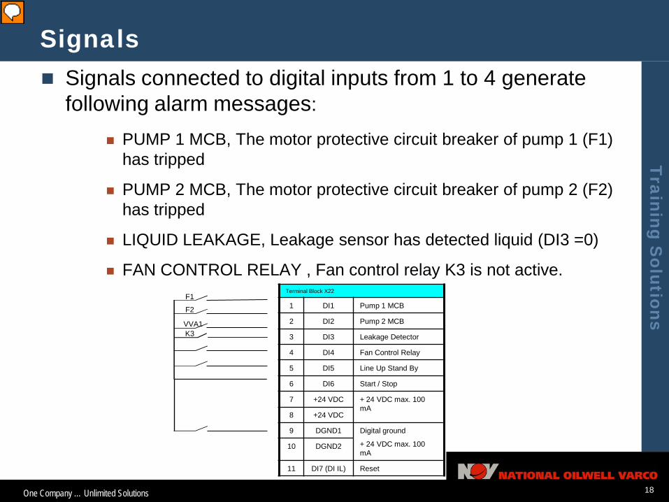
Signals Signals connected to digital inputs from 1 to 4 generate
following alarm messages:
PUMP 1 MCB, The motor protective circuit breaker of pump 1 (F1) has tripped
PUMP 2 MCB, The motor protective circuit breaker of pump 2 (F2) has tripped
LIQUID LEAKAGE, Leakage sensor has detected liquid (DI3 =0)
FAN CONTROL RELAY , Fan control relay K3 is not active.Terminal Block X22
1 DI1 Pump 1 MCB
2 DI2 Pump 2 MCB
3 DI3 Leakage Detector
4 DI4 Fan Control Relay
5 DI5 Line Up Stand By
6 DI6 Start / Stop
7 +24 VDC + 24 VDC max. 100 mA
8 +24 VDC
9 DGND1 Digital ground
+ 24 VDC max. 100 mA
10 DGND2
11 DI7 (DI IL) Reset
F1
F2
VVA1K3

One Company … Unlimited Solutions
Training Solutions
19
Outputs
Relay output 1 is used to start / stop pump 1
Relay output 2 is used to start / stop pump 2
If the parameter 33.01 CONTROL TYPE is set to Local, relay output 3 is used for fault indication to cooled units

One Company … Unlimited Solutions
Training Solutions
20
LCU Control Places
An overriding system can control ACS800-1007LC.
ACS800-1007LC is connected to other systems in the same way as drive units
See the drive or inverter unit hardware manual of your delivery
ACS800-1007LC can also be controlled locally via its digital inputs
Service controls via Control Panel (CDP 312R)

One Company … Unlimited Solutions
Training Solutions
21
LCU Control Functions This table lists how some control functions are performed
Function is performed viaControl place selection (i.e. whether the ACS800-1007LC is controlled by an overriding system, via Control Panel or digital inputs)
Parameter 33.01 CONTROL TYPE
Parameter setting (including warning and trip limits)
The control panel or PC-Tool
Monitoring fault and warning messages, state information and measured signals
The control panel and an overriding system
Communication with an overriding system
Parameter 7.01 CONTROL WORD
Control of the ACS800-1007LC without an overriding system
Digital output RO3 and digital inputs DI5 and DI6. RO3 indicates a fault, DI5 indicates that the system is ready for start (when Par. 33.03 STAND-BY USE is set to YES), DI6 starts/stops the LCU.