Embed Size (px)
Citation preview

1
Vacuum chambers for LHC LSS
TS Workshop 2004
Pedro Costa Pinto
TS department, MME groupSurface Characterization & Coatings Section

2
the Long Straight Sections of the LHC
The LHC Long Straight Sections (LSS), operating at room temperature, are interposed between the cryogenic modules of the LHC.
The NEG materials, developed at CERN, will assure the main pumping of the LSS vacuum system.
NEG films were chosen for their benefical characteristics: high distributed pumping speed, low static and dynamic degassing and low secondary electron yield.
3
Heating in vacuum Oxide dissolution -> activation
T = RT
T = Ta
T = RT
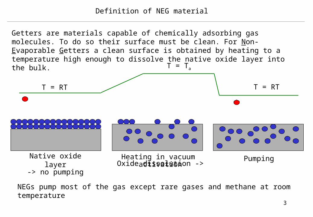
NEGs pump most of the gas except rare gases and methane at room temperature
Native oxide layer-> no pumping
Pumping
Getters are materials capable of chemically adsorbing gas molecules. To do so their surface must be clean. For Non-Evaporable Getters a clean surface is obtained by heating to a temperature high enough to dissolve the native oxide layer into the bulk.
Definition of NEG material
4
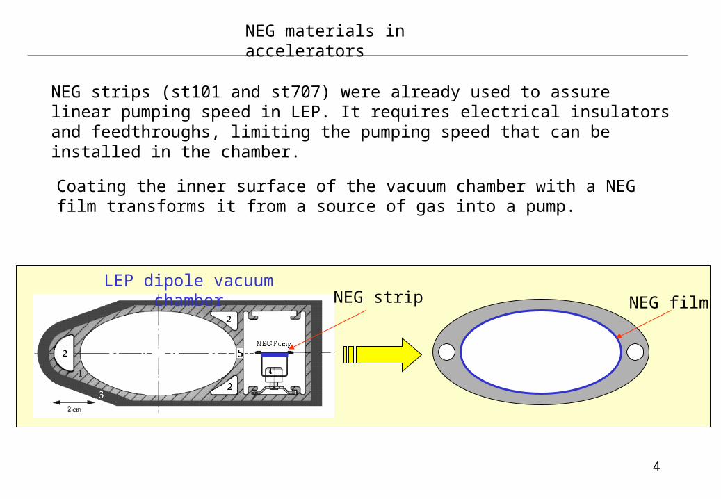
NEG materials in accelerators
NEG film
NEG strips (st101 and st707) were already used to assure linear pumping speed in LEP. It requires electrical insulators and feedthroughs, limiting the pumping speed that can be installed in the chamber.
Coating the inner surface of the vacuum chamber with a NEG film transforms it from a source of gas into a pump.
LEP dipole vacuum chamber NEG strip

5
Ti
ZrV
Intertwisted Ti, Zr, and V elemental wires give rise to Ti30 -Zr30 -V40 film composition
The best NEG for the LHC: TiZrV
To be compatible with the structural materials of the vacuum chambers, NEG film should allow a complete dissolution of the oxide layer at a reasonable low temperature.
The lowest activation temperature was found in a wide range of composition in the Ti-Zr-V system: 180 °C (24 h heating).
Typical thickness about 1m.
6
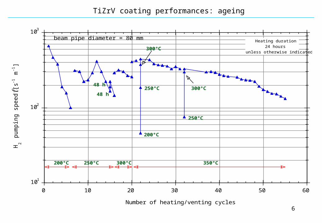
TiZrV coating performances: ageing
101
102
103
0 10 20 30 40 50 60
H2 p
um
pin
g s
pe
ed
[ s-1
m-1
]
Number of heating/venting cycles
200°C 250°C 300°C 350°C
200°C
250°C
300°C
48 h
48 h
250°C
300°C
Heating duration 24 hours
unless otherwise indicated
beam pipe diameter = 80 mm

7
675 LSS drift space chambers: Ø 80 mm, L=0.3m ~ 7m (work-package of the EST division)
NEG film coatings in the LHC
About 285 non-standard LSS chambers for the warm magnets
About 50 chambers for the experimental areas.

8
NEG film coating applications in the LHC
The two stainless steel flanges are each vacuum brazed to OFE Cu stubs
Welding of the flanges/Cu stubes assembly to the OFS Cu tube
Leak test
Surface treatment: degreasing, etching 70m and passivation of the surface
NEG coating by DC magnetron sputtering
Overview of the fabrication of the LSS drift space chambers:
MME-AS (bldg 112)MME-AS (bldg 927)Contract 3040 (bldg 927)MME-CEM (bldg 118)MME-SC (bldg 181)

9
Building 181
The NEG coating facilities
assembling bench
3 coating units
Storage system (under N2 atmosphere)
monitoring
karts with chambers

10
manyfold
chambers
extentions
Bellows
Cathode’s feedthrough
UHV valves
SolenoidL=8m
=60cm
To UHV pumpingstation
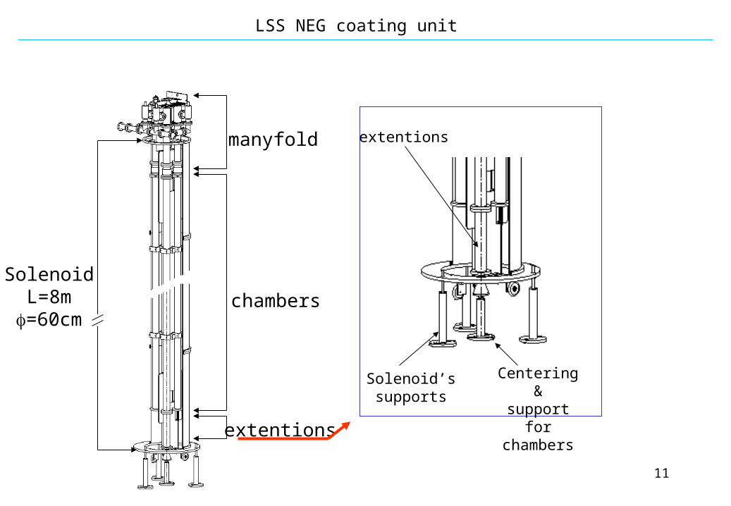
LSS NEG coating unit
11
LSS NEG coating unit
SolenoidL=8m
=60cm
manyfold
chambers
extentions
extentions
Solenoid’ssupports
Centering &
support forchambers

12
LSS NEG coating production: the coating parameters
Discharge gas -> Kr
Current I -> 1.5 A
Potential U -> -500 V
Pressure -> 4x10⁻³ Torr
Magnetic field -> 150 G
Supply atoms for the ionization process.
Defines the energy of the ions.
Increase the ionization efficiency improving stability and allowing lower discharge pressure
Defines the rate of the ions hitting the cathode.
Noble gas. Kr chosen in order to minimize the discharge gas trapping on the coating.
Deposition rate -> 0.2 m/h =>10h for a 2m coating

13
LSS NEG coating production timing
System 1 System 2time
8:30Leak test
Start coating
Leak test
Demount the 4 chambers coated
the day before
Pump it with storage vacuum
system12:30
Inject N2 and pinch-off
Mount cradle with four uncoated
chambers
Start pumpingStop coating
9:30
10:30
11:30
13:30
14:30
15:30
16:30
18:30
17:30
PRODUCTION RATE: 20 CHAMBERS/WEEK

14
After coating:
During coating:
Before coating: Visual inspection of the internal surface of each chamber;
Monitoring of the discharge parameters (I,V,P);
25 cm long chambers for pumping speed measurements (1 per batch of 4)
Leak detection: mass spectra before and after coating and monitoring mass 20 to detect an eventual leak during the coating process.
Visual inspection of the coating
Whitness samples:
15x15mm2 to measure coating thickness by SEM, composition by EDX and activation by AES.
The quality assessment
Every month one chamber is fully characterized (pumping speed, surface capacity, CH4 and Kr outgassing)
15
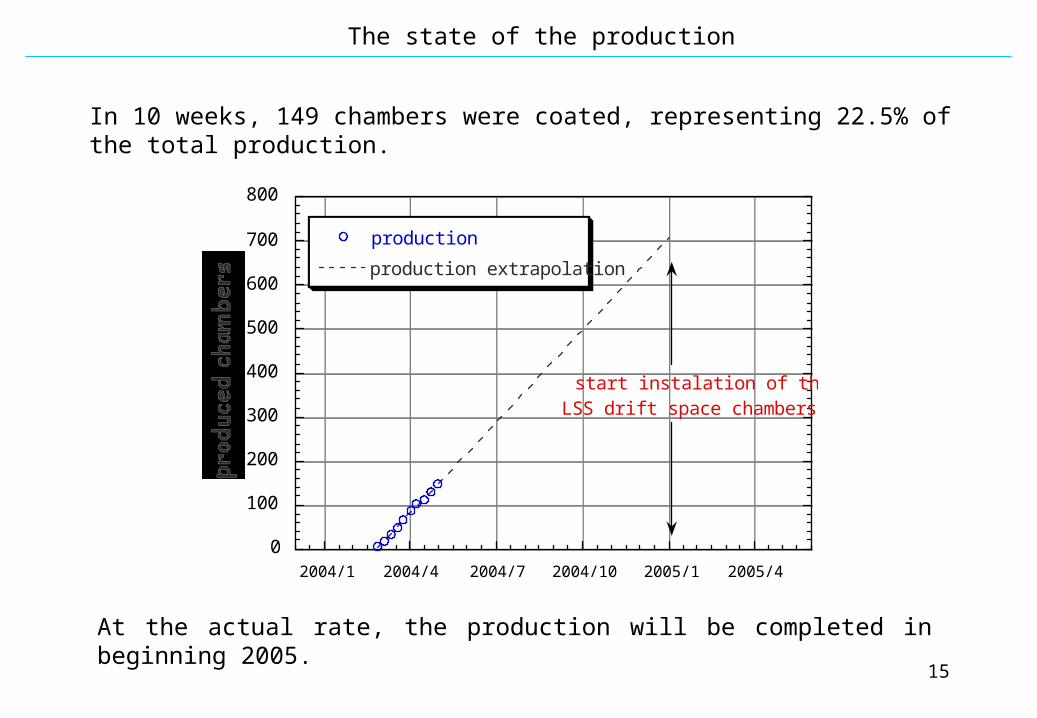
The state of the production
0
100
200
300
400
500
600
700
800
2004/1 2004/4 2004/7 2004/10 2005/1 2005/4
production
production extrapolation
start instalation of the LSS drift space chambers
In 10 weeks, 149 chambers were coated, representing 22.5% of the total production.
At the actual rate, the production will be completed in beginning 2005.
![一般社団法人 電波産業会 - 3GPP TS 23...[20] 3GPP TS 23.041: "Technical realization of Cell Broadcast Service (CBS)". [21] 3GPP TS 29.280: "3GPP Sv interface (MME to MSC,](https://img.pdfslide.us/doc/110x75/60f3201794f5be375d7249c9/ec-ec-3gpp-ts-23-20-3gpp-ts-23041-technical.jpg)