Embed Size (px)
Citation preview

1© Unitec New Zealand
DE4401&APTE 5601 Topic 3
DC CIRCUITSKIRCHHOFF’S LAWS
VOLTAGE AND CURRENT DIVIDERS

2© Unitec New Zealand
In this presentation:
• Introducing:– Kirchhoff’s Voltage Law – Kirchhoff’s Current Law– Voltage Divider– Current Divider

Parallel and series circuits: limitations
• Some problems are easily solved by calculating total parallel or series resistance, but there are many more that cannot be solved that easily.
3© Unitec New Zealand
Voltage in series circuit
4© Unitec New Zealand
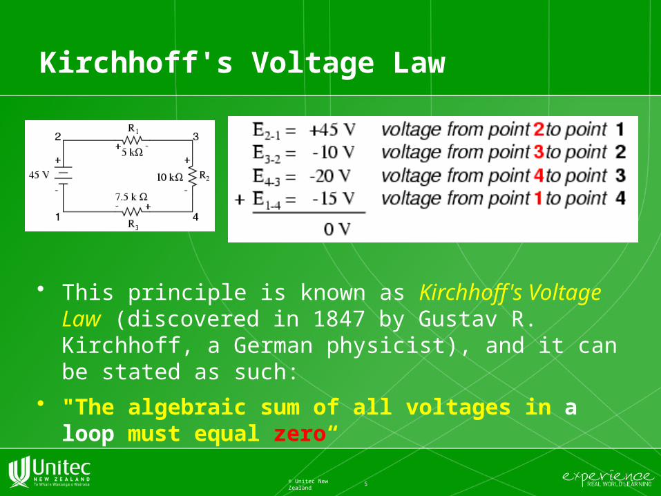
Kirchhoff's Voltage Law
• This principle is known as Kirchhoff's Voltage Law (discovered in 1847 by Gustav R. Kirchhoff, a German physicist), and it can be stated as such:
• "The algebraic sum of all voltages in a loop must equal zero“
5© Unitec New Zealand

Loop
• Starting at any point in the loop continue in the same direction noting the direction of all the voltage drops, either positive or negative, until you get back to the starting point. It is important to maintain the same direction either clockwise or anti-clockwise or the final voltage sum will not be equal to zero.
6© Unitec New Zealand

Branch, Nodes and Loop
• KVL can be used to determine an unknown voltage in a complex circuit, where all other voltages around a particular "loop" are known.
7© Unitec New Zealand
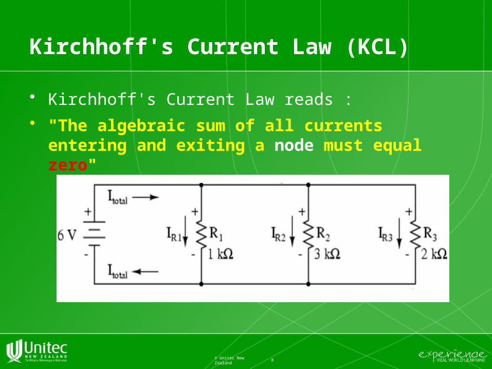
Kirchhoff's Current Law (KCL)
• Kirchhoff's Current Law reads :
• "The algebraic sum of all currents entering and exiting a node must equal zero"
8© Unitec New Zealand

Node
• The term Node in an electrical circuit generally refers to a connection or junction of two or more current carrying paths or elements such as cables and components. Also for current to flow either in or out of a node a closed circuit path must exist.
9© Unitec New Zealand
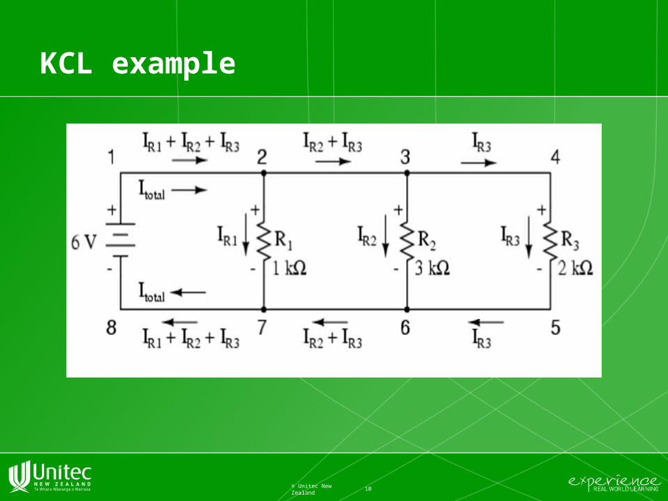
KCL example
10© Unitec New Zealand

Application of KVL and KCL
• Find the current flowing in the 40Ω Resistor, R3
11© Unitec New Zealand
Voltage divider circuits
12© Unitec New Zealand
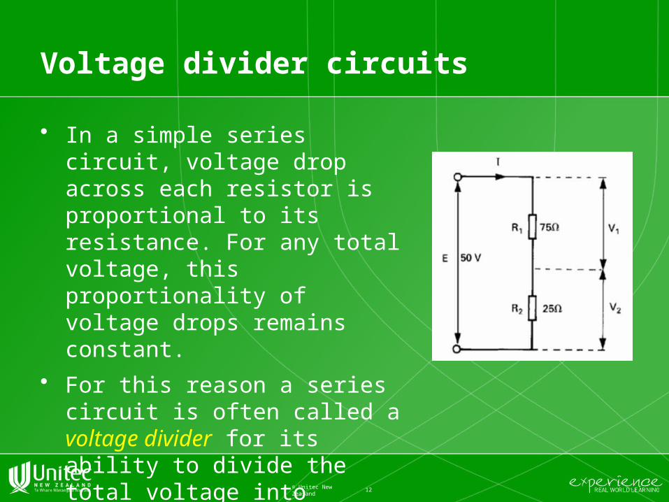
• In a simple series circuit, voltage drop across each resistor is proportional to its resistance. For any total voltage, this proportionality of voltage drops remains constant.
• For this reason a series circuit is often called a voltage divider for its ability to divide the total voltage into fractional portions of constant ratio.

Voltage divider formula
13© Unitec New Zealand
• The ratio of individual resistance to total resistance is the same as the ratio of individual voltage drop to total supply voltage in a voltage divider circuit. This is known as the voltage divider formula

Voltage Divider General Formula
• The Voltage across any resistor in a chain of resistors in series across a Voltage Source can be found from the ratio of that resistance to the Total resistance
14© Unitec New Zealand

Current divider circuits
15© Unitec New Zealand
It is sometimes necessary to find the individual branch currents in a parallel circuit if the resistances and total current are known, but the voltage across the resistance bank is not known. When only two branches are involved, the current in one branch will be some fraction of the total current. This fraction is the quotient of the second resistance divided by the sum of the resistances.


![Oriental Motor RBK Series Stepping Motors Component V oltage V p-p [V] Vibration Component V oltage V p-p [V] Third Harmonic Waveform Correction Function Vibration Suppression Function](https://img.pdfslide.us/doc/110x75/5aa511437f8b9a1d728cad0e/oriental-motor-rbk-series-stepping-motors-component-v-oltage-v-p-p-v-vibration.jpg)