Embed Size (px)
Citation preview
1
UNIT–03
UNIT-03/LECTURE-01
Telephone Network (RGPV dec 2011)
A telephone network is a telecommunications network used for telephone calls between two
or more parties.
There are a number of different types of telephone network:
A fixed line network where the telephones must be directly wired into a single
telephone exchange. This is known as the public switched telephone network or PSTN.
A wireless network where the telephones are mobile and can move around anywhere
within the coverage area.
A private network where a closed group of telephones are connected primarily to
each other and use a gateway to reach the outside world. This is usually used inside
companies and call centres and is called a private branch exchange (PBX).
Public telephone operators (PTOs) own and build networks of the first two types and provide
services to the public under license from the national government. Virtual Network Operators
(VNOs) lease capacity wholesale from the PTOs and sell on telephony service to the public
directly.
Network Topology
Network topology is the arrangement of the various elements (links, nodes, etc.) of a
computer network. Essentially, it is the topological structure of a network, and may be
depicted physically or logically. Physical topology refers to the placement of the
network's various components, including device location and cable installation, while
logical topology shows how data flows within a network, regardless of its physical
design. Distances between nodes, physical interconnections, transmission rates,
and/or signal types may differ between two networks, yet their topologies may be
identical.
A good example is a local area network (LAN): Any given node in the LAN has one or
more physical links to other devices in the network; graphically mapping these links
results in a geometric shape that can be used to describe the physical topology of the
network. Conversely, mapping the data flow between the components determines
the logical topology of the network.
we dont take any liability for the notes correctness. http://www.rgpvonline.com
2
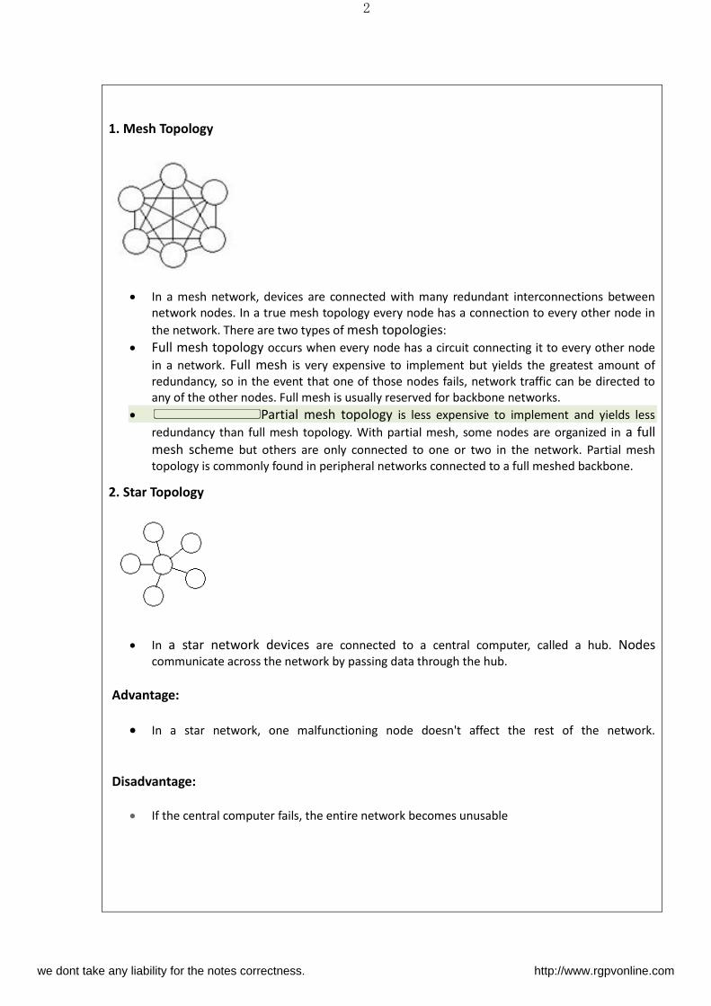
1. Mesh Topology
In a mesh network, devices are connected with many redundant interconnections between
network nodes. In a true mesh topology every node has a connection to every other node in
the network. There are two types of mesh topologies:
Full mesh topology occurs when every node has a circuit connecting it to every other node
in a network. Full mesh is very expensive to implement but yields the greatest amount of
redundancy, so in the event that one of those nodes fails, network traffic can be directed to
any of the other nodes. Full mesh is usually reserved for backbone networks.
Partial mesh topology is less expensive to implement and yields less
redundancy than full mesh topology. With partial mesh, some nodes are organized in a full
mesh scheme but others are only connected to one or two in the network. Partial mesh
topology is commonly found in peripheral networks connected to a full meshed backbone.
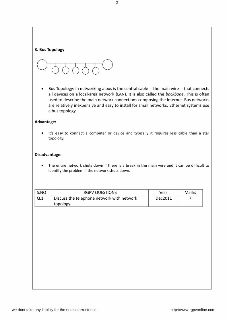
2. Star Topology
In a star network devices are connected to a central computer, called a hub. Nodes
communicate across the network by passing data through the hub.
Advantage:
In a star network, one malfunctioning node doesn't affect the rest of the network.
Disadvantage:
If the central computer fails, the entire network becomes unusable
we dont take any liability for the notes correctness. http://www.rgpvonline.com
3
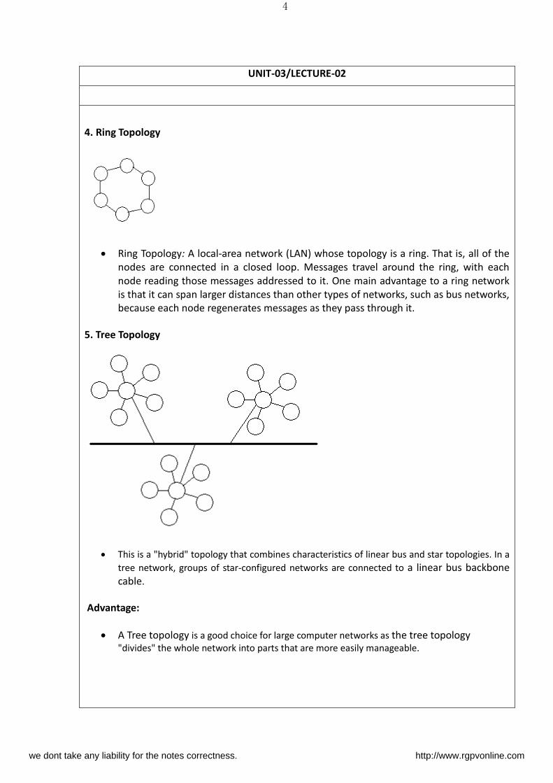
3. Bus Topology
Bus Topology: In networking a bus is the central cable -- the main wire -- that connects
all devices on a local-area network (LAN). It is also called the backbone. This is often
used to describe the main network connections composing the Internet. Bus networks
are relatively inexpensive and easy to install for small networks. Ethernet systems use
a bus topology.
Advantage:
It's easy to connect a computer or device and typically it requires less cable than a star
topology.
Disadvantage:
The entire network shuts down if there is a break in the main wire and it can be difficult to
identify the problem if the network shuts down.
S.NO RGPV QUESTIONS Year Marks
Q.1 Discuss the telephone network with network
topology.
Dec2011 7
we dont take any liability for the notes correctness. http://www.rgpvonline.com
4
UNIT-03/LECTURE-02
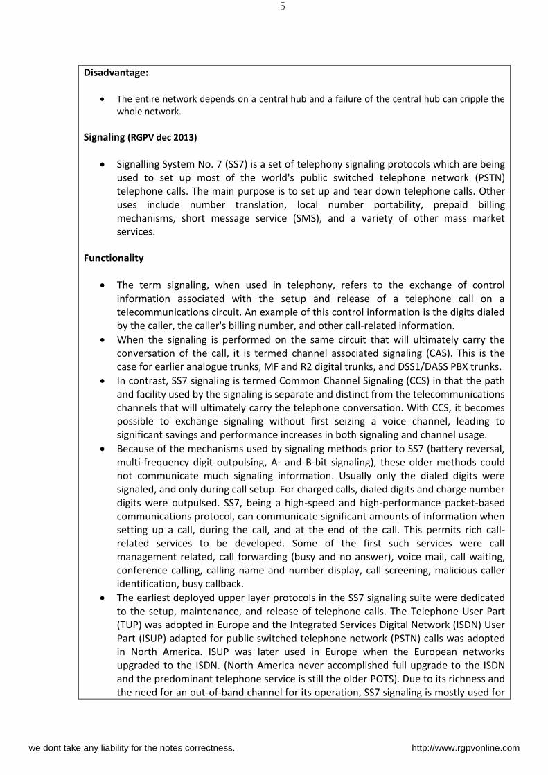
4. Ring Topology
Ring Topology: A local-area network (LAN) whose topology is a ring. That is, all of the
nodes are connected in a closed loop. Messages travel around the ring, with each
node reading those messages addressed to it. One main advantage to a ring network
is that it can span larger distances than other types of networks, such as bus networks,
because each node regenerates messages as they pass through it.
5. Tree Topology
This is a "hybrid" topology that combines characteristics of linear bus and star topologies. In a
tree network, groups of star-configured networks are connected to a linear bus backbone
cable.
Advantage:
A Tree topology is a good choice for large computer networks as the tree topology
"divides" the whole network into parts that are more easily manageable.
we dont take any liability for the notes correctness. http://www.rgpvonline.com
5
Disadvantage:
The entire network depends on a central hub and a failure of the central hub can cripple the
whole network.
Signaling (RGPV dec 2013)
Signalling System No. 7 (SS7) is a set of telephony signaling protocols which are being
used to set up most of the world's public switched telephone network (PSTN)
telephone calls. The main purpose is to set up and tear down telephone calls. Other
uses include number translation, local number portability, prepaid billing
mechanisms, short message service (SMS), and a variety of other mass market
services.
Functionality
The term signaling, when used in telephony, refers to the exchange of control
information associated with the setup and release of a telephone call on a
telecommunications circuit. An example of this control information is the digits dialed
by the caller, the caller's billing number, and other call-related information.
When the signaling is performed on the same circuit that will ultimately carry the
conversation of the call, it is termed channel associated signaling (CAS). This is the
case for earlier analogue trunks, MF and R2 digital trunks, and DSS1/DASS PBX trunks.
In contrast, SS7 signaling is termed Common Channel Signaling (CCS) in that the path
and facility used by the signaling is separate and distinct from the telecommunications
channels that will ultimately carry the telephone conversation. With CCS, it becomes
possible to exchange signaling without first seizing a voice channel, leading to
significant savings and performance increases in both signaling and channel usage.
Because of the mechanisms used by signaling methods prior to SS7 (battery reversal,
multi-frequency digit outpulsing, A- and B-bit signaling), these older methods could
not communicate much signaling information. Usually only the dialed digits were
signaled, and only during call setup. For charged calls, dialed digits and charge number
digits were outpulsed. SS7, being a high-speed and high-performance packet-based
communications protocol, can communicate significant amounts of information when
setting up a call, during the call, and at the end of the call. This permits rich call-
related services to be developed. Some of the first such services were call
management related, call forwarding (busy and no answer), voice mail, call waiting,
conference calling, calling name and number display, call screening, malicious caller
identification, busy callback.
The earliest deployed upper layer protocols in the SS7 signaling suite were dedicated
to the setup, maintenance, and release of telephone calls. The Telephone User Part
(TUP) was adopted in Europe and the Integrated Services Digital Network (ISDN) User
Part (ISUP) adapted for public switched telephone network (PSTN) calls was adopted
in North America. ISUP was later used in Europe when the European networks
upgraded to the ISDN. (North America never accomplished full upgrade to the ISDN
and the predominant telephone service is still the older POTS). Due to its richness and
the need for an out-of-band channel for its operation, SS7 signaling is mostly used for
we dont take any liability for the notes correctness. http://www.rgpvonline.com
6
signaling between telephone switches and not for signaling between local exchanges
and customer-premises equipment (CPE).
Because SS7 signaling does not require seizure of a channel for a conversation prior to the
exchange of control information, non-facility associated signalling (NFAS) became
possible. NFAS is signaling that is not directly associated with the path that a
conversation will traverse and may concern other information located at a centralized
database such as service subscription, feature activation, and service logic. This makes
possible a set of network-based services that do not rely upon the call being routed to
a particular subscription switch at which service logic would be executed, but permits
service logic to be distributed throughout the telephone network and executed more
expediently at originating switches far in advance of call routing. It also permits the
subscriber increased mobility due to the decoupling of service logic from the
subscription switch. Another characteristic of ISUP made possible by SS7 with NFAS is
the exchange of signaling information during the middle of a call.
Also possible with SS7 is Non-Call-Associated Signaling, which is signaling that is not
directly related to the establishment of a telephone call. An example of this is the
exchange of the registration information used between a mobile telephone and a
home location register (HLR) database: a database that tracks the location of the
mobile. Other examples include Intelligent Network and local number portability
databases.
S.NO RGPV QUESTIONS Year Marks
Q.1 Explain the telephone network technology &
signalling SS7 for data communication.
Dec.2013 6
we dont take any liability for the notes correctness. http://www.rgpvonline.com
7
UNIT-03/LECTURE-03
Physical network
1. SS7 separates signalling from the voice circuits. An SS7 network must be made up of
SS7-capable equipment from end to end in order to provide its full functionality. The
network can be made up of several link types (A, B, C, D, E, and F) and three signaling
nodes - Service switching point (SSPs), signal transfer point (STPs), and service control
point (SCPs). Each node is identified on the network by a number, a signalling point
code. Extended services are provided by a database interface at the SCP level using
the SS7 network.
2. The links between nodes are full-duplex 56, 64, 1,536, or 1,984 kbit/s graded
communications channels. In Europe they are usually one (64 kbit/s) or all (1,984
kbit/s) timeslots (DS0s) within an E1 facility; in North America one (56 or 64 kbit/s) or
all (1,536 kbit/s) timeslots (DS0As or DS0s) within a T1 facility. One or more signaling
links can be connected to the same two endpoints that together form a signaling link
set. Signaling links are added to link sets to increase the signaling capacity of the link
set.
3. In Europe, SS7 links normally are directly connected between switching exchanges
using F-links. This direct connection is called associated signaling. In North America,
SS7 links are normally indirectly connected between switching exchanges using an
intervening network of STPs. This indirect connection is called quasi-associated
signaling. Quasi-associated signaling reduces the number of SS7 links necessary to
interconnect all switching exchanges and SCPs in an SS7 signaling network.
Dial-Up Modems
1. Dial-up Internet access is a form of Internet access that uses the facilities of the public
switched telephone network (PSTN) to establish a dialed connection to an Internet
service provider (ISP) via telephone lines. The user's computer or router uses an
attached modem to encode and decode Internet Protocol packets and control
information into and from analogue audio frequency signals, respectively.
2. Dial-up connections to the Internet require no infrastructure other than the
telephone network and the modems and servers needed to make and answer the
calls. Where telephone access is widely available, dial-up remains useful and it is often
the only choice available for rural or remote areas, where broadband installations are
not prevalent due to low population density and high infrastructure cost. Dial-up
access may also be an alternative for users on limited budgets, as it is offered free by
some ISPs, though broadband is increasingly available at lower prices in many
countries due to market competition.
3. Dial-up requires time to establish a telephone connection (up to several seconds,
depending on the location) and perform configuration for protocol synchronization
before data transfers can take place. In locales with telephone connection charges,
each connection incurs an incremental cost. If calls are time-metered, the duration of
we dont take any liability for the notes correctness. http://www.rgpvonline.com
8
the connection incurs costs.
4. Dial-up access is a transient connection, because either the user, ISP or phone
company terminates the connection. Internet service providers will often set a limit
on connection durations to allow sharing of resources, and will disconnect the user—requiring reconnection and the costs and delays associated with it. Technically
inclined users often find a way to disable the auto-disconnect program such that they
can remain connected for days.
Modem (RGPV dec 2013)
A modem (modulator-demodulator) is a device that modulates an analog carrier
signal to encode digital information and demodulates the signal to decode the
transmitted information. The goal is to produce a signal that can be transmitted easily
and decoded to reproduce the original digital data. Modems can be used with any
means of transmitting analog signals, from light emitting diodes to radio. The most
familiar type is a voice band modem that turns the digital data of a computer into
modulated electrical signals in the voice frequency range of a telephone channel.
These signals can be transmitted over telephone lines and demodulated by another
modem at the receiver side to recover the digital data.
Modems are generally classified by the amount of data they can send in a given unit of
time, usually expressed in bits per second (bit/s or bps), or bytes per second (B/s).
Modems can also be classified by their symbol rate, measured in baud. The baud unit
denotes symbols per second, or the number of times per second the modem sends a
new signal. For example, the ITU V.21 standard used audio frequency shift keying with
two possible frequencies, corresponding to two distinct symbols (or one bit per
symbol), to carry 300 bits per second using 300 baud. By contrast, the original ITU V.22
standard, which could transmit and receive four distinct symbols (two bits per
symbol), transmitted 1,200 bits by sending 600 symbols per second (600 baud) using
phase shift keying.
Modem standards
1. Dial-up modems utilize traditional copper phone lines to transmit analog signals. Out
of all types of modems — dial-up, ISDN, DSL, cable — dial-up connections offer the
slowest transmission speeds.
2. The CCITT, an international committee that specifies the way modems and fax machines
transmit information to ensure compatibility among modems, has classified dial-up modems
according to the following modulation standards:
Bell 103M & 212A: Older standards, Bell 103 transmits at 300 bps at 300 baud and
212A transmits at 1200 bps at 600 baud.
V.21: Capable of only 300 bps, it is an international standard used mainly outside of
the U.S.
V.22: Capable of 1200 bps at 600 baud. Used mainly outside the U.S.
V.22bis: Used in the U.S. and out, it is capable of 2400 bps at 600 baud.
V.23: Used mainly in Europe, it allows the modem to send and receive data at the
same time at 75 bps.
we dont take any liability for the notes correctness. http://www.rgpvonline.com
9
V.29: A one-way (half-duplex) standard that is used mostly for fax machines. Capable
of 9600 bps.
V.32: A full-duplex standard capable of 9600 bps at 2400 baud. V.32 modems
automatically adjust their transmission speeds based on the quality of the lines.
V.32bis: A second version of V.32, it is capable of 14,400 bps. It will also fallback onto
V.32 if the phone line is impaired.
V.32ter: The third version of V.32, capable of 19,200 bps.
V.34: Capable of 28,000 bps or fallback to 24,000 and 19,200. This standard is
backwards compatible with V.32 and V.32bis.
V.34bis: Capable of 33,600 bps or fallback to 31,200.
V.42: Same transfer rate as V.34 but is more reliable because of error correction.
V.42bis: A data compression protocol that can enable modems to achieve a data
transfer rate of 34,000 bps.
V.44: Allows for compression of Web pages at the ISP end and decompression by the
V.44-compliant modem, so transmitting the same information requires fewer data
packets.
V.90: The fastest transmissions standard available for analog transmission, it is capable
of 56,000 bps.
V.92: Transmits at the same speed as V.90 but offers a reduced handshake time and an
on-hold feature
S.NO RGPV QUESTIONS Year Marks
Q.1 Discuss the modem with modem standards. dec 2013
4
we dont take any liability for the notes correctness. http://www.rgpvonline.com
10
UNIT-03/LECTURE-04
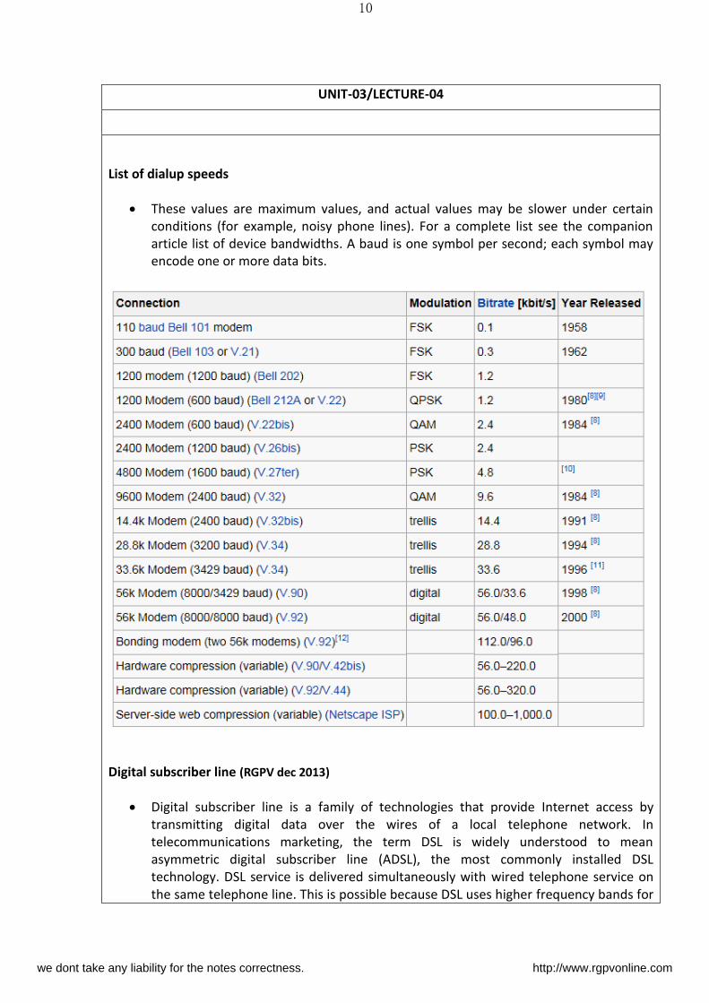
List of dialup speeds
These values are maximum values, and actual values may be slower under certain
conditions (for example, noisy phone lines). For a complete list see the companion
article list of device bandwidths. A baud is one symbol per second; each symbol may
encode one or more data bits.
Digital subscriber line (RGPV dec 2013)
Digital subscriber line is a family of technologies that provide Internet access by
transmitting digital data over the wires of a local telephone network. In
telecommunications marketing, the term DSL is widely understood to mean
asymmetric digital subscriber line (ADSL), the most commonly installed DSL
technology. DSL service is delivered simultaneously with wired telephone service on
the same telephone line. This is possible because DSL uses higher frequency bands for
we dont take any liability for the notes correctness. http://www.rgpvonline.com
11
data. On the customer premises, a DSL filter on each non-DSL outlet blocks any high
frequency interference, to enable simultaneous use of the voice and DSL services.
The bit rate of consumer DSL services typically ranges from 256 kbit/s to over 100
Mbit/s in the direction to the customer (downstream), depending on DSL technology,
line conditions, and service-level implementation. Bit rates of 1 Gbit/s have been
reached in trials. In ADSL, the data throughput in the upstream direction, (the
direction to the service provider) is lower, hence the designation of asymmetric
service. In symmetric digital subscriber line (SDSL) services, the downstream and
upstream data rates are equal.
When you connect to the Internet, you might connect through a regular modem,
through a local-area network connection in your office, through a cable modem or
through a digital subscriber line (DSL) connection. DSL is a very high-speed
connection that uses the same wires as a regular telephone line.
Advantages of DSL:
You can leave your Internet connection open and still use the phone line for voice
calls.
The speed is much higher than a regular modem
DSL doesn't necessarily require new wiring; it can use the phone line you already
have.
The company that offers DSL will usually provide the modem as part of the
installation.
Disadvantages:
A DSL connection works better when you are closer to the provider's central office.
The farther away you get from the central office, the weaker the signal becomes.
The connection is faster for receiving data than it is for sending data over the Internet.
The service is not available everywhere.
Telephone Lines
If you have read How Telephones Work, then you know that a standard telephone
installation in the United States consists of a pair of copper wires that the phone
company installs in your home. The copper wires have lots of room for carrying more
than your phone conversations -- they are capable of handling a much greater
bandwidth, or range of frequencies, than that demanded for voice. DSL exploits this
"extra capacity" to carry information on the wire without disturbing the line's ability
to carry conversations. The entire plan is based on matching particular frequencies to
specific tasks.
To understand DSL, you first need to know a couple of things about a normal
telephone line the kind that telephone professionals call POTS, for Plain Old
Telephone Service. One of the ways that POTS makes the most of the telephone
company's wires and equipment is by limiting the frequencies that the switches,
telephones and other equipment will carry. Human voices, speaking in normal
conversational tones, can be carried in a frequency range of 0 to 3,400 Hertz (cycles
we dont take any liability for the notes correctness. http://www.rgpvonline.com
12
per second -- see How Telephones Work for a great demonstration of this). This range
of frequencies is tiny. For example, compare this to the range of most stereo
speakers, which cover from roughly 20 Hertz to 20,000 Hertz. And the wires
themselves have the potential to handle frequencies up to several million Hertz in
most cases.
The use of such a small portion of the wire's total bandwidth is historical remember
that the telephone system has been in place, using a pair of copper wires to each
home, for about a century. By limiting the frequencies carried over the lines, the
telephone system can pack lots of wires into a very small space without worrying
about interference between lines. Modern equipment that sends digital rather than
analog data can safely use much more of the telephone line's capacity. DSL does just
that.
A DSL internet connection is one of many effective communication tools for keeping
employees in touch with the office
S.NO RGPV QUESTIONS Year Marks
Q.1 Discuss DSL with its advantages and
disadvantages.
DEC2013
4
we dont take any liability for the notes correctness. http://www.rgpvonline.com
13
UNIT-03/LECTURE-05
ADSL (RGPV dec 2012)
Asymmetric digital subscriber line (ADSL) is a type of digital subscriber line (DSL)
technology, a data communications technology that enables faster data transmission
over copper telephone lines than a conventional voiceband modem can provide. It
does this by utilizing frequencies that are not used by a voice telephone call. A
splitter, or DSL filter, allows a single telephone connection to be used for both ADSL
service and voice calls at the same time. ADSL can generally only be distributed over
short distances from the telephone exchange (the last mile), typically less than 4
kilometres , but has been known to exceed 8 kilometres if the originally laid wire
gauge allows for further distribution.
At the telephone exchange the line generally terminates at a digital subscriber line
access multiplexer (DSLAM) where another frequency splitter separates the voice
band signal for the conventional phone network. Data carried by the ADSL are
typically routed over the telephone company's data network and eventually reach a
conventional Internet Protocol network.
FDD uses two separate frequency bands, referred to as the upstream and
downstream bands. The upstream band is used for communication from the end user
to the telephone central office. The downstream band is used for communicating
from the central office to the end user.
DSL
Currently, most ADSL communication is full-duplex. Full-duplex ADSL communication
is usually achieved on a wire pair by either frequency-division duplex (FDD), echo-
cancelling duplex (ECD), or time-division duplex (TDD). FDD uses two separate
frequency bands, referred to as the upstream and downstream bands. The upstream
band is used for communication from the end user to the telephone central office.
The downstream band is used for communicating from the central office to the end
user.
we dont take any liability for the notes correctness. http://www.rgpvonline.com
14
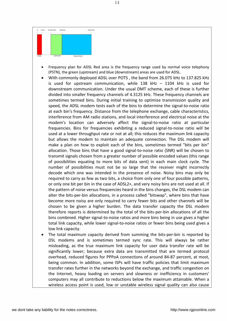
Frequency plan for ADSL Red area is the frequency range used by normal voice telephony
(PSTN), the green (upstream) and blue (downstream) areas are used for ADSL.
With commonly deployed ADSL over POTS , the band from 26.075 kHz to 137.825 kHz
is used for upstream communication, while 138 kHz – 1104 kHz is used for
downstream communication. Under the usual DMT scheme, each of these is further
divided into smaller frequency channels of 4.3125 kHz. These frequency channels are
sometimes termed bins. During initial training to optimize transmission quality and
speed, the ADSL modem tests each of the bins to determine the signal-to-noise ratio
at each bin's frequency. Distance from the telephone exchange, cable characteristics,
interference from AM radio stations, and local interference and electrical noise at the
modem's location can adversely affect the signal-to-noise ratio at particular
frequencies. Bins for frequencies exhibiting a reduced signal-to-noise ratio will be
used at a lower throughput rate or not at all; this reduces the maximum link capacity
but allows the modem to maintain an adequate connection. The DSL modem will
make a plan on how to exploit each of the bins, sometimes termed "bits per bin"
allocation. Those bins that have a good signal-to-noise ratio (SNR) will be chosen to
transmit signals chosen from a greater number of possible encoded values (this range
of possibilities equating to more bits of data sent) in each main clock cycle. The
number of possibilities must not be so large that the receiver might incorrectly
decode which one was intended in the presence of noise. Noisy bins may only be
required to carry as few as two bits, a choice from only one of four possible patterns,
or only one bit per bin in the case of ADSL2+, and very noisy bins are not used at all. If
the pattern of noise versus frequencies heard in the bins changes, the DSL modem can
alter the bits-per-bin allocations, in a process called "bitswap", where bins that have
become more noisy are only required to carry fewer bits and other channels will be
chosen to be given a higher burden. The data transfer capacity the DSL modem
therefore reports is determined by the total of the bits-per-bin allocations of all the
bins combined. Higher signal-to-noise ratios and more bins being in use gives a higher
total link capacity, while lower signal-to-noise ratios or fewer bins being used gives a
low link capacity.
The total maximum capacity derived from summing the bits-per-bin is reported by
DSL modems and is sometimes termed sync rate. This will always be rather
misleading, as the true maximum link capacity for user data transfer rate will be
significantly lower; because extra data are transmitted that are termed protocol
overhead, reduced figures for PPPoA connections of around 84-87 percent, at most,
being common. In addition, some ISPs will have traffic policies that limit maximum
transfer rates further in the networks beyond the exchange, and traffic congestion on
the Internet, heavy loading on servers and slowness or inefficiency in customers'
computers may all contribute to reductions below the maximum attainable. When a
wireless access point is used, low or unstable wireless signal quality can also cause
we dont take any liability for the notes correctness. http://www.rgpvonline.com
15
reduction or fluctuation of actual speed.
In fixed-rate mode, the sync rate is predefined by the operator and the DSL modem chooses a
bits-per-bin allocation that yields an approximately equal error rate in each bin.In variable-
rate mode, the bits-per-bin are chosen to maximize the sync rate, subject to a tolerable error
risk. These choices can either be conservative, where the modem chooses to allocate fewer
bits per bin than it possibly could, a choice which makes for a slower connection, or less
conservative in which more bits per bin are chosen in which case there is a greater risk case of
error should future signal-to-noise ratios deteriorate to the point where the bits-per-bin
allocations chosen are too high to cope with the greater noise present. This conservatism,
involving a choice of using fewer bits per bin as a safeguard against future noise increases, is
reported as the signal to-noise ratio margin or SNR margin. The telephone exchange can
indicate a suggested SNR margin to the customer's DSL modem when it initially
connects, and the modem may make its bits-per-bin allocation plan accordingly. A
high SNR margin will mean a reduced maximum throughput, but greater reliability
and stability of the connection. A low SNR margin will mean high speeds, provided the
noise level does not increase too much; otherwise, the connection will have to be
dropped and renegotiated (resynced). ADSL2+ can better accommodate such
circumstances, offering a feature termed seamless rate adaptation (SRA), which can
accommodate changes in total link capacity with less disruption to communications.
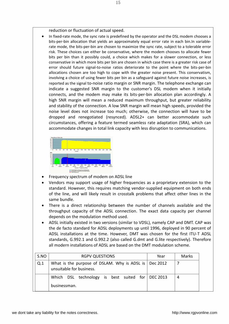
Frequency spectrum of modem on ADSL line
Vendors may support usage of higher frequencies as a proprietary extension to the
standard. However, this requires matching vendor-supplied equipment on both ends
of the line, and will likely result in crosstalk problems that affect other lines in the
same bundle.
There is a direct relationship between the number of channels available and the
throughput capacity of the ADSL connection. The exact data capacity per channel
depends on the modulation method used.
ADSL initially existed in two versions (similar to VDSL), namely CAP and DMT. CAP was
the de facto standard for ADSL deployments up until 1996, deployed in 90 percent of
ADSL installations at the time. However, DMT was chosen for the first ITU-T ADSL
standards, G.992.1 and G.992.2 (also called G.dmt and G.lite respectively). Therefore
all modern installations of ADSL are based on the DMT modulation scheme.
S.NO RGPV QUESTIONS Year Marks
Q.1 What is the purpose of DSLAM. Why is ADSL is
unsuitable for business.
Dec 2012 7
Which DSL technology is best suited for
businessman.
DEC 2013 4
we dont take any liability for the notes correctness. http://www.rgpvonline.com
16
UNIT-03/LECTURE-06
SDSL
Symmetric digital subscriber line (SDSL) can have two meanings:
In the wider sense it is a collection of Internet access technologies based on DSL that
offer symmetric bandwidth upstream and downstream, including IDSL, HDSL, HDSL2,
G.SHDSL, and the SDSL variant below. It is considered the opposite of asymmetric
digital subscriber line (ADSL) technologies where the upstream bandwidth is lower
than the downstream bandwidth.
In the narrow sense SDSL is a particular proprietary and non-standardized DSL variant
that supports data only on a single line and does not support analog calls, see below.
Proprietary SDSL technology
SDSL is a rate-adaptive digital subscriber line (DSL) variant with T1/E1-like data rates
(T1: 1.544 Mbit/s, E1: 2.048 Mbit/s). It runs over one pair of copper wires, with a
maximum range of 10,000 feet (3,000 m). It cannot co-exist with a conventional voice
service on the same pair as it takes over the entire bandwidth.
VDSL (RGPV dec 2012)
Very-high-bit-rate digital subscriber line (VDSL or VHDSL) is a digital subscriber line
(DSL) technology providing data transmission faster than ADSL over a single flat
untwisted or twisted pair of copper wires (up to 52 Mbit/s downstream and 16 Mbit/s
upstream), and on coaxial cable (up to 85 Mbit/s down- and upstream) using the
frequency band from 25 kHz to 12 MHz. These rates mean that VDSL is capable of
supporting applications such as high-definition television, as well as telephone
services (voice over IP) and general Internet access, over a single connection. VDSL is
deployed over existing wiring used for analog telephone service and lower-speed DSL
connections. This standard was approved by ITU in November 2001.
Second-generation systems (VDSL2; ITU-T G.993.2 approved in February 2006) use
frequencies of up to 30 MHz to provide data rates exceeding 100 Mbit/s
simultaneously in both the upstream and downstream directions. The maximum
available bit rate is achieved at a range of about 300 meters; performance degrades
as the loop attenuation increases.
VDSL standards
A VDSL connection uses up to seven frequency bands, so one can allocate the data
rate between upstream and downstream differently depending on the service
offering and spectrum regulations. First generation VDSL standard specified both
quadrature amplitude modulation (QAM) and discrete multi-tone modulation (DMT).
we dont take any liability for the notes correctness. http://www.rgpvonline.com
17
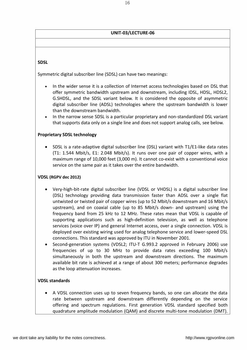
In 2006, ITU-T standardized VDSL in recommendation G.993.2 which specified only
DMT modulation for VDSL2.
Multiplexing
In telecommunications and computer networks, multiplexing is a method by which
multiple analog message signals or digital data streams are combined into one signal
over a shared medium. The aim is to share an expensive resource. For example, in
telecommunications, several telephone calls may be carried using one wire.
Multiplexing originated in telegraphy in the 1870s, and is now widely applied in
communications. In telephony, George Owen Squier is credited with the development
of telephone carrier multiplexing in 1910.
The multiplexed signal is transmitted over a communication channel, which may be a
physical transmission medium. The multiplexing divides the capacity of the high-level
communication channel into several low-level logical channels, one for each message
signal or data stream to be transferred. A reverse process, known as demultiplexing,
can extract the original channels on the receiver side.
A device that performs the multiplexing is called a multiplexer (MUX), and a device
that performs the reverse process is called a demultiplexer (DEMUX or DMX).
Inverse multiplexing (IMUX) has the opposite aim as multiplexing, namely to break
one data stream into several streams, transfer them simultaneously over several
communication channels, and recreate the original data stream.
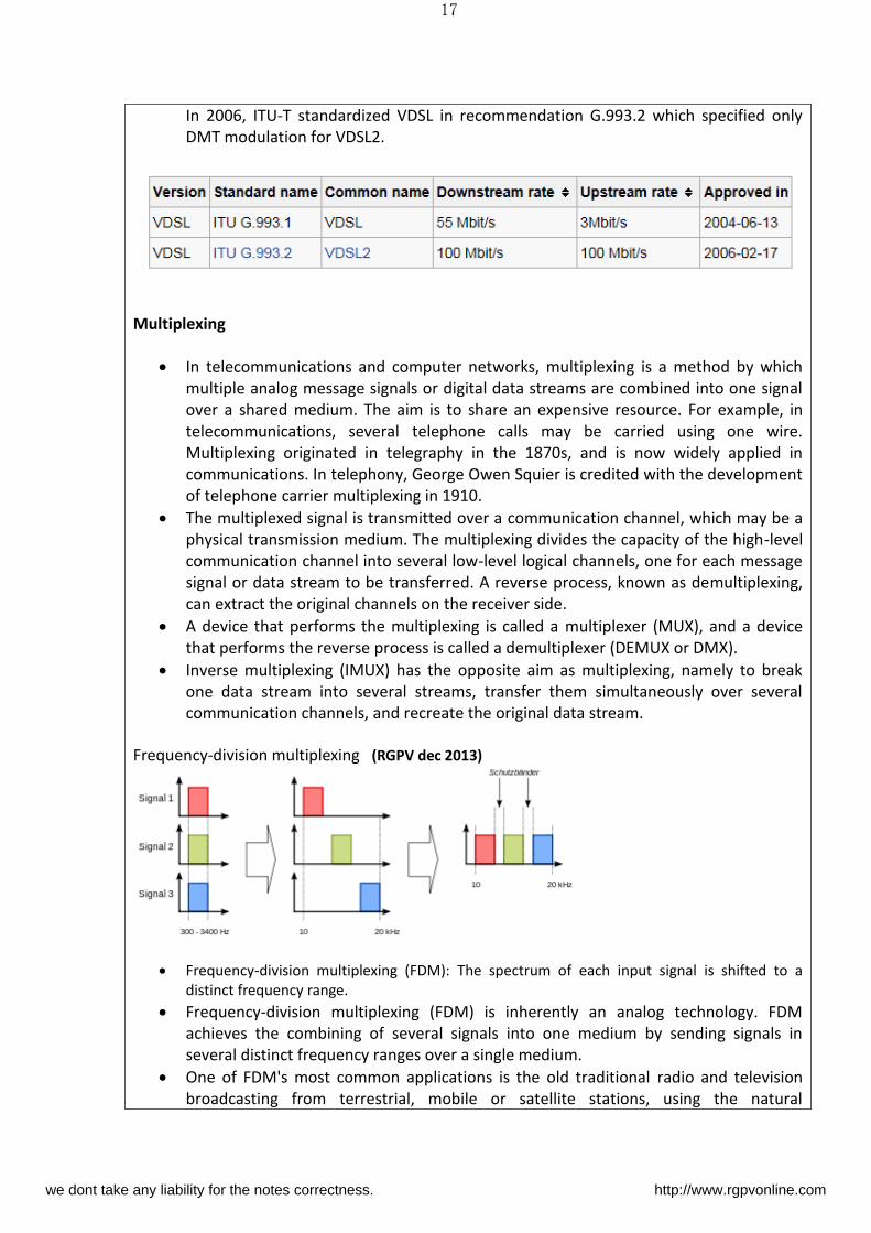
Frequency-division multiplexing (RGPV dec 2013)
Frequency-division multiplexing (FDM): The spectrum of each input signal is shifted to a
distinct frequency range.
Frequency-division multiplexing (FDM) is inherently an analog technology. FDM
achieves the combining of several signals into one medium by sending signals in
several distinct frequency ranges over a single medium.
One of FDM's most common applications is the old traditional radio and television
broadcasting from terrestrial, mobile or satellite stations, using the natural
we dont take any liability for the notes correctness. http://www.rgpvonline.com
18
atmosphere of Earth, or the cable television. Only one cable reaches a customer's
residential area, but the service provider can send multiple television channels or
signals simultaneously over that cable to all subscribers without interference.
Receivers must tune to the appropriate frequency (channel) to access the desired
signal.
S.NO RGPV QUESTION YEAR MARKS
Q.1 Explain the working principle of VDSL. DEC 2012 7
Q.2 Differentiate between FDM TDM and
FDM
DEC 2013 7
we dont take any liability for the notes correctness. http://www.rgpvonline.com
19
UNIT-03/LECTURE-07
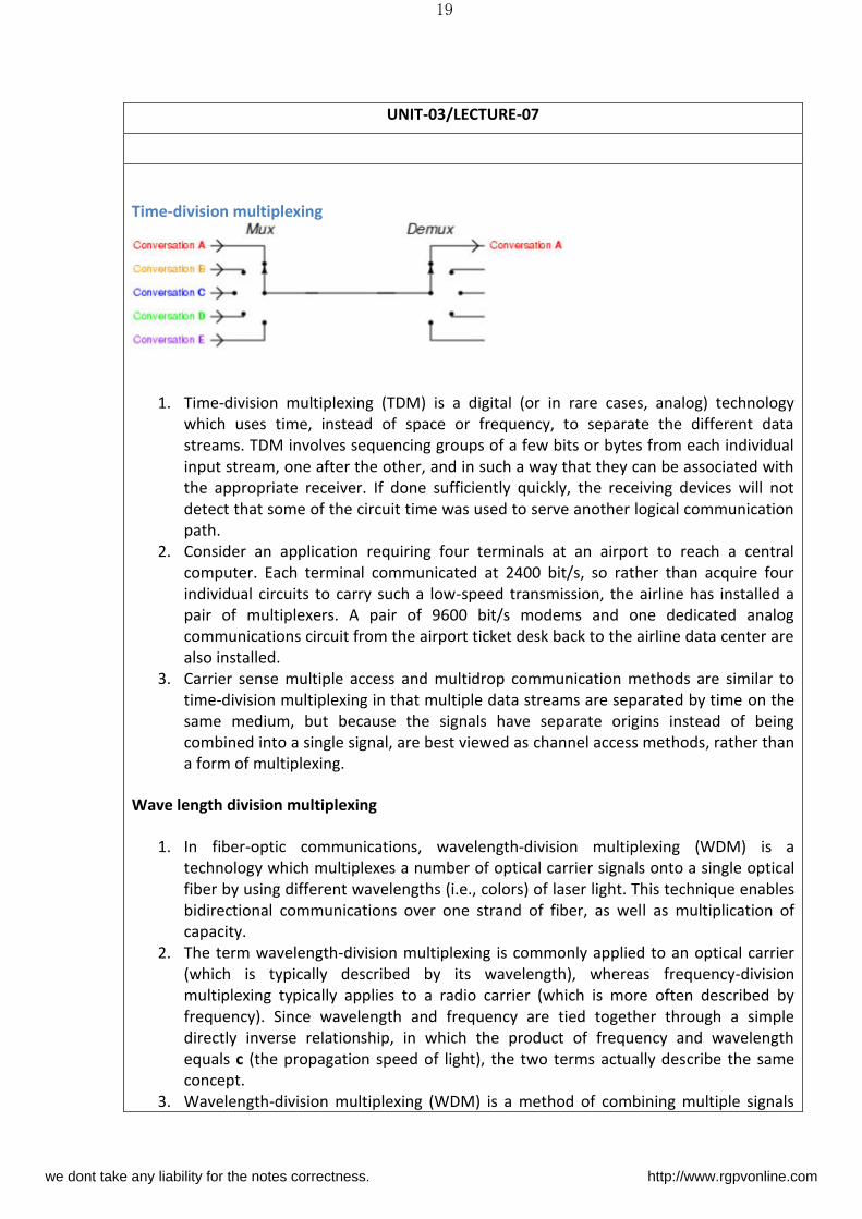
Time-division multiplexing
1. Time-division multiplexing (TDM) is a digital (or in rare cases, analog) technology
which uses time, instead of space or frequency, to separate the different data
streams. TDM involves sequencing groups of a few bits or bytes from each individual
input stream, one after the other, and in such a way that they can be associated with
the appropriate receiver. If done sufficiently quickly, the receiving devices will not
detect that some of the circuit time was used to serve another logical communication
path.
2. Consider an application requiring four terminals at an airport to reach a central
computer. Each terminal communicated at 2400 bit/s, so rather than acquire four
individual circuits to carry such a low-speed transmission, the airline has installed a
pair of multiplexers. A pair of 9600 bit/s modems and one dedicated analog
communications circuit from the airport ticket desk back to the airline data center are
also installed.
3. Carrier sense multiple access and multidrop communication methods are similar to
time-division multiplexing in that multiple data streams are separated by time on the
same medium, but because the signals have separate origins instead of being
combined into a single signal, are best viewed as channel access methods, rather than
a form of multiplexing.
Wave length division multiplexing
1. In fiber-optic communications, wavelength-division multiplexing (WDM) is a
technology which multiplexes a number of optical carrier signals onto a single optical
fiber by using different wavelengths (i.e., colors) of laser light. This technique enables
bidirectional communications over one strand of fiber, as well as multiplication of
capacity.
2. The term wavelength-division multiplexing is commonly applied to an optical carrier
(which is typically described by its wavelength), whereas frequency-division
multiplexing typically applies to a radio carrier (which is more often described by
frequency). Since wavelength and frequency are tied together through a simple
directly inverse relationship, in which the product of frequency and wavelength
equals c (the propagation speed of light), the two terms actually describe the same
concept.
3. Wavelength-division multiplexing (WDM) is a method of combining multiple signals
we dont take any liability for the notes correctness. http://www.rgpvonline.com
20
on laser beams at various infared (IR) wavelengths for transmission along fiber optic
media. Each laser is modulated by an independent set of signals. Wavelength-
sensitive filters, the IR analog of visible-light color filters, are used at the receiving
end.
4. WDM is similar to frequency-division multiplexing (FDM). But instead of taking place
at radio frequencies (RF), WDM is done in the IR portion of the electromagnetic
spectrum. Each IR channel carries several RF signals combined by means of FDM or
time-division multiplexing (TDM). Each multiplexed IR channel is separated, or
demultiplexed, into the original signals at the destination. Using FDM or TDM in each
IR channel in combination with WDM or several IR channels, data in different formats
and at different speeds can be transmitted simultaneously on a single fiber.
5. In early WDM systems, there were two IR channels per fiber. At the destination, the IR
channels were demultiplexed by a dichroic (two-wavelength) filter with a cutoff
wavelength approximately midway between the wavelengths of the two channels. It
soon became clear that more than two multiplexed IR channels could be
demultiplexed using cascaded dichroic filters, giving rise to coarse wavelength-
division multiplexing (CWDM) and dense wavelength-division multiplexing (DWDM).
In CWDM, there are usually eight different IR channels, but there can be up to 18. In
DWDM, there can be dozens. Because each IR channel carries its own set of
multiplexed RF signals, it is theoretically possible to transmit combined data on a
single fiber at a total effective speed of several hundred gigabitsper second (Gbps).
6. The use of WDM can multiply the effective bandwidth of a fiber optic communications
system by a large factor, but its cost must be weighed against the alternative of using
multiple fibers bundled into a cable. A fiber optic repeater device called the erbium
amplifier can make WDM a cost-effective long-term solution.
Pulse code modulation
1. Pulse code modulation (PCM) is a digital scheme for transmitting analogdata. The
signals in PCM are binary; that is, there are only two possible states, represented by
logic 1 (high) and logic0 (low). This is true no matter how complex the analog
waveform happens to be. Using PCM, it is possible to digitize all forms of analog data,
including full-motion video, voices, music, telemetry, and virtual reality (VR).
2. To obtain PCM from an analog waveform at the source (transmitter end) of a
communications circuit, the analog signal amplitude is sampled (measured) at regular
time intervals.The sampling rate, or number of samples per second, is several times
the maximum frequency of the analog waveform in cycles per second or hertz. The
instantaneous amplitude of the analog signal at each sampling is rounded off to the
nearest of several specific, predetermined levels. This process is called quantization.
The number of levels is always a power of 2.for example, 8, 16, 32, or 64. These
numbers can be represented by three, four, five, or six binary digits (bits)respectively.
The output of a pulse code modulator is thus a series of binary numbers, each
represented by some power of 2bits.
3. At the destination (receiver end) of the communications circuit, a pulse code
demodulator converts the binary numbers back into pulses having the same quantum
levels as those in the modulator. These pulses are further processed to restore the
we dont take any liability for the notes correctness. http://www.rgpvonline.com
21
original analog waveform.
PDH (RGPV dec 2012/2013)
1. The plesiochronous digital hierarchy (PDH) is a technology used in
telecommunications networks to transport large quantities of data over digital
transport equipment such as fibre optic and microwave radio systems. The term
plesiochronous is derived from Greek plēsios, meaning near, and chronos, time, and
refers to the fact that PDH networks run in a state where different parts of the
network are nearly, but not quite perfectly, synchronised.
2. PDH is typically being replaced by synchronous digital hierarchy (SDH) or synchronous
optical networking (SONET) equipment in most telecommunications networks.
3. PDH allows transmission of data streams that are nominally running at the same rate,
but allowing some variation on the speed around a nominal rate. By analogy, any two
watches are nominally running at the same rate, clocking up 60 seconds every minute.
However, there is no link between watches to guarantee they run at exactly the same
rate, and it is highly likely that one is running slightly faster than the other.
Implementation
1. The data rate is controlled by a clock in the equipment generating the data. The rate is
allowed to vary by ±50 ppm of 2.048 Kbit/s (according to ITU-T recommendation. This
means that different data streams can be (probably are) running at slightly different
rates to one another.
2. In order to move multiple data streams from one place to another, they are
multiplexed in groups of four. This is done by taking 1 bit from stream #1, followed by
1 bit from stream #2, then #3, then #4. The transmitting multiplexer also adds
additional bits in order to allow the far end receiving multiplexer to decode which bits
belong to which data stream, and so correctly reconstitute the original data streams.
These additional bits are called "justification" or "stuffing" bits.
3. Because each of the four data streams is not necessarily running at the same rate,
some compensation has to be introduced. The transmitting multiplexer combines the
four data streams assuming that they are running at their maximum allowed rate. This
means that occasionally, (unless the 2 Mbit/s really is running at the maximum rate)
the multiplexer will look for the next bit but it will not have arrived. In this case, the
multiplexer signals to the receiving multiplexer that a bit is "missing". This allows the
receiving multiplexer to correctly reconstruct the original data for each of the four 2
Mbit/s data streams, and at the correct, different, plesiochronous rates.
4. The resulting data stream from the above process runs at 8.448 Mbit/s (about 8
Mbit/s). Similar techniques are used to combine four × 8 Mbit/s together, plus bit
stuffing, giving 34 Mbit/s. Four × 34 Mbit/s, gives 140. Four × 140 gives 565.
S.NO RGPV QUESTION YEAR MARKS
Q.1 Explain the working principle of VDSL. DEC 2012 7
Q.2 Differentiate between FDM TDM and
FDM
DEC 2013 7
we dont take any liability for the notes correctness. http://www.rgpvonline.com
22
UNIT-03/LECTURE-08
Difference Between Pdh And Sdh (RGPV dec 2011/2013)
SDH which stands for Synchronous Digital Hierarchy was developed recently and was made to
do away with PDH's weaknesses while PDH which stands for Plesiochronous Digital Hierarchy,
is a type that is used for of data transferring data mainly in large file groups. PDH was made
around 1990 is cheap and compatible compared to SDH.
Stm 1 frame
STM-1
The STM-1 (Synchronous Transport Module level-1) is the SDH ITU-T fiber optic
network transmission standard. It has a bit rate of 155.52 Mbit/s. Higher levels go up
by a factor of 4 at a time: the other currently supported levels are STM-4, STM-16,
STM-64 and STM-256. Beyond this we have wavelength-division multiplexing (WDM)
commonly used in submarine cabling.
Frame structure
The STM-1 frame is the basic transmission format for SDH (Synchronous Digital
Hierarchy). A STM-1 frame has a byte-oriented structure with 9 rows and 270 columns
of bytes, for a total of 2,430 bytes (9 rows * 270 columns = 2430 bytes). Each byte
corresponds to a 64kbit/s channel.
we dont take any liability for the notes correctness. http://www.rgpvonline.com
23
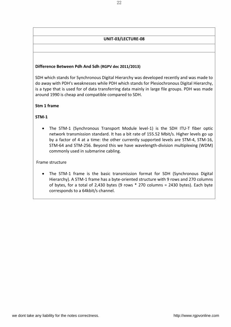
TOH: Transport Overhead (RSOH + AU4P + MSOH)
MSOH: Multiplex Section Overhead
RSOH: Regeneration Section Overhead
AU4P: AU-4 Pointers
VC4: Virtual Container-4 payload (POH + VC-4 Data)
POH: Path Overhead
Frame characteristics
The STM-1 base frame is structured with the following characteristics:
Length: 270 column × 9 row = 2430 bytes
Byte: 1-byte = 64kbit/s speech channel
Duration Fra e repetitio ti e : 5 μs i.e. 8 fra e/s
Rate (Frame capacity): 2430 × 8 × 8000 = 155.520 Mbit/s
Payload = 2349bytes × 8bits × 8000frames/sec = 150.336 Mbit/s
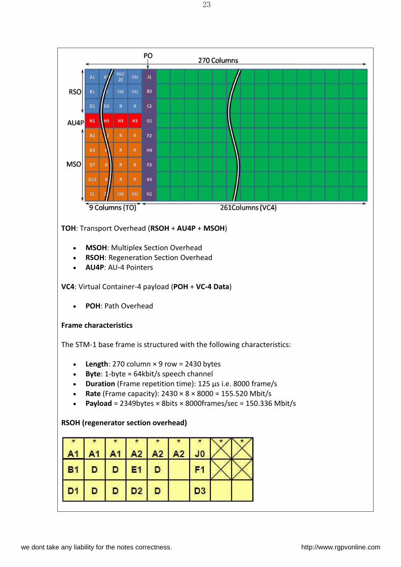
RSOH (regenerator section overhead)
we dont take any liability for the notes correctness. http://www.rgpvonline.com
24
1st row = Unscrambled bytes. Their contents should therefore be monitored
X = Bytes reserved for national use
D = Bytes depending on the medium (satellite, radio relay system, ...)
The Regenerator Section OverHead uses the first three rows & nine columns in the STM-1
frame
A1, A2 The Frame Alignment Word is used to recognize the beginning of an STM-N
frame
A1: 1111 0110 = F6 (HEX)
A2: 0010 1000 = 28 (HEX)
J0: Path Trace. It is used to give a path through an SDH Network a "Name". This
message (Name) enables the receiver to check the continuity of its connection with
the desired transmitter
B1: Bit Error Monitoring. The B1 Byte contains the result of the parity check of the
previous STM frame, after scrambling of the actual STM frame. This check is carried
out with a Bit Interleaved Parity check (BIP-8).
E1 Engineering Orderwire (EOW). It can be used to transmit speech signals between
Regenerator Sections for operating and maintenance purposes
F1 User Channel. It is used to transmit data and speech for service and maintenance
D1 to D3 Data Communication Channel at 192 kbit/s (DCCR). This channel is used to
transmit management information via the STM-N frames
S.NO RGPV QUESTION YEAR MARKS
Q.1 Discuss the standards of sdh
hierarchy.
Dec2013
Dec2011
7
4
we dont take any liability for the notes correctness. http://www.rgpvonline.com
25
UNIT-03/LECTURE-09
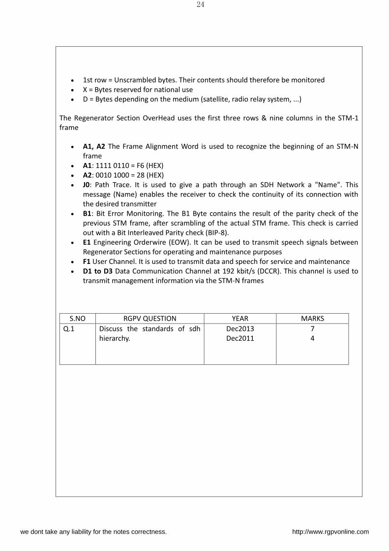
MSOH (multiplex section overhead) (RGPV dec 2011)
X = Bytes reserved for national use.
The Multiplex Section OverHead uses the 5th through 9th rows, and first 9 columns in the
STM-1 frame.
B2 : Bit Error Monitoring. The B2 Bytes contains the result of the parity check of the
previous STM frame, except the RSOH, before scrambling of the actual STM frame.
This check is carried out with a Bit Interleaved Parity check (BIP24)
K1, K2 Automatic Protection Switching (APS). In case of a failure, the STM frames can
be routed new with the help of the K1, K2 Bytes through the SDH Network. Assigned
to the multiplexing section protection (MSP) protocol
K2 (Bit6,7,8) MS_RDI: Multiplex Section Remote Defect Indication (former MS_FERF:
Multiplex Section Far End Receive Failure)
D4 to D12 Data Communication Channel at 576 kbit/s (DCCM). (See also D1-D3 in
RSOH above)
S1 (Bit 5 - 8) Synchronization quality level:
o 0000 Quality unknown
o 0010 G.811 10-11/day frequency drift
o 0100 G.812T transit 10-9 /day frequency drift
o 1000 G.812L local 2*10-8/day frequency drift
o 1011 G.813 5*10-7/day frequency drift
o 1111 Not to be used for synchronization
E2 Engineering Orderwire (EOW). Same function as E1 in RSOH
M1 MS_REI: Multiplex Section Remote Error Indicator, number of interleaved bits
which have been detected to be erroneous in the received B2 bytes. (former
MS_FEBE: Multiplexing Section Far End Block Errored)
Z1, Z2 Spare bytes
we dont take any liability for the notes correctness. http://www.rgpvonline.com
26
Question:
Five channels each with a 100khz bandwidth are to be multiplied together.What is the
minimum bandwidth of the link if there is a need for a guard band of 10 khz between the
channels to prevent interference.
Solution:
For five channels we need at least four guard bands.This means that the required bandwidth
is at least 5 × 100 ÷ 4 × 10 = 540 khz.
S.NO RGPV QUESTION YEAR MARKS
Q.1 Define multiplex section
overhead.
Dec 2011 4
we dont take any liability for the notes correctness. http://www.rgpvonline.com

27
we dont take any liability for the notes correctness. http://www.rgpvonline.com


![UNIT - 2 Unit- 02 /Lecture-01 - rgpvonline.com · 2019. 6. 18. · Unit-02/Lecture-02 [RGPV JUNE(2002)] [7] S.NO RGPV QUESTIONS Year Marks Q.1 Find the smallest positive root of the](https://img.pdfslide.us/doc/110x75/6129a31ecb6818393155879c/unit-2-unit-02-lecture-01-2019-6-18-unit-02lecture-02-rgpv-june2002.jpg)

![Unit - 05 Information storage on cloud Unit 05/Lecture - 01 · Cloud computing t [Rgpv /dec 2014(2), Rgpv/dec 2013(10), Rgpv/dec 2012(10)] Cloud computing is a term used to refer](https://img.pdfslide.us/doc/110x75/5e6784b44fbbb40153067da9/unit-05-information-storage-on-cloud-unit-05lecture-01-cloud-computing-t-rgpv.jpg)
![UNIT 03 Planes Unit-03/Lecture-01 · 1 UNIT – 03 Planes Unit-03/Lecture-01 Introduction[RGPV/ June-2002,04,06,11 Dec.2001,02,03,06,10,11]- In this chapter, we deal with two dimensional](https://img.pdfslide.us/doc/110x75/5f41268a10c58a1be71ff2b0/unit-03-planes-unit-03lecture-01-1-unit-a-03-planes-unit-03lecture-01-introductionrgpv.jpg)
![UNIT t Logical Addressing[RGPV/Jun 2014]](https://img.pdfslide.us/doc/110x75/61ed062e7a02dc668f5863a8/unit-t-logical-addressingrgpvjun-2014.jpg)