Embed Size (px)
Citation preview
1
UNIT–01
UNIT-01/LECTURE-01
DATA COMMUNICATIONS
DATA COMMUNICATIONS
Transmission of signals in a reliable and efficient matter.
COMMUNICATION MODEL
The purpose of a communications system is to exchange data between two entities.
Source:
Entity that generates data.For example a person who speaks into the phone, or a
computer sending data to the modem.
Transmitter:
A device to transform/encode the signal generated by the source.The transformed
signal is actually sent over the transmission system.For example a modem transforms
digital data to analog signal that can be handled by the telephone network.
Transmission System (Channel):
Medium that allows the transfer of a signal from one point to another. For example a
telephone network for a computer/modem.
Receiver:
A device to decode the received signal for handling by destination device. For example
a modem converts the received analog data back to digital for the use by the
computer.
Destination:
Entity that finally uses the data. For example Computer on other end of a receiving
modem.
Data Communications:
Data communications is the transfer of information that is in digital form, before it
enters the communication system.
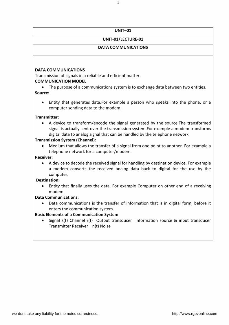
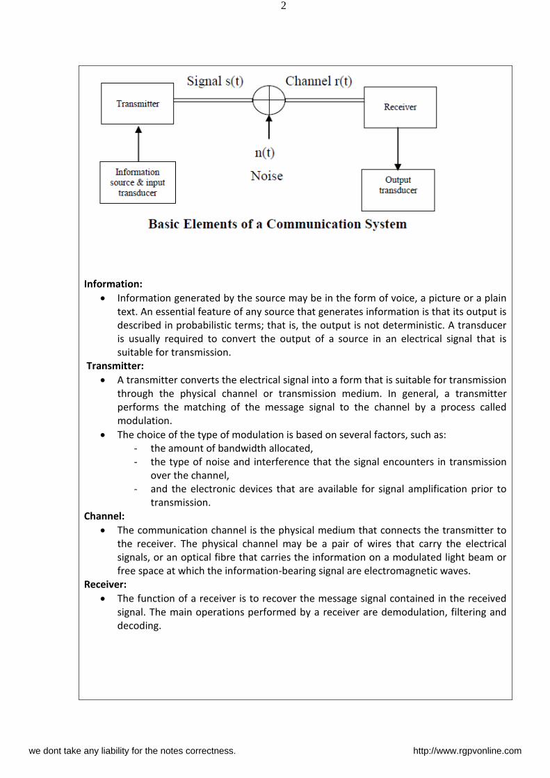
Basic Elements of a Communication System
Signal s(t) Channel r(t) Output transducer Information source & input transducer
Transmitter Receiver n(t) Noise
we dont take any liability for the notes correctness. http://www.rgpvonline.com
2
Information:
Information generated by the source may be in the form of voice, a picture or a plain
text. An essential feature of any source that generates information is that its output is
described in probabilistic terms; that is, the output is not deterministic. A transducer
is usually required to convert the output of a source in an electrical signal that is
suitable for transmission.
Transmitter:
A transmitter converts the electrical signal into a form that is suitable for transmission
through the physical channel or transmission medium. In general, a transmitter
performs the matching of the message signal to the channel by a process called
modulation.
The choice of the type of modulation is based on several factors, such as:
- the amount of bandwidth allocated,
- the type of noise and interference that the signal encounters in transmission
over the channel,
- and the electronic devices that are available for signal amplification prior to
transmission.
Channel:
The communication channel is the physical medium that connects the transmitter to
the receiver. The physical channel may be a pair of wires that carry the electrical
signals, or an optical fibre that carries the information on a modulated light beam or
free space at which the information-bearing signal are electromagnetic waves.
Receiver:
The function of a receiver is to recover the message signal contained in the received
signal. The main operations performed by a receiver are demodulation, filtering and
decoding.
we dont take any liability for the notes correctness. http://www.rgpvonline.com
3
UNIT-01/LECTURE-02
Analog And Digital Signals
Analog And Digital Signals:
The terms analog and digital correspond to continuous and discrete, respectively. These two
terms are frequently used in data communications.Analog data takes on continuous values
on some interval. The most familiar example of analog data is audio signal. Frequency
components of speech may be found between 20 Hz and 20 kHz. The basic speech energy is
concentrated between 300-3400 Hz. The frequencies up to 4000 Hz add very little to the
intelligibility of human ear. Another common example of analog data is video. The outputs of
many sensors, such as temperature and pressure sensors, are also examples of analog data.
Digital data takes on discrete values.Digital transmission is the transfer of information
through a medium in digital form. A digital signal can be transmitted only for a limited
distance.Data communications is the transfer of information that is in digital form, before it
enters the communication system.
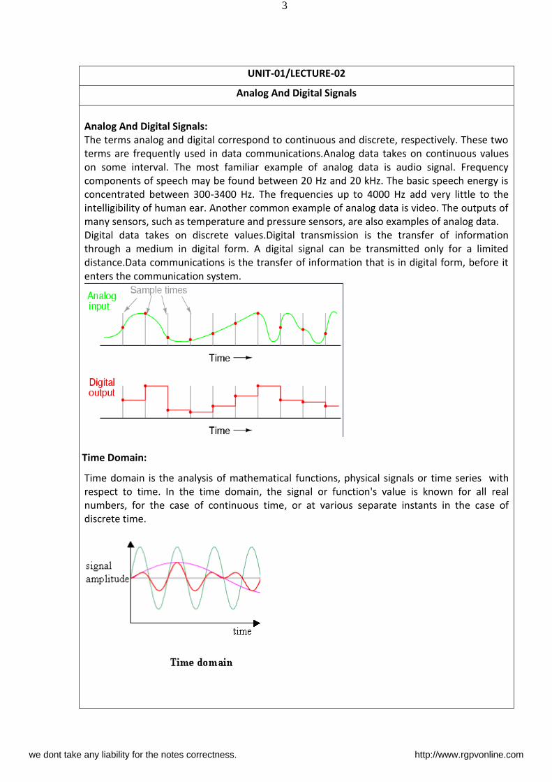
Time Domain:
Time domain is the analysis of mathematical functions, physical signals or time series with
respect to time. In the time domain, the signal or function's value is known for all real
numbers, for the case of continuous time, or at various separate instants in the case of
discrete time.
we dont take any liability for the notes correctness. http://www.rgpvonline.com
4
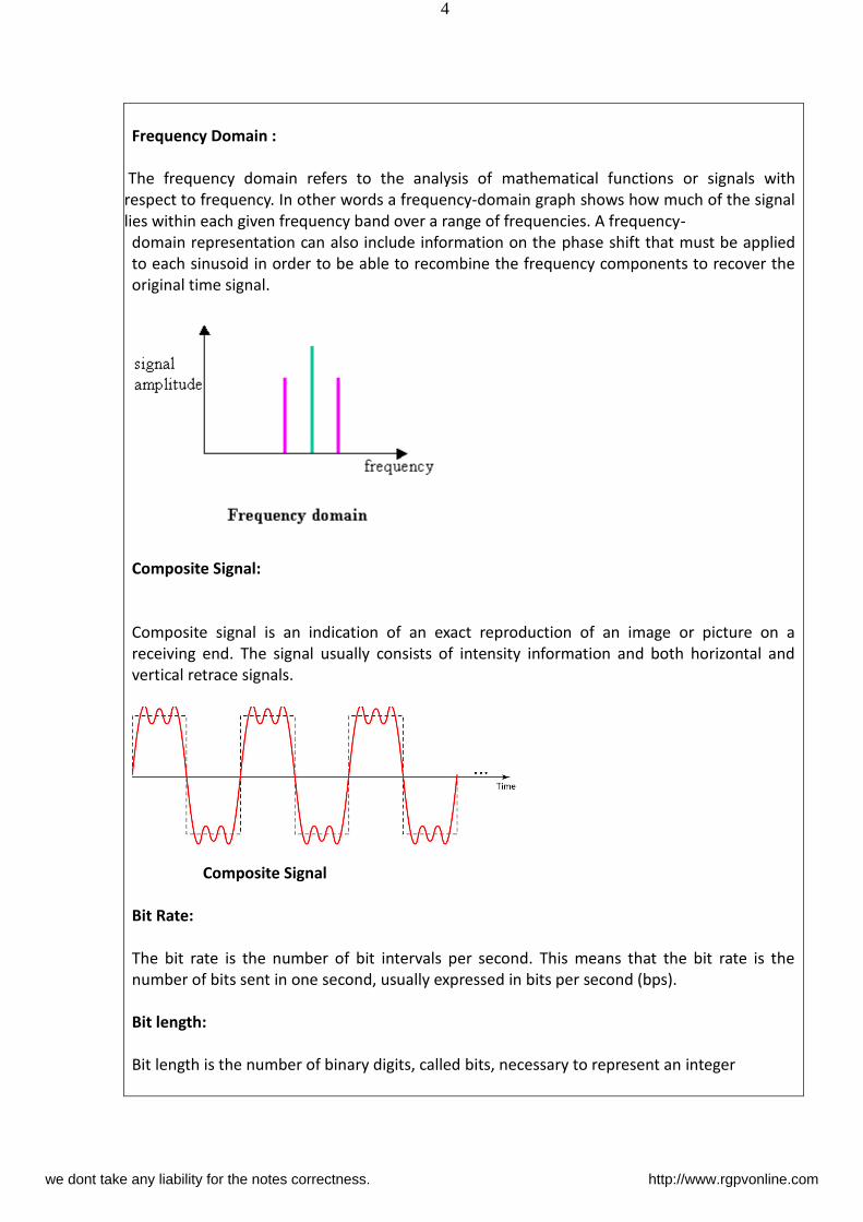
Frequency Domain :
The frequency domain refers to the analysis of mathematical functions or signals with
respect to frequency. In other words a frequency-domain graph shows how much of the signal
lies within each given frequency band over a range of frequencies. A frequency-
domain representation can also include information on the phase shift that must be applied
to each sinusoid in order to be able to recombine the frequency components to recover the
original time signal.
Composite Signal:
Composite signal is an indication of an exact reproduction of an image or picture on a
receiving end. The signal usually consists of intensity information and both horizontal and
vertical retrace signals.
Composite Signal
Bit Rate:
The bit rate is the number of bit intervals per second. This means that the bit rate is the
number of bits sent in one second, usually expressed in bits per second (bps).
Bit length:
Bit length is the number of binary digits, called bits, necessary to represent an integer
we dont take any liability for the notes correctness. http://www.rgpvonline.com
5
Bandwidth:
Width of the spectrum or band of frequencies containing energy of the signal.
In networking, we use the term bandwidth in two contexts.
The first, bandwidth in hertz, refers to the range of frequencies in a composite signal
or the range of frequencies that a channel can pass.
The second, bandwidth in bits per second, refers to the speed of bit transmission in a
channel or link. Often referred to as Capacity.
The bandwidth of a subscriber line is 4 kHz for voice or data. The bandwidth of this
line for data transmission
can be up to 56,000 bps using a sophisticated modem to change the digital signal to
analog.
If the telephone company improves the quality of the line and increases the bandwidth
to 8 kHz, we can send 112,000 bps by using the same technology.
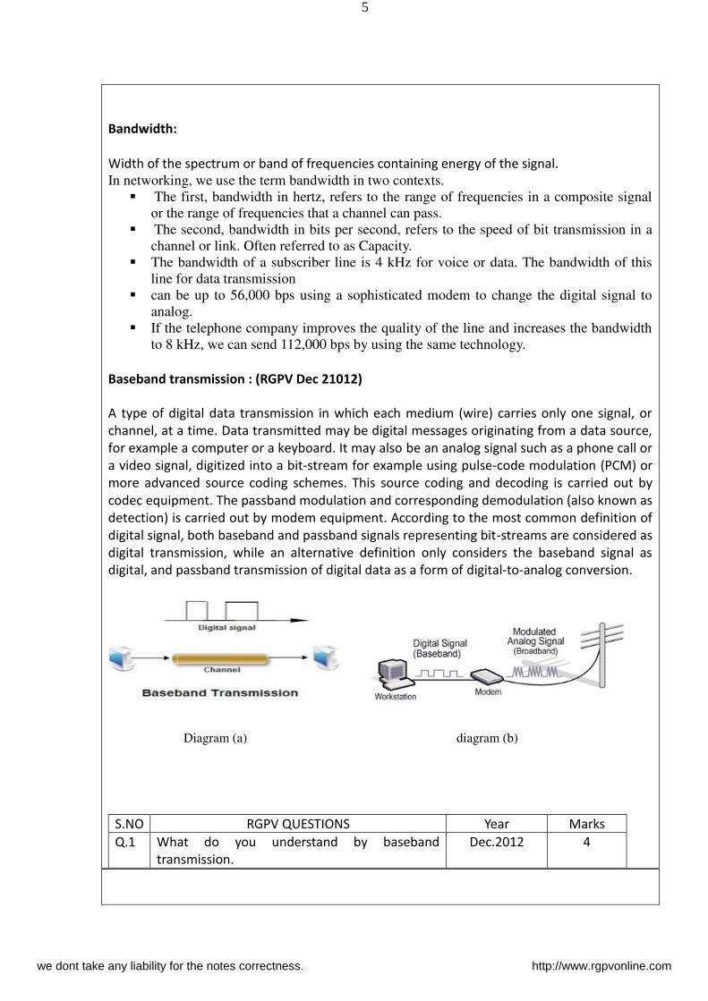
Baseband transmission : (RGPV Dec 21012)
A type of digital data transmission in which each medium (wire) carries only one signal, or
channel, at a time. Data transmitted may be digital messages originating from a data source,
for example a computer or a keyboard. It may also be an analog signal such as a phone call or
a video signal, digitized into a bit-stream for example using pulse-code modulation (PCM) or
more advanced source coding schemes. This source coding and decoding is carried out by
codec equipment. The passband modulation and corresponding demodulation (also known as
detection) is carried out by modem equipment. According to the most common definition of
digital signal, both baseband and passband signals representing bit-streams are considered as
digital transmission, while an alternative definition only considers the baseband signal as
digital, and passband transmission of digital data as a form of digital-to-analog conversion.
Diagram (a) diagram (b)
S.NO RGPV QUESTIONS Year Marks
Q.1 What do you understand by baseband
transmission.
Dec.2012 4
we dont take any liability for the notes correctness. http://www.rgpvonline.com
6
UNIT-01/LECTURE-03
Broadband Transmission
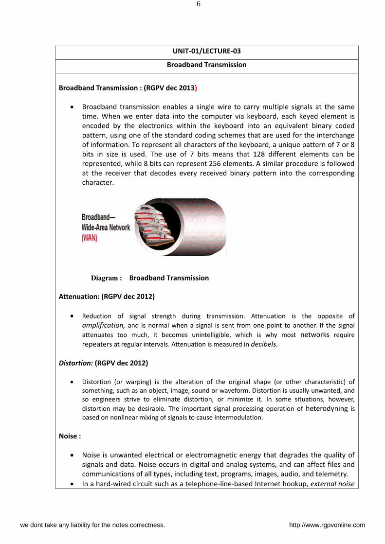
Broadband Transmission : (RGPV dec 2013)
Broadband transmission enables a single wire to carry multiple signals at the same
time. When we enter data into the computer via keyboard, each keyed element is
encoded by the electronics within the keyboard into an equivalent binary coded
pattern, using one of the standard coding schemes that are used for the interchange
of information. To represent all characters of the keyboard, a unique pattern of 7 or 8
bits in size is used. The use of 7 bits means that 128 different elements can be
represented, while 8 bits can represent 256 elements. A similar procedure is followed
at the receiver that decodes every received binary pattern into the corresponding
character.
Diagram : Broadband Transmission
Attenuation: (RGPV dec 2012)
Reduction of signal strength during transmission. Attenuation is the opposite of
amplification, and is normal when a signal is sent from one point to another. If the signal
attenuates too much, it becomes unintelligible, which is why most networks require
repeaters at regular intervals. Attenuation is measured in decibels.
Distortion: (RGPV dec 2012)
Distortion (or warping) is the alteration of the original shape (or other characteristic) of
something, such as an object, image, sound or waveform. Distortion is usually unwanted, and
so engineers strive to eliminate distortion, or minimize it. In some situations, however,
distortion may be desirable. The important signal processing operation of heterodyning is
based on nonlinear mixing of signals to cause intermodulation.
Noise :
Noise is unwanted electrical or electromagnetic energy that degrades the quality of
signals and data. Noise occurs in digital and analog systems, and can affect files and
communications of all types, including text, programs, images, audio, and telemetry.
In a hard-wired circuit such as a telephone-line-based Internet hookup, external noise
we dont take any liability for the notes correctness. http://www.rgpvonline.com
7
is picked up from appliances in the vicinity, from electrical transformers, from the
atmosphere, and even from outer space. Normally this noise is of little or no
consequence. However, during severe thunderstorms, or in locations were many
electrical appliances are in use, external noise can affect communications. In an
Internet hookup it slows down the data transfer rate, because the system must adjust
its speed to match conditions on the line. In a voice telephone conversation, noise
rarely sounds like anything other than a faint hissing or rushing
Nyquist bit rate :
In signal processing, the Nyquist rate, named after Harry Nyquist, is twice the bandwidth of a
bandlimited function or a bandlimited channel. This term means two different things under
two different circumstances:
1. as a lower bound for the sample rate for alias-free signal sampling
1. as an upper bound for the symbol rate across a bandwidth-limited baseband channel
such as a telegraph line or passband channel such as a limited radio frequency band or
a frequency division multiplex channel.
The Nyquist bit rate formula is use to calculate the theoretical maximum bit rate.
Bit rate=2*bandwidth*log2
L
Where bandwidth is the bandwidth of the channel, L is the signal level used to
represent data.
Nyquist rate relative to sampling (RGPV dec 2012)
When a continuous function, x(t), is sampled at a constant rate, fs (samples/second),
there is always an unlimited number of other continuous functions that fit the same
set of samples. But only one of them is bandlimited to ½ fs (hertz), which means that
its Fourier transform, X f , is for all |f| ≥ ½ fs (see Sampling theorem). The
mathematical algorithms that are typically used to recreate a continuous function
from samples create arbitrarily good approximations to this theoretical, but infinitely
long, function. It follows that if the original function, x(t), is bandlimited to ½ fs, which
is called the Nyquist criterion, then it is the one unique function the interpolation
algorithms are approximating. In terms of a function's own bandwidth (B), as depicted
above, the Nyquist criterion is often stated as fs > 2B. And 2B is called the Nyquist rate
for functions with bandwidth B. When the Nyquist criterion is not met (B > ½ fs), a
condition called aliasing occurs, which results in some inevitable differences between
x(t) and a reconstructed function that has less bandwidth. In most cases, the
differences are viewed as distortion.
we dont take any liability for the notes correctness. http://www.rgpvonline.com
8
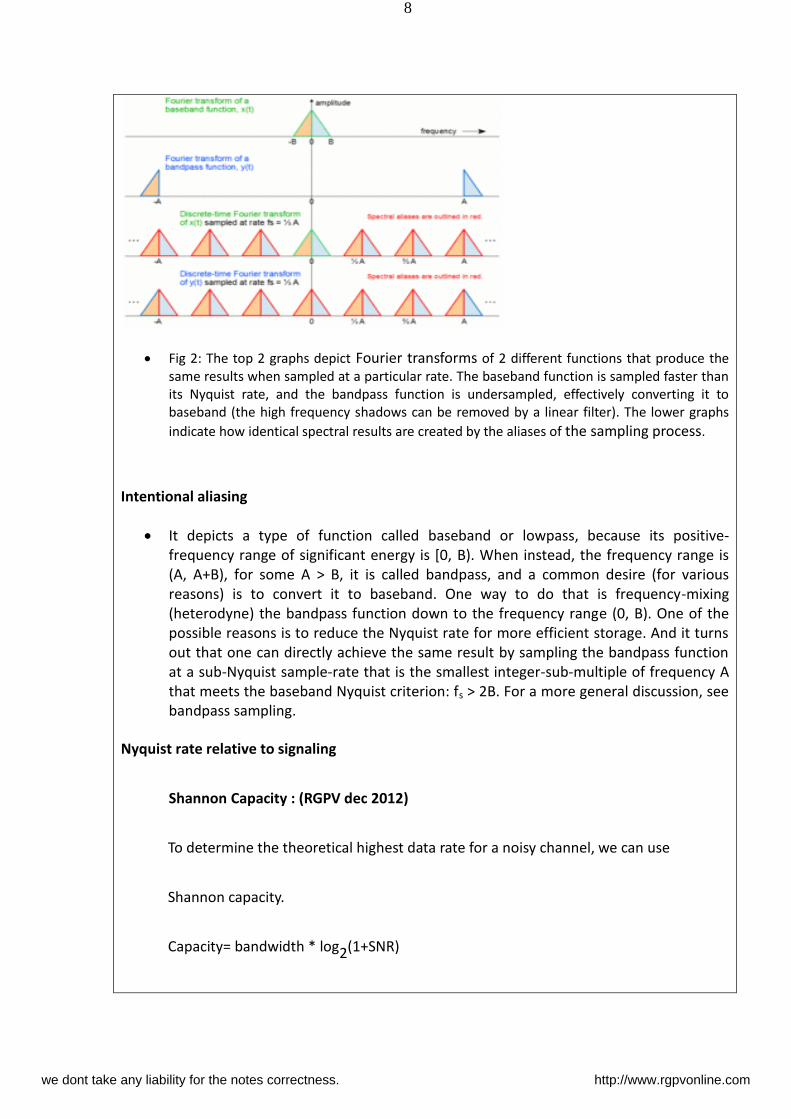
Fig 2: The top 2 graphs depict Fourier transforms of 2 different functions that produce the
same results when sampled at a particular rate. The baseband function is sampled faster than
its Nyquist rate, and the bandpass function is undersampled, effectively converting it to
baseband (the high frequency shadows can be removed by a linear filter). The lower graphs
indicate how identical spectral results are created by the aliases of the sampling process.
Intentional aliasing
It depicts a type of function called baseband or lowpass, because its positive-
frequency range of significant energy is [0, B). When instead, the frequency range is
(A, A+B), for some A > B, it is called bandpass, and a common desire (for various
reasons) is to convert it to baseband. One way to do that is frequency-mixing
(heterodyne) the bandpass function down to the frequency range (0, B). One of the
possible reasons is to reduce the Nyquist rate for more efficient storage. And it turns
out that one can directly achieve the same result by sampling the bandpass function
at a sub-Nyquist sample-rate that is the smallest integer-sub-multiple of frequency A
that meets the baseband Nyquist criterion: fs > 2B. For a more general discussion, see
bandpass sampling.
Nyquist rate relative to signaling
Shannon Capacity : (RGPV dec 2012)
To determine the theoretical highest data rate for a noisy channel, we can use
Shannon capacity.
Capacity= bandwidth * log2(1+SNR)
we dont take any liability for the notes correctness. http://www.rgpvonline.com
9
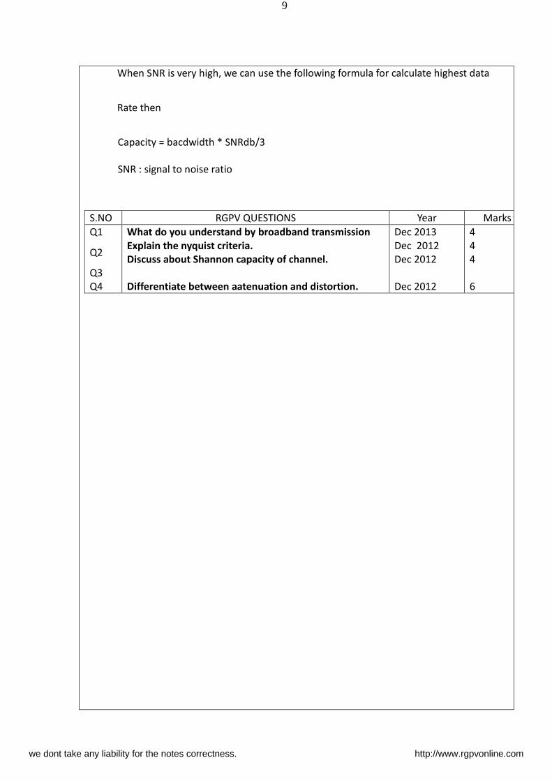
When SNR is very high, we can use the following formula for calculate highest data
Rate then
Capacity = bacdwidth * SNRdb/3
SNR : signal to noise ratio
S.NO RGPV QUESTIONS Year Marks
Q1
Q2
Q3
Q4
What do you understand by broadband transmission
Explain the nyquist criteria.
Discuss about Shannon capacity of channel.
Differentiate between aatenuation and distortion.
Dec 2013
Dec 2012
Dec 2012
Dec 2012
4
4
4
6
we dont take any liability for the notes correctness. http://www.rgpvonline.com
10
UNIT-01/LECTURE-04
Throughput: (RGPV dec 2012/2011)
1. In communication networks, such as Ethernet or packet radio, throughput or network
throughput is the rate of successful message delivery over a communication channel.
This data may be delivered over a physical or logical link, or pass through a certain
network node. The throughput is usually measured in bits per second (bit/s or bps),
and sometimes in data packets per second or data packets per time slot.
2. The system throughput or aggregate throughput is the sum of the data rates that are
delivered to all terminals in a network. Throughput is essentially synonymous to
digital bandwidth consumption; it can be analyzed mathematically by means of
queueing theory, here the load i packets per ti e u it is de oted arri al rate λ, a d the throughput in packets per time unit is denoted departure rate μ.
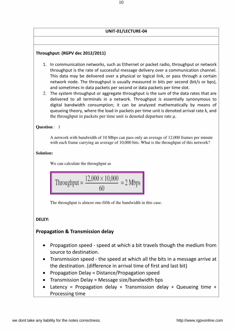
Question : 1
A network with bandwidth of 10 Mbps can pass only an average of 12,000 frames per minute
with each frame carrying an average of 10,000 bits. What is the throughput of this network?
Solution:
We can calculate the throughput as
The throughput is almost one-fifth of the bandwidth in this case.
DELEY:
Propagation & Transmission delay
Propagation speed - speed at which a bit travels though the medium from
source to destination.
Transmission speed - the speed at which all the bits in a message arrive at
the destination. (difference in arrival time of first and last bit)
Propagation Delay = Distance/Propagation speed
Transmission Delay = Message size/bandwidth bps
Latency = Propagation delay + Transmission delay + Queueing time +
Processing time
we dont take any liability for the notes correctness. http://www.rgpvonline.com
11
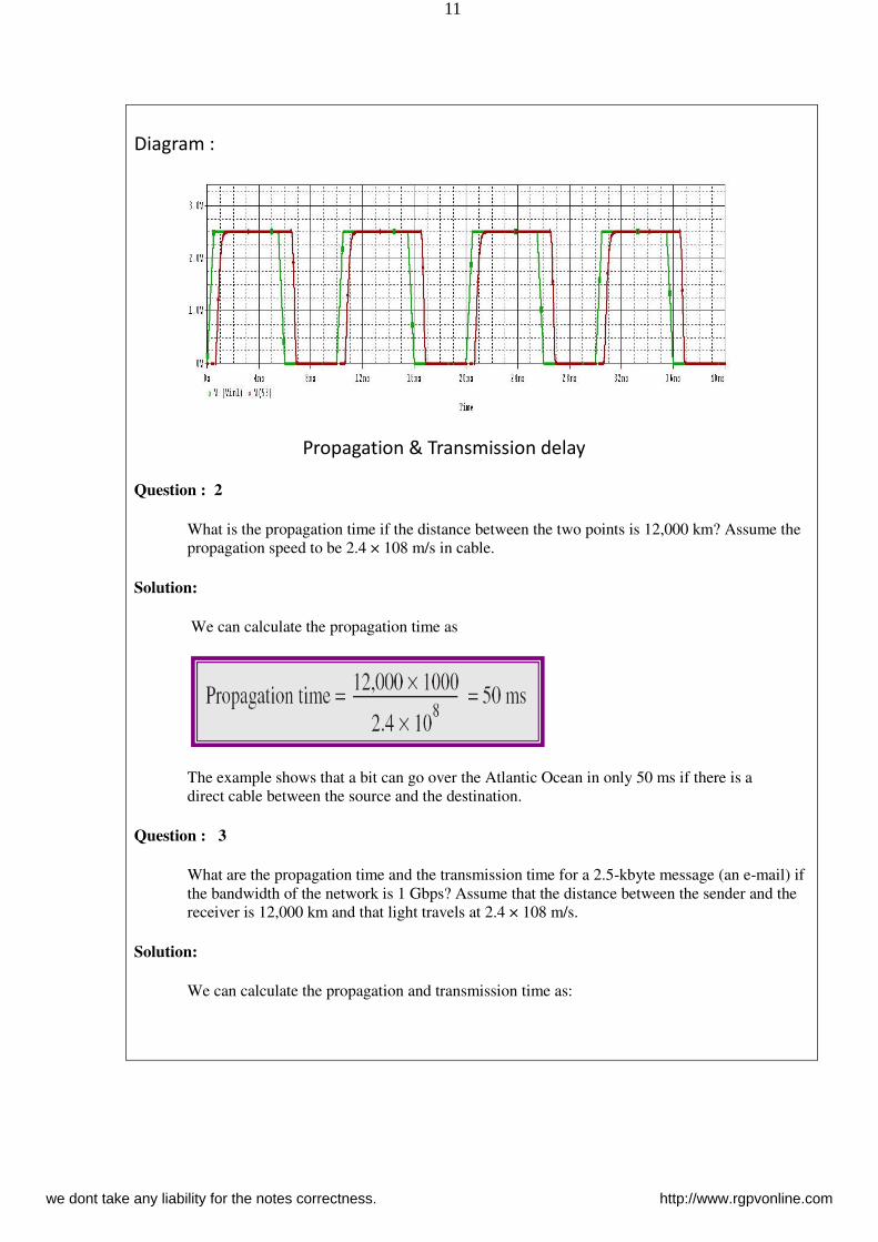
Diagram :
Propagation & Transmission delay
Question : 2
What is the propagation time if the distance between the two points is 12,000 km? Assume the
propagation speed to be 2.4 × 10⁸ m/s in cable.
Solution:
We can calculate the propagation time as
The example shows that a bit can go over the Atlantic Ocean in only 50 ms if there is a
direct cable between the source and the destination.
Question : 3
What are the propagation time and the transmission time for a 2.5-kbyte message (an e-mail) if
the bandwidth of the network is 1 Gbps? Assume that the distance between the sender and the
receiver is 12,000 km and that light travels at 2.4 × 10⁸ m/s.
Solution:
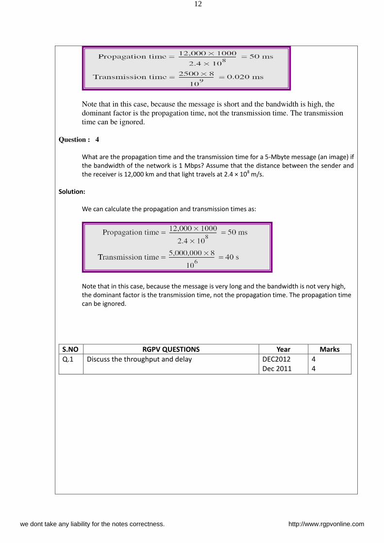
We can calculate the propagation and transmission time as:
we dont take any liability for the notes correctness. http://www.rgpvonline.com
12
Note that in this case, because the message is short and the bandwidth is high, the
dominant factor is the propagation time, not the transmission time. The transmission
time can be ignored.
Question : 4
What are the propagation time and the transmission time for a 5-Mbyte message (an image) if
the bandwidth of the network is 1 Mbps? Assume that the distance between the sender and
the receiver is 12,000 km and that light travels at 2.4 × 10⁸ m/s.
Solution:
We can calculate the propagation and transmission times as:
Note that in this case, because the message is very long and the bandwidth is not very high,
the dominant factor is the transmission time, not the propagation time. The propagation time
can be ignored.
S.NO RGPV QUESTIONS Year Marks
Q.1 Discuss the throughput and delay DEC2012
Dec 2011
4
4
we dont take any liability for the notes correctness. http://www.rgpvonline.com
13
UNIT-01/LECTURE-05
Bandwidth Delay Product : (RGPV dec 2012/2011)
1. In data communications, bandwidth-delay product refers to the product of a data
link's capacity and its end-to-end delay The result, an amount of data measured in bits
,is equivalent to the maximum amount of data on the network circuit at any given
time, i.e., data that has been transmitted but not yet acknowledged. Sometimes it is
calculated as the data link's capacity multiplied by its round trip time.
2. Ultra-high speed LANs may fall into this category, where protocol tuning is critical for
achieving peak throughput, on account of their extremely high bandwidth, even
though their delay is not great.
3. An important example of a system where the bandwidth-delay product is large is that
of GEO satellite connections, where end-to-end delivery time is very high and link
throughput may also be high. The high end-to-end delivery time makes life difficult for
stop-and-wait protocols and applications that assume rapid end-to-end response.
4. A high bandwidth-delay product is an important problem case in the design of
protocols such as TCP in respect of performance tuning, because the protocol can only
achieve optimum throughput if a sender sends a sufficiently large quantity of data
before being required to stop and wait until a confirming message is received from
the receiver, acknowledging successful receipt of that data. If the quantity of data
sent is insufficient compared with the bandwidth-delay product, then the link is not
being kept busy and the protocol is operating below peak efficiency for the link.
Protocols that hope to succeed in this respect need carefully designed self-
monitoring, self-tuning algorithms. The TCP window scale option may be used to solve
this problem caused by insufficient window size, which is limited to 65535 bytes
without scaling.
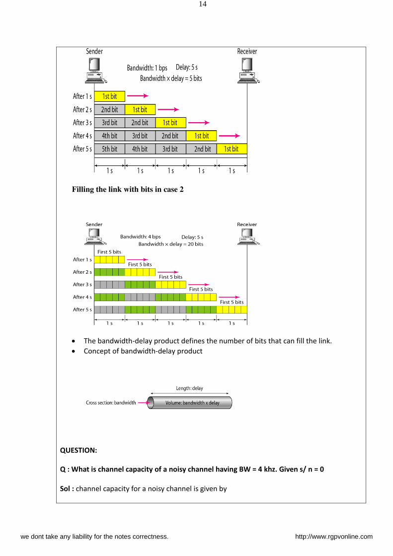
Filling the link with bits for case 1
we dont take any liability for the notes correctness. http://www.rgpvonline.com
14
Filling the link with bits in case 2
The bandwidth-delay product defines the number of bits that can fill the link.
Concept of bandwidth-delay product
QUESTION:
Q : What is channel capacity of a noisy channel having BW = 4 khz. Given s/ n = 0
Sol : channel capacity for a noisy channel is given by
we dont take any liability for the notes correctness. http://www.rgpvonline.com
15
C = BW × ( 1 + 𝑆
)
= (4 × ) × (1 + 0)
= 0
Hence channel capacity is zero. It will not transmit data.
S.NO RGPV QUESTIONS Year Marks
Q.1 Discuss the bandwidth delay product ? DEC2012
Dec 2013
4
4
UNIT-01/LECTURE-06
Jitter: (RGPV dec 2012/2013)
1. Jitter is the undesired deviation from true periodicity of an assumed periodic signal in
electronics and telecommunications, often in relation to a reference clock source.
Jitter may be observed in characteristics such as the frequency of successive pulses,
the signal amplitude, or phase of periodic signals. Jitter is a significant, and usually
undesired, factor in the design of almost all communications links.In clock recovery
applications it is called timing jitter.
2. Jitter can be quantified in the same terms as all time-varying signals, e.g., RMS, or
peak-to-peak displacement. Also like other time-varying signals, jitter can be
expressed in terms of spectral density.
3. Jitter period is the interval between two times of maximum effect (or minimum
effect) of a signal characteristic that varies regularly with time. Jitter frequency, the
more commonly quoted figure, is its inverse classifies jitter frequencies below 10 Hz
as wander and frequencies at or above 10 Hz as jitter.
4. Jitter may be caused by electromagnetic interference and crosstalk with carriers of
other signals. Jitter can cause a display monitor to flicker, affect the performance of
processors in personal computers, introduce clicks or other undesired effects in audio
signals, and loss of transmitted data between network devices. The amount of
tolerable jitter depends on the affected application.
Jitter metrics
For clock jitter, there are three commonly used metrics: absolute jitter, period jitter, and
cycle to cycle jitter.Absolute jitter is the absolute difference in the position of a clock's edge
from where it would ideally be.Period jitter is the difference between any one clock period
and the ideal/average clock period. Accordingly, it can be thought of as the discrete-time
derivative of absolute jitter. Period jitter tends to be important in synchronous circuitry like
digital state machines where the error-free operation of the circuitry is limited by the
we dont take any liability for the notes correctness. http://www.rgpvonline.com
16
shortest possible clock period, and the performance of the circuitry is limited by the average
clock period. Hence, synchronous circuitry benefits from minimizing period jitter, so that the
shortest clock period approaches the average clock period.Cycle-to-cycle jitter is the
difference in length/duration of any two adjacent clock periods. Accordingly, it can be
thought of as the discrete-time derivative of period jitter. It can be important for some types
of clock generation circuitry used in microprocessors and RAM interfaces.Since they have
different generation mechanisms, different circuit effects, and different measurement
methodology, it is useful to quantify them separately.In telecommunications, the unit used
for the above types of jitter is usually the Unit Interval which quantifies the jitter in terms of a
fraction of the ideal period of a bit. This unit is useful because it scales with clock frequency
and thus allows relatively slow interconnects such as T1 to be compared to higher-speed
internet backbone links such as OC-192. Absolute units such as picoseconds are more
common in microprocessor applications. Units of degrees and radians are also used.
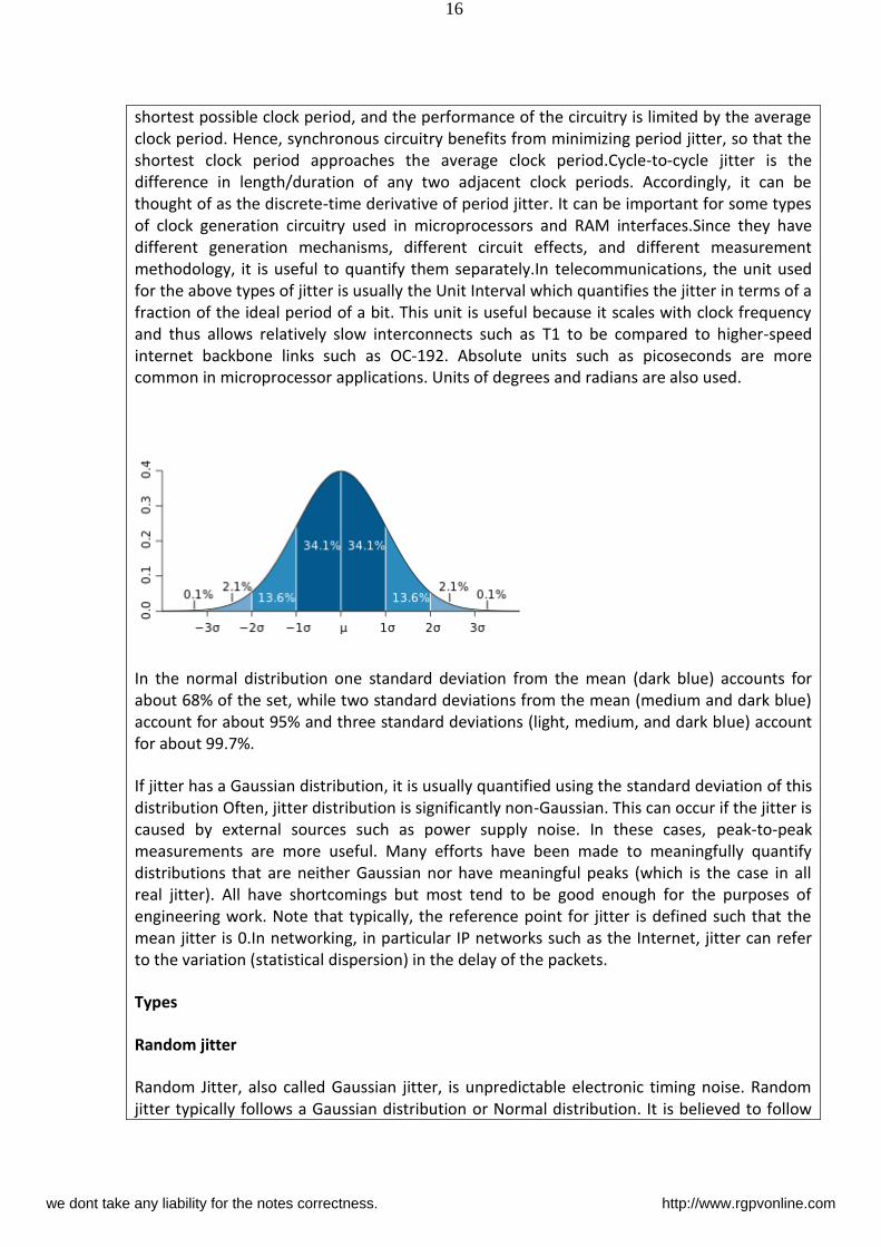
In the normal distribution one standard deviation from the mean (dark blue) accounts for
about 68% of the set, while two standard deviations from the mean (medium and dark blue)
account for about 95% and three standard deviations (light, medium, and dark blue) account
for about 99.7%.
If jitter has a Gaussian distribution, it is usually quantified using the standard deviation of this
distribution Often, jitter distribution is significantly non-Gaussian. This can occur if the jitter is
caused by external sources such as power supply noise. In these cases, peak-to-peak
measurements are more useful. Many efforts have been made to meaningfully quantify
distributions that are neither Gaussian nor have meaningful peaks (which is the case in all
real jitter). All have shortcomings but most tend to be good enough for the purposes of
engineering work. Note that typically, the reference point for jitter is defined such that the
mean jitter is 0.In networking, in particular IP networks such as the Internet, jitter can refer
to the variation (statistical dispersion) in the delay of the packets.
Types
Random jitter
Random Jitter, also called Gaussian jitter, is unpredictable electronic timing noise. Random
jitter typically follows a Gaussian distribution or Normal distribution. It is believed to follow
we dont take any liability for the notes correctness. http://www.rgpvonline.com
17
this pattern because most noise or jitter in an electrical circuit is caused by thermal noise,
which has a Gaussian distribution. Another reason for random jitter to have a distribution like
this is due to the central limit theorem. The central limit theorem states that composite
effect of many uncorrelated noise sources, regardless of the distributions, approaches a
Gaussian distribution. One of the main differences between random and deterministic jitter is
that deterministic jitter is bounded and random jitter is unbounded.
Deterministic jitter
Deterministic jitter is a type of clock timing jitter or data signal jitter that is predictable and
reproducible. The peak-to-peak value of this jitter is bounded, and the bounds can easily be
observed and predicted. Deterministic jitter can either be correlated to the data stream
(data-dependent jitter) or uncorrelated to the data stream (bounded uncorrelated jitter).
Examples of data-dependent jitter are duty-cycle dependent jitter (also known as duty-cycle
distortion) and intersymbol interference. Deterministic jitter has a known non-Gaussian
probability distribution.
Q : A system sends a signal that can assume 8 different voltage levels. It sends 400 of these
signals per second. What is baud rate ?
Sol : Baud rate is defined as the number of signals transmitted per second. Since 400 symbols
are transmitted per second.
Baud rate = 400 symbols / sec
S.NO RGPV QUESTIONS Year Marks
Q.1 Explain the jitter and types of jitter Dec
2012
Dec
2013
7
we dont take any liability for the notes correctness. http://www.rgpvonline.com

18
UNIT-01/LECTURE-07
we dont take any liability for the notes correctness. http://www.rgpvonline.com

19
UNIT-01/LECTURE-08
we dont take any liability for the notes correctness. http://www.rgpvonline.com

20
UNIT-01/LECTURE-09
we dont take any liability for the notes correctness. http://www.rgpvonline.com
21
UNIT-02/LECTURE-10
An FM wave consists of infinite number of side bands so that the bandwidth is theoretically
infinite. But, in practice, the FM wave is effectively limited to a finite number of side band
frequencies compatible with a small amount of distortion.
Carson’s Rule:-
An empirical formula for the bandwidth of a single tone wideband FM is given by carson s
rule. According to this rule, the Fm bandwidth is given by
= ∆𝜔 + 𝑚
= ∆𝜔 + 𝑚∆𝜔 Since ∆𝜔𝑤𝑚 = 𝑓
So 𝑤𝑚∆𝜔 = 𝑚𝑓
= ∆𝜔 + 𝑚𝑓 radians
Or = ∆ + 𝑚𝑓 Hz
(i) When ∆𝜔 𝑚 (narrowband FM) i.e. 𝑓
Then = 𝑚
Which is equivalent to AM
(ii) When
∆𝜔 𝑚 (wideband FM) i.e. 𝑓
we dont take any liability for the notes correctness. http://www.rgpvonline.com
22
Then = ∆𝜔
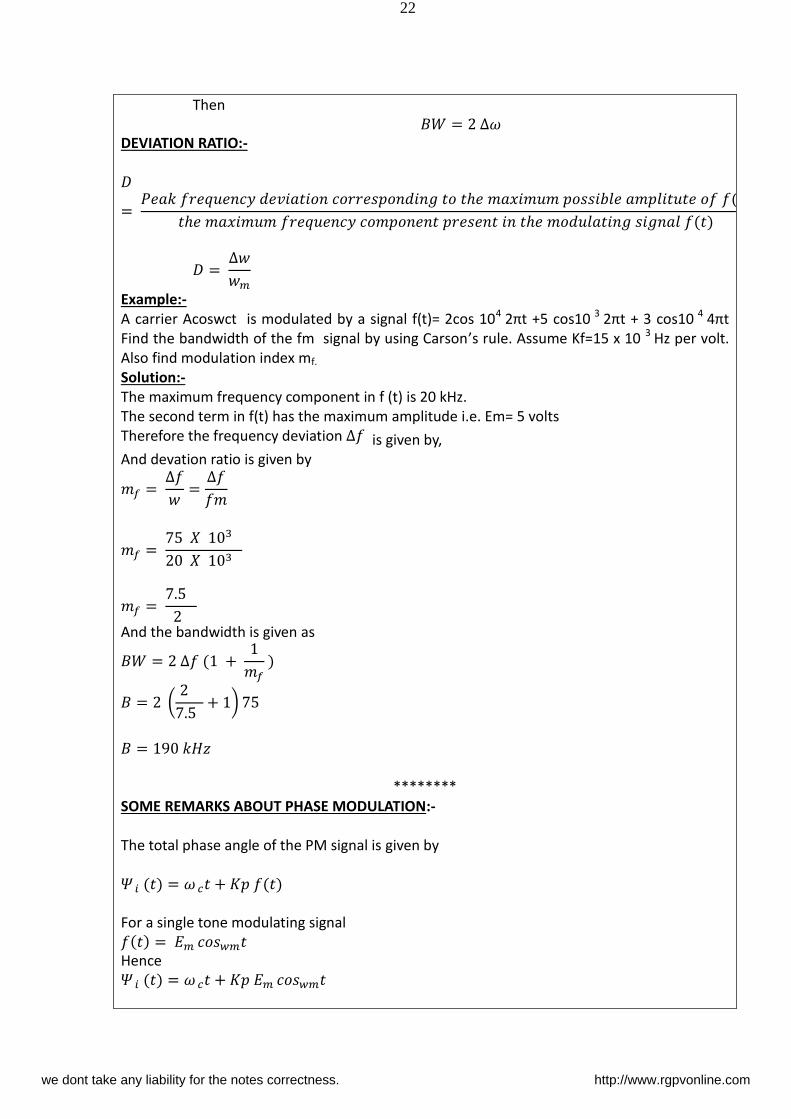
DEVIATION RATIO:-
= 𝑃 𝑖 𝑖 𝑖 ℎ 𝑖 𝑖 𝑖 ℎ 𝑖 𝑖 ℎ 𝑖 𝑖 = ∆𝑚
Example:-
A carrier Acoswct is modulated by a signal f(t)= 2cos 104 πt + cos 3 πt + cos 4 πt
Find the bandwidth of the fm signal by using Carson s rule. Assume Kf=15 x 10 3
Hz per volt.
Also find modulation index mf.
Solution:-
The maximum frequency component in f (t) is 20 kHz.
The second term in f(t) has the maximum amplitude i.e. Em= 5 volts
Therefore the frequency deviation ∆ is given by,
And devation ratio is given by
𝑓 = ∆ = ∆
𝑓 =
𝑓 = .
And the bandwidth is given as = ∆ + 𝑓 = ( . + )
= 𝐻
********
SOME REMARKS ABOUT PHASE MODULATION:-
The total phase angle of the PM signal is given by
𝛹 𝑖 = 𝜔 + 𝐾
For a single tone modulating signal = 𝑚 𝑤𝑚
Hence 𝛹 𝑖 = 𝜔 + 𝐾 𝑚 𝑤𝑚
we dont take any liability for the notes correctness. http://www.rgpvonline.com
23
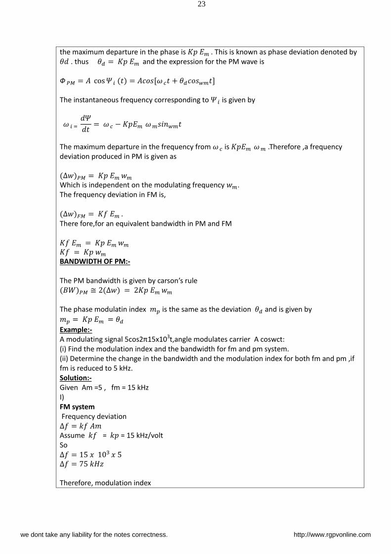
the maximum departure in the phase is 𝐾 𝑚 . This is known as phase deviation denoted by 𝜃 . thus 𝜃 = 𝐾 𝑚 and the expression for the PM wave is
Ф 𝑃 = cos 𝛹 𝑖 = [𝜔 + 𝜃 𝑤𝑚 ]
The instantaneous frequency corresponding to 𝛹 𝑖 is given by
𝜔 𝑖 = 𝛹 = 𝜔 − 𝐾 𝑚 𝜔 𝑚 𝑖 𝑤𝑚
The maximum departure in the frequency from 𝜔 is 𝐾 𝑚 𝜔 𝑚 .Therefore ,a frequency
deviation produced in PM is given as
∆ 𝑃 = 𝐾 𝑚 𝑚
Which is independent on the modulating frequency 𝑚.
The frequency deviation in FM is,
∆ 𝐹 = 𝐾 𝑚 . There fore,for an equivalent bandwidth in PM and FM
𝐾 𝑚 = 𝐾 𝑚 𝑚 𝐾 = 𝐾 𝑚
BANDWIDTH OF PM:-
The PM bandwidth is given by carson s rule 𝑃 ≅ ∆ = 𝐾 𝑚 𝑚
The phase modulatin index 𝑝 is the same as the deviation 𝜃 and is given by 𝑝 = 𝐾 𝑚 = 𝜃
Example:-
A odulati g sig al cos π15x103t,angle modulates carrier A coswct:
(i) Find the modulation index and the bandwidth for fm and pm system.
(ii) Determine the change in the bandwidth and the modulation index for both fm and pm ,if
fm is reduced to 5 kHz.
Solution:-
Given Am =5 , fm = 15 kHz
I)
FM system
Frequency deviation ∆ =
Assume = = 15 kHz/volt
So ∆ = ∆ = 𝐻
Therefore, modulation index
we dont take any liability for the notes correctness. http://www.rgpvonline.com
24
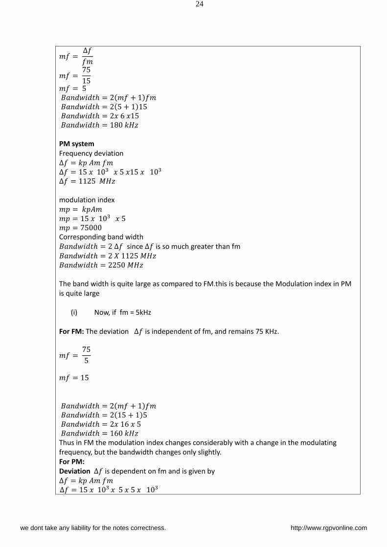
= ∆ = =
𝑖 ℎ = +
𝑖 ℎ = +
𝑖 ℎ =
𝑖 ℎ = 𝐻
PM system
Frequency deviation ∆ = ∆ = ∆ = 𝑀𝐻
modulation index = = =
Corresponding band width 𝑖 ℎ = ∆ since ∆ is so much greater than fm 𝑖 ℎ = 𝑀𝐻 𝑖 ℎ = 𝑀𝐻
The band width is quite large as compared to FM.this is because the Modulation index in PM
is quite large
(i) Now, if fm = 5kHz
For FM: The deviation ∆ is independent of fm, and remains 75 KHz.
=
=
𝑖 ℎ = +
𝑖 ℎ = +
𝑖 ℎ =
𝑖 ℎ = 𝐻
Thus in FM the modulation index changes considerably with a change in the modulating
frequency, but the bandwidth changes only slightly.
For PM:
Deviation ∆ is dependent on fm and is given by ∆ = ∆ = we dont take any liability for the notes correctness. http://www.rgpvonline.com
25
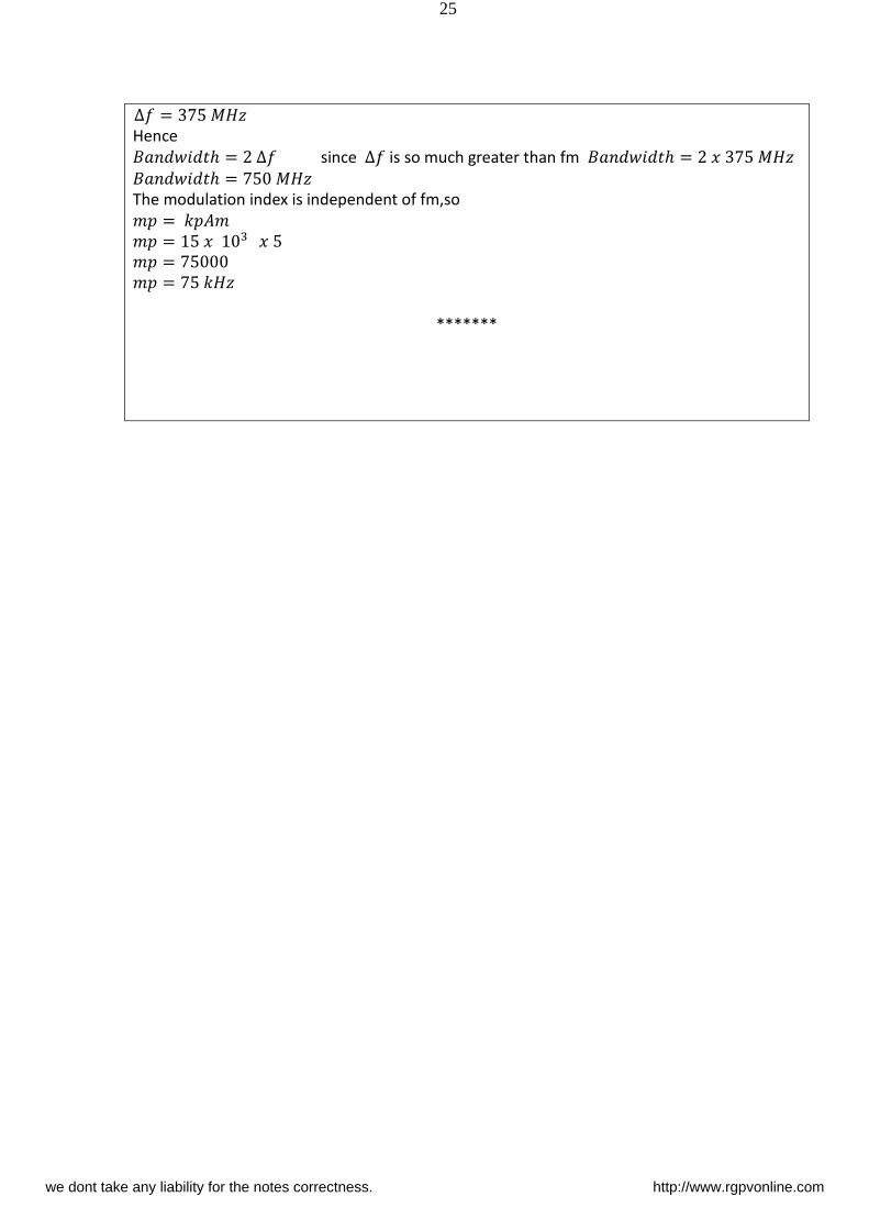
∆ = 𝑀𝐻
Hence 𝑖 ℎ = ∆ since ∆ is so much greater than fm 𝑖 ℎ = 𝑀𝐻 𝑖 ℎ = 𝑀𝐻
The modulation index is independent of fm,so = = = = 𝐻
*******
we dont take any liability for the notes correctness. http://www.rgpvonline.com