Embed Size (px)
Citation preview

1
TESTS ON REINFORCED CONCRETE COLUMNS WITH WING WALLS FOR HYPER-EARTHQUAKE RESISTANT SYSTEM
Toshimi Kabeyasawa1, Toshikazu Kabeyasawa2
Yousok Kim3, Toshinori Kabeyasawa4, and Kunkuk Bae5
ABSTRACT Four specimens were tested representing reinforced concrete column with a wing wall to investigate seismic performance of members with an irregular section. The specimens were one-half scale columns combined with a wing wall only on one side in the loading direction. The section and reinforcement details were planned following the previous tests on columns with wing walls on both sides. The effects of asymmetric horizontal section, reinforcement details and varying axial force on seismic performance were investigated. The ultimate strengths of the members were identified with the observed failure modes. The measured flexural and shear strengths were compared with the calculated strengths based on the conventional design formula as well as new formula in practice proposed by the authors with the results of the first test series. Application of these members is also shown for design of “hyper-earthquake resistant system,” by which damages could be minor insensitive to possible extreme motions.
INTRODUCTION Full-scale shake table tests on school building were conducted at E-Defense, the world largest three-dimensional shake table, from September to November 2006 [Kabeyasawa 2007a,b]. A dynamic progressive collapse of the bare frame specimen occurred associated with shear and axial failure of short columns in case of fixed foundation, while an obvious input loss was observed in case of swaying foundation. Base on the test result, we have proposed "hyper-earthquake resistant system," which is based on a simple fail-safe design concept against extreme motions exceeding the design level, consisting of relatively strong superstructure and sway-slip foundation. The slip behavior would occur only under very high ground acceleration, so that the response of the superstructure could be controlled as minor as insensitive to the level and characteristics of possible extreme motion. Use of columns with wing walls is a simple but cost-effective design option to provide a superstructure with relatively higher capacity, up to required in the hyper-earthquake resistant system. The field investigations on the structural damages induced from past earthquakes and laboratory tests indicated that reinforced concrete columns with wing-walls had relatively good seismic performance as earthquake-resistant members increasing column stiffness and strength in reinforced concrete buildings. In Japan, however, columns with wing-walls have not been designed and used very much as earthquake resistant elements. Instead, they have been often separated from structural members by installing seismic slit between the column and the wall. Since columns with wing-walls show 1 Earthquake Research Institute, University of Tokyo; Tokyo, Japan 2 Faculty of Engineering, University of Tokyo; Tokyo, Japan 3 Earthquake Research Institute, University of Tokyo; Tokyo, Japan 4 Wada-Giken Corporation, Osaka, formally with Earthquake Research Institute, University of Tokyo; Tokyo, Japan 5 Earthquake Research Institute, University of Tokyo; Tokyo, Japan

2
different seismic behavior from shear walls or independent columns, the evaluation method of its strength and ductility has not been clearly defined in the guidelines for design practice, which makes it difficult to design columns with wing-walls. However, the wing-wall attached to column undoubtedly increases the lateral strength of column, therefore, installing seismic slit between column and wing-wall might be inefficient in many cases of low-rise buildings, which could have been designed as strength-based-design. Conventional evaluation methods for columns with wing-walls may be found in Seismic Evaluation Standard for RC buildings by The Japan Building Disaster Prevention Association [JBDPA, 2001] and also in Guidelines for Standard Requirements on Building Structures by The Building Center of Japan [BCJ, 2007]. However, the conventional evaluation methods for ultimate strength and ductility, or member ranks are not rational in mechanical point of view. In addition, these methods are formulated by assuming columns with both-side wing-walls, so the design equations are not basically applicable to columns with one-sided wing-wall. In this study, four specimens representing reinforced concrete column with a wing wall were tested to investigate seismic performance of the member with irregular section. The specimens were one-half scale columns combined with a wing wall only on one side in the loading direction. The section and reinforcement details were planned following the previous tests on columns with wing walls on both sides[Kabeyasawa 2008 and Tojo 2008]. The effects of asymmetric horizontal section, reinforcement details and varying axial force on seismic performance were investigated. The ultimate strengths of the members were identified with the observed failure modes. The measured flexural and shear strengths were compared with the calculated strengths based on the conventional design formula as well as new formula, which had been proposed by the authors [Kabeyasawa 2007c] with the results of the first test series.
TEST ON COLUMNS WITH A WING-WALL Test Specimens The characteristics of specimens are listed in Table 1. The scale of specimens is half or two-thirds to typical sections of full-scale medium-rise buildings in Japan. The section and reinforcement details of each specimen described in Table 1 were planned following the previous tests [Kabeyasawa 2008 and Tojo 2008] on column with wing walls on its both sides. The length of wing-wall in SWT-L and SWT-LW is equal to the sum of lengths of both-side wing-wall tested in 2007 [Kabeyasawa 2008 and Tojo 2008], and the length of wing-wall in SWT-SC and SWT-SV is half to that of SWT-L and SWT-LW. The section of SWT-LW is identical to SWT-L, but the reinforcement ratio of SWT-LW is twice to that of SWT-L except longitudinal reinforcement at the end of wing wall (Fig.1) that is identical between two specimens. On the other hand, SWT-SC and SWT-SV have the same reinforcement ratio to that of SWT-L, but its longitudinal reinforcement at the end of wing-wall is 6-D10 which is smaller than that of SWT-L (8-D10) and same to that of both-sided wing-wall specimens tested in 2007. SWT-SV and SWT-SC have identical section details, but SWT-SV was subjected to varying axial load while SWT-SC was tested under constant axial load. Material properties of reinforcement are summarized in Table 2. The nominal strength of concrete was 24MPa, while 31.6 to 33.3MPa from the material test as shown in Table 1.

3
(a) SWT-L (b) SWT-LW (c) SWT-SC, SV Fig. 1. Specimen details
Table 1. List of specimens
Column (mm) Wing wall (mm) Axial Force (kN)
M/Q (mm) Specimen
Concrete Strength (N/mm2) Section Main
bars Hoop LengthWidth Vertical reinforcement
Main bars at section end
Horizontal reinforcement + - + -
SWT-L 33.3 2-D6@50 (0.32%)
2-D6@200 (0.32%)
2-D6@200 (0.32%)
SWT-LW 33.3 4-D6@50 (0.64%)
800 2-D6@100 (0.64%)
8-D10 2-D6@100 (0.64%)
SWT-SC 31.6
800 1000
SWT-SV 31.6
400 *
400
16-D16 (2.0%)
2-D6@50 (0.32%) 400
100
2-D6@200 (0.32%) 6-D10 2-D6@200
(0.32%) 400+2Q900 1100
Table 2. Material properties of steel
Mark D6 D10 D16 Yield Strength (N/mm2) 340 363 372
Elastic Young’s Modulus (104N/mm2) 17.31 18.58 18.86 Tensile Strength (N/mm2) 453 512 558
Loading System Figure 2 shows the experimental apparatus installed at Earthquake Research Institute, University of Tokyo, which consists one horizontal and two vertical jacks with maximum loading capacity of 1000kN. For SWT-L, SWT-LW and SWT-SC, the total constant axial load N applied at the column center is 800kN corresponding to the axial load ratio of 0.2 that is N / (2Ac*Fc) = 0.2, where, Ac is column section area and Fc is compressive concrete strength (24Mpa). And SWT-SV was subjected to varying axial load calculated from Eq.(1), which simulated the actions in a prototype six-story building. As lateral load is applied to the specimen through the horizontal jack, axial load is computed from Eq.(2), (3) and applied simultaneously so that the shear sapn (M/Q) from the bottom of column center to contraflexural point could be kept constant. )(2400 kNQN += (1)
Reinforcing details at the wing wall end

4
QQMNN ⋅+−−⋅
+=
13501850)2000/(
135018501350
1 (2)
12 NNN −= (3) where N1, N2 and Q are vertical and lateral load, respectively. Lateral loading is controlled based on displacement and reversed at the peak drift ratios of ±1/400, ±1/300, ±1/200, ±1/150, ±1/100, ±1/75, ±1/50, ±1/37.5. ±1/25. For the specimens subjected to constant axial load (SWT-L, SWT-LW and SWT-SC), shear span (moment-to-shear ratio, M/Q) is kept to be 1000mm (clear height of column is 1400mm). Therefore, the shear span to depth ratio (M/Qd, d is effective depth of column with wing-wall) of SWT-L and SWT-LW is 0.83 and 1.25 in case of SWT-SC. On the other hand, shear span of SWT-SV subjected to varying axial load was kept to be 900mm (M/Qd =1.13) in positive direction (column compression) and 1100mm (M/Qd =1.38) in negative direction (column tension) (Table 1). The selection of these shear span to depth ratio was intended not to allow flexural yield at the top of the specimen. After specimen collapsed, the compressive axial force was applied to the specimen for the purpose of investigating residual axial load carrying capacity.
Fig. 2. Loading system
DESIGN METHODS IN PRACTICE FOR COLUMNS WITH WING-WALLS
Conventional Design Equations for Columns with Wing-Walls The following equations (4) and (5) for flexure and shear in the guidelines [JBDPA.2001 and BCJ.2007] are based on the idea of the equivalent wall thickness method, where the column with wing-wall section are replaced with the equivalent uniform thickness wall with the same sectional area (Table 4). The problems of these conventional methods may be summarized as: At the end of the wing wall section on which excessive stress is concentrated, the thickness of equivalent section is always overestimated compared to that of actual thickness of wing wall. Since the ends of the wing walls are not confined generally by the transverse reinforcement, it becomes overestimation to substitute into the equivalent wall from e.g. the wall with boundary columns. It is also apparently overestimation to calculate an equivalent transverse reinforcement ratio as the sum of the ratios of column hoops and wall web reinforcement from Equation (6).

5
⎪⎭
⎪⎬⎫
⎪⎩
⎪⎨⎧
⎟⎟⎠
⎞⎜⎜⎝
⎛+−+++=
2
1215.0)9.0(N
aDFbNNDDaM yt
ceytu
σβσβ
(4)
Njbp
QdMFpQ eewywe
e
ctsu 1.085.0
12.0)18(053.0 23.0
+⎭⎬⎫
⎩⎨⎧
++
+= σ
(5)
⎟⎟⎠
⎞⎜⎜⎝
⎛+⎟⎟
⎠
⎞⎜⎜⎝
⎛=
es
ewwe b
tpbbpp
(6)
Table 4. Equivalent sections for strength evaluation of columns with wing-walls
The wing wall length on the tensile side is disregarded expediently in the equation by JBDPA as shown in Table 4 so that the overestimation due to the equivalent area replacement could be canceled out. However, if the wing wall lengths between left and right side are different or if the wing wall is attached on only one side, the method is not applicable and undefined. The calculation methods for the wing wall length (de) and the wall thickness (be) are different between JBDPA.2001 and BCJ 2007 also shown in Table 4, although the background is not clear. In addition, simple accumulation of the ratios of the hoops and the web reinforcement by Eq.(6) is apparently invalid and irrational. Proposed Design Equation in Practice – Cumulative Method with Divided Sections Considering those problems in the conventional evaluation methods described as above, a modified design formula for columns with wing walls has been proposed(Kabeyasawa, 2007), referred as “Cumulative Method with Divided Sections.” This proposed method evaluates the shear strength of column with wing wall by accumulating individual shear strength of wall and column based on conventional practical design equations for shear(Eqs. (7), (8), (9)), where the sections are divided into the direction of the wall length as shown in Fig. 3. NQQQ sucsuwsu 1.0++= (7)
Guidelines [JBDPA, 2001] [BCJ, 2007]
Positive loading
(→)
tension compression
tension compression
Negative loading
(←)
compression tension
tension compression
de Distance from the center of column tensile bar to
edge of compressive zone Distance from the center of tensile bar
group to edge of compressive zone
be (column section+compressive wing wall section)
/(column depth+compressive wing wall length) Whole section area / whole depth

6
wwwhywh
w
ctwesuw jtp
QdM
FpQ
⎪⎪⎭
⎪⎪⎬
⎫
⎪⎪⎩
⎪⎪⎨
⎧
++
+= σ85.012.0
)18(053.0 23.0 (8)
where wwtwtwe dtap /= , twa : area of column tensile bars and wing wall vertical reinforcements within 2 layers, QM / : shear span ( 2/5.0 ≤≤ wQdM ), )(95.0 21 llDdw ++= , wwwhwh stap /= ,
wwwhwh stap /= , whyσ : yield strength of wing wall reinforcement.
cececwycwe
ce
ctcesuc jbp
QdM
FpQ
⎪⎪⎭
⎪⎪⎬
⎫
⎪⎪⎩
⎪⎪⎨
⎧
++
+= σ85.012.0
)18(053.0 23.0 (9)
where })/{( cewtctce dtBap −= , tca : area of column tensile reinforcement, QM / : shear span ( 3/1 ≤≤ ceQdM ), Ddce 95.0= , )/()( sbstpap cewwhwcwe −= , )/( sbap cewcwe = , wce tBb −= , wa : hoop area of column, s : hoop spacing, whp : horizontal reinforcement ratio of wing wall, cwyσ : yield strength of hoop, B : column width, wt : wing wall width, cec dj ⋅= 8/7
Fig. 3. Dividing the column section with wing wall
TEST RESULTS ON COLUMNS WITH ONE-SIDED WING-WALL Failure Process Flexural bending and shear cracks of all specimens occurred and progressed from the wing-wall at the loading cycle of +1/400rad. In the negative direction when the wing wall is in compression, the shear cracks were initially developed in the wing-wall and top of column at the loading cycle of -1/400rad. In case of SWT-SV subjected to varying axial load, flexural bending cracks were much wider compared to the other specimens, which might be due to low axial load level. Figure 4 shows the final failure states of each specimen. The failure modes of the specimens are described separately on column and wing-wall in each direction because they are different. The failure mode is determined from yielding sequence of reinforcing bars based on measured strains, such as longitudinal or transverse re-bars of column and horizontal or longitudinal re-bars of the wing wall. The failure mode, ultimate shear strength and residual axial load carrying capacity of each specimen are described as follows: SWT-L: The failure mode of the wing-wall in the positive direction (column in compression) may be defined as flexural bending failure, because the longitudinal reinforcement at the end of
l1 D l2
tw B
Qsuc
Qsu
bce=B-tw L

7
wing wall section yielded first. In the negative direction (wing wall in compression), the wing wall failed in shear. Crushing occurred in the loading cycle of -1/200rad at the bottom of the wing wall. The longitudinal re-bars of the columns yielded near at +1/100rad, though its failure mode was not clear, because the hoop strains at the top of column could not be identified. During the loading cycle of -1/100rad, diagonal shear tension failure occurred over the entire specimen at -8.55mm, slightly exceeding -1/200rad, and the constant axial load (800kN) could not be sustained after the shear failure. SWT-LW: The failure mode of the wing wall in the positive direction is identical to that of SWT-L. While the horizontal reinforcement of the wing wall yielded first in the negative direction (shear failure), yielding of longitudinal re-bars of the column followed by crushing of the wing wall at the cycle of –1/200rad. induced crucial damage and switched the failure mode of the specimen from shear to flexural failure. Because the specimen did not collapse until the loading cycle of +1/25rad, loading was continued till +1/12.5rad. After crushing occurred at the bottom of column about +1/21rad (65mm), diagonal shear tension failure occurred at column and the displacement increased by sliding along the failure surface though it could sustain the axial load. After the cyclic lateral loading was finished, the specimen was subjected to axial loading and attained up to 1000kN (axial load ratio for column section = 0.3). SWT-SC: Damage process and failure modes were similar to those of SWT-LW, which were flexural failure in the positive direction and shear failure in the negative direction. After crushing occurred in wing-wall at the -1/150rad, yield of longitudinal reinforcement of column changed the failure mode from shear to flexural failure in negative direction. The column failed in shear at the loading cycle of -1/37.5rad corresponding to -34.66mm. In spite of shear failure of column, the specimen could sustain axial force in stable, but at the drift ratio of 1/25rad, the specimen lost its axial load carrying capacity and loading was terminated. SWT-SV: In the positive direction, flexural failure mode was observed while shear failure in the negative direction, which was the same as those observed in other specimens. Although compressive failure of wing wall (crushing) occurred at relatively large drift ratio (1/75rad.) compared to the other specimens, the ultimate failure mode was changed from shear to flexural failure characterized by yielding of the longitudinal re-bars of the column. Crushing at the column was observed at the drift ratio of +1/37.5rad. After the final loading cycle of +1/12.5rad, the specimen was subjected to axial loading and could sustain up to about 1500kN, which corresponded to the axial load ratio of 0.37. Hysteretic Relations The hysteretic relations of each specimen are shown in Fig. 5, where calculated flexural and shear strength are also shown with horizontal lines. three different equations for the shear strength described as above are used including JBDPA(2001), BCJ(2007), and Cumulative Method with Divided Sections (Kabeyasawa 2007). Higher calculated strengths being out of scale were not illustrated. The strengths of SWT-SV subjected to varying axial load were calculated using the experimental axial load at the peaks. In the positive direction (column compression), all the specimens failed in flexure due to the yield of longitudinal reinforcements at the end of the wing wall section. Ductile behavior with slight strength deterioration was observed after the post-peak region. On the other hand, different

8
failure modes were observed in the negative direction where the column was in tension and the wing wall in compression. Drastic deterioration of the lateral resistance and the loss of the axial load carrying capacity was observed in the specimen SWT-L showing typical shear failure mode. Onset of strength deterioration in the specimen SWT-LW and SWT-SC was initiated soon after attaining the maximum strength followed by crushing of concrete at the edge of the wing wall. The specimen SWT-SV subjected to varying axial load showed higher deformability and lower strength and stiffness than those of SWT-SC subjected to the constant axial load. Observed and Calculated Ultimate Strengths Figure 5 compares the observed ultimate strengths of the specimens with the calculated strengths based on both conventional and proposed formula, where the strength of SWT-SV subjected to varying axial load was calculated using the observed axial load at peak. As is described in the figure, in the positive direction where the column is in compression, all the specimens showed flexural failure mode characterized by yielding of longitudinal reinforcement at the end of the wing wall section. On the other hand, both shear and flexural failure indicating concrete crushing or yielding of the column main bars were observed in the negative direction. When the ultimate strength was attained, the failure mode of all the specimens could be categorized into shear failure. From these results, observed maximum strengths in positive direction may be compared with the calculated flexural strengths, and those in negative direction may be compared with the calculated shear strengths. The white and black markers shown in Fig. 5 indicate shear and flexural failure mode of specimens, respectively, from which the calculated shear strengths of the specimens categorized into the shear failure mode (white markers) are compared with the observed lateral strengths. While the shear strengths calculated from conventional evaluation methods by JBDPA Seismic Evaluation Standard [JBDPA, 2001] and BCJ Guidelines [BCJ, 2007] are almost the same and overestimated the observed shear strength by 1.15~1.3 times, while the shear strength calculated from the proposed formula underestimated the observed ones (i.e., 20% below that of SWT-SV and 30% below those of the other specimens). These results show that the conventional equations, where the wing wall in tension is disregarded so that the overestimation could be canceled out in the estimation, is not conservative in case of the columns with one-sided wing wall. On the other hand, the proposed formula provides conservative estimates by approximately 20~30% of safety margin, which is a little smaller to that of Arakawa’s equation obtained for the past tests on independent columns and shear walls. In cases of SWT-L and SWT-SC between which the wing wall lengths were different, the shear strength of SWT-L calculated from the conventional equations is much higher than that of SWT-SC compared to the test results, which means that if the wing wall is longer, the higher shear strength is calculated from the conventional equations. On the other hand, the proposed formula could estimate the shear strength with constant safety margin regardless of the wing wall length. The different reinforcement steel ratio between SWT-L and SWT-LW did not affect the ratio of observed shear strengths to calculated ones from both conventional and proposed equations, which means that all the formulas could evaluate the effect of shear reinforcement. The lateral strengths of the specimens that exhibited flexural failure mode (black marks) are compared with the calculated flexural strengths in Fig. 6. The flexural strengths of all the specimens calculated from Eq. (4) underestimated the experimental results because the

9
longitudinal reinforcements at the end of wing-wall section are not being considered. On the other hand, the flexural strengths calculated by the equation of BCJ 2007 based on the plastic theory considering the whole cross section and reinforcements showed good agreement with the test results.
Fig. 4. Hysteretic relations and collapsed specimens
- 80 - 60 - 40 - 20 0 20 40 60 80- 1000
- 800
- 600
- 400
- 200
0
200
400
600
800
1000
Displacement (mm)
Shear force (kN)
SWT- L Shear force VS. Displacement
•
• ← Crack
•
•Shear failure → •
Maximum Strength (+) (492kN,14.29mm)
Crack
Maximum Strength (- ) (- 768kN - 7.03mm) wall crushing
- 80 - 60 - 40 - 20 0 20 40 60 80- 1000
-800
-600
-400
-200
0
200
400
600
800
1000
Displacement (mm)
Shear force (kN)
SWT- LW Shear force VS. Displacement
•
• ← Crack
•
•
Maximum Strength (+) (554kN,27.08mm)
Maximum Strength (- ) (- 875kN - 7.08mm)
Crack
- 80 - 60 - 40 - 20 0 20 40 60 80- 1000
-800
-600
-400
-200
0
200
400
600
800
1000
Displacement (mm)
Shear force (kN)
SWT- SC Shear force VS. Displacement
•
•Shear failure → •
•
•
Maximum Strength (+) (441kN,19.89mm)
Maximum Strength (- ) (- 576kN - 8.00mm) wall crushing
Crack
Crack
- 80 - 60 - 40 - 20 0 20 40 60 80- 1000
-800
-600
-400
-200
0
200
400
600
800
1000
Displacement (mm)
Shear force (kN)
SWT- SV Shear force VS. Displacement
Crack → •
• ← Crack
•
•
Maximum Strength (+) (401kN,19.06mm)
Maximum Strength (- ) (- 346kN - 15.93mm)

10
Fig. 5. Comparison of observed and calculated shear strengths
Fig. 6. Comparison of calculated and observed flexural strengths
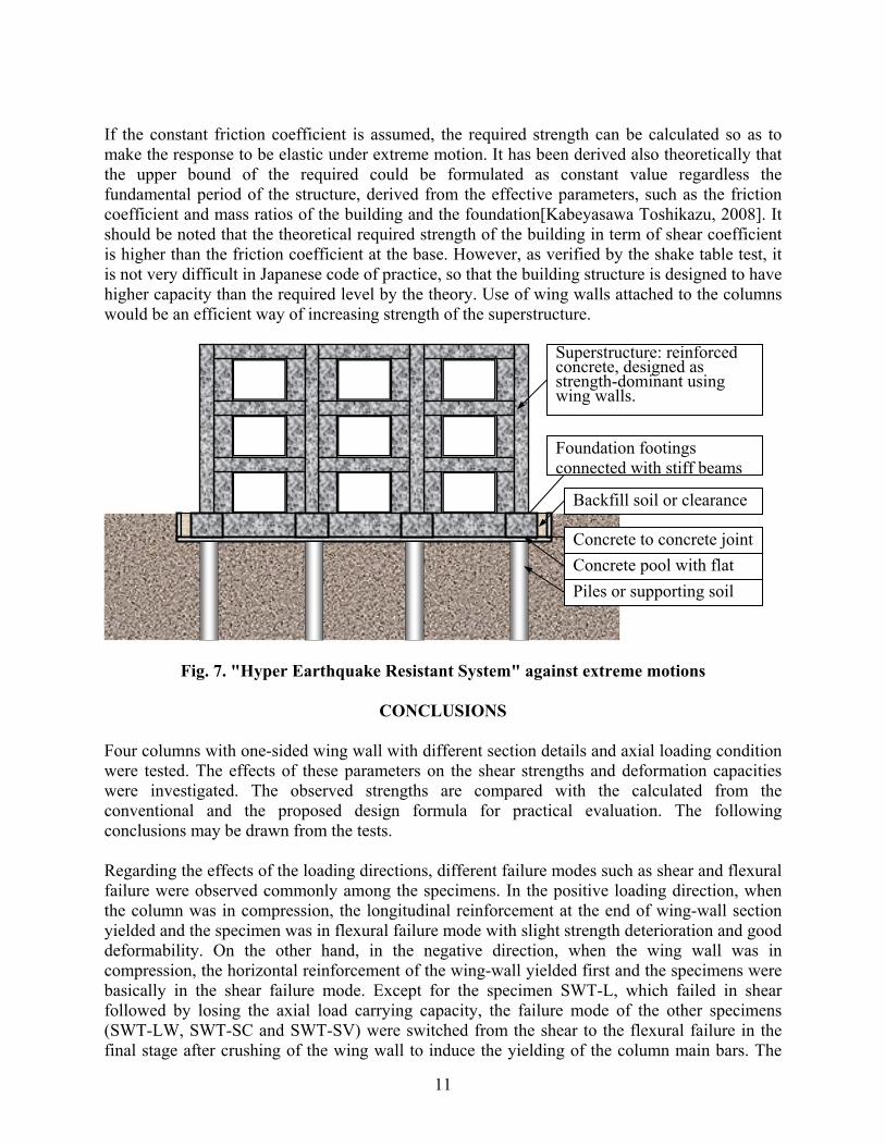
FAIL-SAFE DESIGN AGAINST EXTREME MOTIONS
In 2006, the authors have conducted shake table tests on full-scale three-story reinforced concrete buildings with flexible foundation at E-Defense, the world largest three-dimensional earthquake simulator, to verify the input loss at the base foundation. The test results are outlined in this paper, where the obvious reduction of damages to the building structures was observed owing to the slip behavior at the base foundation. Although the foundations were idealized, the results indicated the feasibility of development and practical application of the fail-safe system against possible and inexperienced extreme motions in the future, which incorporates the slip behavior positively to control damages or ensure safety. The slip behavior would occur only under very high ground acceleration, so that the response of the superstructure could be controlled to be minor as insensitive to the level and characteristics of possible extreme motion. Here let us call this simple system as "Hyper earthquake resistant system," for fail-safe design against extreme motions exceeding the design level. The conceptual elevation of the system is shown in Fig. 7. A flat concrete slab with standing wall, pool-shaped container, is to be constructed at the bottom of the base foundation supported by piles or foundation soil. The building may be designed normally but preferably with relatively higher lateral strength, or strength-dominant type using walls and columns with wing walls. The slab surface shall be leveled and smoothed to control the friction coefficient. The coefficient would be around 0.6 statically, which would be reduced in dynamic response down to 0.4 or lower as is observed in the shake table test.
0
200
400
600
800
1000
1200
1400
0 200 400 600 800 1000 1200 1400
SWT- L (+)SWT- L (- )SWT- LW (+)SWT- LW (- )SWT- SC (+)SWT- SC (- )SWT- SV (+)SWT- SV (- )
0
200
400
600
800
1000
1200
1400
0 200 400 600 800 1000 1200 1400
SWT- L (+)SWT- L (- )SWT- LW (+)SWT- LW (- )SWT- SC (+)SWT- SC (- )SWT- SV (+)SWT- SV (- )
0
200
400
600
800
1000
1200
1400
0 200 400 600 800 1000 1200 1400
SWT- L (+)SWT- L (- )SWT- LW (+)SWT- LW (- )SWT- SC (+)SWT- SC (- )SWT- SV (+)SWT- SV (- )
Cumulative with divided sections Qsu 1.2
1.0 0.8
BCJ 2007 Qsu 1.2
1.0 0.8
JBDPA 2001 Qsu 1.2
1.0 0.8
Test
(kN
)
Calculation (kN) Calculation (kN) Calculation (kN)
0
200
400
600
800
1000
1200
1400
0 200 400 600 800 1000 1200 1400
SWT- L (+)SWT- L (- )SWT- LW (+)SWT- LW (- )SWT- SC (+)SWT- SC (- )SWT- SV (+)SWT- SV (- )
Simplified ultimate flexural strength equation Qmu(Eq(4)) 1.2
1.0 0.8
0
200
400
600
800
1000
1200
1400
0 200 400 600 800 1000 1200 1400
SWT- L (+)SWT- L (- )SWT- LW (+)SWT- LW (- )SWT- SC (+)SWT- SC (- )SWT- SV (+)SWT- SV (- )
1.2 1.0 0.8
Perfect plastic theory Qmu
Test
(kN
)
Calculation (kN) Calculation (kN)
11
If the constant friction coefficient is assumed, the required strength can be calculated so as to make the response to be elastic under extreme motion. It has been derived also theoretically that the upper bound of the required could be formulated as constant value regardless the fundamental period of the structure, derived from the effective parameters, such as the friction coefficient and mass ratios of the building and the foundation[Kabeyasawa Toshikazu, 2008]. It should be noted that the theoretical required strength of the building in term of shear coefficient is higher than the friction coefficient at the base. However, as verified by the shake table test, it is not very difficult in Japanese code of practice, so that the building structure is designed to have higher capacity than the required level by the theory. Use of wing walls attached to the columns would be an efficient way of increasing strength of the superstructure.
Fig. 7. "Hyper Earthquake Resistant System" against extreme motions
CONCLUSIONS
Four columns with one-sided wing wall with different section details and axial loading condition were tested. The effects of these parameters on the shear strengths and deformation capacities were investigated. The observed strengths are compared with the calculated from the conventional and the proposed design formula for practical evaluation. The following conclusions may be drawn from the tests. Regarding the effects of the loading directions, different failure modes such as shear and flexural failure were observed commonly among the specimens. In the positive loading direction, when the column was in compression, the longitudinal reinforcement at the end of wing-wall section yielded and the specimen was in flexural failure mode with slight strength deterioration and good deformability. On the other hand, in the negative direction, when the wing wall was in compression, the horizontal reinforcement of the wing-wall yielded first and the specimens were basically in the shear failure mode. Except for the specimen SWT-L, which failed in shear followed by losing the axial load carrying capacity, the failure mode of the other specimens (SWT-LW, SWT-SC and SWT-SV) were switched from the shear to the flexural failure in the final stage after crushing of the wing wall to induce the yielding of the column main bars. The
Superstructure: reinforced concrete, designed as strength-dominant using wing walls.
Foundation footings connected with stiff beams
Backfill soil or clearance
Concrete to concrete joint Concrete pool with flat Piles or supporting soil

12
specimens SWT-LW with twice reinforcement ratio and SWT-SC with short wing wall showed flexural failure mode with high deformability in the positive direction. The specimen SWT-SV subjected to varying axial load showed lower stiffness and strength but higher ductility than SWT-SC under the constant axial load. The conventional equations for the ultimate shear strength overestimated the observed shear strengths of the column with one-sided wing-wall. The overestimation was more in cases of SWT-L and SWT-LW with longer wing wall. Proposed formula by cumulative method with divided sections provided conservative estimates for the ultimate shear strength observed in the tests on the columns with the wing wall irrespective of its wing wall length. The column with wing walls may be used in “hyper-earthquake resistant system,” to increase the strength of the superstructure, by which damages could be minor insensitive to possible extreme motions.
ACKNOWLEDGEMENT The tests were conducted at the structural laboratory of Earthquake Research Institute, University of Tokyo, under the support of Grants-in-Aid for Scientific Research (B), Grant No. 19360246, PI: Toshimi Kabeyasawa, by Japan Society for the Promotion of Science.
REFERENCES Building Center of Japan (2007), Guidelines for Standard Requirements on Building Structures
(in Japanese), BCJ. Japan Building Disaster Prevention Association (2001), Standard for Seismic Evaluation of
Existing Reinforced Concrete Buildings (in Japanese), JBDPA. Kabeyasawa, Toshimi, Kabeyasawa, T., Matsumori, T., Kabeyasawa, T. and Kim, Y.S. (2007a),
“3-D collapse tests and analyses of the three-story reinforced concrete buildings with flexible foundation,” Proc. of the 2007 Structures Congress, Long Beach, May 16-19
Kabeyasawa, Toshikazu, Matsumori, T., Kabeyasawa, T., Kabeyasawa, T. and Kim, Y.S. (2007b), “Plan of 3-D dynamic collapse tests on three-story reinforced concrete buildings with flexible foundation,” Proc. of the 2007 Structures Congress, Long Beach, May 16-19
Kabeyasawa, Toshimi, and Kabeyasawa, T. (2007c), “Shear Design Equation in Practice for Columns with Wing-Walls(in Japanese),” Proceedings of the 5th Annual Meeting, JAEE, 248-249.
Kabeyasawa, Toshinori, Kabeyasawa, T., Tojo, Y. and Kabeyasawa, T. (2008), “Experimental Study on Columns with Wing Walls failing in Shear”, Proceedings of the Japan Concrete Institute, Vol.30, No.3, 115-120 (in Japanese)
Tojo, Y., Kabeyasawa, T., Kabeyasawa, T. and Kim, Y.S. (2008), “Experimental Study on Column with Wing Walls Yielding in Flexure”, Proceedings of the Japan Concrete Institute, Vol.30, No.3, 109-114 (in Japanese).
Kabeyasawa, Toshikazu, Kabeyasawa, Toshimi. (2008). Nonlinear soil-structure interaction theory for low-rise reinforced concrete buildings based on the full-scale shake table test at E-Defense, Paper submitted to Proceedings of 14th World Conference on Earthquake Engineering, Beijing, China.