Embed Size (px)
Citation preview

1
Today’s ClassE R Model
CS F212 Database Systems

2
E-R Diagram with a Ternary Relationship
3
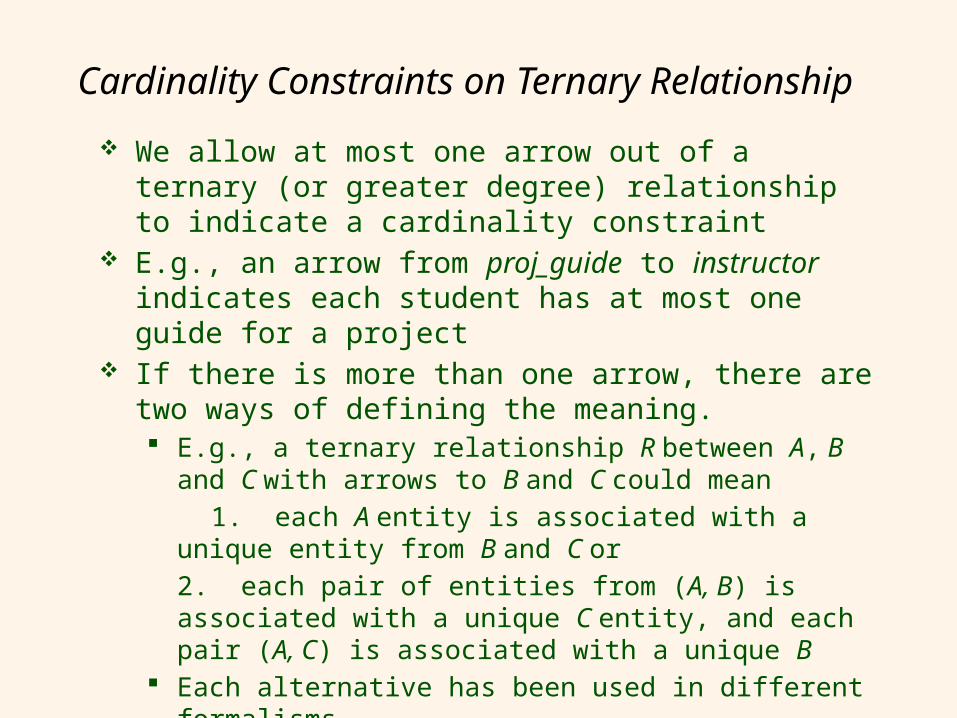
Cardinality Constraints on Ternary Relationship
We allow at most one arrow out of a ternary (or greater degree) relationship to indicate a cardinality constraint
E.g., an arrow from proj_guide to instructor indicates each student has at most one guide for a project
If there is more than one arrow, there are two ways of defining the meaning. E.g., a ternary relationship R between A, B and C
with arrows to B and C could mean 1. each A entity is associated with a unique entity
from B and C or 2. each pair of entities from (A, B) is associated with a unique C entity, and each pair (A, C) is associated with a unique B
Each alternative has been used in different formalisms
To avoid confusion we outlaw more than one arrow

4
E-R Diagram for a University Enterprise

5
Design Constraints on a Specialization/Generalization
Constraint on which entities can be members of a given lower-level entity set. condition-defined
• Example: all customers over 65 years are members of senior-citizen entity set; senior-citizen ISA person.
user-defined Constraint on whether or not entities may belong to
more than one lower-level entity set within a single generalization. Disjoint
• an entity can belong to only one lower-level entity set
• Noted in E-R diagram by having multiple lower-level entity sets link to the same triangle
Overlapping• an entity can belong to more than one lower-level
entity set

6
Design Constraints on a Specialization/Generalization (Cont.)
Completeness constraint -- specifies whether or not an entity in the higher-level entity set must belong to at least one of the lower-level entity sets within a generalization. total: an entity must belong to one of the
lower-level entity sets partial: an entity need not belong to one
of the lower-level entity sets (default)

7
Aggregation
Consider the ternary relationship proj_guide, which we saw earlier
Suppose we want to record evaluations of a student by a guide on a project

8
Aggregation (Cont.) Relationship sets eval_for and
proj_guide represent overlapping information Every eval_for relationship corresponds to
a proj_guide relationship However, some proj_guide relationships
may not correspond to any eval_for relationships • So we can’t discard the proj_guide relationship
Eliminate this redundancy via aggregation Treat relationship as an abstract entity Allows relationships between relationships Abstraction of relationship into new entity

9
Aggregation (Cont.) Without introducing redundancy, the following diagram
represents: A student is guided by a particular instructor on a
particular project A student, instructor, project combination may have an
associated evaluation

10
Aggregationo Relationship sets works_on and manages represent
overlapping informationo Every manages relationship corresponds to a works_on
relationshipo However, some works_on relationships may not
correspond to any manages relationships o So we can’t discard the works_on relationship
o Eliminate this redundancy via aggregationo Treat relationship as an abstract entityo Allows relationships between relationships o Abstraction of relationship into new entity
o Without introducing redundancy, the following diagram represents:o An employee works on a particular job at a particular
branch o An employee, branch, job combination may have an
associated manager

11
E-R Diagram With Aggregation

12
Aggregation Used when we
have to model a relationship involving (entity sets and) a relationship set. Aggregation
allows us to treat a relationship set as an entity set for purposes of participation in (other) relationships.
Aggregation vs. ternary relationship: Monitors is a distinct relationship, with a descriptive attribute. Also, can say that each sponsorship is monitored by at most one employee.
budgetdidpid
started_on
pbudgetdname
until
DepartmentsProjects Sponsors
Employees
Monitors
lotname
ssn
since

13
Summary of Symbols Used in E-R Notation

14
Symbols Used in E-R Notation (Cont.)

15
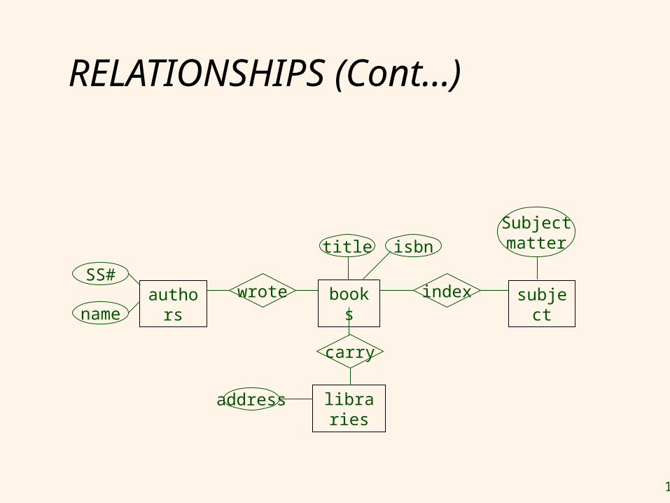
RELATIONSHIPS (Cont…)
Example: A library database contains a listing of authors that have written books on various subjects (one author per book). It also contains information about libraries that carry books on various subjects.
Entity sets: authors, subjects, books, librariesRelationship sets: wrote, carry, indexed
16
RELATIONSHIPS (Cont…)
carry
books indexwrote subjectauthorsSS#
name
title
librariesaddress
isbn
Subjectmatter

17
RELATIONSHIPS (Cont…)
carry
books indexwrote subjectauthorsSS#
name
title
libraries
quantity
address
isbn
Subjectmatter

18
E-R Design Decisionso The use of an attribute or entity set to represent
an object.o Whether a real-world concept is best expressed
by an entity set or a relationship set.o The use of a ternary relationship versus a pair
of binary relationships.o The use of a strong or weak entity set.o The use of specialization/generalization –
contributes to modularity in the design.o The use of aggregation – can treat the
aggregate entity set as a single unit without concern for the details of its internal structure.
18

19
Conceptual Design Using the ER Model Design choices:
Should a concept be modeled as an entity or an attribute?
Should a concept be modeled as an entity or a relationship?
Identifying relationships: Binary or ternary? Aggregation?
Constraints in the ER Model: A lot of data semantics can (and should) be
captured. But some constraints cannot be captured in ER
diagrams.
19

20
Design Techniques
1. Avoid redundancy.2. Limit the use of weak entity sets.3. Don’t use an entity set when an
attribute will do.

21
Valid E/R Diagrams
An E/R diagram is valid if and only if: It is syntactically correct (e.g.
specifies all key constraints,…) It specifies the entity types,
relationship types, attribute types, and subtype relationships necessary to satisfy all information requirements.
It does not specify any invalid constraints.

22
Priorities when Choosing Between Valid E/R Diagrams
1. Express all constraints (you can express!)
2. Use and do not change terminology and class structure of the application domain
3. Keep it simple (avoid defining entity types that do not serve any purpose)
4. Avoid redundancy (but derived attributes are okay)!
23
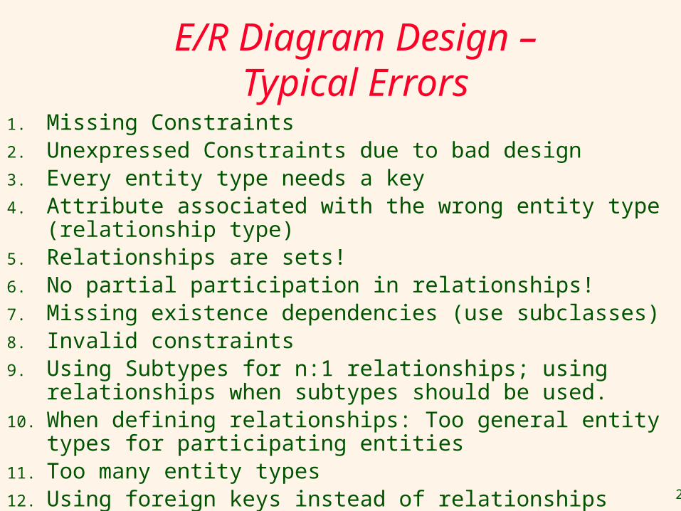
E/R Diagram Design – Typical Errors
1. Missing Constraints2. Unexpressed Constraints due to bad design3. Every entity type needs a key4. Attribute associated with the wrong entity type (relationship type)5. Relationships are sets!6. No partial participation in relationships!7. Missing existence dependencies (use subclasses)8. Invalid constraints9. Using Subtypes for n:1 relationships; using relationships when
subtypes should be used.10. When defining relationships: Too general entity types for participating
entities 11. Too many entity types12. Using foreign keys instead of relationships

24
Other Issues in E/R Design
1. No relationships of relationships --- solution: create an entity type that represent instances of the relationship (or use aggregation as discussed in the textbook)
2. value or entity type --- solution: choose entity type if it helps expressing constraints; otherwise, use value-type.

25
IPL E/R Design ---Ungraded Homework --- due: Wed.,
Feb. 19,2014
Design an Entity-Relationship Diagram that models the following entities and relationships in the world of Cricket (IPL): teams, players, games, managers and contracts. Each (IPL) team has a unique team name, and a city it plays in. Each person being part of the IPL has a unique IDNO and a name. Additionally, for players their weight, height, playing position and birth dates are of importance. Players have a contract with at most one team and receive a salary for their services, and teams have at least 15 and at most 49 players under contract. Each team has one to three managers; managers can work for at most 4 teams and receive a salary for each of their employments. Players cannot be managers. A game involves a home-team and visiting-team; additionally, the day of the game, and the score of the game are of importance; teams play each other several times in a season (not on the same day!). Moreover, for each game played we like to know which players participated in the game and how many minutes they played.
Indicate the cardinalities for each relationship type; assign roles (role names) to
each relationship if there are ambiguities! Use sub-types, if helpful to express constraints!

26
A University Database Design an entity-relationship diagram that describes
the following objects in a university application: students, professors, and courses. Students take a course in a particular semester and receive a grade for their performance. Sometimes students take the same course again in different semester. There are no limits on how many courses a student can take, and on how many students completed a particular course. Each student has exactly one advisor, who must be a professor, whereas each professor allowed being the advisor of at most 20 students. Courses have a unique course number and a course title. Students and professors have a name and a unique SSN. Students additionally have a GPA and a single or multiple major.

27
A movie studio might have several film crews. The crews might be designated by a given studio as crew 1, crew 2, and so on. However, other studios might use the same designations for crews, so the attribute number is not a key for crews. Rather, to name a crew uniquely, we need to give both the name of the studio to which it belongs and the number of crew. The key for the weak entity set Crews is its own number attribute and the name attribute of the unique studio to which the crew is related by the many-one Unit-of relationship.

28
Exercise 2.4 A company database needs to store information about employees (identified by ssn, with salary and phone as attributes), departments (identified by dno, with dname and budget as attributes), and children of employees (with name and age as attributes). Employees work in departments; each department is managed by an employee; a child must be identified uniquely by name when the parent (who is an employee; assume that only one parent works for the company) is known. We are not interested in information about a child once the parent leaves the company. Draw an ER diagram that captures this information.

29
Summary of Conceptual Design
Conceptual design follows requirements analysis, Yields a high-level description of data to be stored
ER model popular for conceptual design Constructs are expressive, close to the way
people think about their applications. Note: There are many variations on ER model
• Both graphically and conceptually Basic constructs: entities, relationships, and
attributes (of entities and relationships). Some additional constructs: weak entities, ISA
hierarchies, and aggregation.
30
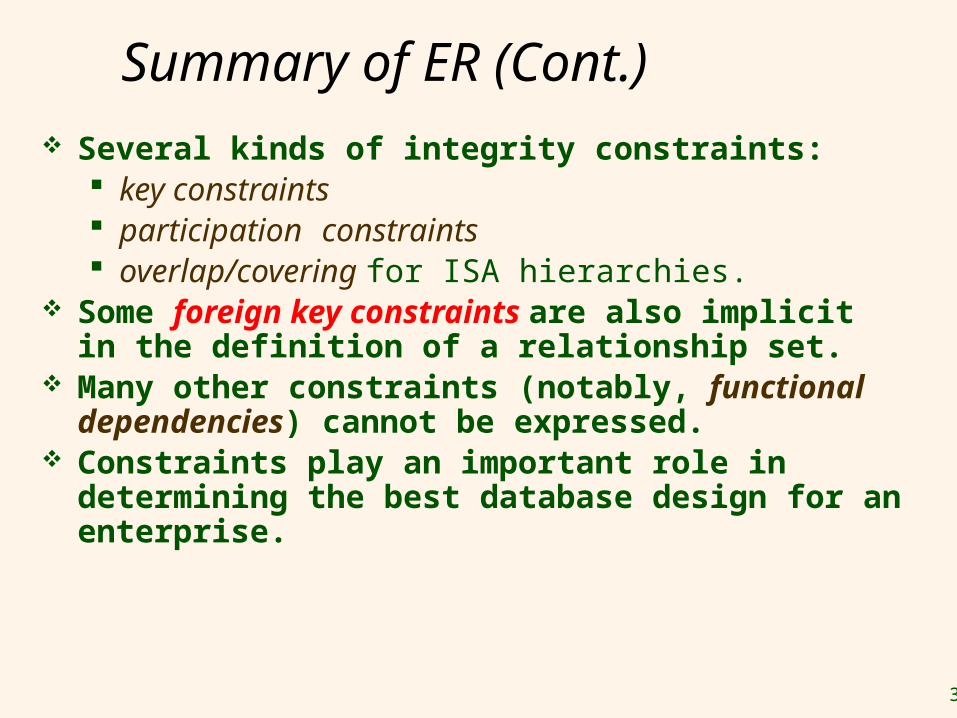
Summary of ER (Cont.) Several kinds of integrity constraints:
key constraints participation constraints overlap/covering for ISA hierarchies.
Some foreign key constraints are also implicit in the definition of a relationship set.
Many other constraints (notably, functional dependencies) cannot be expressed.
Constraints play an important role in determining the best database design for an enterprise.

31
Summary of ER (Cont.) ER design is subjective. There are often
many ways to model a given scenario! Analyzing alternatives can be tricky,
especially for a large enterprise. Common choices include: Entity vs. attribute, entity vs. relationship, binary
or n-ary relationship, whether or not to use ISA hierarchies, aggregation.
Ensuring good database design: resulting relational schema should be analyzed and refined further. Functional Dependency information and
normalization techniques are especially useful.

32
From ER Model to Relational Model
So… how do we convert an ER diagram into a table?? Simple!!
Basic Ideas: Build a table for each entity set Build a table for each relationship set if
necessary (more on this later) Make a column in the table for each attribute
in the entity set Indivisibility Rule and Ordering Rule Primary Key

33
ER to Relational Model
General principles Entity set => a relation with same
attributes Relationship => a relation whose attributes
are keys from participating entity sets + descriptive attributes if any
Special situations Weak entity sets Entity Hierarchies (ISA relationships) Merging relations

34
Example – Strong Entity Set
SID Name Major GPA
1234 John CS 2.8
5678 Mary EE 3.6
Student
SID Name
Major GPA
Advisor Professor
PSRN Name
Dept
PSRN Name Dept
9999 Smith Math
8888 Lee CS

35
Reduction to Relation Schemas Entity sets and relationship sets can be
expressed uniformly as relation schemas that represent the contents of the database.
A database which conforms to an E-R diagram can be represented by a collection of schemas.
For each entity set and relationship set there is a unique schema that is assigned the name of the corresponding entity set or relationship set.
Each schema has a number of columns (generally corresponding to attributes), which have unique names.

36
Logical DB Design: ER to Relational
Entity sets to tables:
CREATE TABLE Employees (psrn INTEGER, name CHAR(20), dept CHAR(12), PRIMARY KEY (ssn))
Employees
psrnname
dept

37
Representing Entity Sets With Simple Attributes A strong entity set reduces to a schema with the
same attributesstudent(ID, name, tot_cred)
A weak entity set becomes a table that includes a column for the primary key of the identifying strong entity set section ( course_id, sec_id, sem, year )

38
Representation of Weak Entity Set Weak Entity Set Cannot exists alone To build a table/schema for weak entity set
Construct a table with one column for each attribute in the weak entity set
Remember to include discriminator Augment one extra column on the right side of
the table, put in there the primary key of the Strong Entity Set (the entity set that the weak entity set is depending on)
Primary Key of the weak entity set = Discriminator + foreign key

39
Representation of Relationship Set
--This is a little more complicated-- Unary/Binary Relationship set
Depends on the cardinality and participation of the relationship
Two possible approaches N-ary (multiple) Relationship set
Primary Key Issue Identifying Relationship
No relational model representation necessary

40
Representing Relationship SetUnary/Binary Relationship For one-to-one relationship w/out total
participation Build a table with two columns, one column
for each participating entity set’s primary key. Add successive columns, one for each descriptive attributes of the relationship set (if any).
For one-to-one relationship with one entity set having total participation Augment one extra column on the right side
of the table of the entity set with total participation, put in there the primary key of the entity set without complete participation as per to the relationship.

41
Example – One-to-One Relationship Set
SID Maj_ID Co S_Degree
9999 07 1234
8888 05 5678
Student
SID Name
Major
GPA
ID Code
Major
study
* Primary key can be either SID or Maj_ID_Co
Degree

42
Example – One-to-One Relationship Set
SID Name Major GPA LP_S/N Hav_Cond
9999 Bart Economy -4.0 123-456 Own
8888 Lisa Physics 4.0 567-890 Loan
Student
SID Name
Major
GPA
S/N #
Laptop
Have
* Primary key can be either SID or LP_S/N
Condition
Brand
1:1 Relationship
43
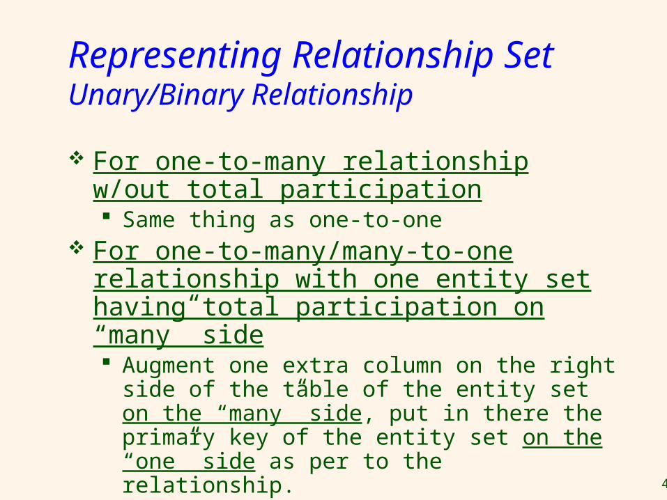
Representing Relationship SetUnary/Binary Relationship For one-to-many relationship w/out total
participation Same thing as one-to-one
For one-to-many/many-to-one relationship with one entity set having total participation on “many” side Augment one extra column on the right side
of the table of the entity set on the “many” side, put in there the primary key of the entity set on the “one” side as per to the relationship.

44
Example – Many-to-One Relationship Set
SID Name Major GPA Pro_SSN Ad_Sem
9999 Bart Economy -4.0 123-456 Fall 2006
8888 Lisa Physics 4.0 567-890 Fall 2005
Student
SID Name
Major
GPA
SSN
Professor
* Primary key of this table is SID
Semester
Name
N:1 Relationship
Dept
Advisor

45
Representing Relationship SetUnary/Binary Relationship For many-to-many relationship
Same thing as one-to-one relationship without total participation.
Primary key of this new schema is the union of the foreign keys of both entity sets.
No augmentation approach possible…

46
Representing Relationship Sets A many-to-many relationship set is represented
as a schema with attributes for the primary keys of the two participating entity sets, and any descriptive attributes of the relationship set.
Example: schema for relationship set advisoradvisor = (s_id, i_id)

47
Redundancy of Schemas Many-to-one and one-to-many relationship sets that are total on the
many-side can be represented by adding an extra attribute to the “many” side, containing the primary key of the “one” side
Example: Instead of creating a schema for relationship set inst_dept, add an attribute dept_name to the schema arising from entity set instructor

48
Redundancy of Schemas For one-to-one relationship sets, either side
can be chosen to act as the “many” side That is, extra attribute can be added to either of
the tables corresponding to the two entity sets If participation is partial on the “many” side,
replacing a schema by an extra attribute in the schema corresponding to the “many” side could result in null values
The schema corresponding to a relationship set linking a weak entity set to its identifying strong entity set is redundant. Example: The section schema already contains
the attributes that would appear in the sec_course schema

49
Composite and Multivalued Attributes
Composite attributes are flattened out by creating a separate attribute for each component attribute Example: given entity set instructor
with composite attribute name with component attributes first_name and last_name the schema corresponding to the entity set has two attributes name_first_name and name_last_name• Prefix omitted if there is no
ambiguity Ignoring multivalued attributes,
extended instructor schema is instructor(ID, first_name, middle_initial,
last_name,street_number, street_name, apt_number, city, state, zip_code, date_of_birth)

50
Composite and Multivalued Attributes A multivalued attribute M of an entity E is
represented by a separate schema EM Schema EM has attributes corresponding to the
primary key of E and an attribute corresponding to multivalued attribute M
Example: Multivalued attribute phone_number of instructor is represented by a schema: inst_phone= ( ID, phone_number)
Each value of the multivalued attribute maps to a separate tuple of the relation on schema EM• For example, an instructor entity with
primary key 22222 and phone numbers 456-7890 and 123-4567 maps to two tuples: (22222, 456-7890) and (22222, 123-4567)

51
Representing Composite Attribute
Relational Model Indivisibility Rule Applies One column for each component attribute NO column for the composite attribute
itself
Professor
SSN Name
Address
SSN Name Street City
9999 Dr. Smith 50 1st St. Fake City
8888 Dr. Lee 1 B St. San Jose
Street City

52
Representing Multivalue Attribute
For each multivalue attribute in an entity set/relationship set Build a new relation schema with two
columns One column for the primary keys of the
entity set/relationship set that has the multivalue attribute
Another column for the multivalue attributes. Each cell of this column holds only one value. So each value is represented as an unique tuple
Primary key for this schema is the union of all attributes

53
Example – Multivalue attribute
SID Name Major GPA
1234 John CS 2.8
5678 Homer EE 3.6
Student
SID Name
Major GPA
Stud_SID Children
1234 Johnson
1234 Mary
5678 Bart
5678 Lisa
5678 Maggie
Children
The primary key for this table is Student_SID + Children, the union of all attributes

54
Multivalued Attributes (Cont.) Special case:entity time_slot has only one
attribute other than the primary-key attribute, and that attribute is multivalued Optimization: Don’t create the relation corresponding
to the entity, just create the one corresponding to the multivalued attribute
time_slot(time_slot_id, day, start_time, end_time) Caveat: time_slot attribute of section (from
sec_time_slot) cannot be a foreign key due to this optimization

55
Design Issues Use of entity sets vs. attributes
Use of phone as an entity allows extra information about phone numbers (plus multiple phone numbers)

56
Design Issues Use of entity sets vs. relationship
setsPossible guideline is to designate a relationship set to describe an action that occurs between entities

57
Design Issues Binary versus n-ary relationship sets
Although it is possible to replace any nonbinary (n-ary, for n > 2) relationship set by a number of distinct binary relationship sets, a n-ary relationship set shows more clearly that several entities participate in a single relationship.
Placement of relationship attributes e.g., attribute date as attribute of advisor or as
attribute of student

58
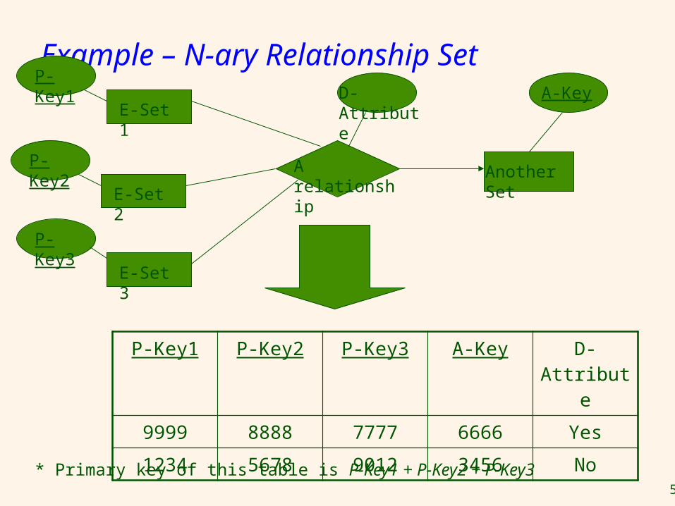
Representing Relationship SetN-ary Relationship Intuitively Simple
Build a new table with as many columns as there are attributes for the union of the primary keys of all participating entity sets.
Augment additional columns for descriptive attributes of the relationship set (if necessary)
The primary key of this table is the union of all primary keys of entity sets that are on “many” side
That is it, we are done.
59
Example – N-ary Relationship Set
P-Key1 P-Key2 P-Key3 A-Key D-Attribute
9999 8888 7777 6666 Yes
1234 5678 9012 3456 No
E-Set 1
P-Key1
Another Set
* Primary key of this table is P-Key1 + P-Key2 + P-Key3
D-Attribute
A relationship
A-Key
E-Set 2
P-Key2
E-Set 3
P-Key3