Embed Size (px)
Citation preview
November 26, 2009 11:49 WSPC/253-RAST : SPI-J100 00020
Reviews of Accelerator Science and TechnologyVol. 2 (2009) 111–131c© World Scientific Publishing Company
High Frequency Linacs for Hadrontherapy∗
Ugo Amaldi
University Milano-Bicocca and TERA Foundation,Via Puccini 11, I-28100 Novara, Italy
Saverio Braccini
Albert Einstein Center for Fundamental Physics andLaboratory for High Energy Physics
University of BernSidlerstrasse 5, CH-3012 Bern, Switzerland
Paolo Puggioni
ADAM SA, Rue de Lyon 62,CH-1211 Geneva, Switzerland
The use of radiofrequency linacs for hadrontherapy was proposed about 20 years ago, but only recently has it beenunderstood that the high repetition rate together with the possibility of very rapid energy variations offers an optimalsolution to the present challenge of hadrontherapy: “paint” a moving tumor target in three dimensions with a pencilbeam. Moreover, the fact that the energy, and thus the particle range, can be electronically adjusted implies that noabsorber-based energy selection system is needed, which, in the case of cyclotron-based centers, is the cause of materialactivation. On the other side, a linac consumes less power than a synchrotron. The first part of this article describes themain advantages of high frequency linacs in hadrontherapy, the early design studies, and the construction and test ofthe first high-gradient prototype which accelerated protons. The second part illustrates some technical issues relevantto the design of copper standing wave accelerators, the present developments, and two designs of linac-based protonand carbon ion facilities. Superconductive linacs are not discussed, since nanoampere currents are sufficient for therapy.In the last two sections, a comparison with circular accelerators and an overview of future projects are presented.
Keywords: Carbon ion therapy; cyclinac; dose delivery; hadrontherapy; linac; medical accelerators; particle therapy;proton therapy.
1. The Challenges ConfrontingHadrontherapy
Hadrontherapy, the treatment of tumors with hadronbeams, is a new frontier in cancer radiation ther-apy which is nowadays undergoing rapid develop-ment. Since its beginnings, more than 60,000 patientshave been treated with protons and light ions inthe world [1]. However, about one third of all thepatients treated with proton therapy have beenirradiated in nuclear and particle physics laborato-ries by means of nondedicated accelerators. More-over, less than 2% of all these patients have beentreated with pencil beam delivery systems in which
the tumor target is uniformly painted with a largenumber of successive spots, thus making the bestpossible use of the properties of charged hadronbeams. This fundamental technical advance tookplace at the end of the last century in two physicslaboratories: the Paul Scherrer Institute (PSI; inVilligen, Switzerland), where the spot scanningtechnique was developed for protons [2], and theGesellschaft fur Schwerionenforschung (GSI; inDarmstadt, Germany), where the raster scanningtechnique was developed for carbon ions [3]. In 2009almost all hospital-based centers are still using pas-sive dose delivery systems in which the beam is
∗In memory of Mario Weiss, who led the developments of linacs at TERA from 1993 to 2003.
111

November 26, 2009 11:49 WSPC/253-RAST : SPI-J100 00020
112 U. Amaldi, S. Braccini & P. Puggioni
scattered in successive targets and flattened and/orshaped with appropriate filters and collimators [4].In some centers, the more advanced semiactive “layerstacking” technique is used [5].
In the next few years, hadrontherapy centersmust use new approaches to the delivery of thedose if they want to keep pace with the competitionof conventional radiotherapy — mainly performedwith x-rays produced by electron linacs. Indeed,new techniques have been introduced in the lastten years to conformally cover moving tumors withmany crossed beams and spare more and more thesurrounding healthy tissues. Many hospitals rou-tinely employ intensity-modulated radiation therapy(IMRT) [6] and are starting to use image-guided radi-ation therapy (IGRT) [7, 8]. Further improvementshave recently been brought by Tomotherapy [9, 10]and rapid arc technologies [11]. Hadron dose deliv-ery systems have to become more sophisticated inorder to bring to full fruition the intrinsic advan-tages of the dose distribution due to a single narrowion beam characterized, at the end of its range inmatter, by the well-known Bragg peak.
Proton beams of energy between 200 and250MeV (and very low currents, about 1 nA on tar-get) and carbon ion beams of energy between 3500and 4500MeV (and currents of about 0.1 nA on tar-get) are advantageous in the treatment of deep-seated tumors because of four physical properties[12]. Firstly, they deposit their maximum energy den-sity abruptly at the end of their range. Secondly,they penetrate the patient with limited diffusionand range straggling (from this point of view car-bon ion beams are about three times better thanproton beams). Thirdly, being charged, they can eas-ily be formed as narrow-focused and scanned pen-cil beams of variable penetration depth, so that anypart of a tumor can be accurately irradiated. Thefourth physical property is linked to radiobiologyand pertains to ions, particularly carbon ions: sinceeach ion leaves in a traversed cell about 24 timesmore energy than a proton having the same range,the damage produced in crossing the DNA of a cellnucleus is different and includes a large proportion ofmultiple close-by double strand breaks. This damagecannot be repaired by the usual cell repair mecha-nisms, so that the effects are qualitatively differentfrom the ones produced by the other radiations; forthis reason, carbon ions can control tumors, which
are otherwise radioresistant to both protons andx-rays [13].
The first property is the main reason for usingcharged hadrons in radiotherapy, since the singlebeam dose distribution is in all cases superior to thatof x-rays, which has an almost exponential energydeposition in matter after a maximum dose deliv-ered only a few centimeters inside the patient’s body.Thus beams of charged hadrons allow in principle amore conformal treatment of deep-seated tumors thanbeams of x-rays; they give minimal doses to the sur-rounding tissues, and — in the case of carbon ions —open the way to the control of radioresistant tumors.
The challenge of hadrontherapy is in making fulluse of the above four properties, especially when thetumor moves, mostly because of the breathing of thepatient. The fact that protons and ions have an elec-tric charge, the third property, is the key to any fur-ther development but, surprisingly enough, till nowpractically all therapy beams have been shaped bycollimators and absorbers as if hadrons had no elec-tric charge.
In the GSI active “raster scanning” technique, apencil beam of 4–10mm width (FWHM) is movedin the transverse plane almost continuously (with-out switching off the beam) by two bending magnetslocated about 10m upstream of the patient. Afterpainting a section of the tumor, the energy of thebeam extracted from the carbon ion synchrotron isreduced to paint a less deep layer. In practice, toobtain a variable speed the beam is moved in stepsthree times smaller than the FWHM of the spotand the next small step is triggered when a prede-termined integral of the fluency has been recordedby the ionization chambers placed just before thepatient. In this approach the beam is always on.
In the PSI active “spot scanning” technique(which is also called “hold and shoot”), the 8–10mm(FWHM) spot is moved (switching off the beam) bymuch larger steps (of the order of 75% of the FWHMof the spot) and, as in the previous case, the trans-verse movement — which takes about 2 ms — is trig-gered by ionization chambers measuring the fluence.During the movement of the spot the proton beamextracted from the cyclotron is interrupted for 5msby means of a fast kicker.
In both cases the tumor target is painted onlyonce and this is an inconvenience in the case of mov-ing organs, since any movement can cause important

November 26, 2009 11:49 WSPC/253-RAST : SPI-J100 00020
High Frequency Linacs for Hadrontherapy 113
Fig. 1. The feedback system — numerically and experimentally studied at GSI — compensates for the movements of the organsacting, with two bending magnets, to correct the transverse movements and, with absorbers of variable thickness, to compensate
for longitudinal movements [14]. (Courtesy of GSI .)
local under- or overdosages. Three strategies havebeen considered to reduce such effects. In order ofincreasing complexity, they are:
(1) In the irradiation of the thorax and the abdomi-nal region, the dose delivery is synchronized withthe patient expiration phase in a process called“respiratory gating,” so that the effects on thedistribution of the dose due to the movements ofthe organs are reduced to a minimum (this tech-nique is also used in conventional radiotherapy);
(2) The tumor is painted many times in three dimen-sions so that the movements of the organs (ifnot too large) can cause only small (≤ 3%)overdosages and/or underdosages;
(3) The movement is detected by a suitable system,which outputs in real time the 3D position of thetumor, and a set of feedback loops compensatesfor the predicted position in the dose deliveryplan with on-line adjustments of the transverseand longitudinal locations of the following spots,as shown in Fig. 1 [14].
An optimal delivery mechanism should be such asto allow the use of any combination of these three
approaches: respiratory gating, multipainting andactive angular/energy feedback.
To face these challenges, innovative technolog-ical solutions are developed. In this framework,linacs, which are fast-cycling accelerators, offer sev-eral advantages and are particularly suited to themultipainting of moving organs, as discussed inSubsecs. 5.2 and 6.1.
2. Linacs Enter Hadrontherapy
This section describes the early design studies of thelinacs for proton therapy in a chronological order,from the first proposals in 1989 to the Top-projectin 1995.
The focus is on linacs which produce beamsdirectly employed for treating patients, so the devel-opments in the design of hadron low energy linacsused as injectors of medical synchrotrons are not dis-cussed. The reader is referred to the recent papers byU. Ratzinger and collaborators [15, 16].
2.1. The first proton linac for therapy
designed at FNAL
The first design of a proton linac for therapy datesback to 1989 [17–19], when at FNAL J. Lennox et al.

November 26, 2009 11:49 WSPC/253-RAST : SPI-J100 00020
114 U. Amaldi, S. Braccini & P. Puggioni
proposed a hospital-based accelerator for (i) eyetreatment with 66MeV protons, (ii) fast neutrontherapy, (iii) boron neutron capture therapy and (iv)isotope production. This multipurpose 24-m-longaccelerator had a duoplasmatron H+ source, a lowenergy beam transport (LEBT) system, a radiofre-quency quadrupole linac (RFQ) and a drift tube linac(DTL) that could deliver up to a 180µA averagecurrent. The advertised advantages, with respect tothe usual approach based on cyclotrons, were thehigher dose rate, the limited power costs and theoperation in a safer radioactive area.
The RFQ [20, 21] is efficient for very low betaparticles (β < 0.06). The 3MeV protons wereinjected into a DTL (consisting of four independentmodules) operating at 425MHz with a low repetitionrate (30Hz) and relatively long pulses (315µs). Theprotons, focused by a system of permanent magneticquadrupoles (PMQs), could be accelerated at five dif-ferent energies (3, 7, 27, 47 and 66MeV) by switch-ing off a certain number of DTL modules. The energymodulation was considered important for obtaining abeam suitable for the applications requiring differentproton energies.
2.2. A 3 GHz high repetition rate
solution
In 1991, R. Hamm, K. Crandall and J. Potter [22]of Accsys Technology proposed a linac solution com-posed of three sections. The system is made up ofan RFQ–DTL operating at 499.5MHz, followed bya 3 GHz side-coupled cavity linac (SCL, now calledCCL) that accelerates protons from 70 to 250MeV(Fig. 2). The energy modulation could be achievedby switching off the modules and by using degradingfoils. This design was based on a higher frequency(3 GHz), a higher repetition rate (100–300Hz) andshorter beam pulses (1–3µs) than that of Lennoxet al.
Fig. 2. Schematic layout of the model PL-250 proton therapy linac designed in 1991 by R. Hamm, K. Crandall and J. Potter[22].
The high frequency enhances the shuntimpedance (Z ∼ f1/2 [23]) and, for the same powerconsumption, the total length of the acceleratorcould be reduced by increasing the mean electricfield.
Note that the high repetition rate favors beamscanning while the small output beam size andemittance allow a compact gantry design. The posi-tion of the beam can be moved fast (up to 100–300 times in a second) to cover all the area of thetreatment. Moreover, the short beam pulses meanan affordable cost of the wall-plug power, becausethe duty cycle of the RF system (i.e. the repetitionrate times the RF effective pulse length) is alwayssmaller than 10−3.
2.3. A 1.28GHz linac as booster of an
existing cyclotron
In 1992, M. P. S. Nightingale et al. proposed lin-ear accelerators as boosters of existing hospitalcyclotrons, so as to have a cost-effective machine[24]. The 1.28GHz CCL was designed to boost pro-tons from 62.5MeV to 200MeV in about 20m. Themain problem of this structure is the matching withthe cyclotron, which usually produces a beam of50–300µA with large emittance. The ScanditronixMC60 cyclotron of the Clatterbridge hospital, con-sidered in this first study, could be modified to pro-duce a 100µA pulsed beam of about 20µs with atransverse rms emittance of 9.3π mm mrad, as wasdemonstrated in 1998 in a study conducted for theTERA Foundation [25].
The design synchronous phase was ϕs = −30,so that the longitudinal capture efficiency (3ϕs/360[26]) was about 25%. The duty cycle of the RF wasset at 0.1%, so that the accelerated average currentwas about 4×10³ times smaller than the one injectedin the linac.

November 26, 2009 11:49 WSPC/253-RAST : SPI-J100 00020
High Frequency Linacs for Hadrontherapy 115
The bore radius was calculated so that theFODO structure of the series of PMQs had twice theacceptance of the input emittance ε; the 70 trans-verse phase advance guaranteed a minimum β Twissparameter in each quadrupole [27], so that the trans-verse physical dimension of the beam (∼√
εβ) wassmaller than the linac beam hole.
2.4. A traveling wave solution
An innovative approach was proposed by D. Tronc in1993 [28, 29], when he designed an H-coupled 3GHztraveling wave (TW) structure. The claim was thatthis TW linac has higher shunt impedance and ahigher quality factor than the classical CCL. Byremoving the side-coupling cavities, the acceleratorhas a smaller diameter, so that simultaneous accel-eration and focusing become feasible with the intro-duction of a special external helical focusing [30–32].
In order to get a large Q value and high shuntimpedance, the length of the cavities should be aslarge as possible. This is even more effective at highfrequencies (small wavelength λ) and low beta values,when the lengths naturally shrink to maintain thesynchronism between the particle and the RF wave.The formula that determines the distance d betweenthe midplanes of two accelerating cavities is
d =βλ
2π∆φ, (1)
where ∆φ is the phase shift between two adjacentcells.
Tronc chose a forward TW linac working in the−3/4π mode, which means that ∆φ = (2π−3/4π) =5/4π. Thus, the length of the cavities of this TWlinac is larger than that of a CCL that works in theπ/2 mode and has ∆φ = π. According to Tronc’s cal-culations, for β = 0.25 (30MeV protons), the shuntimpedance of a −3/4π TW linac is about 50% higherthan for an equivalent CCL structure.
So far, this has been the only attempt to designa TW linac for proton therapy.
The main characteristics of the four approachesdescribed above are listed in Table 1.
2.5. Further designs based on standing
wave structures
From 1993 on, and in parallel with the work donefor the hadrontherapy center now in construction
Table 1. Characteristics of the four proposals.
Subsection Type Freq. Energy Length(MHz) (MeV) (m)
2.1 SW 425 0–66 242.2 SW 2998 0–250 282.3 SW 1280 62–200 202.4 TW 2998 0–250 25
in Pavia, the CNAO (Centro Nazionale di Adroter-apia Oncologica, Italy [33]), one of us (U. A.) pro-posed [34, 35] and the TERA group developed anovel type of high frequency and high repetitionrate accelerator — a “cyclinac” — which producescharged hadron beams, fulfilling the clinical require-ments better than cyclotrons and synchrotrons, asexplained in Sec. 8. A cyclinac is an acceleratorcomplex which makes use of a linac as booster ofa cyclotron that could be used also for other med-ical purposes. The study soon branched into twoapproaches described in the “Green Book [36].”
2.5.1. The cyclinac approach of the TERAfoundation
The initial proposal concerned a 30MeV cyclotronused as injector of a 3 GHz proton linac (Fig. 3).This, as explained above, would imply high gradientsand thus a relatively short accelerator.
The choice of the cyclotron energy of the firstcomplete study was dictated by the fact that at30MeV the accelerating cells of the first module(β = 0.25) have very thin separating walls so that themechanical tolerances and the cooling could be crit-ical. Thus, it was decided that the first CCL wouldbe designed for a 62MeV input energy, having inmind in particular the cyclotron which is used for eyeproton therapy at the Clatterbridge center for Oncol-ogy (Liverpool). In 1994 the results of the optimiza-tion were presented by M. Weiss and K. Crandall[37], who completed the first design of the linacwhich in 1998 was dubbed LIBO (LInac BOoster).The developments which followed are described inSecs. 3, 5 and 6.
2.5.2. The all-linac approach
An all-linac solution was studied by L. Picardi et al.for the Top project of ENEA and Istituto Superioredi Sanita (ISS–Rome) [38]. This machine is made up

November 26, 2009 11:49 WSPC/253-RAST : SPI-J100 00020
116 U. Amaldi, S. Braccini & P. Puggioni
Fig. 3. The first sketch of what was later called a“cyclinac” was based on a 30MeV commercial cyclotron used also for theproduction of radiopharmaceuticals [36].
of three sections: (i) an injector (RFQ + DTL) thataccelerates protons up to 7MeV, and (ii) a 3 GHzside-coupled drift tube linac (SCDTL) that injects65MeV protons into (iii) a 3GHz CCL of the LIBOtype.
This solution is similar to the one proposed byHamm et al. (Subsec. 2.2), but in the range between7 and 65MeV the DTL is replaced by the innova-tive 3GHz SCDTL patented in 1995 [39]. In this newstructure, a certain number of DTL cavities form a“tank.” The tanks are then coupled by off-axis cou-pling cavities and oscillate at 3GHz working in theπ/2 mode.
At low β, this structure has the same high shuntimpedance of a DTL (at β = 0.25 about three timesthe corresponding one of the CCL) because of theconsiderable length of the cavities. Moreover, whilein a DTL at 3GHz the gaps between the tubes areso small that there is no space for the PMQs, in theSCDTL the PMQs can be placed on-axis at the loca-tion of the coupling cells. At last, the π/2 operatingmode gives great field stability and insensitiveness totuning errors of the cavities (see Subsec. 3.3). A pro-totype to accelerate protons from 7 to 11MeV hasbeen built.
For β ∼ 0.34 (65MeV protons) the SCDTLshunt impedance decreases and a CCL is the mostefficient (see Fig. 16). In the first Top project design,a linear CCL booster accelerated protons from 65 to200MeV.
At present the Top IMPLART facility (Intensity-Modulated Proton Linear Accelerator for RadiationTherapy) has been financed for construction at IFO(Istituto di Fisioterapia Ospedaliera, Rome). In this
case the SCDTL structure accelerates protons from7 to 40MeV and is followed by the CCL structuredescribed in Sec. 5.
3. Testing of the LIBO Prototype andRecent Developments
For a cyclinac, the fraction of the transmitted beamis in the range 10−5–10−4. In the case of hadron-therapy, such a minute overall acceptance does notpose any problem because — as remarked above —tumor therapy with protons and carbon ion beamsrequires beam currents of only 1 nA and 0.1 nA ontarget, respectively. These very small currents areeasily obtained if the linac is placed downstream of acommercial cyclotron capable of producing withoutproblems 106–107 times larger currents. This solutionhas the added advantage that, if so desired, thesehigh currents can produce in parallel radioisotopesfor diagnostics, pain palliation and tumor therapy orbe used for research purposes.
Based on these ideas, the 62–200MeV linac ofRef. 37 was designed in detail and LIBO has beenthe first prototype of a linac for proton therapy everbuilt and tested (Fig. 4). This section describes thisexperience and the ongoing developments.
3.1. The LIBO prototype
In 1998, a collaboration was set up among TERA,CERN (E. Rosso et al.), the University and INFN ofMilan (C. De Martinis et al.) and the University andINFN of Naples (V. Vaccaro et al.), with the aim ofbuilding and testing the first high frequency protonlinac.
November 26, 2009 11:49 WSPC/253-RAST : SPI-J100 00020
High Frequency Linacs for Hadrontherapy 117
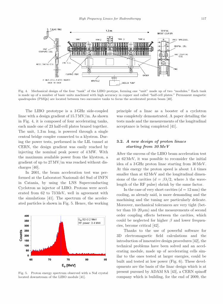
Fig. 4. Mechanical design of the four “tank” of the LIBO protype, forming one “unit” made up of two “modules.” Each tankis made up of a number of basic units machined with high accuracy in copper and called “half-cell plates.” Permanent magneticquadrupoles (PMQs) are located between two successive tanks to focus the accelerated proton beam [40].
The LIBO prototype is a 3 GHz side-coupledlinac with a design gradient of 15.7MV/m. As shownin Fig. 4, it is composed of four accelerating tanks,each made one of 23 half-cell plates brazed together.The unit, 1.3m long, is powered through a singlecentral bridge coupler connected to a klystron. Dur-ing the power tests, performed in the LIL tunnel atCERN, the design gradient was easily reached byinjecting the nominal peak power of 4 MW. Withthe maximum available power from the klystron, agradient of up to 27MV/m was reached without dis-charges [40].
In 2001, the beam acceleration test was per-formed at the Laboratori Nazionali del Sud of INFNin Catania, by using the LNS SuperconductingCyclotron as injector of LIBO. Protons were accel-erated from 62 to 73MeV, well in agreement withthe simulations [41]. The spectrum of the acceler-ated particles is shown in Fig. 5. Hence, the working
Fig. 5. Proton energy spectrum observed with a NaI crystallocated downstream of the LIBO module [41].
principle of a linac as a booster of a cyclotronwas completely demonstrated. A paper detailing thetests made and the measurements of the longitudinalacceptance is being completed [41].
3.2. A new design of proton linacs
starting from 30MeV
After the success of the LIBO beam acceleration testat 62MeV, it was possible to reconsider the initialidea of a 3 GHz proton linac starting from 30MeV.At this energy the proton speed is about 1.4 timessmaller than at 62MeV and the longitudinal dimen-sions of the cavities (d = βλ/2, where λ the wave-length of the RF pulse) shrink by the same factor.
In the case of very short cavities (d = 12mm) thecooling, as already said, is more demanding and themachining and the tuning are particularly delicate.Moreover, mechanical tolerances are very tight (bet-ter than 10–20µm) and the measurements of secondorder coupling effects between the cavities, whichcould be neglected for higher β and lower frequen-cies, become critical [42].
Thanks to the use of powerful software for3D electromagnetic field calculations and theintroduction of innovative design procedures [42], thetechnical problems have been solved and an accel-erating module, made up of accelerating cells sim-ilar to the ones tested at larger energies, could bebuilt and tested at low power (Fig. 6). These devel-opments are the basis of the linac design which is atpresent pursued by ADAM SA [43], a CERN spinoffcompany which is building, for the end of 2009, the

November 26, 2009 11:49 WSPC/253-RAST : SPI-J100 00020
118 U. Amaldi, S. Braccini & P. Puggioni
Fig. 6. Two half-cells (left) and the bridge coupler (right) of the 50-cm-long module — made up of two tanks — which acceleratesprotons from 30 to 35 MeV.
first two modules that accelerate protons from 30to 41MeV.
In the last five years the groups led by V. Vaccaroand C. De Martinis have developed a new patenteddesign of the linac plates called a back-to-back accel-erating cavity (BBAC) [44]. In the “standard” designof Fig. 6 a tank is made up of identical half-cell plateswhich exhibit a half coupling cavity on one face anda half accelerating cavity on the other face. TheBBAC design foresees instead a portion of an accel-erating cavity on one face and the complementarypart on the opposite one. The same applies to thecoupling cavity. The cutting plane is such as todivide one of the two coupling slots so that the cav-ities exhibit an asymmetric cut. Therefore one newtile is equivalent to two half-cell plates of the stan-dard design. The main advantages of this solutionare:
• The septum between two adjacent cavities is nolonger obtained by setting two tiles back to back sothat its thickness can be reduced with an increaseof the volume/surface ratio and thus of the shuntimpedance;
• The reduced number of tiles required to build atank entails a reduction of the machining and braz-ing costs.
This design was implemented in the first moduleof ACLIP, a 3GHz linac intended to accelerate pro-tons from 30 to 62MeV. The linac consists of 5 differ-ent modules for a total length of 3.1m [45]. Its firstmodule is madeup of 26 accelerating cells arranged
in two tanks. This module was built [46] and power-tested [47] with a 4 MW magnetron/modulator onthe premises of the e2v Company (UK) without anyindication that the limit of the field gradient hadbeen reached. In autumn 2009, beam accelerationtests will be performed at the Catania INFN-LNSsuperconducting cyclotron.
These two lines of activities are pursuedin Italy in collaboration with CERN, while thestudies described in Subsecs. 2.1–2.4 have beendiscontinued.
4. Standing Wave Linacs for Hadrons
To clarify the most important technical issues, onlystanding wave (SW) linacs are considered in thissection since, as discussed above, among all thedesign studies of linacs for hadrontherapy whichhave been performed so far, only one prefiguresthe use of a traveling wave (TW) structure. TWlinacs for electrons have been discussed in Vol. 1 ofReviews of Accelarator Science and Technology byP. Wilson [48].
This section is devoted to a short collection ofthe most important facts and formulae needed in thedesign of low β SW linacs, with a particular focus onCCL structures.
4.1. RF figures of merit and scaling
laws
• Transit time factor T . This measures the reduc-tion in energy gain caused by the sinusoidal timevariation of the field while the particle is transiting

November 26, 2009 11:49 WSPC/253-RAST : SPI-J100 00020
High Frequency Linacs for Hadrontherapy 119
in the gap. It approaches 1 if the gap between the“noses” of the accelerating cavities is small withrespect to βλ/2:
T =∫
E(0, z)cosωt(z)dz∫E(0, z)dz
. (2)
• Effective shunt impedance per unit of length ZTT.This measures the efficiency of producing an effec-tive axial voltage V0T for a given dissipated powerP per unit of length L:
ZT 2 =(V0T )2
P0L. (3)
• Internal quality factor Q0. This takes into accountthe lossy behavior of the resonator and is propor-tional to the number of oscillation periods neededto dissipate the energy stored in the cavity:
Q0 =ωU
P0, (4)
where ω is the resonant frequency, U the storedenergy and P0 the dissipated power. Q0 is alsorelated to the width of the resonance peak. Fora critically coupled cavity [49]:
∆H =2ω
Q0, (5)
where ∆H is the FWHM of the resonant peak andω is the resonant frequency.
The shunt impedance scales as f1/2, and the qualityfactor as f−1/2. Thus higher frequencies linacs canhave the same accelerating gradient consuming lesspower.
4.2. Figures of merit of the field
distribution
• Field nonuniformity Fnu. It is the relative standarddeviation of the fields X stored in the acceleratingcavities of a tank:
Fnu =⟨
∆X
X
⟩rms
. (6)
According to the studies of Ref. 50, this param-eter is not critical for linac operation. Errors upto ±10% can be accepted without affecting signifi-cantly the beam dynamics, provided that the aver-age tank fields, which are determined by the RFpower level, are within ±1% of the correct value.However, the requirements for therapy are morestringent. For example, in order to have a precision
of ±1mm in the 32 cm water range of 230MeV pro-tons, the mean energy of the beam must be correctwithin ±0.2%.
• Power efficiency εp. It is the ratio between the sumof the energy stored in all the accelerating cavities(effective for the acceleration) and the total energystored in the whole structure:
εp =UAC
UAC + UCC + UBC, (7)
where UAC, UCC and UBC are the sum of the ener-gies stored in the accelerating cells (ACs), couplingcells (CCs) and in the bridge coupler (BC), ifpresent, respectively.
4.3. The choice of the π/2 mode and
the stop band
In 1967, Knapp et al. [51, 52] demonstrated that theπ/2 mode has many advantages as far as the perfor-mance and the stability of the accelerator are con-cerned:
• Frequency errors of the single cavities affect thefrequency and the field distribution of the wholesystem only through second order effects;
• The losses do not produce any phase shift of theoscillations in the different cavities;
• The spacing between the working frequency and itsneighbor modes is larger than in any other mode.
Nowadays, all CCLs work in the π/2 mode, and alsonew types of accelerators take advantage of this spe-cial mode. For example, structures like SCDTL (dis-cussed in Subsec. 2.5.2) and CLUSTER (discussed inSec. 7 and in Ref. 53) can accelerate low β particleswith greater efficiency and stability than the classicalDTL.
In the π/2 mode, half of the cavities are excited(accelerating cavities, ACs) and half are not (off-axiscoupling cavities, CCs). The chain is thus biperiodic,made up of cells with two different geometries andresonant frequencies:ACsandCCs, resonating respec-tively at ωa and ωc. The stop band is the region of fre-quencies of the dispersion curve (see Fig. 7) in whichthe structure cannot be excited. It arises when the res-onant frequencies of the ACs and CCs do not match.
The stop band is closed only if the following rela-tion is satisfied:
ωa√1 − ka
=ωc√
1 − kc
, (8)

November 26, 2009 11:49 WSPC/253-RAST : SPI-J100 00020
120 U. Amaldi, S. Braccini & P. Puggioni
Fig. 7. Dispersion relation of an infinite biperiodic chain (thevertical axis is in arbitrary units). In the stop band no excita-
tion of the structure is possible.
where ka and kc are the second order coupling coef-ficient of ACs and CCs, respectively. As explainedin Refs. 51 and 52, in a circuit representation theyare proportional to the mutual inductance coefficientbetween two second neighbor cells. It can be proventhat the sensitivity of the system to frequency errorsin single cavities is proportional to the amplitude ofthe stop band. If the stop band is opened, all theadvantages of the π/2 mode vanish.
4.4. Constraints on the number of
cavities per tank
In order to minimize the length of the accelerator, toreduce the number of bridge couplers and to lowerthe power consumption, it is advantageous to have amaximum of accelerating cavities in the same tank.
The energy gain ∆W of a tank is
∆W = NcLcE0T cosφ, (9)
where φ is the stable phase [26] and Nc and Lc arethe number and the length of the cavities in the tank,respectively. The total power consumption P is givenby
P =(E0T )2NcLc
ZT 2. (10)
By combining Eqs. (9) and (10), the energy gain ina tank of length NcLc can be written in the form
∆W =√
NcLcZT 2P cosφ. (11)
Thus, for a fixed tank power consumption P , theenergy gain is proportional to N
1/2c .
However, there are constraints that have to beconsidered during the design and that limit the
number of cavities per module:
• A structure with N coupled cavities has N res-onant modes on the dispersion curve. As N
increases, the distance between the π/2 mode andits neighbors (δΩ) decreases [54] as
δΩωπ/2
= k1π
2N, (12)
where k1 is the first order coupling coefficient,which is the mutual inductance coefficient betweentwo neighbor cavities. Mode-mixing problems mayarise if the half width at half maximum ∆H isapproximately as large as δΩ. Typical values ofthe parameters in a 3 GHz CCL for β = 0.25 areQ ≈ 5000, ∆H ≈ 1.5MHz, k1 ≈ 0.05, N ≈ 65, andthus δΩ ≈ 3.5MHz.
• The field nonuniformity and the power efficiencydeteriorate with increasing N . In Refs. 51 and 52,Knapp et al. demonstrate that the field nonunifor-mity Fnu and the ratio UCC/UAC are both propor-tional to N .
4.5. Effects of tuning errors of the ACs
and the CCs
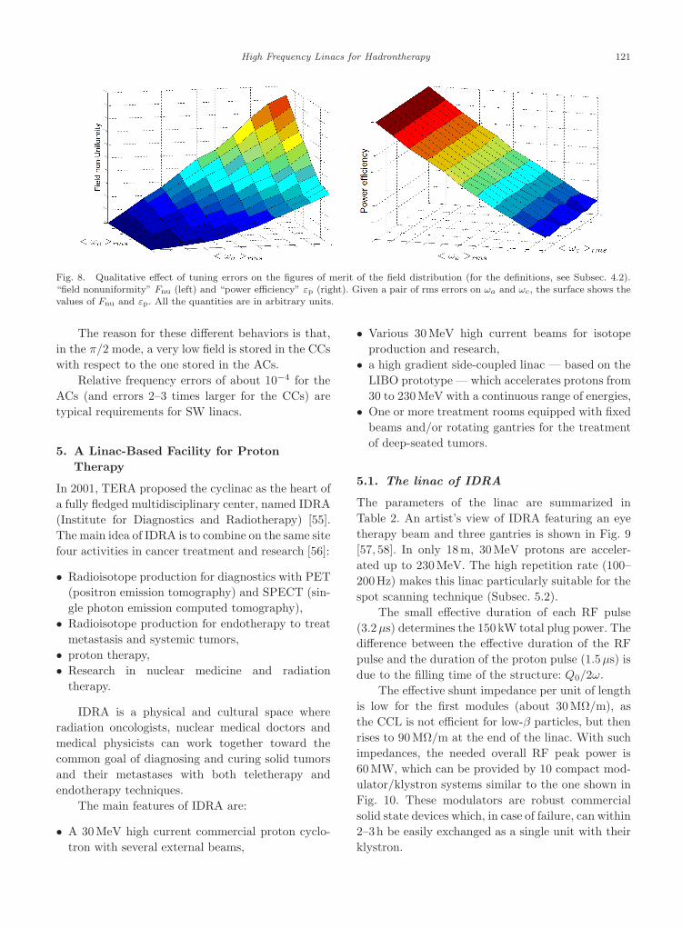
Tuning errors of the ACs and the CCs affect the fielddistribution figures of merit (defined in Subsec. 4.2).The surfaces in Fig. 8 show the values of Fnu and εp,on the left and on the right respectively, for a givenpair of rms errors of ωa and ωc.
It is seen that requirements on the precision of ωa
are more critical than those on the precision of ωc. Thepower efficiency εp is independent of the errors ofthe CCs, while it is linear in the errors of the ACs. Onthe other hand, the field nonuniformity Fnu dependson the errors of both the ACs and the CCs. However,if the rms error of the ACs is zero, even large errorsof the CCs do not change the field distribution.
An error in the resonant frequency of a CCcauses the redistribution of the energy stored in theneighbor ACs (affecting Fnu) but does not increasethe amount of energy stored in the CC itself (εp isnot affected).
On the other hand, an error on the resonantfrequency of an AC increases the field in the neigh-bor CCs (affecting εp) and, at the same time, redis-tributes the energy stored in that AC and the twoneighbor ACs (affecting Fnu).
November 26, 2009 11:49 WSPC/253-RAST : SPI-J100 00020
High Frequency Linacs for Hadrontherapy 121
Fig. 8. Qualitative effect of tuning errors on the figures of merit of the field distribution (for the definitions, see Subsec. 4.2).“field nonuniformity” Fnu (left) and “power efficiency” εp (right). Given a pair of rms errors on ωa and ωc, the surface shows thevalues of Fnu and εp. All the quantities are in arbitrary units.
The reason for these different behaviors is that,in the π/2 mode, a very low field is stored in the CCswith respect to the one stored in the ACs.
Relative frequency errors of about 10−4 for theACs (and errors 2–3 times larger for the CCs) aretypical requirements for SW linacs.
5. A Linac-Based Facility for ProtonTherapy
In 2001, TERA proposed the cyclinac as the heart ofa fully fledged multidisciplinary center, named IDRA(Institute for Diagnostics and Radiotherapy) [55].The main idea of IDRA is to combine on the same sitefour activities in cancer treatment and research [56]:
• Radioisotope production for diagnostics with PET(positron emission tomography) and SPECT (sin-gle photon emission computed tomography),
• Radioisotope production for endotherapy to treatmetastasis and systemic tumors,
• proton therapy,• Research in nuclear medicine and radiation
therapy.
IDRA is a physical and cultural space whereradiation oncologists, nuclear medical doctors andmedical physicists can work together toward thecommon goal of diagnosing and curing solid tumorsand their metastases with both teletherapy andendotherapy techniques.
The main features of IDRA are:
• A 30MeV high current commercial proton cyclo-tron with several external beams,
• Various 30MeV high current beams for isotopeproduction and research,
• a high gradient side-coupled linac — based on theLIBO prototype — which accelerates protons from30 to 230MeV with a continuous range of energies,
• One or more treatment rooms equipped with fixedbeams and/or rotating gantries for the treatmentof deep-seated tumors.
5.1. The linac of IDRA
The parameters of the linac are summarized inTable 2. An artist’s view of IDRA featuring an eyetherapy beam and three gantries is shown in Fig. 9[57, 58]. In only 18m, 30MeV protons are acceler-ated up to 230MeV. The high repetition rate (100–200Hz) makes this linac particularly suitable for thespot scanning technique (Subsec. 5.2).
The small effective duration of each RF pulse(3.2µs) determines the 150kW total plug power. Thedifference between the effective duration of the RFpulse and the duration of the proton pulse (1.5µs) isdue to the filling time of the structure: Q0/2ω.
The effective shunt impedance per unit of lengthis low for the first modules (about 30MΩ/m), asthe CCL is not efficient for low-β particles, but thenrises to 90MΩ/m at the end of the linac. With suchimpedances, the needed overall RF peak power is60MW, which can be provided by 10 compact mod-ulator/klystron systems similar to the one shown inFig. 10. These modulators are robust commercialsolid state devices which, in case of failure, can within2–3h be easily exchanged as a single unit with theirklystron.

November 26, 2009 11:49 WSPC/253-RAST : SPI-J100 00020
122 U. Amaldi, S. Braccini & P. Puggioni
Table 2. Main parameters of LIBO [58].
Accelerated particles p+1
Type of linac CCLRF frequency (MHz) 2998.5Input energy (MeV) 30
Output energy (MeV) 230Total length of the linac (m) 18.5Cells per tank/tanks per module 16/2Number of accelerating modules 20Thickness of a half cell in a tank (mm) 6.3–14.6Diameter of the beam hole (mm) 7.0Normalized transversal acceptance (mm mrad) 1.8 πNumber of permanent magnetic quadrupoles 41Length of each PMQ (mm) 30PMQ gradients (T/m) 130–153Synchronous phase (deg) −15Peak power per module (with 20% losses) (MW) 3.0Effective shunt impedance ZT 2 (inj.-extr.) 30–90
(MΩ/m)Axial electric field (inj.-extr.) (MV/m) 15–17Number of klystrons (peak power = 7.5MW) 10Total peak RF power for all the klystrons (MW) 60Klystron RF efficiency 0.42Repetition rate (Hz) ≤ 200Duration of a proton pulse (µs) 1.5Max. number of protons in 1.5 µs 4 · 107
(2 Gy L−1 min−1)Effective duration of each RF pulse (µs) 3.2RF duty cycle 3.2 · 10−4
Plug power at 100Hz + 100 kW auxiliaries (kW) 150
This accelerator complex presents many advan-tages with respect to the currently used protontherapy machines (see Sec. 8). The dose delivery can
Fig. 9. A typical layout of IDRA features a 30MeV cyclotron, a linac of the LIBO type and three treatment rooms equippedwith rotating gantries and a fixed beam line for the treatment of eye tumors [58].
naturally be performed by active methods in all threedimensions. The transversal coordinates of the beamare controlled by the use of bending magnets, whilethe longitudinal one is determined by continuouslyand rapidly varying the energy of the beam. If eachmodule is powered by one klystron, the depth of theBragg peak can be changed by selecting the numberof active klystrons and by adjusting the power sentto the last active one. Thus, as shown in Fig. 11, acontinuous range of energies is achieved and the pen-etration depth can be varied in only 2milliseconds insteps of ±1mm. This is obtained by rapidly adjustingonly the low power signals of the drivers of theklystrons.
In the design of Table 2, to reduce the numberof modulator/klystron systems, each of those powerstwo modules at the same time. This still allows oneto rapidly vary the energy in the 90–230MeV range.
5.2. Dose delivery and multipainting
techniques with protons
In radiation therapy, a ±2.5% uniform dose has to bedelivered to the tumor target. To obtain such unifor-mity using the spot scanning technique, the optimaldistance between the spots is calculated from theirnatural FWHM. As already mentioned, in the PSIspot scanning technique [2] the distance is 75% ofthe FWHM so that the dose nonuniformity is smaller

November 26, 2009 11:49 WSPC/253-RAST : SPI-J100 00020
High Frequency Linacs for Hadrontherapy 123
Fig. 10. The 7.5MW klystron is powered by a solid statemodulator commercialized by Scandinova Systems AB (Upp-
sala). LIBO employs 10 modulator/klystron sytems.
than ±1.25%. In the GSI raster scanning methodthe distance is 30% of the FWHM and the tumor ispainted only once without switching off the beam inbetween the “visits” to the 2.5 denser voxel lattice.A pulsed cyclinac beam can be used both ways in
Fig. 11. Proton depth dose distribution when the number of the active accelerating modules is varied one by one. To avoidsuperpositions a different normalization is used for each curve [58].
conjunction with a 3D feedback system, but for thetreatment of moving organs, as discussed at the endof Sec. 1, spot scanning with multipainting is pre-ferred. The reasons are that both systematic errors inthe delivered dose average out when the same voxelis visited more than 10 times and, if a spot is missing,which corresponds to a 3% drop of the local dose, theerror can be corrected during the next paintings.
At a 200mm water depth the natural lateralspread of the Bragg peak has an FWHM of 11.5mm,which, combined with a proton pencil beam hav-ing an FWHM of 7 mm, gives an overall FWHMof 13.5mm. This corresponds to a 6.4mm lateralfalloff (80%–20%), which has to be compared withthe 5.5mm “natural” value. Figure 12, taken fromRef. 58, shows the relative number of protons tobe stopped in each voxel so as to uniformly irradi-ate from a single direction and with “almost round”spots a 1L volume (diameter = 12.4mm). The num-ber of protons peaks at the distal edge, because thefront slices are crossed by the beams reaching deepervoxels. The figure is just an example, since in a realtreatment more directions will be used, in particularwhen employing the linac variable beam energy toimplement the very effective “distal edge tracking”technique (DET) [59].
A 12-times painting of a moving organ withspots containing a number of protons (adjusted

November 26, 2009 11:49 WSPC/253-RAST : SPI-J100 00020
124 U. Amaldi, S. Braccini & P. Puggioni
proton beam proton beam
Fig. 12. Number of protons (in arbitrary units) delivered in each voxel of the central transversal slice needed to obtain a ±1.25%uniform dose distribution to a 6.2-cm-radius spherical volume (1 L) centered at a 20 cm depth in water (left); number of “visits”needed to obtain a flat equivalent dose distribution with the condition with the condition that any missing visit dose not changethe total local dose by more than 3% (right). The coordinates z and x are given as a number of voxels; z is the longitudinal andx the transversal coordinate [58].
by controlling the cyclotron source) which fluctu-ate from one visit to the next by ±5% impliesa ±1.5% effect on the dose accuracy. The rightpanel of Fig. 12 shows that the proximal voxelsneed many less visits so that, on average, eachspot is painted 3.5 times [58]. Table 2 shows thatthe maximum number of protons in a spot neededto deliver, at 100Hz, the 2 GyL−1 min−1 standarddose is Nm = 4 · 107. By taking into account thelinac overall transmissions, this corresponds to a150µA current from the cyclotron, which is 3–5 timessmaller than the one routinely produced by commer-cial 30MeV cyclotrons. Of course, when sending oneof the cyclotron beams to the linac, the source will bechopped at the linac repetition rate so to minimizethe activation of the components.
6. A Linac-Based Facility for CarbonIon Therapy
In 2004, TERA designed a LIBO-like structure topostaccelerate carbon ions having 300MeV/u, suchas those produced by the superconducting cyclotrondesigned by L. Calabretta et al. of the LNS-INFNlaboratories in Catania and dubbed SCENT (Super-conducting Cyclotron for Exotic Nuclei and Ther-apy) [60, 61]. The working principle of CABOTO(CArbon BOoster for Therapy in Oncology) is sim-ilar to that of LIBO. High frequency (3GHz),high repetition rate (≤ 400Hz) and short hadron
Table 3. Parameters of the carbon ion Linac.
Accelerated particles C+1
Type of linac CCLRF frequency (MHz) 2998.5Input energy (MeV/u) 300Output energy (MeV/u) 430Total length of the linac (m) 22Cells per tank / tanks per module 15/2Number of accelerating modules 16Thickness of a half cell in a tank (mm) 15–18Diameter of the beam hole (mm) 8Normalized transversal acceptance (mm mrad) 2.8 πNumber of permanent magnetic quadrupoles 33Length of each PMQ (mm) 60PMQ gradients (T/m) 140–170Synchronous phase −15Peak power per module (with 25% losses) (MW) 4.5Effective shunt impedance ZT 2 (inj.-extr.) 100–110
(MΩ/m]
Axial electric field (inj.-extr.) (MV/m) 25–23Number of klystrons (peak power = 7.5MW) 16Total peak RF power for all the klystrons (MW) 75Klystron RF efficiency 0.42Repetition rate (Hz) ≤ 400Duration of a carbon ions pulse (µs) 1.5Max. number of C ions in 1.5 µs (2Gy L−1 min−1) 1.6 · 105
Effective duration of each RF pulse (µs) 3.2RF duty cycle 1.3 · 10−3
Plug power at 400 Hz + 100 kW auxiliaries (kW) 330
pulses (1.5µs) are the main characteristics of this22-m-long linac for carbon ions, which is particu-larly suited for the spot scanning technique withmultipainting [62].

November 26, 2009 11:49 WSPC/253-RAST : SPI-J100 00020
High Frequency Linacs for Hadrontherapy 125
The most relevant parameters of a recent ver-sion of CABOTO are collected in Table 3. It hasto be underlined that in this case the ion source isa critical component since, to obtain the maximumnumber of carbon ions in a visit Nm = 1.6 · 105, whenthe transmissions of the cyclotron and the linac aretaken into account, the source has to deliver in 1.5µsabout 1.6 ·105 fully stripped ions at 400Hz [58]. Suchintensity can be produced by the new superconduct-ing Electron Beam Ionization Sources (EBIS) pro-duced by DREEBIT GmbH (Dresden) [63].
Carbon ions can be accelerated from 300 upto 430MeV/u in a continuous range of energies byselecting the number of “active” modules and mod-ulating the energy by changing the input powerin the last active module, as already discussed forIDRA.
A scheme of the dual carbon ion and proton cen-ter designed by G. Cuttone et al. is shown in Fig. 13.The installation of the 16 accelerating modules ofCABOTO will be a second phase of the facility whichis planned for the Cannizzaro Hospital in Catania[64]. In the first phase, the 17 cm water range of300MeV/u carbon ions will allow the treatment of85% of all head and neck tumors and 80% of all lungand liver tumors [62].
Fig. 13. The hadrontherapy center designed by the Catania group is the one schematically shown on the left of the blue line.The installation of the line will allow reaching with carbon ions a water depth of 32 cm in the rooms on the right of the blue line.
It is worth noting that the carbon ion linac isshorter than the standard transport lines present inevery center to bring the hadrons from the accelera-tor to the treatment rooms.
6.1. Dose delivery and multipainting
with carbon ions
The dose delivery system is based on the spot scan-ning technique, used also for LIBO, but it has totake into account the different behavior of carbonions with respect to protons. As a matter of fact, theBragg peak produced by carbon ions is sharper andthe lateral falloff is smaller than the proton one. Forinstance, the natural FWHM of the spot producedat 20 cm by a 330MeV/u carbon beam is 3.1mm,almost 4 times narrower than that of protons hav-ing the same range. By using a pencil beam with anFWHM of 5mm, the overall transverse value of theFWHM is 5.9mm, corresponding to a 2.8mm falloff,to be compared with the 1.5mm natural one. Lon-gitudinally the FWHM is intrinsically smaller than5.9mm, but the unique property of the linac beamcomes to the rescue: by slightly varying the protonenergy, when visiting 12 times the same voxel, theBragg peak can be widened as needed. With the same

November 26, 2009 11:49 WSPC/253-RAST : SPI-J100 00020
126 U. Amaldi, S. Braccini & P. Puggioni
carbon ions beam carbon ions beam
Fig. 14. Number of carbon ions (in arbitrary units) delivered in each voxel of the central transversal slice needed to obtain a±1.25% uniform biological dose distribution to a 6.2 cm-radius spherical volume (1 L) centered at a 20 cm depth in water (left);number of “visits” needed to obtain a flat dose distribution with the condition with the condition that any missing visit dose notchange the dose by more than 3% (right). The coordinates z and x are given as a number of voxels; z is the longitudinal and x thetransversal coordinate. With respect to protons, due to the smallet FWHM of the beam, the number of spots for each dimensionis double [58].
PSI criterion adopted for proton scanning, the dis-tance between the spots is set at 75% of the overallFWHM and the number of voxels needed to coverthe 1L sphere is easily obtained.
The two histograms of Fig. 14 and the valueNm = 1.6 · 105 needed to deliver 2Gye L−1 mim−1
(Table 3) have been computed by taking into accountthe fact that the “physical dose” is different from the“equivalent dose,” which is calculated by multiplyingthe physical dose by the effective local RBE (rela-tive biological effectiveness) [65]. This semiempiricalparameter takes into account the relative effective-ness (with respect to the x-rays) of the carbon ionsin causing lethal damage to the cells. Since for car-bon ions the RBE is typically 1.5 at the beginningof the path inside the tissue and increases to about3 at the very end of the range, the physical dosedelivered to the distal slices of the tumor target hasto be lower than the one delivered in the middle inorder to obtain a “flat” equivalent dose.
7. CLUSTER, an Innovative Low β
H-Type Structure
If the linac has to accelerate carbon ions having anenergy definitely smaller than 100MeV/u, the rela-tively low shunt impedance of CCL structures impliesa further increase of the power consumption.
The need for high power efficiency in the lowβ range (0.05–0.3) leads to the choice of H-mode
accelerating cavities, also called TE cavities becausethe electric field is naturally directed transversallywith respect to the structure axis. These structureshave been studied since 1950 [66, 67] and are nowa-days used at low frequencies (100–200MHz) at GSI[68] and in Linac3 at CERN [69].
H-mode cavities are drift tube cavities operat-ing in the Hn1(0) mode, where the index n is usually1 (IH cavities; already existing) or 2 (CH cavities,under development). These cavities are very attrac-tive because of the high shunt impedance for low β
particles due to the fact that the generally trans-verse electric field is made parallel to the axis andconcentrated in the accelerating gaps by the metallicdrift tubes. Moreover, they are π-mode structures,i.e. the RF accelerating field is phase-shifted by 180
between successive gaps, a feature allowing higheraverage gradients, which in the present case are fur-ther increased by the choice of a large frequency(3 GHz).
In 2003, the TERA Foundation designed andpatented a new type of H-mode accelerator that isparticularly suitable for high frequencies and lowβ. The concept of CLUSTER (Coupled-cavity LinacUSing Transverse Electric Radial field) is to connecta certain number of H-mode tanks, by using specialbridge couplers, in a single resonant structure oper-ating in the π/2 mode, as shown in Fig. 15. Thischoice is the novelty of this design and gives greatstability to the field at these high frequencies (see

November 26, 2009 11:49 WSPC/253-RAST : SPI-J100 00020
High Frequency Linacs for Hadrontherapy 127
Fig. 15. Module of CLUSTER, the Couple-cavity LinacUSing Transverse Electric Radial field. The accelerating tank
consists of a sequence identical (constant β) accelerating units,each formed by an accelerating gap and two half drift tubes.The accelerated beam is focused by PMQs [53].
Subsec. 4.3). In order to further increase the shuntimpedance, at 3GHz the tanks consist of CH cavi-ties, while, at lower frequencies, classical IH cavitiescould also be adopted. The coupling cell of the bridgecouplers resonates in the TEM011 mode and theirgeometrical dimensions have been chosen so that thePMQs can be positioned on axis [53, 70].
In Fig. 16, the efficiency of this structure is com-pared with the approaches discussed in the previoussections. This interesting low β, high frequency andhigh shunt impedance structure can be adapted tomany applications:
(1) High current proton acceleration at 500–700MHz for radioisotope production using alinac system;
(2) Low current booster for proton therapy, to beused, for instance, in an IDRA center (see Sec. 5)that features an 18MeV cyclotron and needs alinac capable of accelerating β = 0.2 protons;
Fig. 16. Effective shunt impedance for three 3GHz linacs,with a 2.5 nm iris radius: LIBO, SCDTL, CLUSTER [53].
(3) Low current booster for carbon ions, in a centerhaving, for instance, a 60MeV/u cyclotron (k =250) as injector of the linac.
8. Linacs and Circular Accelerators:A Comparison
At present, all the hadrontherapy centers in oper-ation or under construction are based on circularaccelerators: cyclotrons and synchrotrons. For pro-ton therapy both solutions are in use and commer-cial companies offer complete centers based on oneor the other technology. On the other hand, due tothe larger energy and magnetic rigidity, synchrotronsare employed to accelerate carbon ions. Only recentlyhas it been announced that the first prototype ofa superconducting cyclotron for protons and carbonions will be built by the company IBA [71].
As far as the size is concerned, protoncyclotrons — normal or superconducting — have4–5m diameters while proton synchrotrons have6–8m diameters. For carbon ions the diameters ofthe synchrotrons are in the range 19–25m.
The beam produced by cyclotrons is character-ized by a fixed energy — usually in the range from230 to 250MeV for protons — and a 30–100MHzpulsed beam which can be considered continuouswhen compared with the human respiration period.This kind of beam is surely suited for coping with theorgan motion problem but needs a quite long specialdevice installed in the beam line — usually calledESS, for “energy selection system” — which variesthe beam energy by mechanically moving absorbersin times of the order of 100ms and, downstream ofthe absorbers, requires a set of quadrupoles, bendingmagnets and slits to select the energy and “clean”the lower energy beam. The ESS hall becomes aradioactive area due to beam losses — especiallyif 60–70MeV energies are used for eye treatments.Due to fragmentation, this system represents an evenmore critical issue for carbon ions.
The beam produced by synchrotrons is charac-terized by a spill time of about 1 s, during which thebeam is extracted for therapy, and by a filling andaccelerating time of about 1–1.5 s in which the beamis not available. From spill to spill the energy canbe varied as one wishes even if, in case of passivescattering, only a few energies are usually commis-sioned and used. It has to be noted that the beamperiodicity is similar to that of the respiration cycle,

November 26, 2009 11:49 WSPC/253-RAST : SPI-J100 00020
128 U. Amaldi, S. Braccini & P. Puggioni
Table 4. Properties of the beam of various accelerators.
Accelerator The beam The energy is Which is theis always electronically approx. time (inpresent? adjusted? ms) to vary Emax?
Cyclotron Yes No 100Synchrotron No Yes 1000Linac Yes Yes 1
which represents a disadvantage for the irradiationof moving organs with the “gating” technique.
As shown in Table 4, the beam produced bylinacs presents several advantages with respect toboth cyclotrons and synchrotrons and it can be con-sidered as optimal for applications in hadrontherapy.Linacs are in fact completely flexible in their capa-bility of varying both the energy and the intensity ofthe beam in 1–2ms.
In a cyclinac, the energy can be varied betweenthe cyclotron output value and the maximum possi-ble for the linac, but this feature will never be usedbecause of the finite momentum acceptance of thebeam transport channel. However, a ±1.5% momen-tum acceptance is sufficient to obtain a very fastadjustment ∆R of the particle range: ∆R/R ≈ ±5%.This corresponds to a longitudinal fast adjustmentof ±10mm for an R = 200mm. For deep-seatedtumors, this is more than enough to compensate forthe longitudinal variation of the particle path in thepatient’s body due to organ movements.
For tumors located at a 50–70mm depth, the±3mm fast adjustment may not be enough, but therange variation can be more than doubled by usinglarger energies and a 10 cm absorber located veryclose to the patient.
This possibility can be combined with the stan-dard use of two transverse magnetic fields and allowsthe use of a fast and electronically controlled 3D feed-back system. This system acts on the power levels ofthe last active klystron to vary the energy, and onthe intensity of the cyclotron source to adjust thenumber of particles delivered in the next spot. Theabsence of passive absorbers and mechanical devicesis surely advantageous in terms of reliability, main-tenance and radiation protection.
Particle beams accelerated by linacs have manyfeatures in common with the ones produced by (non-scaling) fixed field alternating gradients accelerators(FFAGs), which are, typically, high current acceler-ators but have recently been designed for producing
the nanoampere proton [72] and carbon ion beams[73] needed in radiation oncology. It has to be notedthat nonscaling FFAGs have not yet been built, theirRF systems are complicated and the extraction of avariable energy beam is difficult. On the contrary,high frequency linacs are very common, their RFsystems are commercial items and beam extractionposes no problem.
9. Very High Gradient Linac Structuresand Future Developments
The natural yardstick for measuring a medical linacis the 15–20m length of the ESS needed for reducingthe energy of the proton and carbon ion beamsextracted from cyclotrons. The designs of Tables2 and 3 have these lengths, and new approachesto shortening them are certainly worthwhile. More-over, if shorter linacs could be produced, one couldbuild “single room facilities” in which a proton linacrotates around the patient, as described in the patentof Ref. 74 under the name TULIP, which stands for“TUrning LInac for Proton therapy.”
The first limitation on the miniaturization ofhadron linacs is power consumption, which — fora given total acceleration voltage — increases pro-portionally to the electric field and — fixing alsothe field — is inversely proportional to the length[Eqs. (9)–(11)]. A second limitation comes from elec-tron field emission (FE) with the consequent break-down phenomena — which can locally destroy themetal surface.
In the 1950s, Kilpatrick assumed that destruc-tive breakdowns happen when FE is enhanced by acascade of secondary electrons ejected from the cath-ode by ion bombardment [75]. A simple calculationled to the Kilpatrick criterion, which states that thelimiting surface electric field increases roughly as thesquare root of the RF frequency. With the data avail-able at the time, the Kilpatrick field at 3GHz wascomputed to be Emax = 49MV/m. In the followingyears, structures were built in which the maximumsurface field was twice the Kilpatrick field.
In the last 20 years, in connection with thedesign of normal conducting electron–positron col-liders in the 10–30GHz range, many more data havebeen collected which show that (i) the phenomenaare complicated and ions do not play an importantrole [48], (ii) at 3GHz the limit is definitely larger
November 26, 2009 11:49 WSPC/253-RAST : SPI-J100 00020
High Frequency Linacs for Hadrontherapy 129
Fig. 17. The red curves represent the electric field lines ofthe accelerating mode and the arrows indicate the regions ofa typical CCL accelerating cavity where the Pointing vector Sand the electric and magnetic fields (E, H) are maximal.
than 150MV/m [76], and (iii) Emax is roughly con-stant above about 15GHz [77]. Recently, at CERN,a new quantity has been introduced — the “modi-fied Poynting vector,” [78] which has been shown todetermine the breakdown rate. This new understand-ing has opened the way to the design of shorter highfrequency linacs for hadrontherapy.
In an SW cavity such as the one in Fig. 17, theratio between the maximum field Emax and the accel-erating field in the gap can be varied in the range5–8, so that at 3 GHz accelerating gradients as largeas 30MV/m can be obtained. At larger frequenciesthe gradient can be further increased, so since 2008TERA and the CLIC RF structure group at CERNled by W. Wuensch have been collaborating on thedesign of new 9–12GHz structures.
The development of larger gradient structuresfinds its limit in the power consumption, which, for agiven repetition rate, is proportional to the durationof the RF pulse. In the case of SW linacs this dura-tion cannot be reduced below a couple of microsec-onds because of the filling time of the structure,which at 3 GHz is about 1.5µs (Subsec. 5.1). TWlinacs do not have this limitation and are thus good
candidates for short hadron linacs running at fre-quencies larger than 3 GHz.
Acknowledgments
The financial support of the Monzino Founda-tion (Milano), the Price Foundation (Geneva),the Associazione per lo Sviluppo del Piemonte(Torino) and Accelerators and Detectors for MedicalApplications — ADAM SA, Geneva — is gratefullyacknowledged.
References
[1] Particle Therapy Cooperative Group (PTCOG),http://ptcog.web.psi.ch/ptcenters.html
[2] E. Pedroni, R. Bacher, H. Blattmann, T. Bohringer,A. Coray, A. Lomax, S. Lin, G. Munkel, S. Scheib,U. Schneider and A. Tourosvsky, Med. Phys. 22, 37(1995).
[3] T. Haberer, W. Becher, D. Schardt and G. Kraft,Nucl. Instrum. Methods A 330, 296 (1993).
[4] A. M. Koelher et al., Med. Phys. 4, 297 (1977).[5] N. Kaematsu et al., Med. Phys. 29, 2823 (2002).[6] S. Webb, Intensity-Modulated Radiation Ther-
apy (Institute of Physics Publishing, Bristol andPhiladelphia, 2001).
[7] D. A. Jaffray, Semin. Radiat. Oncol. 15, 208 (2005).[8] G. Baroni, M. Riboldi, M. F. Spadea, B. Tagaste,
C. Garibaldi, R. Orecchia and A. Pedotti, J. Radiat.Res. 48, A61 (2007).
[9] T. R. Mackie et al., Med. Phys. 20, 1709 (1993).[10] www.tomotherapy.com[11] F. Lagerwaard, W. Verbakel, E. van der Hoorn, B.
Slotman and S. Senan, Int. J. Radiat. Onc. Biol.Phy. 72, S530 (2008).
[12] U. Amaldi and G. Kraft, Rep. Prog. Phys. 68, 1861(2005).
[13] H. Tsujii et al., J. Radiat. Res. 48(Suppl.), A1(2007).
[14] S. Groetzingen et al., Phys. Med. Biol. 3, 34(2008).
[15] H. Vormann, B. Schlitt, G. Clemente, C. Kleffner,A. Reiter and U. Ratzinger, Status of the linaccomponents for the Italian hadrontherapy centerCNAO, in Proc. EPAC08 (2008), pp. 1833–1835,and references therein.
[16] U. Ratzinger, G. Clemente, C. Commenda, H.Liebermann, H. Podlech, R. Tiede, W. Barth andL. Groening, A 70MeV proton linac for the FAIRfacility based on CH-cavities, in Proc. LINAC 2006(2006), pp. 526–530.
[17] A. J. Lennox, F. R. Hendrickson, D. A. Swenson,R. A. Winje and D. E. Young, Proton linac forhospital-based fast neutron therapy and radioiso-tope production. Fermi National Accelerator Lab-oratory, TM-1622 (1989).

November 26, 2009 11:49 WSPC/253-RAST : SPI-J100 00020
130 U. Amaldi, S. Braccini & P. Puggioni
[18] A. J. Lennox, Nucl. Instrum. Methods B 56/57,1197 (1991).
[19] A. J. Lennox and R. W. Hamm, A compact protonlinac for fast neutron cancer therapy, in Proc. Acc.Tech. (Long Beach, California, 1999), pp. 33–35.
[20] T. P. Wangler, Principles of RF Linear Accelerators(John Wiley and Sons, 1998), pp. 225–257.
[21] I. M. Kaochinskiy and V. A. Tepliakov, Prib. Tekh.Eksp. 2, 12 (1970).
[22] R. W. Hamm, K. R. Crandall and J. M. Potter,Preliminary design of a dedicated proton therapylinac, in Proc. PAC90, Vol. 4 (San Francisco, 1991),pp. 2583–2585.
[23] Ref. 20, p. 50.[24] M. P. S. Nightingale, A. J. T. Holmes and N. Grif-
fiths, Booster linear accelerator for proton therapy,in Proc. LINAC92 (Ottawa, 1992), pp. 398–401.
[25] J. A. Clarcke et al., Assessing the suitability ofa medical cyclotron as an injector for an energyupgrade in Proc. EPAC98 (Stockholm, 1998),pp. 2374–2376.
[26] P. Lapostolle and M. Weiss, Formulae and pro-cedures useful for the design of linear accel-erators, CERN-PS-2000-001 (2000), available athttp://preprints.cern.ch
[27] Ref. 20, pp. 209–210.[28] D. Tronc, Nucl. Instrum. Methods A 327, 253
(1993).[29] D. Tronc, Compact protontherapy unit design, in
PAC93 (1993), pp. 1768–1770.[30] D. Tronc, Patent F 91 09292.[31] D. Tronc, Patent F 92 06290.[32] D. Tronc, Patent F 93 03152.[33] U. Amaldi and G. Magrin (eds.), The Path to the
Italian National Center for Ion Therapy (Mercurio,Vercelli, 2005).
[34] U. Amaldi, The Italian hadrontherapy project, inHadron Therapy in Oncology, eds. U. Amaldi andB. Larsson (Elsevier, 1994), p. 45.
[35] U. Amaldi and G. Tosi, The hadron therapy projectthree years later. TERA 94/13, GEN 11.
[36] M. Weiss et al., The RITA Network and the Designof Compact Proton Accelerators, eds. U. Amaldi, M.Grandolfo and L. Picardi (INFN, Frascati, 1996),Chap. 9.
[37] K. Crandall and M. Weiss, Preliminary design of acompact linac for TERA. TERA 94/34, ACC 20,(1994).
[38] L. Picardi et al., Progetto del TOP Linac. ENEA-CR, Frascati (1997), RT/INN/97-17.
[39] L. Picardi, C. Ronsivalle and A. Vignati, StrutturaSCDTL. Patent No. RM95-A000564.
[40] U. Amaldi, P. Berra, K. Crandall, D. Toet, M.Weiss, R. Zennaro, E. Rosso, B. Szeless, M. Vrete-nar, C. Cicardi, C. De Martinis, D. Giove, D.Davino, M. R. Masullo and V. Vaccaro, Nucl.Instrum. Methods A 521, 512 (2004).
[41] C. De Martinis et al., Acceleration tests of a3 GHz proton linear accelerator (LIBO) for hadrontherapy. To be submitted to Nucl. Instrum.Methods A.
[42] P. Puggioni, Radiofrequency design and measure-ments of a linear accelerator for hadrontherapy,Thesis, Milano-Bicocca University (2008).
[43] www.adam-geneva.com[44] V. G. Vaccaro, Patent No 2008 A25.[45] V. G. Vaccaro et al., ACLIP: a 3 GHz side coupled
linac to be used as a booster for 30 MeV Cyclotrons,in Proc. Cycl. (2007), pp. 172–174.
[46] V. G. Vaccaro et al., Design, construction andlow power RF tests of the first module of theACLIP linac, in Proc. EPAC08 (2008), pp. 1836–1838.
[47] V. G. Vaccaro et al., RF high power tests on thefirst module of the ACLIP linac, in Proc. PAC09(2009).
[48] P. B. Wilson, Electron linac for high energy physics,in Reviews of Accelerator Science and Technology,Vol. 1, 2008, pp. 7–42.
[49] S. Turner (ed.), CAS (CERN accelerator school),Ch. 2. CERN Yellow Reports (1992).
[50] G. R. Swain, R. A. Jameson, E. A. Knapp, D. J.Liska, J. M. Potter and J. D. Wallace, IEEE Trans.Nucl. Sci. 614 (1971).
[51] E. A. Knapp, B. C. Knapp and D. E. Neagle, Rev.Sci. Instrum. 38–11, 1583 (1967).
[52] E. A. Knapp, B. C. Knapp and J. M. Potter, Rev.Sci. Instrum. 39-7, 979 (1968).
[53] U. Amaldi, A. Citterio, M. Crescenti, A. Giuliacci,C. Tronci and R. Zennaro, Nucl. Instrum. MethodsA 579, 924 (2007) and arXiv:physics/0612213.
[54] Ref. 20, p. 112.[55] U. Amaldi et al., Institute for Advanced Diagnostics
and Radiotherapy — IDRA. TERA note, 2001/6GEN 31 (July 2001).
[56] R. Zennaro, ICFA Beam Dynam. Newslett. 36, 62(2005).
[57] U. Amaldi, S. Braccini, A. Citterio, K. Crandall,M. Crescenti, G. Magrin, C. Mellace, P. Pearce, G.Pitta, E. Rosso, M. Weiss and R. Zennaro, Cycli-nacs: fast-cycling accelerators for hadron therapy,[arXiv:0902.3533v1 (2009)].
[58] U. Amaldi, S. Braccini, M. Crescenti, G. Magrin,C. Mellace, P. Pearce, G. Pitta, P. Puggioni, E.Rosso, M. Weiss and R. Zennaro, Acceleratorsfor hadron therapy: from Lawrence cyclotrons tolinacs. To be published in Nucl. Instrum. Methods A(2009).
[59] U. Oelfke and T. Bortfeld, Technol. Cancer Res.Treat. 2-5, 401 (2003).
[60] L. Calabretta and M. Maggiore, Study of a newsuperconducting cyclotron to produce a 250 MeV —50 kW light ion beams, in Proc. EPAC02 (Paris,France, 2002), pp. 614–617.

November 26, 2009 11:49 WSPC/253-RAST : SPI-J100 00020
High Frequency Linacs for Hadrontherapy 131
[61] L. Calabretta, G. Cuttonea, M. Maggiorea, M. Reaand D. Rifuggiato, Nucl. Instrum. Methods A 562,1009 (2006).
[62] U. Amaldi, Cyclinacs: novel fast-cycling accelera-tors for hadron therapy, in Proc. Cycl. 2007 (2008),pp. 166–168.
[63] G. Zschornack, F. Grossmann, V. P. Ovsyannikovand E. Griesmayer, Dresden EBIS-SC: a new gener-ation of powerful ion sources for the medical particletherapy, in Proc. Cycl. (2007), pp. 298–299.
[64] G. Cuttone, private communication.[65] M. Scholz and G. Kraft, Radiat. Prot. Dosimetry
52, 29 (1994).[66] P. Blewett, Linear accelerator injector for proton
synchrotrons, in Proc. High Energy Accelarators andPion Physics (Geneva, 1956).
[67] P. M. Zeidlitis and V. A. Yamnitskii, J. Nucl.Energy, Part C 4, (1962).
[68] U. Ratzinger, The new GSI prestripper linac forhigh current heavy ion beams, in Proc. LINAC96(CERN, Geneva, 1996), pp. 288–292.
[69] N. Angert, W. Bleuel, H. Gaiser, G. Hutter, E.Malwitz, R. Popescu, M. Rau, U. Ratzinger, Y.Bylinski, H. Haseroth, H. Kugler, R. Scrivens, E.Tankle and D. Warner, The IH linac of the CERNlead injector, in Proc. LINAC94 (Tsukuba, Japan,1994), pp. 743–746.
[70] U. Amaldi, M. Crescenti and R. Zennaro, Linac forion beam acceleration. US Patent 6888326.
[71] Y. Jongen, presented at PTCOG 47 (Jacksonville,USA, May 2008).
[72] D. Trbojevic, A. G. Ruggiero, E. Keil, N. Neskovicand A. Sessler, Design of a non-scaling FFAGaccelerator for proton therapy, in Proc. Cycl. 2004(2005), pp. 246–248.
[73] E. Keil, A. M. Sessler and D. Trbojevic, Phys. Rev.ST Accel. Beams 10, 054701 (2007).
[74] U. Amaldi, S. Braccini, G. Magrin, P. Pierce andR. Zennaro, Ion acceleration system for medicaland/or other applications. Patent WO 2008/081480A1.
[75] W. P. Kilpatrick, Rev. Sci. Instrum. 28, 824 (1957).[76] J. W. Wang and G. A. Loew, Field emission and
RF breakdown in high-gradient room-temperaturelinac structures. SLAC PUB 7684 (Oct. 1997).
[77] W. Wuensch, High-gradient breakdown in nor-malconducting RF cavities. EPAC02 (2002),pp. 134–138.
[78] A. Grudiev and W. Wuensch, A new local fieldquantity describing the high gradient limit of accel-erating structures, in Proc. LINAC08 (Victoria,Canada, 2008), pp. 936–938.
Ugo Amaldi as staff of Italian National HealthInstitute (ISS, Rome) in the 60s worked in radia-tion physics and opened two lines of research: (e,e′p)in nuclei and (e,2e) in atoms. In 1973 he movedto CERN where he co-discovered the rise of thehadronic cross-sections with energy, published thefirst paper proposing a high-energy superconduct-ing linear collider, founded and directed for 13 yearsthe DELPHI collaboration at LEP and published apaper about the supersymmetric unification of thefundamental forces, which has more than 1200 cita-tions. From the end of the 80s he has taught particleand medical physics in the two Milan Universities.In 1992 he created the TERA Foundation to designthe Italian national carbon ion facility CNAO, whichis being commissioned in Pavia, and to apply linactechnologies to hadrontherapy. More than one thirdof the Italian high-school pupils study physics on histextbooks.
Saverio Braccini is a senior physicist at the Labo-ratory for High Energy Physics of the University ofBern where he leads the research activities on medi-cal applications of particle physics. He was formerlyTechnical Director of the Foundation for OncologicalHadrontherapy TERA, where he contributed to thedevelopment of innovative accelerators and detectorsfor the treatment of tumours with hadron beams.Previously, he has been active in particle physics atthe Large Electron Positron Collider (LEP) and atthe Large Hadron Collider (LHC) at Cern, givingimportant contributions to low energy QCD and tothe construction of high precision particle detectors.
Paolo Puggioni is a young physicist graduatedin Milano-Bicocca University with Prof. U. Amaldi.In the last two years his research activity focusedon radiofrequency design, measurements and beamdynamics of low current linacs for hadrontherapy.He is a collaborator of the TERA Foundation and ofADAM SA, a CERN spin-off company in the medicalaccelerator business. At the moment he is complet-ing his postgraduate studies in Neuroinformatics atthe Edinburgh University.


![Nuclear Physics in Medicine 2013 [HADRONTHERAPY] - NuPECC](https://img.pdfslide.us/doc/110x75/613c57a3d5ddbd1b6607b8d8/nuclear-physics-in-medicine-2013-hadrontherapy-nupecc.jpg)