Embed Size (px)
Citation preview
1
SYST512
Unit 3: The Unified Software Development Process
Part 1 of 3
An Introduction
2
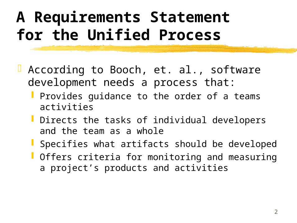
A Requirements Statement for the Unified Process
According to Booch, et. al., software development needs a process that: Provides guidance to the order of a teams activities Directs the tasks of individual developers and the
team as a whole Specifies what artifacts should be developed Offers criteria for monitoring and measuring a
project’s products and activities

3
The Unified Process: A Snapshot
The unified process is made of components connected via well defined interfaces Based on the Unified Modeling Language (UML) Use Case Driven, Architecture-centric, Iterative and
Incremental

4
Use Cases
A Use Case can be defined as a piece of functionality that gives a user a result of value Sum of all use cases form the use case model
Use cases capture functional requirements - replace the traditional functional specification

5
Architectures
Booch, et. al. describe an architecture as the different views of the system being built
Embodies the most significant static and dynamic aspects of the system Influenced by platform, operating systems, DBMS, etc. View of the whole design with the important characteristics
mode more visible by leaving the details aside
6
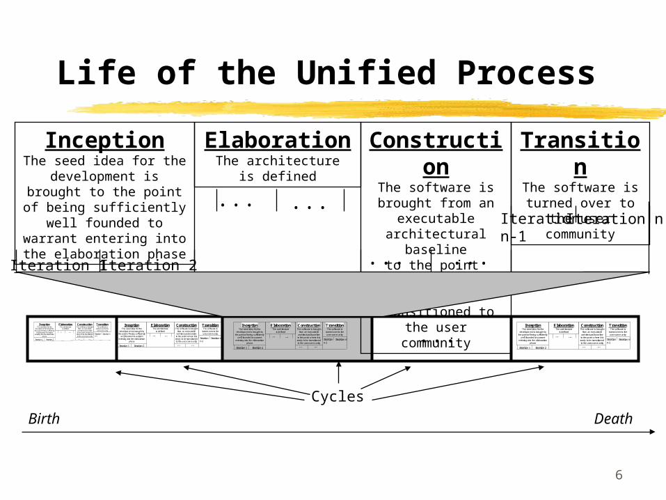
Life of the Unified Process
Birth Death
Cycles
InceptionThe seed idea for the
development is brought to the point of being sufficiently
well founded to warrant entering into the elaboration
phase
ElaborationThe architecture
is defined
ConstructionThe software is brought
from an executable architectural baseline
to the point where it is ready to be transitioned to the user community
TransitionThe software is
turned over to the user community
Iteration 1 Iteration 2
... ...
... ...
Iteration nIteration n-1
InceptionThe seed idea for the
development is brought tothe point of being sufficiently
well founded to warrantentering into the elaboration
phase
ElaborationThe architecture
is defined
ConstructionThe software is brought
from an executablearchitectural baselineto the point where it isready to be transitionedto the user community
TransitionThe software is
turned over to theuser community
Iteration 1 Iteration 2
... ...
... ...
Iteration nIteration n-1
InceptionThe seed idea for the
development is brought tothe point of being sufficiently
well founded to warrantentering into the elaboration
phase
ElaborationThe architecture
is defined
ConstructionThe software is brought
from an executablearchitectural baseline
to the point where it isready to be transitionedto the user community
TransitionThe software is
turned over to theuser community
Iteration 1 Iteration 2
... ...
... ...
Iteration nIteration n-1
InceptionThe seed idea for the
development is brought tothe point of being sufficiently
well founded to warrantentering into the elaboration
phase
ElaborationThe architecture
is defined
ConstructionThe software is brought
from an executablearchitectural baselineto the point where it isready to be transitionedto the user community
TransitionThe software is
turned over to theuser community
Iteration 1 Iteration 2
... ...
... ...
Iteration nIteration n-1 ...

7
Core Work Flows
CoreWorkflows
Inception Elaboration Construction Transition
Requirements
Analysis
Design
Implementation
Test

8
Unified Process Models
Use Case ModelModels Use Cases and their relationships to users
Analysis ModelRefines the use cases and makes an initial allocation of behavior to set of objects
Design ModelDefines the static structure of the system as subsystems, classes and interfaces and defines the use cases as collaborations of subsystems, classes and interfaces Implementation
ModelIncludes components (representing source code) and the mapping of classes to components
Deployment ModelDefines the physical nodes of computers and the mapping of the components to those nodes
Test ModelDescribes the test cases that verify the use cases
specified by verified by
realized by distributed by
implemented by

9
The Four Ps in Software Development - People, Project, Product and Process
People - The architects, developers, testers and the supporting management, users, customers, and stakeholders - Actual Humans!
Project - The organizational element through which software is managed.
Product - Artifacts that are created during the life of the project, e.g., models, source code.
Process - A definition of the complete set of activities needed to transform users’ requirements into a product. A process is a template for creating projects. Tools - Software that is used to automate the activities defined in the
process.

10
Resources and Workers
People are resources Worker is a position that a person is assigned and they
accept Worker types is a role that an individual may play in software
development, e.g. use case specifier Workers are responsible for a set of activities A worker may be realized by a set of individuals working
together A resource may be many workers during the development of the
software

11
Software Systems and Artifacts
A software system is composed of all the artifacts that it takes to represent it to the machines, workers and stakeholders
An artifact is a general term for any kind of information created, produced, changed or used by workers in developing the system Artifacts include UML diagrams and their associated text, user-interface
sketches and prototypes Management artifacts include business case for the system, allocation
of resources to workers and specification of development environment

12
Process and Projects
Process is a definition of a set of activities, not their execution A process instance is a project
A process is composed of workflows where a workflow is a set of activities
To create a work flow Identify the workers Identify the artifacts Identify the relationships between workers and artifacts
Activity diagrams and swim-lanes (p.25) show how work flows from worker to worker

13
Process Merits
The process can be modified to accommodate organizational factors, domain factors, life cycle factors and technical factors
Everyone on the development team understands their responsibilities Developers can better understand what other developers are doing Supervisors and managers who may be code illiterate can understand what
the developers are doing Developers, supervisors and managers can transfer between projects and
divisions without having to learn a new process Training can be standardized within a company and obtained from colleges
and short courses. The course of software development is repeatable.

14
Tools Are Essential for Development
Requirements Management - Store, browse, review, track and navigate the requirements for a software project.
Visual Modeling - Used to automate the use of UML (or other modeling languages!) and assemble an application visually. Integrate with programming environments and ensure that the model and implementation are consistent.
Programming tools - Used to provide a range of tools to include editors, compilers, debuggers, error detectors and performance analyzers.
Quality Assurance - Used to test applications and components, i.e., to execute test cases and regression test.

15
A View Into Use Cases ( 1 of 4)(From UML Language User Guide)*
A Use Case describes as set of sequences, in which each sequence represents the interaction of the things outside the system (its actors) with the system itself (its key abstractions). These behaviors are in effect system level functions used to visualize, specify, construct and document the intended behavior of the system during requirements capture and analysis. A use case represents a functional requirement of the system as a whole.
*Booch, Jacobson, Rumbaugh, Addison-Wesley 1999

16
A View Into Use Cases (2 of 4)
Use cases involve the interaction of actors and the system. Actors can be human or automated systems.
Use cases can have variants, particularly specialization, composition and behavioral extension.
Use cases can be applied to the system as a whole or subsystems.Applied to subsystems they are useful for regression testingApplied to system as a whole they are useful for integration
and system testing

17
A View Into Use Cases (3 of 4)
Each use case must have a unique name Typically represented as an oval with the name inside
An actor represents a coherent set of roles that users play when interacting with the user Connected to use cases only by association Can be specialized Typically represented as a labeled stick figure
Behavior of a use case is described by a flow of events in textual format Include how and when use case starts and ends When use case interacts with actors What objects are exchanged Exceptions

18
A View Into Use Cases (4 of 4)
Scenarios are to Use Cases as instances are to classes Represents one possible flow through all of the variations described by the use
case
To model the behavior of an element (i.e., system or subsystem) Identify the actors that interact with the element. Organize the actors by identifying general and more specialized roles For each actor, consider the primary ways in which the actor interacts with the
element Consider also the exceptional ways in which each actor interacts with the element Organize these behaviors as use cases, applying include and extend relationships
to factor common behavior and extend exceptional behavior.
19
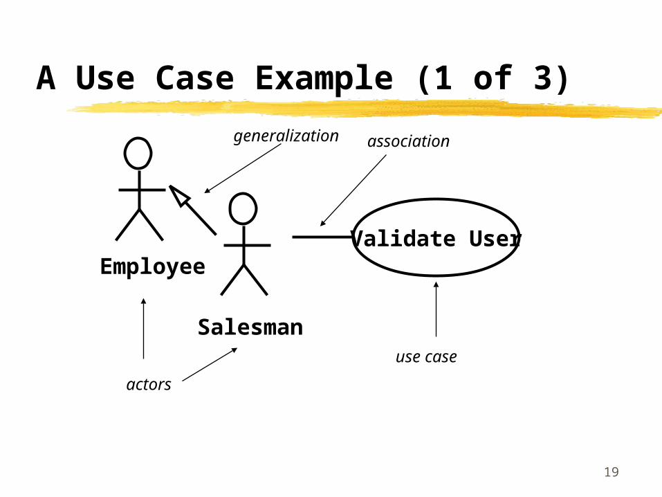
A Use Case Example (1 of 3)
Validate User
Salesman
Employee
actors
use case
generalization association

20
A Use Case Example (2 of 3) (Adapted from UML Language User Guide)*
Flow of Events Main flow of events: The use case starts when the system prompts the
salesman for a password. The salesman can now enter a password via the keypad. The salesman commits the entry by pressing the Enter button. The system then checks the password to see if it is valid. If the password is valid, the system acknowledges the entry, thus ending the use case.
Exceptional flow of events: The salesman can cancel a transaction at any time by pressing the cancel button, thus restarting the use case. No changes are made to the salesman’s account.
Exception flow of events: The salesman can clear a password anytime before committing it and reenter a new password.
*Booch, Jacobson, Rumbaugh, Addison-Wesley 1999

21
A Use Case Example (3 of 3) (From UML Language User Guide)*
Validate User
TrackOrder
Place OrderExtension points
set priority
Place RushOrder
Retinal Scan
Check Password
*Booch, Jacobson, Rumbaugh, Addison-Wesley 1999
<<include>>
<<include>>
<<extend>>(set priority)
generalization

22
Why Use Cases?
Use cases provide a systematic and intuitive means of capturing functional requirements
Use cases drive the development process since most activities such as analysis, design and test are performed starting from use cases.
Ties functionality to users (actors) Focuses the analysis and reduces specification of superfluous
functionality
Use cases are simple to read Facilitates reaching an agreement with customers and users

23
The Need for Software Architectures
Software architectures are needed to: Understand often large technologically complex systems which
combine distributed computing, COTS and reusable components which result in complex behavior
Organize development to result in reduced communications between geographically distributed entities
Foster use of reusable components Design the system for evolution

24
Software Architectures
Software architectures encompass the significant decisions about: The organization of a software system The structural elements and their interfaces that will comprise
the system, together with their behavior as specified in the collaborations among those elements
The composition of the structural and behavioral elements into progressively larger subsystems
The architectural style that guides the organization: the elements and their interfaces, their collaborations and their composition

25
Architectural Concepts
Architectures are specified in an architectural description
An architecture is developed iteratively during the elaboration phase through requirements, analysis, design, implementation and test
The architecture description is a view into the models of the system
26
The Architecture Description
The architecture is represented by views into the various models Contains five sections, one for the use case model,
the analysis model (often not maintained), the design model, the deployment model and the implementation model
No view into the test model as it has no role in describing the architecture and used to verify the architecture baseline only

27
Architectural Views The architectural view of the use-case model presents the most
important actors and use-cases The architectural view of the design model presents the most
important subsystems, interfaces and a few very important classes The architectural view of the deployment model defines the
architecture in terms of connected nodes, hardware units that the software components can execute on
The architectural view of the implementation model is a straightforward mapping from the design and deployment model - each design service subsystem results in one component that is installed on a node

28
Architectural Influences
System Software
Middleware
Legacy Systems
Standards and policies
Nonfunctional Requirements
Distribution needs
Use Cases
Architecture
Experience•Previous Architectures•Architectural patterns
Constraints and enablers
29
What Is Not Architecture
Most classes, with operations, interfaces and attributes that are private to subsystems
Subsystems that are variants of other subsystems
Most Use Case realizations Information needed to validate or verify the
architecture

30
Architectural Patterns
A pattern is a solution to a commonly occurring design problem A general collaboration that can be specialized as defined
by a template Architectural patterns focus on larger grained structure and
interactions of subsystems and systems (e.g., broker, client server, peer-to-peer)
Layered architecture has individual subsystems at various layers (a set of subsystems that share the same degree of generality and volatility)

31
SYST512Unit 3: The Unified Software Development Process
Part 2 of 3Requirements Capture and Workflow
32
Requirements Capture Defined Requirements capture can be defined as the process of finding out
what needs to be built Achieved by describing the system requirements well enough so that an
agreement can be reached between the customer and the system developers
Aka Jacobson et. al. “it is absurd to believe that the human mind can come up with a consistent and relevant list of thousands of requirements of the form “The system shall…””
The users often do not understand what the system ought to do until the system is completed Jacobson suggests that believing that users know what the
requirements are can be incorrect
33
Requirements Capture Overview (1 of 2)
List Candidate Requirements Over the life of the system Metadata includes status, estimated cost to implement, priority,
associated risk
Understand System Context Domain modeling describes the important concepts as domain objects
and links the objects to another Business modeling describes existing and perceived processes and
which processes are to be supported by the system
Capture Functional Requirements use-case based - each use-case represents one way of using the
system Also specify what the user interface looks like

34
Requirements Capture Overview (2 of 2)
Capture Nonfunctional Requirements Generally refers to constrains, “ilities” such as maintainability, reliability,
extensibility Connected as tagged values to the use-cases Some nonfunctional requirements cannot be tagged to a particular use-
case and should be maintained on a list of supplementary requirements
Traditional requirements specification is replaced by a the use-case model and a list of supplementary requirements
35
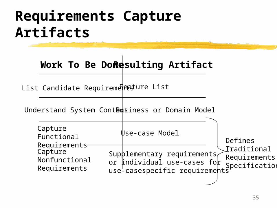
Requirements Capture Artifacts
Work To Be Done Resulting Artifact
List Candidate Requirements
Understand System Context
Capture Functional Requirements
Capture Nonfunctional Requirements
Feature List
Business or Domain Model
Use-case Model
Supplementary requirementsor individual use-cases for use-casespecific requirements
DefinesTraditionalRequirementsSpecification

36
Distribution of Requirements by Phase
CoreWorkflows
Inception Elaboration Construction Transition
Requirements
Analysis
Design
Implementation
Test
~10% ~80% ~10%

37
Domain Models (1 of 2)
Domain Models consist of business objects, real-world objects, events that will or have transpired, e.g. ….
1..*
1..*
buyer
seller
1
1
balanceowner
Account
itemDescriptionpicturecost
accountdate of submissionlast date of payment
Invoice
Order
Date of submissiondelivery address
payable

38
Domain Models (2 of 2)
Modest domains usually require between 10 and 50 classes
The purpose is not to model system internals but to contribute to an understanding of the system’s requirements as the originate from context
39
Business Models (1 of 4)
Goal is to understand the system by understanding the business processes Can model the the system encompassing the software system that is being
developed
Describes the business processes of a company in terms of business use-cases and business actors
Described in terms of use-case diagrams Business-object is an interior model of the business Business-entity represents something which workers access, inpsect,
manipulate, produce or use in a business case A work unit is a set of buiness entities that forms a recognizable whole to
the end use

40
Business Models (2 of 4)
Business models are developed by first preparing a business use-case model that identifies the actors to the business and the business use-cases that the actors use.
Secondly, a business object model is developed which consists of workers, business entities and work units that realize the business use-cases.
Business models differ from domain models in three primary ways Domain classed are pulled out of the knowledge base of a few domain
experts while business entities are derived by starting from the customers of the business, identifying the business use-cases and the finding the entities

41
Business Models (3 of 4)
Business models differ from domain models in three primary ways (cont.) Domain classes have attributes but few if any operations. Business
modeling identifies the workers that will participate by using the entities and through the operations that the entities will provide
Workers found in business modeling are used as a starting point to derive a first set of actors and use-cases for the information system to be built.
To derive use-cases from business models Identify the system actors for every worker and business actor
(customer)
42
Business Models (4 of 4)
To derive use-cases from business models (cont.) Identify all the business use-case realizations in which each worker
participates Find use-cases for the system actors of the information system Identify a tentative set of use-cases by creating a use-case for each
corresponding actor for each role of each worker and business actor
43
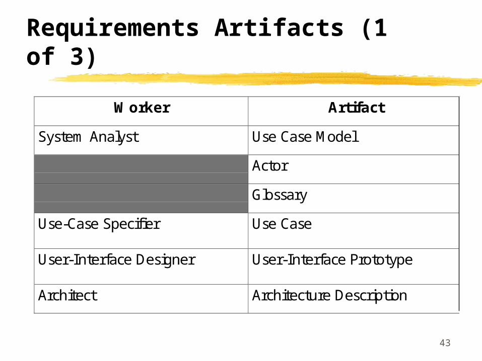
Requirements Artifacts (1 of 3)
Worker Artifact
System Analyst Use Case Model
Actor
Glossary
Use-Case Specifier Use Case
User-Interface Designer User-Interface Prototype
Architect Architecture Description

44
Requirements Artifacts (2 of 3)
Use-case model provides the functional model of the system containing actors, use-cases and their relationships Actors are all parties (human and automated) that collaborate with the system -
plays one role for each use-case that it collaborates with Use-cases specify a sequence of actions, including alternatives to the sequence,
that the system can perform Use-cases have operations and attributes - thus a use-case description can
include state chart diagrams, collaborations and sequence diagrams Use-case attributes represent the values that a use-case instance uses and
manipulates Use-case instances do not interact with other use-case instances - reason is that
use-case models should be simple and intuitive The flow of events and special requirements are captured in special textual
descriptions

45
Requirements Artifacts (3 of 3)
Architecture description contains a view of the use-case model depicting the architecturally significant use cases
Glossary defines important and common terms used by analysts when they describe the system - tends to be focused on the system to be built as opposed to the context
The user-interface prototype helps understand and specify the interactions between the human actors and the system

46
Four Workers Involved In Use-Case Modeling
System Analyst is responsible for all requirements modeled as use-cases, use-case specific non-functional requirements, finding the actors and ensuring consistency as well as structuring the use-case model Not responsible for individual use-cases One system analyst for each system
Use-Case Specifiers take the responsibility for the detailed descriptions of one or more of the use-cases, working closely with intended users of the system
User-Interface Designers create user interfaces specified by use-cases Architects prioritize the use-cases to describe architectural view of the use-
case model

47
Requirements Capture Workflow Overview
Find Actors and Use Cases
Prioritize Use Cases
Structure the Use-Case Model
Detail a Use Case
Prototype User-Interface
System Analyst
Architect
Use-Case Specifier
User-Interface Designer

48
Find Actors and Use Cass
Purpose To delimit the system from its environment Outline who and what actors will interact with the system and what functionality
is expected from the system Capture and define a glossary of common terms that are essential for creating
detailed descriptions of the systems functionality
Business or Domain Model
SupplementaryRequirements
Feature ListFind Actors and Use-Cases
System Analyst
Use-Case Model Outlined
Glossary

49
More On Finding Actors and Use-Cases (1 of 2)
If a business model exists, a one to one mapping between actors and workers and business actors
It should be possible to find at least one user per candidate actor There should be a minimum of overlap between the roles that instances of the
different actors play in relation to the system As a starting point, a use-case is suggested for every role of each worker or each
actor in supporting the work to create, change, track, remove or study business objects Some initial use-cases may become parts of other use-cases
Each successfully performed use case should provide some value to the actor such that the actor achieves some goal. As discussed, use-cases should be tied to a particular actor.
Segments of the use-case model can be organized into use-case packages

50
More On Finding Actors and Use-Cases (2 of 2)
A use-case model is reviewed to ensure that all necessary functional requirements have been captured as use-cases, the sequence of actions is correct, complete and understandable for each use-case and use-cases that have minimal value have been identified Use cases are prioritized Flow of events within a use case can be described as state transitions
State State(e.g. paid)
State
Start Stop
Transitions
Transition description (e.g., pay invoice)

51
What to Include in Use-Cases
Define the start state How and when the use-case starts Required order of actions performed How and when the use-case ends Possible end states of the use-case Paths of execution that are allowed and not allowed Alternative path descriptions that have been extracted System interactions with the actors and what they exchange Usage of objects, values and resources in the system Use-case instances that access other use-case instances attributes are forbidden Non-functional requirements are tagged Protocols for interactions with other systems A use-case description is finished when it is deemd understandable, correct, complete and
consistent with other descriptions

52
Creating Logical User-Interface Design For each actor, user interface issues can be driven by the following:
Determine which user interface elements are needed to enable the use-cases and their relationships
How should they look and be manipulated and how do they differ from each other
Which of the domain classes, business entities or work units are suitable as user-interface elements for the use-case?
What user-interface elements doe the actor work with? What actions can the actor invoke and what decision can he make? What guidance and info does the actor need before invoking the actions in the
use case What info does the actor need to supply to the system? What info does the actor need to supply to the system What are the average values for all input/output parameters? Consider essential use-case modeling a la Constantine.

53
Structuring the Use Case Model
Extract general and shared use-case descriptions of functionality that can be used by more specific use-case descriptions Generalization between use-cases is a kind of inheritance - use-cases can perform all
behavior described in the generalizing use-case Complete use-cases are concrete Abstract use-cases can be instantiated and reused
Extract additional or optional use-case descriptions of functionality that can extend more specific use-case descriptions An extend relationship models additions to a use case’s sequence of actions Extend relationships model the condition(s) for extension and the extension
point, I.e., the position in the use-case where the extension can be made Can view the include relationships as a reversed extend relationship that provides
explicit and unconditioned extensions to a use-case

54
Requirements Workflow Summary
Requirements capture can be viewed as: A business model or a domain model to set the context of the
system A use-case model that captures the functional and non-
functional requirements that are specific to individual use-cases A set of user interface sketches and prototypes for each actor
representing the design of the user interfaces A supplementary requirements specification for the
requirements that are generic and not specific for a particular use-case