Embed Size (px)
Citation preview
1
Surface Reconstruction via FusingSparse-Sequence of Depth Images
Long Yang, Qingan Yan, Yanping Fu, and Chunxia Xiao
Abstract—Handheld scanning using commodity depth cameras provides a flexible and low-cost manner to get 3D models. Theexisting methods scan a target by densely fusing all the captured depth images, yet most frames are redundant. The jittering framesinevitably embedded in handheld scanning process will cause feature blurring on the reconstructed model and even trigger the scanfailure (i.e., camera tracking losing). To address these problems, in this paper, we propose a novel sparse-sequence fusion (SSF)algorithm for handheld scanning using commodity depth cameras. It first extracts related measurements for analyzing camera motion.Then based on these measurements, we progressively construct a supporting subset for the captured depth image sequence todecrease the data redundancy and the interference from jittering frames. Since SSF will reveal the intrinsic heavy noise of the originaldepth images, our method introduces a refinement process to eliminate the raw noise and recover geometric features for the depthimages selected into the supporting subset. We finally obtain the fused result by integrating the refined depth images into the truncatedsigned distance field (TSDF) of the target. Multiple comparison experiments are conducted and the results verify the feasibility andvalidity of SSF for handheld scanning with a commodity depth camera.
Index Terms—depth image refinement, handheld scanning, sparse-sequence fusion, surface reconstruction, supporting subset.
�
1 INTRODUCTION
COMMODITY depth cameras (e.g., Microsoft Kinect [1])open up a new way to capture 3D models. Unlike
the conventional optical scanner with special scanning set-up [2], [3], commodity depth cameras make 3D scanningflexible and accessible to general users with low-cost [4], [5].Especially, the handheld scanning manner could capturethe models which are inconvenient to be scanned by afixed scanning platform because of their weight, volume orspecial position. For example, the big and heavy Stanfordsculpture group in [6], the relief on a large wall (Fig. 12)and a tree-trunk (Fig. 9) could be reconstructed by handheldscanning using a commodity depth camera.
Following the fundamental pipeline of 3D reconstructionfrom range images, KinectFusion [7] takes frame-to-modelregistration to align an input depth image and incrementallyintegrates the aligned depth images into the fused target.Since the registration and fusion computations are loadedon GPU, KinectFusion makes real-time handheld scanningwith commodity depth cameras feasible and obtains impres-sive reconstructed results. Users can hold a depth cameraand roam around a target to get its 3D model [8], [9].Handheld scanning by commodity depth cameras is expect-ed to provide abundant 3D models for computer graphicscommunity. Recently, a number of research works acquire3D objects or scenes using commodity depth cameras basedon Kinectfusion [8], [9], [10], [11], [12], [13], [14].
Although handheld scanning with commodity depth
• L. Yang is with the Computer School, Wuhan University, Wuhan, Hubei430072, China, and the College of Information Engineering, NorthwestA&F University, Yangling, Shaanxi 712100, China.E-mail: [email protected].
• Q. Yan, Y. Fu, and C. Xiao are with the State Key Lab of Software En-gineering, Computer School, Wuhan University, Wuhan, Hubei 430072,China.E-mail: {Yanqingan, ypfu, cxxiao}@whu.edu.cn.
cameras has made large progress in terms of its flexibilityand the real-time performance, it still contains some draw-backs. The bottlenecks mainly exist in two aspects: (1) Alarge number of redundant depth images are incorporatedinto the data fusion. To scan a moderate size object, it hasto integrate nearly a thousand frames which are mostlyunnecessary. (2) The jittering frames of handheld scanningmight blur the geometric features of a scanned surface andeven trigger the failure of camera tracking. An example isshown in Fig. 1(a), where the geometric features on thereconstructed model are smoothed and even the face isdistorted.
KinectFusion scans a target with the high frame-ratefor successive visual tracking. Densely fusing all the cap-tured frames benefits denoising a single depth surface, butit involves heavy scene redundancy between consecutiveviewpoints. Since the assumption of low-speed and stablecamera motion [15] cannot be guaranteed for handheldscanning and the fusion will be reset once the cameratracking fails, in practice, users have to try many times tofinish scanning an object. So far as we know, there is noexisting work which attempts to cut down the redundantframes and generate pleasing results for handheld scanningby using commodity depth cameras.
In this paper, we present a new sparse-sequence fusion(SSF) algorithm, which is based on the extracted supportingsubset from the captured depth image sequence, for hand-held 3D scanning with commodity depth cameras. A unifiedobjective function is devised to screen out the supportingdepth images meanwhile filter both redundant and jitteringframes. In addition, we introduce a refinement operationfor the selected depth images. This refinement benefits thereconstructed result of SSF. The main contributions of thispaper include:
2
(a) dense-sequence fusion (b) sparse-sequence fusion
Fig. 1. Depth sequence fusion of handheld scanning with a commodity depth camera. In (a), the left-top is the input depth image sequence, theleft-bottom is camera trajectory of dense-sequence fusion, the right part is the reconstructed surface of dense-sequence fusion. The counterpartsin (b) are sparse depth sequence, camera trajectory of SSF and the corresponding reconstruction result, respectively.
• Proposing a unified objective function to constructthe supporting subset. We extract several effectivemeasurements to describe the dynamic state of came-ra motion. The sparse expression problem of originaldepth sequence is solved by the online analysis ofthese measurements.
• Eliminating the dependence of dense-sequence fu-sion by introducing a refinement process for theselected depth images. It denoises depth images inthe supporting subset meanwhile recovers their geo-metric features.
The remainder of this paper is organized as follows:Section 2 describes the related work of 3D reconstructionfrom range images. We give the overview of our algorithmin Section 3. The details of surface reconstruction fromSSF and its implementation are elaborated in Sections 4and 5, respectively. Section 6 shows the experiments anddiscussions. Finally, we conclude our work in Section 7.
2 RELATED WORK
Reconstructing 3D model from multi-view range images hasbeen widely investigated in the last two decades [16], [2], [3].Herein we will review the related work about range scan,fusion and enhancement of the coarse depth images, andthe recent progress in 3D scanning by commodity depthcameras.
The general 3D optical scanning technique contains threeprocedures. It first captures surface segments correspondingto the consecutive-view depth images, and then registersthese segments to a unified world coordinate system, finallyintegrates and fuses these aligned surfaces to reconstruct thetarget model.
Registering multiple depth images is the basis of 3Dscanning [3], [17], [18]. Iterative closest point (ICP) algo-rithm [19] aligns two scanned segments (i.e., estimates the
variation of camera pose) via iteratively updating point-pairs and minimizing the sum of distances between all thepoint-pairs. KinectFusion uses Point-to-plane ICP [20] to im-prove the efficiency of registration. Moreover, it replaces thetraditional frame-to-frame camera tracking with the frame-to-model manner, which aligns the current frame with aprojected depth image on the last camera pose from thefused model. Since each referenced depth image is projectedfrom a gradually completed unique model, frame-to-modelregistration could effectively reduce the drift artifact andprovide a reliable estimation of camera pose for an indoor-scale scene [7], [21]. Nevertheless, the jittering frames indepth image sequence of handheld scanning will cause thefailure of camera pose tracking.
Surface integration aims to remove the crack, overlapand deficiency of the aligned segments and generate a nicemodel. The earlier work [22] stitches multiple segmentsbased on the Venn diagram. The method [23] clips thesegments along their boundaries and merges them to be acomplete mesh surface. KinectFusion employs volumetricrange image processing (VRIP) [16] to fit the overlappedsegments and utilizes the truncated signed distance field(TSDF) to represent the fused surface. Since the scannedtarget is embedded in a bounded volumetric space whichis encoded with the TSDF of the fitted surface, it couldupdate the implicit representation of target surface readilyand reconstruct complex models robustly. However, it lacksscreening mechanism for original depth images. Fusing theredundant frames and the jittering depth images will blurgeometric features of the scanned target.
A single range surface acquired by a commodity depthcamera inherently contains heavy noise [24]. Existing 3Dscanning methods using commodity depth cameras elimi-nate noise via fusing the dense depth-image sequence [7].There are several ways to enhance the surface segment of asingle depth image. Most up-sampling methods [25], [26]could refine a coarse and low-resolution depth image
3
by interpolating depth-pixels under the guidance of ahigh-resolution RGB image. Shading based depth refine-ment [27], [28], [29] employs the shading decomposition ofan aligned RGB image to enhance the corresponding depthimage. It requires a reliable estimation for both illuminationand albedo. It is infeasible to integrate these techniquesinto the real-time procedure of handheld scanning, sincethe unstable camera motion might cause blur artifacts onRGB images and precisely estimating albedos for differentparts of a scene is intractable. A multi-scale method [30],which recovers geometric features without the assistance ofan additional RGB image, could be adapted to refine thedepth images captured by commodity depth cameras.
Relying on the mobility of commodity depth camera,together with the simultaneous localization and mapping(SLAM) technique on dense depth map [31], depth im-age fusion has been extended to large-scale scenes bymeans of translating and rotating the integrated TSDFcube [15], [9], [10]. Chen et al. [11] employ a hierarchicalGPU data structure which compresses the generated TSDFvolume to reconstruct large-scale scene with real-time highquality. Nießner et al [12] exploit voxel hashing rather thanregular grid to efficiently access and update the implicitsurface for large-scale scene. The saved time is then usedfor increasing ICP iterative times so that it improves theregistration accuracy and generates faithful surfaces.
To scan a large scene reliably, the inevitable drift artifactof camera tracking should be well controlled. Zhou et al. [6]distribute the accumulated errors of the camera pose tothe non-interesting parts so that the interesting regions willbe reconstructed faithfully. The elastic fragment fusion [13]exploits non-rigid fusion between adjacent volumes to gen-erate global consistent 3D scene. Fioraio et al. [14] reducecamera drift by updating the associated TSDFs betweentwo adjacent sub-volumes. Recently, Xu et al. [32] explorethe direction of automatic robot scanning via online sceneanalysis based on KinectFusion. Zhang et al. [33] integratestructural information from online analysis to enhance thereconstruction of indoor scenes. These methods have not in-vestigated scanning reconstruction from sparse depth imagesequence. The aforementioned two drawbacks of handheldscanning in Section 1 still exist. Without decimating thecaptured depth images, more redundant frames need to besaved and fused when a large-scale scene is scanned.
Unlike the existing approaches, our method exploressurface reconstruction via SSF for handheld scanning 3Dobjects using a commodity depth camera.
3 OVERVIEW
3.1 Problem StatementThe basic setting of our problem is handheld scanningusing a commodity depth camera. Our goal is to realize 3Dreconstruction of SSF. The core problem is how to decreasethe redundant depth images and simultaneously excludethe jittering frames from the original sequence. Moreover,SSF will reveal heavy noise of the raw depth images. Weshould generate noise-free results in spite of using lessdepth images.
Supporting subset. To achieve SSF, we exploit a support-ing subset to represent the original depth image sequence.
We do not intend to give a mathematical definition of thesupporting subset. But its essential properties are provided.It should effectively decouple the supporting depth images,the jittering frames, as well as the redundant frames. Thesupporting subset should cover all views of the scannedtarget included in the original sequence. Our supportingsubset will balance between the sufficiency of scanning viewand the sparseness of original sequence.
Single-frame refinement. Dense fusion removes theheavy noises of the raw depth images relying on abundantlyaveraging the target’s TSDF [7]. Sparse fusion integrates on-ly a few depth images so that the reconstructed model willbe noise-contaminated. We introduce a refinement processto improve the quality of each selected depth image in thesupporting subset. It will break the dependence of dense-sequence fusion. With the refined depth images, SSF doesnot depend on dense fusion to eliminate noise anymore.
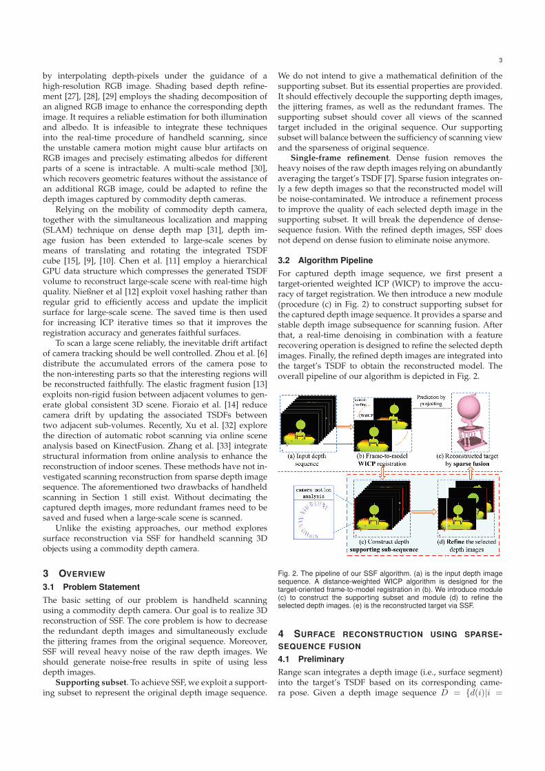
3.2 Algorithm PipelineFor captured depth image sequence, we first present atarget-oriented weighted ICP (WICP) to improve the accu-racy of target registration. We then introduce a new module(procedure (c) in Fig. 2) to construct supporting subset forthe captured depth image sequence. It provides a sparse andstable depth image subsequence for scanning fusion. Afterthat, a real-time denoising in combination with a featurerecovering operation is designed to refine the selected depthimages. Finally, the refined depth images are integrated intothe target’s TSDF to obtain the reconstructed model. Theoverall pipeline of our algorithm is depicted in Fig. 2.
Fig. 2. The pipeline of our SSF algorithm. (a) is the input depth imagesequence. A distance-weighted WICP algorithm is designed for thetarget-oriented frame-to-model registration in (b). We introduce module(c) to construct the supporting subset and module (d) to refine theselected depth images. (e) is the reconstructed target via SSF.
4 SURFACE RECONSTRUCTION USING SPARSE-SEQUENCE FUSION
4.1 PreliminaryRange scan integrates a depth image (i.e., surface segment)into the target’s TSDF based on its corresponding came-ra pose. Given a depth image sequence D = {d(i)|i =
4
1, · · · , N} with N consecutive views, we attempt to con-struct a supporting subset S = {s(j)|j = 1, · · · ,M} (S ⊂ Dand M < N ), which could sufficiently represent the initialsequence D and cut down the redundant depth images aswell as the jittering frames. We denote the camera trajectoryas a set of sensor poses CP, i.e.,
CP = {cp1, cp2, · · · , cpi, · · · , cpN}. (1)
Each pose cp consists of a view orientation v and a cameralocation l. For example, the camera’s pose of the i-th framecpi can be expressed as
cpi = (vi, li). (2)
The motion between two consecutive poses is representedby a rigid transformation matrix T, defined as,
T =
[R3×3 t3×1
01×3 1
], (3)
namely,
cpi = T · cpi−1. (4)
The rotation transformation R and the translation t arecalculated by a coarse-to-fine ICP procedure between thei-th depth image and the projected depth image [7].
4.2 Construction of the supporting subsetOur method reduces redundant data through sparsely sam-pling the original depth image sequence. Since the regis-tration of depth image is based on the views’ overlaps [7],we should hold proper redundancy to make the registrationsmooth rather than eliminating all the overlaps. Therefore,we construct a supporting subset to reconstruct an objectwith minority but sufficient depth images.
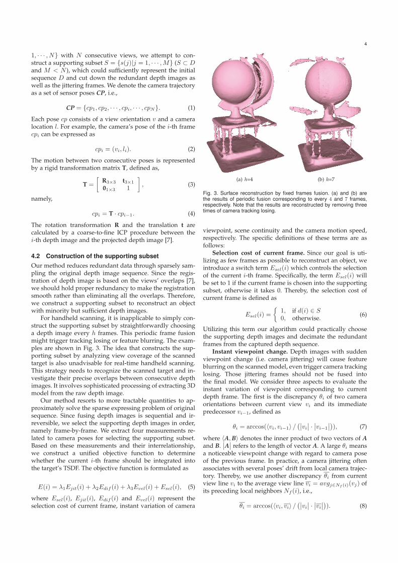
For handheld scanning, it is inapplicable to simply con-struct the supporting subset by straightforwardly choosinga depth image every h frames. This periodic frame fusionmight trigger tracking losing or feature blurring. The exam-ples are shown in Fig. 3. The idea that constructs the sup-porting subset by analyzing view coverage of the scannedtarget is also unadvisable for real-time handheld scanning.This strategy needs to recognize the scanned target and in-vestigate their precise overlaps between consecutive depthimages. It involves sophisticated processing of extracting 3Dmodel from the raw depth image.
Our method resorts to more tractable quantities to ap-proximately solve the sparse expressing problem of originalsequence. Since fusing depth images is sequential and ir-reversible, we select the supporting depth images in order,namely frame-by-frame. We extract four measurements re-lated to camera poses for selecting the supporting subset.Based on these measurements and their interrelationship,we construct a unified objective function to determinewhether the current i-th frame should be integrated intothe target’s TSDF. The objective function is formulated as
E(i) = λ1Ejit(i) + λ2Edif (i) + λ3Evel(i) + Esel(i), (5)
where Esel(i), Ejit(i), Edif (i) and Evel(i) represent theselection cost of current frame, instant variation of camera
(a) h=4 (b) h=7
Fig. 3. Surface reconstruction by fixed frames fusion. (a) and (b) arethe results of periodic fusion corresponding to every 4 and 7 frames,respectively. Note that the results are reconstructed by removing threetimes of camera tracking losing.
viewpoint, scene continuity and the camera motion speed,respectively. The specific definitions of these terms are asfollows:
Selection cost of current frame. Since our goal is uti-lizing as few frames as possible to reconstruct an object, weintroduce a switch term Esel(i) which controls the selectionof the current i-th frame. Specifically, the term Esel(i) willbe set to 1 if the current frame is chosen into the supportingsubset, otherwise it takes 0. Thereby, the selection cost ofcurrent frame is defined as
Esel(i) =
{1, if d(i) ∈ S0, otherwise. (6)
Utilizing this term our algorithm could practically choosethe supporting depth images and decimate the redundantframes from the captured depth sequence.
Instant viewpoint change. Depth images with suddenviewpoint change (i.e. camera jittering) will cause featureblurring on the scanned model, even trigger camera trackinglosing. Those jittering frames should not be fused intothe final model. We consider three aspects to evaluate theinstant variation of viewpoint corresponding to currentdepth frame. The first is the discrepancy θi of two cameraorientations between current view vi and its immediatepredecessor vi−1, defined as
θi = arccos(〈vi, vi−1〉 /(∣∣vi∣∣ · ∣∣vi−1
∣∣)), (7)
where 〈A,B〉 denotes the inner product of two vectors of Aand B.
∣∣A∣∣ refers to the length of vector A. A large θi meansa noticeable viewpoint change with regard to camera poseof the previous frame. In practice, a camera jittering oftenassociates with several poses’ drift from local camera trajec-tory. Thereby, we use another discrepancy θi from currentview line vi to the average view line vi = avgj∈Nf (i)(vj) ofits preceding local neighbors Nf (i), i.e.,
θi = arccos(〈vi, vi〉 /(∣∣vi∣∣ · ∣∣vi∣∣)). (8)
5
We assign 10 preceding frames for Nf (i) in our experiments.In addition, we measure the third discrepancy θi betweencurrent view vi and the k-th view vk (the k-th depth imageis the latest selected frame in supporting subset S before thecurrent frame),
θi = arccos(〈vi, vk〉 /(∣∣vi∣∣ · ∣∣vk∣∣)). (9)
These three indicators are combined together to measurethe instant viewpoint change (namely, the jittering property)of the current i-th frame,
Ejit(i) =
{exp(θi+θi+ ˜θi) − 1, if Esel(i) == 10, if Esel(i) == 0.
(10)
In Eq. (10), the jittering evaluation will be defined only ifthe current frame is selected into the supporting subset (i.e.,Esel(i) takes 1). Otherwise, objective function Eq. (5) takesno account of the jittering evaluation. Fig. 3 illustrates thereconstructed results affected by jittering frames.
Scene continuity. During the down-sampling processof original sequence, sufficient scene overlap between twoselected supporting frames should be maintained. Our algo-rithm takes the accumulated variation of camera pose as theevaluation of scene continuity. The accumulated differenceEdif (i) from the latest selected k-th depth image to currenti-th frame is defined as
Edif (i) =
{ ∑ij=k+1 (cpj � cpj−1) , if Esel(i) == 0
0, if Esel(i) == 1,(11)
where the notation � denotes the difference of two consec-utive camera poses. It regards both the camera’s orientationand location, namely,
cpj � cpj−1 = s · θj + tj . (12)
Orientation change θj refers to Eq. (7). Location offset tjis formulated as
tj = ‖lj−1 − lj‖2. (13)
s is the tradeoff between camera’s orientation and its loca-tion. We set s as 25 (one degree orientation change corre-sponds to 26.18mm target translation when we set the came-ra 1.5m away from the scanned object) in our experiments.
The term Edif (i) records a local accumulation of came-ra pose change if the current frame is abandoned (i.e.,Esel(i) == 0). Once the current i-th frame is selectedinto the supporting subset, this record will be reset andEdif (i) will be assigned to zero again. In Eq. (11), a smallEdif (i) means higher scene continuity while a large valuecorresponds to lower scene continuity.
Camera motion speed. For the handheld scanning man-ner, camera motion speed might vary from time to time.When the camera moves with a high speed, the captureddepth sequence will contain less frames. We introduce aterm Evel(i) to evaluate the camera motion velocity
Evel(i) =
{ �tim
− T
M, if �ti
m− T
M> 0, Esel(i) == 0
0, otherwise,(14)
where �ti =∑i
j=i−m tj is the accumulated distance ofcamera motion from the (i − m)-th frame to the i-th frame,�ti/m denotes the average distance that the camera hastraversed in m frames. This speed term will be calculatedonly if current camera speed exceeds an average speedthreshold T/M (T and M are the total distance of cameramotion and the corresponding frame number respectively)and the current i-th frame is not selected into the supportingsubset S.
In essence, the opposite relation implied in Eq. (5) isthat both scene continuity and camera speed compete withsequence sparsity. According to the definitions of Eqs. (11)and (14), Edif (i) and Evel(i) will be accumulated if thecurrent i-th frame is rejected, otherwise they will be resetto zero. Moreover, the term Ejit(i) of viewpoint changeaccounts for the jittering evaluation of current camera pose.Therefore, the selection of current frame is intrinsicallyassociated with local dynamical pose evaluation (i.e., thescene continuity, the camera motion speed, as well as theinstant viewpoint change).
If the current i-th frame is selected our method will refineits surface segment. Then the refined surface will be fusedby integrating it to the target’s TSDF. Otherwise the currenti-th frame will be excluded. Our algorithm successivelyiterates this process for all the captured depth images.It will gradually produce a supporting subset meanwhileprogressively reconstruct the target via SSF.
4.3 Refinement of a selected depth image
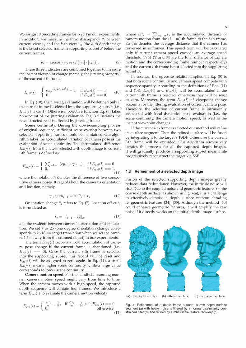
Fusion of the selected supporting depth images greatlyreduces data redundancy. However, the intrinsic noise willrise. Due to the coupled noise and geometric features on thecoarse depth surface, as shown in Fig. 4(a), it is a challengeto effectively denoise a depth surface without abradingits geometric features [34], [35]. Although the method [30]could enhance geometric features, it will amplify the rawnoise if it directly works on the initial depth image surface.
(a) raw depth surface (b) filtered surface (c) recovered surface
Fig. 4. Refinement of a depth frame surface. A raw depth surfacesegment (a) with heavy noise is filtered by a normal dissimilarity con-strained filter (b) and refined by a multi-scale feature recovery (c).
6
We introduce a module for refining each supportingdepth image. It effectively combines a feature-preservingdenoising and a multi-scale feature-recovering operations.
Given a selected depth image d(s), we first perform adenoising like two-step filtering [34], which works on bothnormal and position of each point. The normal ni of a pointpi is updated by a bilateral normal filter n
′i = f1(ni) with
the normal dissimilarity constraint [36], [37]. The positionfilter, p
′i = f2(pi), updates each point along its normal.
We take 8 iterations for the normal filtering and 2 timesposition filtering for each selected depth image surface. Itcould effectively denoise a surface segment while preservesits geometric features as much as possible. Fig. 4(b) showsthe denoised result of a depth image surface.
The initial noise is removed on the filtered depth sur-face. Nevertheless, some notable geometric features are alsoabraded. We did not aim to recover the smoothed detailfeatures which have the same scale level with the noise.Our purpose is to recover those abraded significant geo-metric features and finally to generate a quality 3D model.Therefore, we adapt a multi-scale feature enhancement tech-nique [30] for a denoised depth surface. Unlike the detailextraction method in [30], we use the normal dissimilarityconstrained bilateral filter to separate each detail layer andthe base surface. Specifically, we perform 3 times of filteringand obtain three detail layers, namely,
pr+1i = f2(p
ri ), r = 0, 1, 2, (15)
lodr+1i = 〈(pri − pr+1
i ), nr+1i 〉, (16)
where p0i denotes point pi on the initial surface, p3i is thecorresponding point on base surface, lodr+1
i is the (r+1)-thlevel of detail for point pi, nr+1
i is the normal of point pr+1i
(pi after r times filtering). Starting from the base surface werecover the geometric features following:
ρri = ρr+1i + 2.0 · lodr+1
i · nr+1i , r = 2, 1, 0. (17)
Here, ρ3i is the corresponding point of pi on the base surface(i.e., ρ3i = p3i ), point ρ0i is the updated point of pi on therecovered surface.
Single-frame refinement stated above is performed onthe surface segment while the scanning fusion takes depthimages as input. Therefore, to obtain the refined depthimage, we transfer the refinement of a surface segment tothe update of the corresponding depth image. Specifically,the involved geometric offset of point pi along its normalduring the refinement process will be transferred to thedepth variation of corresponding pixel zi
z′i = |ρ0i − p0i |−→z + zi, (18)
where |A|−→z denotes the projection of vector A along thedepth direction −→z (i.e., camera orientation vs). The updateddepth image d′(s) will participate in the sparse fusionprocess.
The normal dissimilarity constraint used in the filtersand the detail extracting process gradually consolidatessharp features, while the multi-scale enhancement recoversthe abraded notable features. A recovered depth image
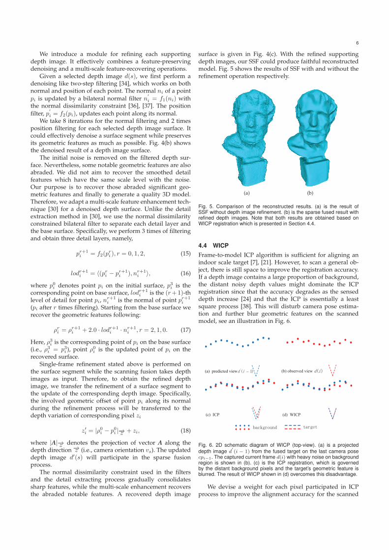
surface is given in Fig. 4(c). With the refined supportingdepth images, our SSF could produce faithful reconstructedmodel. Fig. 5 shows the results of SSF with and without therefinement operation respectively.
(a) (b)
Fig. 5. Comparison of the reconstructed results. (a) is the result ofSSF without depth image refinement. (b) is the sparse fused result withrefined depth images. Note that both results are obtained based onWICP registration which is presented in Section 4.4.
4.4 WICPFrame-to-model ICP algorithm is sufficient for aligning anindoor scale target [7], [21]. However, to scan a general ob-ject, there is still space to improve the registration accuracy.If a depth image contains a large proportion of background,the distant noisy depth values might dominate the ICPregistration since that the accuracy degrades as the senseddepth increase [24] and that the ICP is essentially a leastsquare process [38]. This will disturb camera pose estima-tion and further blur geometric features on the scannedmodel, see an illustration in Fig. 6.
(a) predicted view (b) observed view
(c) ICP (d) WICP
�
Fig. 6. 2D schematic diagram of WICP (top-view). (a) is a projecteddepth image d
′(i − 1) from the fused target on the last camera pose
cpi−1. The captured current frame d(i) with heavy noise on backgroundregion is shown in (b). (c) is the ICP registration, which is governedby the distant background pixels and the target’s geometric feature isblurred. The result of WICP shown in (d) overcomes this disadvantage.
We devise a weight for each pixel participated in ICPprocess to improve the alignment accuracy for the scanned
7
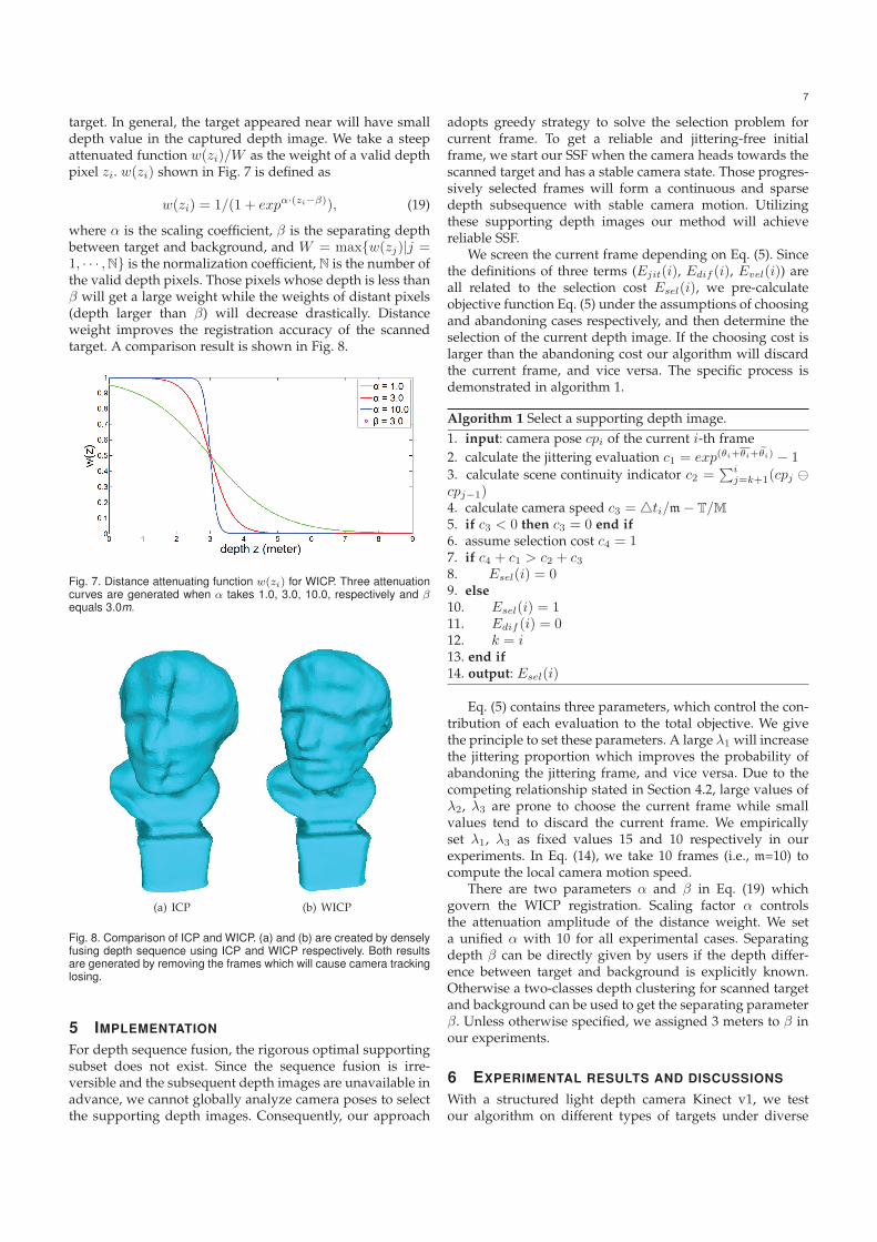
target. In general, the target appeared near will have smalldepth value in the captured depth image. We take a steepattenuated function w(zi)/W as the weight of a valid depthpixel zi. w(zi) shown in Fig. 7 is defined as
w(zi) = 1/(1 + expα·(zi−β)), (19)
where α is the scaling coefficient, β is the separating depthbetween target and background, and W = max{w(zj)|j =1, · · · ,N} is the normalization coefficient, N is the number ofthe valid depth pixels. Those pixels whose depth is less thanβ will get a large weight while the weights of distant pixels(depth larger than β) will decrease drastically. Distanceweight improves the registration accuracy of the scannedtarget. A comparison result is shown in Fig. 8.
Fig. 7. Distance attenuating function w(zi) for WICP. Three attenuationcurves are generated when α takes 1.0, 3.0, 10.0, respectively and βequals 3.0m.
(a) ICP (b) WICP
Fig. 8. Comparison of ICP and WICP. (a) and (b) are created by denselyfusing depth sequence using ICP and WICP respectively. Both resultsare generated by removing the frames which will cause camera trackinglosing.
5 IMPLEMENTATION
For depth sequence fusion, the rigorous optimal supportingsubset does not exist. Since the sequence fusion is irre-versible and the subsequent depth images are unavailable inadvance, we cannot globally analyze camera poses to selectthe supporting depth images. Consequently, our approach
adopts greedy strategy to solve the selection problem forcurrent frame. To get a reliable and jittering-free initialframe, we start our SSF when the camera heads towards thescanned target and has a stable camera state. Those progres-sively selected frames will form a continuous and sparsedepth subsequence with stable camera motion. Utilizingthese supporting depth images our method will achievereliable SSF.
We screen the current frame depending on Eq. (5). Sincethe definitions of three terms (Ejit(i), Edif (i), Evel(i)) areall related to the selection cost Esel(i), we pre-calculateobjective function Eq. (5) under the assumptions of choosingand abandoning cases respectively, and then determine theselection of the current depth image. If the choosing cost islarger than the abandoning cost our algorithm will discardthe current frame, and vice versa. The specific process isdemonstrated in algorithm 1.
Algorithm 1 Select a supporting depth image.1. input: camera pose cpi of the current i-th frame2. calculate the jittering evaluation c1 = exp(θi+θi+ ˜θi) − 13. calculate scene continuity indicator c2 =
∑ij=k+1(cpj �
cpj−1)4. calculate camera speed c3 = �ti/m− T/M5. if c3 < 0 then c3 = 0 end if
6. assume selection cost c4 = 17. if c4 + c1 > c2 + c38. Esel(i) = 09. else
10. Esel(i) = 111. Edif (i) = 012. k = i13. end if
14. output: Esel(i)
Eq. (5) contains three parameters, which control the con-tribution of each evaluation to the total objective. We givethe principle to set these parameters. A large λ1 will increasethe jittering proportion which improves the probability ofabandoning the jittering frame, and vice versa. Due to thecompeting relationship stated in Section 4.2, large values ofλ2, λ3 are prone to choose the current frame while smallvalues tend to discard the current frame. We empiricallyset λ1, λ3 as fixed values 15 and 10 respectively in ourexperiments. In Eq. (14), we take 10 frames (i.e., m=10) tocompute the local camera motion speed.
There are two parameters α and β in Eq. (19) whichgovern the WICP registration. Scaling factor α controlsthe attenuation amplitude of the distance weight. We seta unified α with 10 for all experimental cases. Separatingdepth β can be directly given by users if the depth differ-ence between target and background is explicitly known.Otherwise a two-classes depth clustering for scanned targetand background can be used to get the separating parameterβ. Unless otherwise specified, we assigned 3 meters to β inour experiments.
6 EXPERIMENTAL RESULTS AND DISCUSSIONS
With a structured light depth camera Kinect v1, we testour algorithm on different types of targets under diverse
8
circumstances of handheld scanning. It is implemented ona laptop with an Intel I7 CPU and an Nvidia GeForce GTX970M graphics card.
6.1 Test models
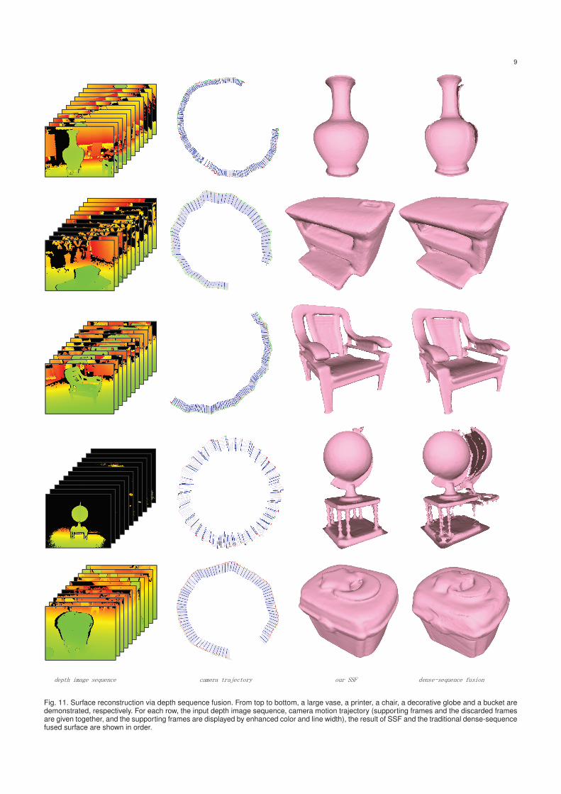
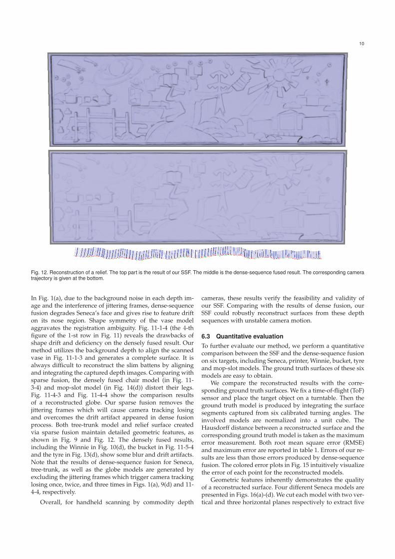
A sculptured Seneca model, as illustrated in Fig. 1, is placedon a table surrounded by a window and two office desks.It is scanned by a limited range of viewpoints. Fig. 9demonstrates an outdoor tree-trunk. To capture the branchof this trunk, we walk around this tree a couple of laps andspirally move down the camera. Fig. 10 is the reconstructionof the Winnie. In the first row of Fig. 11, a vase in a storageroom is scanned. Due to the shape symmetry, aligningdifferent surface segments relying on the scanned target isnotoriously difficult. We resort to the background depth bysetting β as 5 meters to achieve registration of the vase. Thesecond and the third rows in Fig. 11 are a printer and achair respectively. The chair with pluri-genus is complex.It is composed of many basic shape components so thatthe occlusions between different parts will interfere withthe scanning process. The fourth row of Fig. 11 shows thereconstructed result of a decorative globe which is placed ina large hall. We scan it with a fast camera motion speed. Ascanned small bucket is shown in the last row of Fig. 11.Fig. 12 exhibits a large reconstructed relief surface. It isscanned by moving the depth camera along the backgroundwall. Since the relief is embedded on the wall, the separatingdepth β is nonexistent. We set a large value of 5 meters for βto weight each depth pixel in the process of WICP. Figs. 13and 14 correspond to the scans of a toy tyre and a mop-slot,respectively.
All the depth sequences in our experiments are capturedunder handheld scanning manner. For most scanned mod-els, we give the input depth sequence, camera trajectory(camera poses of the supporting depth images are displayedby enhanced color and line width), the result of SSF and thedensely fused result, respectively.
6.2 Qualitative comparison
To show the effectiveness of our method, we conduct mul-tiple comparative experiments. The jittering frames causecamera tracking losing when Seneca, tree-trunk and globemodels are scanned. An example of tracking losing fordensely fusing globe sequence is shown in the accompany-ing video. The process of our SSF which removes the cameratracking losing is also provided.
Fig. 5 demonstrates the results of SSF by using and with-out using refinement operation, respectively. Refinement ofthe selected supporting depth images plays an importantrole in denoising the scanned model and recovering thegeometric features for our SSF.
Comparison results of shape registration using ICP andWICP on Seneca model are given in Fig. 8. Target-orientedWICP decreases the interference of the noisy backgroundpixels and improves the registration accuracy of the scannedtarget. However, the fused jittering frames still blur geomet-ric features on the nose and hair regions in Fig. 8(b).
For each tested model, the results produced by both sp-arse and dense-sequence fusions are exhibited respectively.
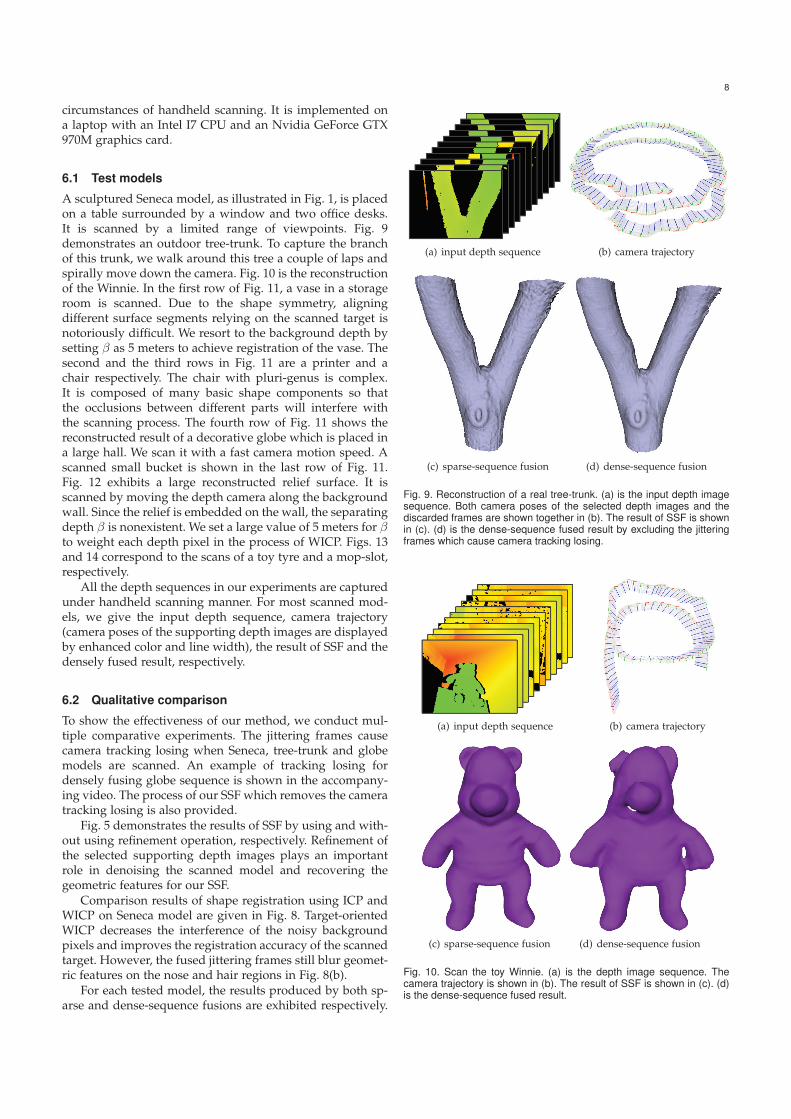
(a) input depth sequence (b) camera trajectory
(c) sparse-sequence fusion (d) dense-sequence fusion
Fig. 9. Reconstruction of a real tree-trunk. (a) is the input depth imagesequence. Both camera poses of the selected depth images and thediscarded frames are shown together in (b). The result of SSF is shownin (c). (d) is the dense-sequence fused result by excluding the jitteringframes which cause camera tracking losing.
(a) input depth sequence (b) camera trajectory
(c) sparse-sequence fusion (d) dense-sequence fusion
Fig. 10. Scan the toy Winnie. (a) is the depth image sequence. Thecamera trajectory is shown in (b). The result of SSF is shown in (c). (d)is the dense-sequence fused result.
9
Fig. 11. Surface reconstruction via depth sequence fusion. From top to bottom, a large vase, a printer, a chair, a decorative globe and a bucket aredemonstrated, respectively. For each row, the input depth image sequence, camera motion trajectory (supporting frames and the discarded framesare given together, and the supporting frames are displayed by enhanced color and line width), the result of SSF and the traditional dense-sequencefused surface are shown in order.
10
Fig. 12. Reconstruction of a relief. The top part is the result of our SSF. The middle is the dense-sequence fused result. The corresponding cameratrajectory is given at the bottom.
In Fig. 1(a), due to the background noise in each depth im-age and the interference of jittering frames, dense-sequencefusion degrades Seneca’s face and gives rise to feature drifton its nose region. Shape symmetry of the vase modelaggravates the registration ambiguity. Fig. 11-1-4 (the 4-thfigure of the 1-st row in Fig. 11) reveals the drawbacks ofshape drift and deficiency on the densely fused result. Ourmethod utilizes the background depth to align the scannedvase in Fig. 11-1-3 and generates a complete surface. It isalways difficult to reconstruct the slim battens by aligningand integrating the captured depth images. Comparing withsparse fusion, the densely fused chair model (in Fig. 11-3-4) and mop-slot model (in Fig. 14(d)) distort their legs.Fig. 11-4-3 and Fig. 11-4-4 show the comparison resultsof a reconstructed globe. Our sparse fusion removes thejittering frames which will cause camera tracking losingand overcomes the drift artifact appeared in dense fusionprocess. Both tree-trunk model and relief surface createdvia sparse fusion maintain detailed geometric features, asshown in Fig. 9 and Fig. 12. The densely fused results,including the Winnie in Fig. 10(d), the bucket in Fig. 11-5-4and the tyre in Fig. 13(d), show some blur and drift artifacts.Note that the results of dense-sequence fusion for Seneca,tree-trunk, as well as the globe models are generated byexcluding the jittering frames which trigger camera trackinglosing once, twice, and three times in Figs. 1(a), 9(d) and 11-4-4, respectively.
Overall, for handheld scanning by commodity depth
cameras, these results verify the feasibility and validity ofour SSF. Comparing with the results of dense fusion, ourSSF could robustly reconstruct surfaces from these depthsequences with unstable camera motion.
6.3 Quantitative evaluationTo further evaluate our method, we perform a quantitativecomparison between the SSF and the dense-sequence fusionon six targets, including Seneca, printer, Winnie, bucket, tyreand mop-slot models. The ground truth surfaces of these sixmodels are easy to obtain.
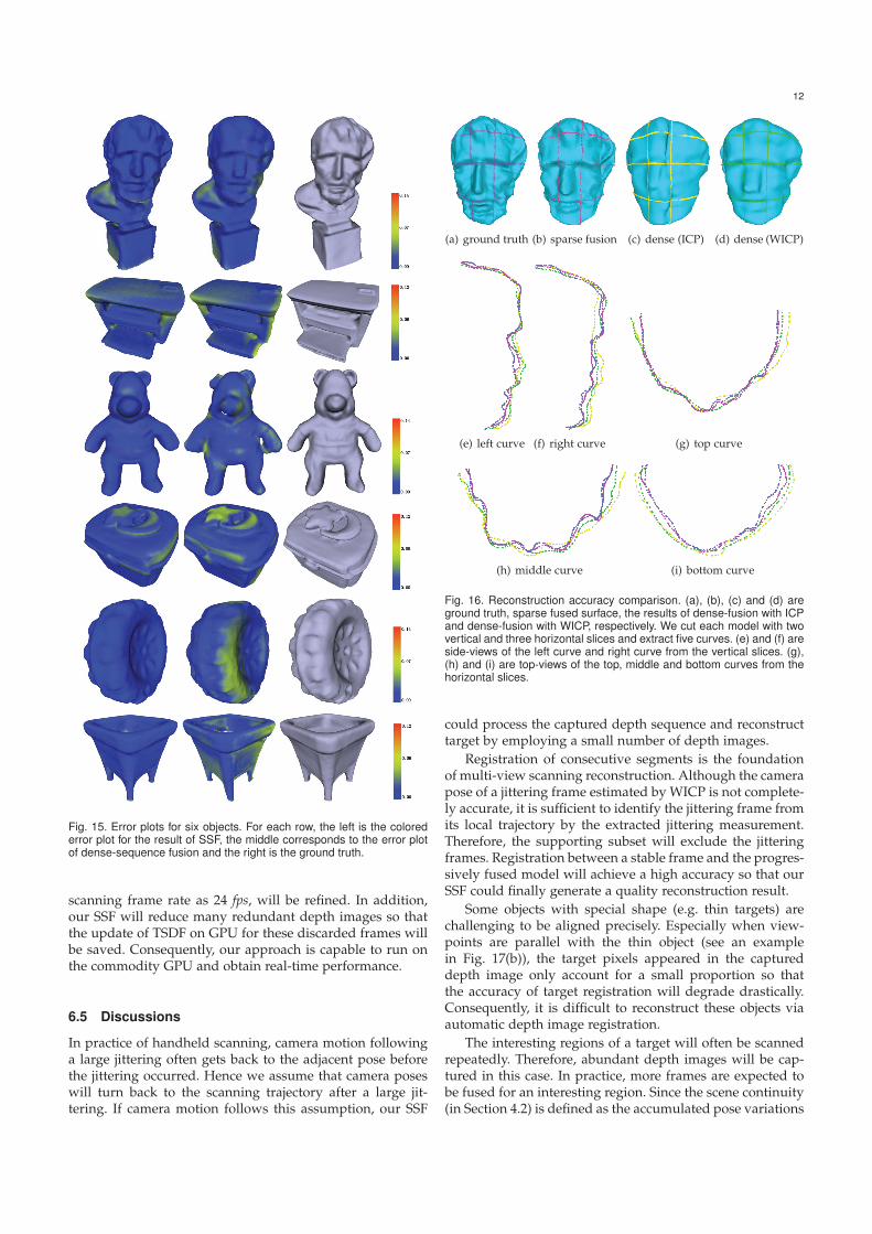
We compare the reconstructed results with the corre-sponding ground truth surfaces. We fix a time-of-flight (ToF)sensor and place the target object on a turntable. Then theground truth model is produced by integrating the surfacesegments captured from six calibrated turning angles. Theinvolved models are normalized into a unit cube. TheHausdorff distance between a reconstructed surface and thecorresponding ground truth model is taken as the maximumerror measurement. Both root mean square error (RMSE)and maximum error are reported in table 1. Errors of our re-sults are less than those errors produced by dense-sequencefusion. The colored error plots in Fig. 15 intuitively visualizethe error of each point for the reconstructed models.
Geometric features inherently demonstrates the qualityof a reconstructed surface. Four different Seneca models arepresented in Figs. 16(a)-(d). We cut each model with two ver-tical and three horizontal planes respectively to extract five
11
(a) input depth sequence (b) camera trajectory
(c) sparse-sequence fusion (d) dense-sequence fusion
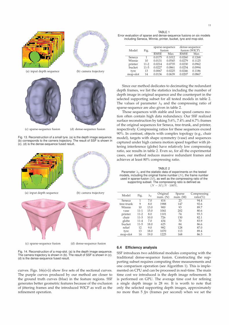
Fig. 13. Reconstruction of a small tyre. (a) is the depth image sequence.(b) corresponds to the camera trajectory. The result of SSF is shown in(c). (d) is the dense-sequence fused result.
(a) input depth sequence (b) camera trajectory
(c) sparse-sequence fusion (d) dense-sequence fusion
Fig. 14. Reconstruction of a mop-slot. (a) is the depth image sequence.The camera trajectory is shown in (b). The result of SSF is shown in (c).(d) is the dense-sequence fused result.
curves. Figs. 16(e)-(i) show five sets of the sectional curves.The purple curves produced by our method are closer tothe ground truth curves (blue) in the feature regions. SSFgenerates better geometric features because of the exclusionof jittering frames and the introduced WICP as well as therefinement operation.
TABLE 1Error evaluation of sparse and dense-sequence fusions on six models
including Seneca, Winnie, printer, bucket, tyre and mop-slot.
Model Fig.sparse-sequence
fusiondense-sequencefusion (WICP)
RMSE Max RMSE MaxSeneca 1 0.0175 0.1012 0.0260 0.1268Winnie 10 0.0131 0.0545 0.0279 0.1125printer 11-2 0.0214 0.0735 0.0230 0.0962bucket 11-5 0.0227 0.0861 0.0254 0.0994
tyre 13 0.0067 0.0225 0.0246 0.1186mop-slot 14 0.0136 0.0639 0.0207 0.0867
Since our method dedicates to decimating the redundantdepth frames, we list the statistics including the number ofdepth image in original sequence and the counterpart in theselected supporting subset for all tested models in table 2.The values of parameter λ2 and the compressing ratio ofsparse-sequence are also given in table 2.
Those sequences with stable and low speed camera mo-tion often contain high data redundancy. Our SSF realizedsurface reconstruction by taking 5.6%, 7.4% and 6.7% framesof the original sequences for Seneca, tree-trunk, and printer,respectively. Compressing ratios for these sequences exceed90%. In contrast, objects with complex topology (e.g., chairmodel), targets with shape symmetry (vase) and sequencescaptured under high camera motion speed together with jit-tering interference (globe) have relatively low compressingratio, see results in table 2. Even so, for all the experimentalcases, our method reduces massive redundant frames andachieves at least 80% compressing ratio.
TABLE 2Parameter λ2 and the statistic data of experiments on the tested
models, including the original frame number (N ), the frame numberused in sparse-fusion (M ), as well as the compressing ratio of the
supporting subset. The compressing ratio is defined as(N −M)/N · 100%.
Model Fig. λ2Originalnum. (N)
Sparsenum. (M)
Compressingratio(%)
Seneca 1 7.0 414 23 94.4tree-trunk 9 8.0 1988 147 92.6
Winnie 10 13.0 900 93 89.7vase 11-1 15.0 1041 202 80.6
printer 11-2 8.0 1101 74 93.3chair 11-3 10.0 726 130 82.1globe 11-4 7.0 434 70 83.9
bucket 11-5 18.0 625 84 86.6relief 12 9.0 982 128 87.0tyre 13 18.0 1070 113 89.4
mop-slot 14 19.0 1225 168 86.3
6.4 Efficiency analysisSSF introduces two additional modules comparing with thetraditional dense-sequence fusion. Constructing the sup-porting subset requires computing three measurements andone comparison operation (see Algorithm 1). This is imple-mented on CPU and can be processed in real-time. The maintime cost we introduced is the depth image refinement. Itis performed on GPU. The average time cost for refininga single depth image is 28 ms. It is worth to note thatonly the selected supporting depth images, approximatelyno more than 5 fps (frames per second) when we set the
12
Fig. 15. Error plots for six objects. For each row, the left is the colorederror plot for the result of SSF, the middle corresponds to the error plotof dense-sequence fusion and the right is the ground truth.
scanning frame rate as 24 fps, will be refined. In addition,our SSF will reduce many redundant depth images so thatthe update of TSDF on GPU for these discarded frames willbe saved. Consequently, our approach is capable to run onthe commodity GPU and obtain real-time performance.
6.5 Discussions
In practice of handheld scanning, camera motion followinga large jittering often gets back to the adjacent pose beforethe jittering occurred. Hence we assume that camera poseswill turn back to the scanning trajectory after a large jit-tering. If camera motion follows this assumption, our SSF
(a) ground truth (b) sparse fusion (c) dense (ICP) (d) dense (WICP)
(e) left curve (f) right curve (g) top curve
(h) middle curve (i) bottom curve
Fig. 16. Reconstruction accuracy comparison. (a), (b), (c) and (d) areground truth, sparse fused surface, the results of dense-fusion with ICPand dense-fusion with WICP, respectively. We cut each model with twovertical and three horizontal slices and extract five curves. (e) and (f) areside-views of the left curve and right curve from the vertical slices. (g),(h) and (i) are top-views of the top, middle and bottom curves from thehorizontal slices.
could process the captured depth sequence and reconstructtarget by employing a small number of depth images.
Registration of consecutive segments is the foundationof multi-view scanning reconstruction. Although the camerapose of a jittering frame estimated by WICP is not complete-ly accurate, it is sufficient to identify the jittering frame fromits local trajectory by the extracted jittering measurement.Therefore, the supporting subset will exclude the jitteringframes. Registration between a stable frame and the progres-sively fused model will achieve a high accuracy so that ourSSF could finally generate a quality reconstruction result.
Some objects with special shape (e.g. thin targets) arechallenging to be aligned precisely. Especially when view-points are parallel with the thin object (see an examplein Fig. 17(b)), the target pixels appeared in the captureddepth image only account for a small proportion so thatthe accuracy of target registration will degrade drastically.Consequently, it is difficult to reconstruct these objects viaautomatic depth image registration.
The interesting regions of a target will often be scannedrepeatedly. Therefore, abundant depth images will be cap-tured in this case. In practice, more frames are expected tobe fused for an interesting region. Since the scene continuity(in Section 4.2) is defined as the accumulated pose variations

13
between adjacent frames rather than the direct differencefrom last selected depth image to current frame, our methodwill select more supporting frames for a repeatedly scannedinteresting region.
6.6 LimitationsThere are mainly three limitations of our method: (1) Thesupporting subset is not necessarily an optimal sparse repre-sentation of the original depth sequence. We did not providea rigorous theoretical analysis based on viewpoints coverageof the scanned target. Nevertheless, the supporting sub-set satisfies our problem setting and provides an effectivebalance between the sparsity of the original sequence andthe continuity of the camera viewpoint. (2) For handheldscanning, the camera pose should get back to the continuoustrajectory once a large jittering occurs. Our approach stillsuffers from the scanning reset for a drastic off-track cameramotion without pose recovery. (3) Handheld scanning of thethin targets is still challenging at present. Fig. 17 shows afailure case when a bike is scanned. Although sparse fusiongenerates better result than dense fusion, the reconstructedsurface is incomplete and has severe drift artifacts.
(a) (b)
(c)
Fig. 17. Scan a bike. (a) and (b) are the side-view and front-view of oursparse-sequence fused result, respectively. (c) is the result of dense-sequence fusion.
7 CONCLUSION
Handheld scanning using commodity depth cameras hasbrought us a flexible way to get 3D models. However,directly fusing all the captured depth images cannot obtainsatisfactory results. In the context of handheld scanningwith commodity depth cameras, our work explores thedirection of surface reconstruction by using a small num-ber of the captured depth images for the first time. We
presented a sparse-sequence fusion method in this paper.It constructs a supporting subset for the captured depthimage sequence meanwhile fuses these supporting depthimages sequentially. Each raw depth image selected intothe supporting subset is refined by a combined operationwhich contains a feature-preserving surface denoising anda multi-scale geometric feature recovery. This refinementoperation breaks the dependence of dense-sequence fusion.Experimental results show that our method could effectivelydecrease the redundant depth images and reject the interfer-ence of the jittering frames for low-cost handheld scanning.
For future work, we would like to investigate how toconstruct the supporting subset for original depth sequencerelying on 3D content of the scanned target. Employing 3Dcontent will enable the screening of the supporting framesmore accurate. Another problem that we intend to exploreis to scan and reconstruct those thin objects to enhance ourSSF method.
ACKNOWLEDGMENTS
We thank all the anonymous reviewers for their insightfulcomments and constructive suggestions. This work waspartly supported by the NSFC (No. 61472288, 61672390),NCET (NCET-13-0441), the Fundamental Research Fundsfor the Central Universities (2042015kf0181, 2452015059),and the State Key Lab of Software Engineering (SKLSE-2015-A-05). Chunxia Xiao is the corresponding author.
REFERENCES
[1] Microsoft, “Kinect camera,” http://www.xbox.com/en-US/kinect/default.htm, 2010.
[2] D. Lanman and G. Taubin, “Build your own 3d scanner: 3dphotography for beginners,” in ACM SIGGRAPH 2009 Courses.ACM, 2009, p. 8.
[3] B. Curless, “From range scans to 3d models,” ACM SIGGRAPHComputer Graphics, vol. 33, no. 4, pp. 38–41, 1999.
[4] J. Tong, J. Zhou, L. Liu, Z. Pan, and H. Yan, “Scanning 3d fullhuman bodies using kinects,” IEEE transactions on visualization andcomputer graphics, vol. 18, no. 4, pp. 643–650, 2012.
[5] R. A. Newcombe, D. Fox, and S. M. Seitz, “Dynamicfusion: Re-construction and tracking of non-rigid scenes in real-time,” inProceedings of the IEEE conference on computer vision and patternrecognition, 2015, pp. 343–352.
[6] Q.-Y. Zhou and V. Koltun, “Dense scene reconstruction with pointsof interest,” ACM Transactions on Graphics (TOG), vol. 32, no. 4, p.112, 2013.
[7] R. A. Newcombe, S. Izadi, O. Hilliges, D. Molyneaux, D. Kim,A. J. Davison, P. Kohi, J. Shotton, S. Hodges, and A. Fitzgibbon,“Kinectfusion: Real-time dense surface mapping and tracking,” inMixed and augmented reality (ISMAR), 2011 10th IEEE internationalsymposium on. IEEE, 2011, pp. 127–136.
[8] S. Izadi, D. Kim, O. Hilliges, D. Molyneaux, R. Newcombe,P. Kohli, J. Shotton, S. Hodges, D. Freeman, A. Davison et al.,“Kinectfusion: real-time 3d reconstruction and interaction usinga moving depth camera,” in Proceedings of the 24th annual ACMsymposium on User interface software and technology. ACM, 2011,pp. 559–568.
[9] H. Roth and M. Vona, “Moving volume kinectfusion.” in BMVC,2012, pp. 1–11.
[10] T. Whelan, M. Kaess, M. Fallon, H. Johannsson, J. Leonard, andJ. McDonald, “Kintinuous: Spatially extended kinectfusion,” 2012.
[11] J. Chen, D. Bautembach, and S. Izadi, “Scalable real-time volumet-ric surface reconstruction,” ACM Trans. Graph., vol. 32, no. 4, pp.113:1–113:16, Jul. 2013.
[12] M. Nießner, M. Zollhofer, S. Izadi, and M. Stamminger, “Real-time3d reconstruction at scale using voxel hashing,” ACM Transactionson Graphics (TOG), vol. 32, no. 6, p. 169, 2013.
14
[13] Q.-Y. Zhou, S. Miller, and V. Koltun, “Elastic fragments for densescene reconstruction,” in 2013 IEEE International Conference onComputer Vision. IEEE, 2013, pp. 473–480.
[14] N. Fioraio, J. Taylor, A. Fitzgibbon, L. Di Stefano, and S. Izadi,“Large-scale and drift-free surface reconstruction using onlinesubvolume registration,” in 2015 IEEE Conference on ComputerVision and Pattern Recognition (CVPR). IEEE, 2015, pp. 4475–4483.
[15] F. Heredia and R. Favier, “Kinfu large scale in pcl,”http://pointclouds.org/documentation/tutorials/using kinfularge scale.php, 2012.
[16] B. Curless and M. Levoy, “A volumetric method for buildingcomplex models from range images,” in Proceedings of the 23rdannual conference on Computer graphics and interactive techniques.ACM, 1996, pp. 303–312.
[17] J. Yang, H. Li, and Y. Jia, “Go-icp: Solving 3d registration efficientlyand globally optimally,” in Proceedings of the IEEE InternationalConference on Computer Vision, 2013, pp. 1457–1464.
[18] D. Holz, A. E. Ichim, F. Tombari, R. B. Rusu, and S. Behnke,“Registration with the point cloud library: A modular frameworkfor aligning in 3-d,” IEEE Robotics & Automation Magazine, vol. 22,no. 4, pp. 110–124, 2015.
[19] P. BESL and N. MCKAY, “A method for registration of 3-d shapes,”IEEE transactions on pattern analysis and machine intelligence, vol. 14,no. 2, pp. 239–256, 1992.
[20] Y. Chen and G. Medioni, “Object modelling by registration ofmultiple range images,” Image and vision computing, vol. 10, no. 3,pp. 145–155, 1992.
[21] R. A. Newcombe, S. J. Lovegrove, and A. J. Davison, “Dtam: Densetracking and mapping in real-time,” in 2011 international conferenceon computer vision. IEEE, 2011, pp. 2320–2327.
[22] M. Soucy and D. Laurendeau, “Multi-resolution surface model-ing from multiple range views,” in Computer Vision and PatternRecognition, 1992. Proceedings CVPR’92., 1992 IEEE Computer SocietyConference on. IEEE, 1992, pp. 348–353.
[23] G. Turk and M. Levoy, “Zippered polygon meshes from rangeimages,” in Proceedings of the 21st annual conference on Computergraphics and interactive techniques. ACM, 1994, pp. 311–318.
[24] K. Khoshelham, “Accuracy analysis of kinect depth data,” inISPRS workshop laser scanning, vol. 38, no. 5, 2011, p. W12.
[25] L. Vosters, C. Varekamp, and G. de Haan, “Evaluation of efficienthigh quality depth upsampling methods for 3dtv,” in IS&T/SPIEElectronic Imaging. International Society for Optics and Photonics,2013, pp. 865 005–865 005.
[26] J. Yang, X. Ye, K. Li, C. Hou, and Y. Wang, “Color-guided depth re-covery from rgb-d data using an adaptive autoregressive model,”IEEE Transactions on Image Processing, vol. 23, no. 8, pp. 3443–3458,2014.
[27] Y. Han, J.-Y. Lee, and I. So Kweon, “High quality shape from asingle rgb-d image under uncalibrated natural illumination,” inProceedings of the IEEE International Conference on Computer Vision,2013, pp. 1617–1624.
[28] C. Wu, M. Zollhofer, M. Nießner, M. Stamminger, S. Izadi, andC. Theobalt, “Real-time shading-based refinement for consumerdepth cameras,” ACM Transactions on Graphics (Proceedings of SIG-GRAPH Asia 2014), vol. 33, p. 3, 2014.
[29] R. Or-El, G. Rosman, A. Wetzler, R. Kimmel, and A. M. Bruck-stein, “Rgbd-fusion: Real-time high precision depth recovery,” inProceedings of the IEEE Conference on Computer Vision and PatternRecognition, 2015, pp. 5407–5416.
[30] L. Yang, C. Xiao, and J. Fang, “Multi-scale geometric detail en-hancement for time-varying surfaces,” Graphical Models, vol. 76,no. 5, pp. 413–425, 2014.
[31] C. Kerl, J. Sturm, and D. Cremers, “Dense visual slam for rgb-dcameras,” in 2013 IEEE/RSJ International Conference on IntelligentRobots and Systems. IEEE, 2013, pp. 2100–2106.
[32] K. Xu, H. Huang, Y. Shi, H. Li, P. Long, J. Caichen, W. Sun,and B. Chen, “Autoscanning for coupled scene reconstruction andproactive object analysis,” ACM Transactions on Graphics (TOG),vol. 34, no. 6, p. 177, 2015.
[33] Y. Zhang, W. Xu, Y. Tong, and K. Zhou, “Online structure analysisfor real-time indoor scene reconstruction,” ACM Transactions onGraphics (TOG), vol. 34, no. 5, p. 159, 2015.
[34] A. Belyaev and Y. Ohtake, “A comparison of mesh smoothingmethods,” in Israel-Korea Bi-national conference on geometric modelingand computer graphics, vol. 2. Citeseer, 2003.
[35] P.-S. Wang, X.-M. Fu, Y. Liu, X. Tong, S.-L. Liu, and B. Guo,“Rolling guidance normal filter for geometric processing,” ACMTransactions on Graphics (TOG), vol. 34, no. 6, p. 173, 2015.
[36] A. C. Oztireli, G. Guennebaud, and M. Gross, “Feature preservingpoint set surfaces based on non-linear kernel regression,” in Com-puter Graphics Forum, vol. 28, no. 2. Wiley Online Library, 2009,pp. 493–501.
[37] L. Yang, Q. Yan, and C. Xiao, “Shape-controllable geometrycompletion for point cloud models,” The Visual Computer, 2016,doi:10.1007/s00371-016-1208-1.
[38] K. S. Arun, T. S. Huang, and S. D. Blostein, “Least-squares fittingof two 3-d point sets,” IEEE Transactions on pattern analysis andmachine intelligence, no. 5, pp. 698–700, 1987.
Long Yang received the BSc degree in infor-mation and computing science from Chang′anUniversity, China, in 2004 and the MSc degreein computer science from Northwest A&F Uni-versity, China, in 2010, respectively. Currently,he is a lecturer at Northwest A&F University andworking toward the PhD degree in the ComputerSchool, Wuhan University. His research interestsinclude computer graphics, digital geometry pro-cessing and 3D computer vision.
Qingan Yan received his BSc degree in comput-er science from Hubei University for Nationali-ties, China, and the MSc degree in computer vi-sion and virtual reality from Southwest Universityof Science and Technology, China, in 2012. He iscurrently working toward the PhD degree in theComputer Science Department of Wuhan Uni-versity. His research interests include computervision, computer graphics and virtual reality.
Yanping Fu received the BSc degree in com-puter science and technology from ChangchunUniversity, in 2008 and the MSc degree in com-puter science and technology from Yanshan Uni-versity, in 2012. Currently, he is working towardthe PhD degree in the Computer School, WuhanUniversity. His research interests include geom-etry processing, 3D reconstruction and SLAM.
Chunxia Xiao received the BSc and MSc de-grees from the Mathematics Department of Hu-nan Normal University in 1999 and 2002, re-spectively, and the PhD degree from the StateKey Lab of CAD & CG of Zhejiang Universi-ty in 2006. Currently, he is a professor at theSchool of Computer, Wuhan University, China.From October 2006 to April 2007, he workedas a postdoc at the Department of ComputerScience and Engineering, Hong Kong Universityof Science and Technology, and during February
2012 to February 2013, he visited University of California-Davis for oneyear. His main interests include computer graphics, computer vision andmachine learning. He is a member of IEEE.