Embed Size (px)
Citation preview
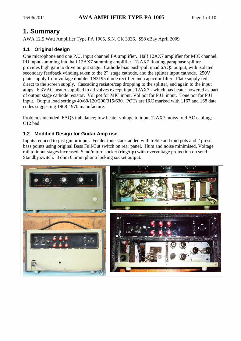
16/06/2011 AWA AMPLIFIER TYPE PA 1005 Page 1 of 10
1. Summary AWA 12.5 Watt Amplifier Type PA 1005, S.N. CK 3336. $58 eBay April 2009
1.1 Original design One microphone and one P.U. input channel PA amplifier. Half 12AX7 amplifier for MIC channel. PU input summing into half 12AX7 summing amplifier. 12AX7 floating paraphase splitter provides high gain to drive output stage. Cathode bias push-pull quad 6AQ5 output, with isolated secondary feedback winding taken to the 2nd stage cathode, and the splitter input cathode. 250V plate supply from voltage doubler 1N3195 diode rectifier and capacitor filter. Plate supply fed direct to the screen supply. Cascading resistor/cap dropping to the splitter, and again to the input amps. 6.3VAC heater supplied to all valves except input 12AX7 - which has heater powered as part of output stage cathode resistor. Vol pot for MIC input. Vol pot for P.U. input. Tone pot for P.U. input. Output load settings 40/60/120/200/315/630. POTs are IRC marked with 1167 and 168 date codes suggesting 1968-1970 manufacture. Problems included: 6AQ5 imbalance; low heater voltage to input 12AX7; noisy; old AC cabling; C12 bad.
1.2 Modified Design for Guitar Amp use Inputs reduced to just guitar input. Fender tone stack added with treble and mid pots and 2 preset bass points using original Bass Full/Cut switch on rear panel. Hum and noise minimised. Voltage rail to input stages increased. Send/return socket (ring/tip) with overvoltage protection on send. Standby switch. 8 ohm 6.5mm phono locking socket output.

16/06/2011 AWA AMPLIFIER TYPE PA 1005 Page 2 of 10
2. Modifications • Replaced AC input cable and internal AC wiring. Moved on/off switch to after fuse. • All wiring with constellation star ground configuration. Shielded pair cable to Pots and rear
Bass switch. • Isolated 6.5mm socket input, switched to ground. Changed R1 from 2M2 to 1M and moved
to input socket. 68K series input added to grid. 33uF cathode bypass to input 12AX7. • Disconnected P.U. input circuit from V1B. 220K R6 deleted to reduce noise, as summer
function removed. • Newer electrolytic for powering. • Attenuator (2:1) to splitter input stage, to allow splitter/output stage to be driven into
acceptable overdrive level. Added 470k grid stopper to V1B and V2A to minimise overdrive distortion.
• Individual 390R screen stoppers, to reduce screen dissipation, and allow individual screen levels to be generated.
• 10R individual 6AQ5 cathode resistors for nominal bias checking (screen + plate). • Common cathode resistance raised to 135R total (30mA each tube average). Tubes run
cool, and mostly in Class A - with Class B only during heavy load peaks. • Added Fender-type tone stack with Mid & Treble pots. Bass cut switched from max to min. • New power switch at rear. Standby switch at front – isolates HT secondary winding. • V1 heater was powered as part of cathode bias – but this didn’t allow standby pre-heat. All
heaters run AC with +40VDC biased humdinger pot. • MOV and 4k7 across each OT primary half winding. • Locking 6.5mm socket for 8 to 15 ohm output. Added 10R 0.1uF zobel network to partially
load output (f~160kHz). Separated OT secondary windings at taps and connected the four middle windings (40-60; 60-120; 120-200; 200-315) in parallel to provide 8R output – the two outer windings (0-40, 315-630) are left open and unconnected. Earthed one side of output.
Possible future mods: • 1Mohm return voltage trimmer – 9mm size pot just above socket. • Green LED to add to bulb to indicate standby/on – powered from 15V cathode bias. • Add 22k build-out resistor in output of second half of PI stage to balance PI. • VVR on VS1 only, with complementary attenuation of PI output signal level

16/06/2011 AWA AMPLIFIER TYPE PA 1005 Page 3 of 10
3. Measurements Voltage rail regulation. Rail Idle (2x 12AX7) Idle (2x 12AY7) VS1 242V 244 VS2 227V 223 VS3 214V 203 VS4 41V 41 V1A plate 148V 106 V1B plate 141V 87 V2A plate 140V 89 V2B plate 135V 87 Heater 1 6.43Vrms Sec HT Ripple V1 0.86Vrms Ripple V2 ~20mVrms Ripple V3 ~10mVrms Valve bias: 27+36mA; 32+26mA. 12VAC 50Hz nominal applied to output transformer 40R winding Winding Voltage rms Turns ratio; Pri Impedance; Spec level; Notes Pri P-P: BLU to Vi 154.9 1 ; Ω; N/A; appears to be 5k P-P Sec: Feedback Winding 15.46 10.0; Ω; N/A Ω; 50Ω, based on 5k P-P Sec: 40 to Com 12.39 12.5; 6,250 Ω; 40 Ω; 32Ω, based on 5k P-P Sec: 60 to Com 18.54 8.35; 4,185Ω; 60Ω; 72Ω, based on 5k P-P Sec: 120 to Com 24.7 6.27; 4,718 Ω; 120Ω; Sec: 200 to Com 30.83 5.02; 5,044 Ω; 200Ω; Sec: 315 to Com 36.8 4.21; 5,582Ω; 315 Ω; Sec: 630 to Com 55.2 2.81; 4,961Ω; 630 Ω; 12VAC 50Hz nominal applied to 40 + 630 windings on output transformer Winding Voltage rms Turns ratio; Impedance; Notes Pri P-P: BLU to Vi 62.0 1 ; assumed to be 5k P-P Sec: 40 to 630 windings 12.2 5.08; 194 Ω; based on 5k P-P Sec: 40 to 60 2.44 25.4; 7.75 Ω; based on 5k P-P Sec: 60 to 120 2.44 25.4; 7.75Ω; based on 5k P-P Sec: 120 to 200 2.44 25.4; 7.75 Ω; based on 5k P-P Sec: 200 to 315 2.44 25.4; 7.75 Ω; based on 5k P-P Output transformer primary DC resistance: 162Ω plate-to-plate. Output transformer secondary DC resistance: 4.2Ω 630 winding. Power transformer primary DC resistance: 46Ω. Power transformer secondary DC resistance: 20Ω. The effective impedance of the winding between the 40R and 60R taps is 8R, as is the impedance between 60R to 120R, and 120R to 200R, and 200R to 315R. These four windings were separated and wired in parallel, to give an 8R output – they comprise 45% of secondary winding turns. Alternatively, the Com-40R, 40R to 120R, and 120R to 315R could be wired in parallel for a 32R output using 67% of secondary winding turns.

16/06/2011 AWA AMPLIFIER TYPE PA 1005 Page 4 of 10
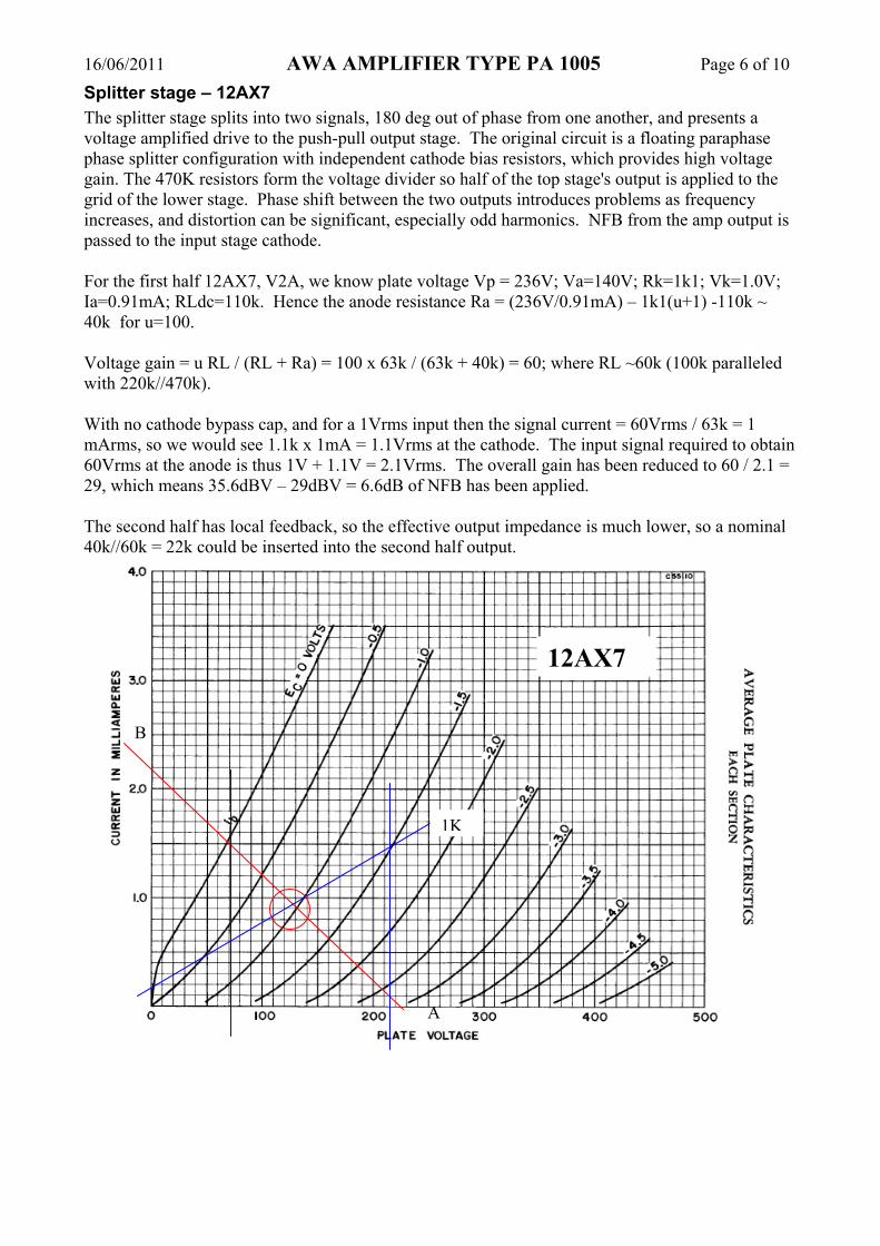
4. Design Info4.1 Input stage – 12AX7Measurements based on Modified circuit.
For the first half 12AX7, V1A, plate voltage Vp = 220V; Va=150V; Rk=1k96; Vk=1.37V;Ia=0.7mA; RLdc=100k.
The input voltage swing limit is from the bias point at Vgk=-1.26V to Vgk=0V, which is about 2.5Vpp or 0.9Vrms. Referring to the loadline, the plate voltage would swing about 140V, from about 70V to 210V, with a mid point of 150V [210-150=60V; 150-70=80V] which indicates a reasonable amount of 2nd harmonic distortion. This gives a nominal gain of 140/2.5 = 56.
For the second half 12AX7, V1B, we know plate voltage Vp = 220V; Va=140V; Rk=2k06;Vk=1.38V; Ia=0.7mA; RLdc=114k.
With no cathode bypass cap, and for a 1Vrms input then the signal current = 64Vrms / 108k = 0.59mArms, so we would see 2.06k x 0.59mA = 1.21Vrms at the cathode. The input signal required to obtain 64Vrms at the anode is thus 1V + 1.21V = 2.21Vrms. The overall gain has been reduced to 64 / 2.21 = 29, which means 36.1dBV – 29.2BV = 6.9dB of NFB has been applied.
The input voltage swing limit is from the bias point at Vgk=-1.38V to Vgk=0V, which is about 2.8Vpp or 1Vrms. Referring to the loadline, the plate voltage would swing about 160V, from about 60V to 220V, with a mid point of 157V [220-140=80V; 140-60=80V]. This gives a nominal gain of 140/2.5 = 56.
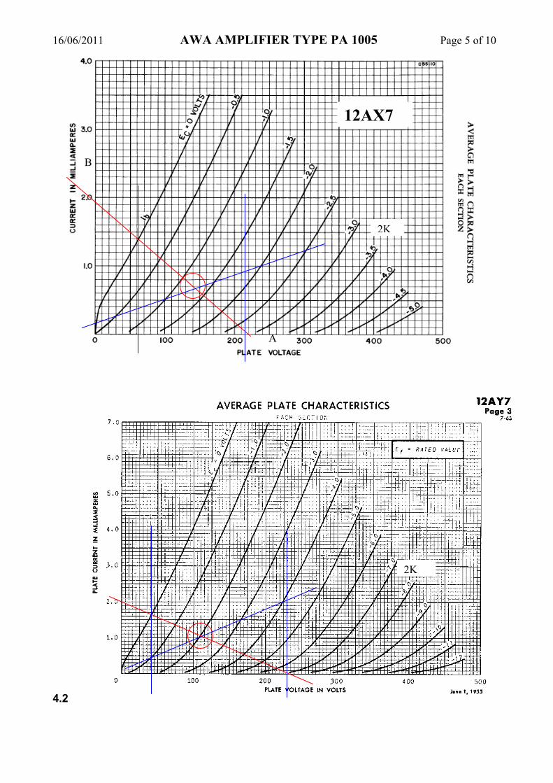
A
B
12AX7
2K
16/06/2011 AWA AMPLIFIER TYPE PA 1005 Page 5 of 10
4.2
A
B
12AX7
2K
2K
16/06/2011 AWA AMPLIFIER TYPE PA 1005 Page 6 of 10Splitter stage – 12AX7The splitter stage splits into two signals, 180 deg out of phase from one another, and presents a voltage amplified drive to the push-pull output stage. The original circuit is a floating paraphase phase splitter configuration with independent cathode bias resistors, which provides high voltage gain. The 470K resistors form the voltage divider so half of the top stage's output is applied to the grid of the lower stage. Phase shift between the two outputs introduces problems as frequency increases, and distortion can be significant, especially odd harmonics. NFB from the amp output is passed to the input stage cathode.
For the first half 12AX7, V2A, we know plate voltage Vp = 236V; Va=140V; Rk=1k1; Vk=1.0V; Ia=0.91mA; RLdc=110k. Hence the anode resistance Ra = (236V/0.91mA) – 1k1(u+1) -110k ~ 40k for u=100.
Voltage gain = u RL / (RL + Ra) = 100 x 63k / (63k + 40k) = 60; where RL ~60k (100k paralleled with 220k//470k).
With no cathode bypass cap, and for a 1Vrms input then the signal current = 60Vrms / 63k = 1 mArms, so we would see 1.1k x 1mA = 1.1Vrms at the cathode. The input signal required to obtain 60Vrms at the anode is thus 1V + 1.1V = 2.1Vrms. The overall gain has been reduced to 60 / 2.1 = 29, which means 35.6dBV – 29dBV = 6.6dB of NFB has been applied.
The second half has local feedback, so the effective output impedance is much lower, so a nominal 40k//60k = 22k could be inserted into the second half output.
A
B
12AX7
1K

16/06/2011 AWA AMPLIFIER TYPE PA 1005 Page 7 of 10
1K

16/06/2011 AWA AMPLIFIER TYPE PA 1005 Page 8 of 10
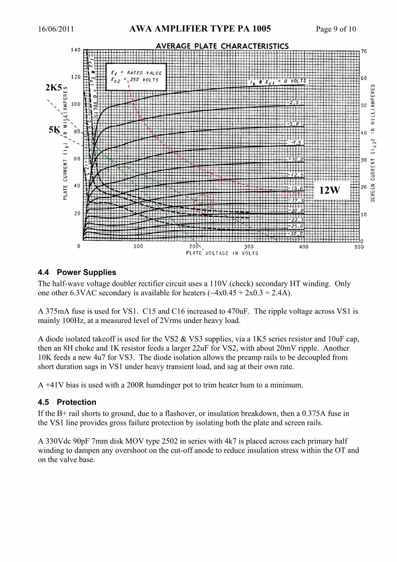
4.3 Output Stage In this Class AB push-pull output stage, two tubes are pushed into conduction and the other two tubes are pulled into cutoff, and there is a region of overlap where all tubes conduct equivalent levels of current. The cathodes are biased to +14V using a common cathode resistor. The 5KΩ impedance plate-to-plate OPT presents each pair of tubes with a 1.25KΩ load impedance (with a matched secondary load) for signal currents in Class B region, and 2.5K in Class A region. Exact replacement for 6AQ5 is 6HG5. Determining a suitable bias current level is not an empirical design approach, rather it is based on the following recommendations:
• Start with the lowest bias current possible (ie. most negative grid bias voltage), and based on listening tests, increase the bias current until the sound character is acceptable, but:
• use the lowest possible bias current level, as this generally increases the life of the tubes, and decreases the chance of operating at excessive plate dissipation; and
• keep the bias current level below 70% of the 12W recommended design max plate dissipation (ie. <8.4W); and
• assess the dynamic loadline to see if it moves into region of increased plate dissipation. As the output loading increases, the supply voltage VS1 to the output valve plates sags from about 245V towards 200V. Plate DC voltage will be lower than VS1 by an amount of 14V to ~44Vpk; ie. OPT half resistance of about 81Ω with a peak current of up to about 0.07+.07A, and 14V+19V(pk) cathode bias. Screen voltage supply will also vary from about 240V towards 200V under steady-state heavy load. Screen voltage lower than VS1 by 12V due to the 390R stopper resistors at 30mA screen current per tube, plus additional 14V+20V(pk) cathode bias voltage increase. Max screen power dissipation is then up to 30mA x 200V = 6Wpk, and screen resistor peak is 0.35Wpk. The 6AQ5 valve bias current allowed is 8.4W / (245-15V) = 36mA. Each valve has an ‘off’ period for 50% of time, where the average plate dissipation is relatively low and expected to be in the range between the upper limit of the bias level power dissipation, down to a few watts when most of the period is spent in deep cutoff due to very negative grid voltage levels. As such, the average dissipation during the ‘on’ period can extend dynamically above the 12W curve. Assessing the 6AQ5 plate curves, which shows the 12W constant power contour, indicate how the amp will dynamically remain well below plate dissipation levels. Note that these curves are for a 250V screen level, with no compression influences. With the screen voltage reduced towards 200V, the knee of the curve will sag down through the 2K5 Class B loadline. Most of the operation is in Class A, with cut-off only occurring at waveform peaks. Assuming the loadline sags to about 200V level and a peak plate current of 70+70=140mA is achieved, then the nominal output power of the amplifier would be: (Ipk)2 x Rpp / 8 = 0.14 x 0.14 x 5k / 8 = 12W. For this maximum signal condition, the rms OPT current draw is likely about 90mA (64% of peak), and the average VS1 power consumed is 220x0.09 =20W, and the OPT loss is (0.09)2 x 162Ω = 1.3W, so the tube plates dissipate 20 - 12 - 1W = 7W, or under 2W each.
16/06/2011 AWA AMPLIFIER TYPE PA 1005 Page 9 of 10
4.4 Power SuppliesThe half-wave voltage doubler rectifier circuit uses a 110V (check) secondary HT winding. Only one other 6.3VAC secondary is available for heaters (~4x0.45 + 2x0.3 = 2.4A).
A 375mA fuse is used for VS1. C15 and C16 increased to 470uF. The ripple voltage across VS1 is mainly 100Hz, at a measured level of 2Vrms under heavy load.
A diode isolated takeoff is used for the VS2 & VS3 supplies, via a 1K5 series resistor and 10uF cap, then an 8H choke and 1K resistor feeds a larger 22uF for VS2, with about 20mV ripple. Another 10K feeds a new 4u7 for VS3. The diode isolation allows the preamp rails to be decoupled from short duration sags in VS1 under heavy transient load, and sag at their own rate.
A +41V bias is used with a 200R humdinger pot to trim heater hum to a minimum.
4.5 ProtectionIf the B+ rail shorts to ground, due to a flashover, or insulation breakdown, then a 0.375A fuse in the VS1 line provides gross failure protection by isolating both the plate and screen rails.
A 330Vdc 90pF 7mm disk MOV type 2502 in series with 4k7 is placed across each primary half winding to dampen any overshoot on the cut-off anode to reduce insulation stress within the OT and on the valve base.
12W
2K5
5K

16/06/2011 AWA AMPLIFIER TYPE PA 1005 Page 10 of 10
Nominal VVR Class B loadlines
2.5K
Nominal idle bias points for VVR levels