Embed Size (px)
Citation preview
s
Process Control System PCS 7 Engineering Compendium Part A Standard Preliminary Draft V2.0
Preface Contents
PC administration 1 Creating and managing a PCS 7 project 2 Configuration of the hardware (AS and I/O) 3 Configuration of the network connections 4
Configuring AS functions 5
Compiling and downloading 6
Configuring OS functions 7 Changing and maintaining projects 8
SIMATIC
Process Control System PCS 7 Engineering Compendium Part A Standard
Manual
02/2008 Preliminary Draft V2.0
Siemens AG Automation and Drives PO Box 4848 90437 NUREMBERG GERMANY
Preliminary Draft V2.0 02/2008
Copyright © Siemens AG 2007 Subject to change.
Safety instructions This manual contains instructions intended to ensure personal safety, as well as to protect equipment against damage. Instructions relating to your personal safety are indicated by a warning triangle, which does not appear with instructions solely relating to material damage. Warning notices appear as shown below, in descending order of hazard priority.
! Danger indicates that death or severe personal injury will result if proper precautions are not taken.
! Warning indicates that death or severe personal injury may result if proper precautions are not taken.
! Caution with a warning triangle indicates that minor personal injury may result if proper precautions are not taken.
Caution without a warning triangle indicates that property damage may result if proper precautions are not taken.
Notice indicates that an unwanted result or state may occur if the relevant instruction is not observed.
If several hazard levels are applicable, the warning notice corresponding to the highest level is always used. If a warning notice with a warning triangle relates to the risk of personal injury, a warning relating to material damage may also be added to that same warning notice.
Qualified personnel The equipment/system to which this documentation applies must always be set up and operated in ac-cordance with this manual. Only qualified personnel should be allowed to commission and work on this equipment/system. The term “qualified personnel”, as used in the safety-related information in this documentation, is defined as persons who are authorized to commission, to ground, and to tag equip-ment, systems, and circuits in accordance with established safety practices and standards.
Correct usage
Note the following:
! Warning The equipment may only be used for the applications described in the catalog and the technical de-scription, and only in conjunction with equipment or components from other manufacturers which have been approved or recommended by Siemens. This product can only function correctly and safely if it is transported, stored, assembled, and installed correctly, and operated and maintained as recom-mended.
Trademarks All product names marked with the ® copyright symbol are trademarks of Siemens AG. Other product names in this document may be trademarks and third parties using these names for their own purposes may infringe upon the rights of the trademark owners.
Disclaimer of liability We have checked the contents of this manual for agreement with the hardware and software described. However, since deviations cannot be precluded entirely, we cannot guarantee full agreement. The in-formation in this manual is reviewed regularly and any necessary corrections will be included in subse-quent editions.
Process Control System PCS 7 Engineering Compendium Part A Standard Preliminary Draft V2.0 iii
Preface
Subject of the manual This manual serves as a design guide, to be used in addition to the SIMATIC PCS 7 product documentation. Essential engineering steps are described in form of operation instructions to a large extent.
Based on practical experience, the suggested solution process is meant to cover general essential needs to avoid frequently occurring problems.
The compendium is divided into three parts:
• Part A Standard
• Part B Process Safety
• Part C Equipment Modules
Parts B and C are based as optional extras for standard part A.
Preface
Process Control System PCS 7 Engineering Compendium Part A Standard iv Preliminary Draft V2.0
Additional support If this manual does not contain the answers to any questions you may have about how to use the products described, please contact your local Siemens representa-tive.
You can locate your contact at:
http://www.siemens.com/automation/partner
The guide that provides details of the technical documentation offered for the indi-vidual SIMATIC products and systems is available at:
http://www.siemens.com/simatic-tech-doku-portal
The online catalog and online ordering system are available at:
http://mall.automation.siemens.com/
Training Center We offer appropriate courses to help you to familiarize yourself with the SIMATIC S7 automation system. Contact your regional Training Center or the Central Train-ing Center in Nuremberg, Germany. Phone: +49 (911) 895-3200. Internet: http://www.sitrain.com
Technical support Technical support for all A&D products can be accessed • Via the online Support Request form at
http://www.siemens.com/automation/support-request • By phone: + 49 180 5050 222 • By fax: + 49 180 5050 223 Additional information on our technical support is available on the Internet at http://www.siemens.com/automation/service
Service & support on the Internet In addition to our documentation options, our expertise is also available to you online. http://www.siemens.com/automation/service&support Here you will be able to access: • The newsletter, which will keep you constantly up-to-date with the latest infor-
mation about our products • The right documents via our Service & Support search facility • A forum that provides users and specialists with an international platform for
exchanging experiences • Your local Automation & Drives representative
• Information about local service, repairs, spare parts And much more is available to you in the “Our service offer” section
Process Control System PCS 7 Engineering Compendium Part A Standard Preliminary Draft V2.0 v
Contents
Preface iii
Contents v
1 PC administration 1-1 1.1 Installation 1-1 1.2 Network settings 1-1 1.2.1 Terminal bus 1-2 1.2.2 Process bus 1-4
2 Creating and managing a PCS 7 project 2-1 2.1 Automatically creating a multiproject 2-2 2.2 Linking other subprojects 2-6 2.3 Arranging components 2-10 2.3.1 Engineering station 2-10 2.3.2 Automation system – Fault-tolerant 2-16 2.3.3 Automation system – Standard 2-17 2.3.4 OS server 2-18 2.3.5 OS clients 2-22 2.4 Settings in the plant hierarchy 2-25 2.5 General project rules 2-30
3 Configuration of the hardware (AS and I/O) 3-1 3.1 CPU settings for plant A with H system 3-1 3.1.1 Startup 3-2 3.1.2 Cycle/Clock Memory 3-3 3.1.3 Process image partitions (PIP) 3-4 3.1.4 Local data requirements 3-6 3.1.5 H Parameters 3-7 3.1.6 Diagnostics/Clock 3-9 3.2 CPU settings for plant B with standard AS 3-10 3.2.1 Startup 3-10 3.2.2 Cycle/Clock Memory 3-11 3.2.3 Process image partitions (PIP) 3-12 3.2.4 Local data requirements 3-13 3.2.5 Diagnostics/Clock 3-14 3.3 Configuration of Industrial Ethernet CP 443-1 3-15 3.3.1 Configuration of the CP 443-1 for plant A with H system 3-15 3.3.2 Configuration of the CP 443-1 for plant B with standard AS 3-17 3.4 PROFIBUS settings on the CP 443-5 Extended 3-19 3.5 Configuration of the ET 200M 3-23 3.5.1 Configuration of the ET 200M for plant A with H system 3-23 3.5.2 Configuration of the ET 200M for plant B with standard AS 3-28 3.5.3 Symbolic names of inputs and outputs 3-33 3.5.4 General rules for configuring I/O modules 3-34 3.6 Configuration in RUN (CiR) 3-39
Contents
Process Control System PCS 7 Engineering Compendium Part A Standard vi Preliminary Draft V2.0
3.6.1 CiR in standard AS 3-39 3.6.2 CiR for H systems (H-CiR) 3-40
4 Configuration of the network connections 4-1 4.1 Merging networks in a multiproject 4-2 4.2 Configuration of connections 4-4 4.2.1 OS-AS connections 4-4 4.2.2 ES-AS connection 4-7 4.2.3 AS-AS connection 4-8 4.3 Downloading connections 4-10
5 Configuring AS functions 5-1 5.1 Basics 5-1 5.1.1 Copying blocks to the master data library 5-1 5.1.2 Changing the message class, priority, and message text 5-2 5.1.3 Changing attributes 5-3 5.1.4 Updating user programs 5-4 5.1.5 Requirements for configuration in CFC 5-5 5.1.6 Driver concept 5-6 5.1.7 Messages from I/O peripherals 5-7 5.2 Creating CFC charts 5-8 5.2.1 Templates 5-8 5.2.2 Run sequence 5-9 5.2.3 Copying templates to the master data library 5-10 5.3 Creating SFC charts 5-11 5.4 Bulk engineering with the Import/Export Assistant 5-12 5.4.1 Import 5-13 5.4.2 Export 5-13 5.4.3 Example 5-14 5.5 Bulk engineering in the process object view 5-19 5.5.1 Functionality 5-19 5.5.2 Example 5-20 5.5.3 Exporting and importing I/Os and messages 5-21
6 Compiling and downloading 6-1 6.1 Compiling the user program 6-1 6.2 Downloading the user program 6-2 6.3 OS compilation 6-3
7 Configuring OS functions 7-1 7.1 Project settings 7-1 7.1.1 Defining the server assignment 7-1 7.1.2 Selecting a preferred server 7-3 7.1.3 Selecting and configuring a standard server 7-4 7.1.4 Working with the OS project editor 7-6 7.1.5 Redundancy settings in the server project 7-8 7.1.6 Time synchronization 7-9 7.2 OS operating and monitoring concept 7-16 7.2.1 Picture hierarchy 7-16 7.2.2 Process pictures 7-18 7.3 OS library 7-20 7.3.1 Block icons/User objects 7-20 7.3.2 Faceplates 7-22 7.3.3 Generating block icons with the SIMATIC Manager 7-23 7.3.4 Wizards 7-25
Contents
Process Control System PCS 7 Engineering Compendium Part A Standard Preliminary Draft V2.0 vii
7.4 Message system 7-26 7.4.1 Message classes and message types 7-26 7.4.2 Message lists 7-28 7.4.3 Acknowledgment concept 7-30 7.4.4 Group display 7-31 7.4.5 Audible interrupt signaling 7-33 7.4.6 Time stamp 7-33 7.5 Archiving 7-34 7.5.1 Tag logging 7-35 7.5.2 Alarm logging 7-36 7.5.3 Central archive server (CAS) 7-37
8 Changing and maintaining projects 8-1 8.1 Compilation and download in process mode 8-1 8.1.1 Manual update procedure during operation 8-1 8.1.2 Automatic update procedure 8-2 8.1.3 Downloading the entire program to a redundant OS server pair 8-3 8.2 Integrated asset management 8-4 8.2.1 Single station system with maintenance station 8-4 8.2.2 Multiple workstation system with MS client on the ES 8-5

Process Control System PCS 7 Engineering Compendium Part A Standard Preliminary Draft V2.0 1-1
1 PC administration
1.1 Installation
The operating system and SIMATIC PCS 7 software are preinstalled on the SIMATIC PCS 7 industrial workstation.
If manual installation is to be performed, observe the relevant requirements and the procedure described in the "PCS 7 Readme" file and the manual titled “Proc-ess Control System PCS 7; PC Configuration and Authorization”.
1.2 Network settings
The settings below must be checked or made following installation.
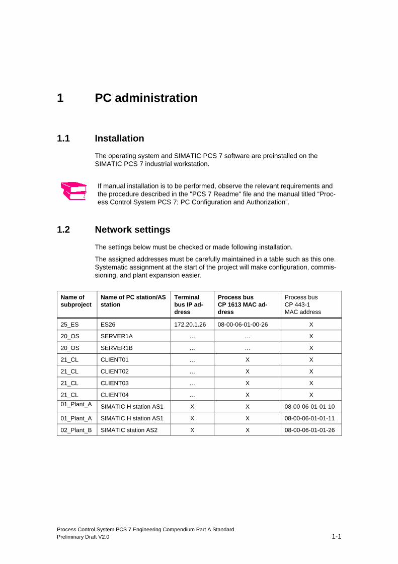
The assigned addresses must be carefully maintained in a table such as this one. Systematic assignment at the start of the project will make configuration, commis-sioning, and plant expansion easier.
Name of subproject
Name of PC station/AS station
Terminal bus IP ad-dress
Process bus CP 1613 MAC ad-dress
Process bus CP 443-1 MAC address
25_ES ES26 172.20.1.26 08-00-06-01-00-26 X
20_OS SERVER1A … … X
20_OS SERVER1B … … X
21_CL CLIENT01 … X X
21_CL CLIENT02 … X X
21_CL CLIENT03 … X X
21_CL CLIENT04 … X X 01_Plant_A SIMATIC H station AS1 X X 08-00-06-01-01-10
01_Plant_A SIMATIC H station AS1 X X 08-00-06-01-01-11
02_Plant_B SIMATIC station AS2 X X 08-00-06-01-01-26
PC administration
Process Control System PCS 7 Engineering Compendium Part A Standard 1-2 Preliminary Draft V2.0
1.2.1 Terminal bus
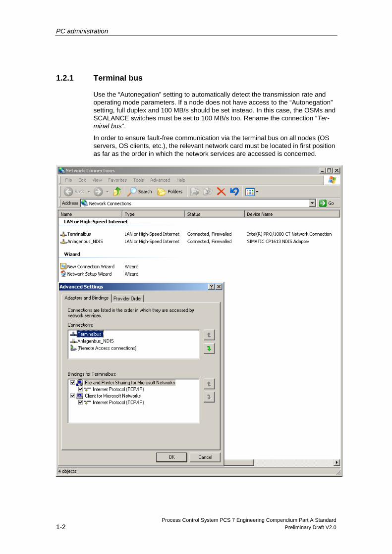
Use the “Autonegation” setting to automatically detect the transmission rate and operating mode parameters. If a node does not have access to the “Autonegation” setting, full duplex and 100 MB/s should be set instead. In this case, the OSMs and SCALANCE switches must be set to 100 MB/s too. Rename the connection “Ter-minal bus".
In order to ensure fault-free communication via the terminal bus on all nodes (OS servers, OS clients, etc.), the relevant network card must be located in first position as far as the order in which the network services are accessed is concerned.
PC administration
Process Control System PCS 7 Engineering Compendium Part A Standard Preliminary Draft V2.0 1-3
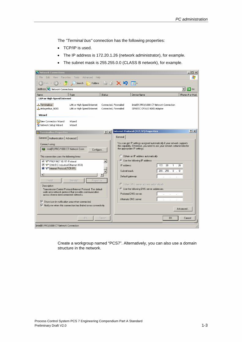
The "Terminal bus" connection has the following properties:
• TCP/IP is used.
• The IP address is 172.20.1.26 (network administrator), for example.
• The subnet mask is 255.255.0.0 (CLASS B network), for example.
Create a workgroup named “PCS7”. Alternatively, you can also use a domain structure in the network.
PC administration
Process Control System PCS 7 Engineering Compendium Part A Standard 1-4 Preliminary Draft V2.0
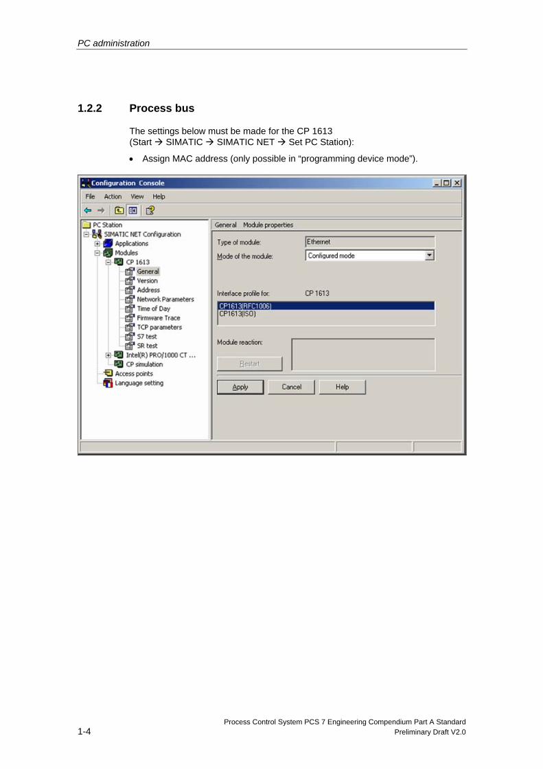
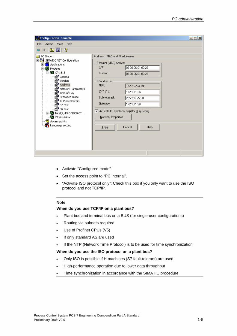
1.2.2 Process bus
The settings below must be made for the CP 1613 (Start SIMATIC SIMATIC NET Set PC Station):
• Assign MAC address (only possible in “programming device mode”).
PC administration
Process Control System PCS 7 Engineering Compendium Part A Standard Preliminary Draft V2.0 1-5
• Activate "Configured mode”.
• Set the access point to “PC internal”.
• “Activate ISO protocol only”: Check this box if you only want to use the ISO protocol and not TCP/IP.
Note
When do you use TCP/IP on a plant bus?
• Plant bus and terminal bus on a BUS (for single-user configurations)
• Routing via subnets required
• Use of Profinet CPUs (V5)
• If only standard AS are used
• If the NTP (Network Time Protocol) is to be used for time synchronization
When do you use the ISO protocol on a plant bus?
• Only ISO is possible if H machines (S7 fault-tolerant) are used
• High-performance operation due to lower data throughput
• Time synchronization in accordance with the SIMATIC procedure

Process Control System PCS 7 Engineering Compendium Part A Standard Preliminary Draft V2.0 2-1
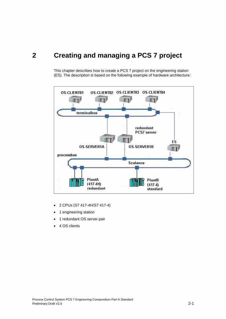
2 Creating and managing a PCS 7 project
This chapter describes how to create a PCS 7 project on the engineering station (ES). The description is based on the following example of hardware architecture:
• 2 CPUs (S7 417-4H/S7 417-4)
• 1 engineering station
• 1 redundant OS server pair
• 4 OS clients
Creating and managing a PCS 7 project
Process Control System PCS 7 Engineering Compendium Part A Standard 2-2 Preliminary Draft V2.0
2.1 Automatically creating a multiproject
With PCS 7 V7.0 we recommend using the “New Project…” wizard to create a mul-tiproject. This wizard automatically creates the necessary project structures so the user can immediately start work on actually engineering the plant.
Our sample project “Chemistry_MP” is to consist of the following parts:
• Subproject “25_ES” for the ES
• Subproject “20_OS” for the redundant OS server pair
• Subproject “21_CL” for the OS clients
• Subproject “01_PLANT_A” for the fault-tolerant AS
• Subproject “02_PLANT_B” for the standard AS
• Master data library “Chemistry_Lib”
The multiproject is divided into various subprojects in accordance with technological and local, as well as project-specific, conditions, such as the number of project engineers, or job-specific ones (definition of responsibilities) in order to improve transparency and plant and system safety during creation of the project. It would also be possible, for example, to integrate all PC stations into one subpro-ject.
In this example, all projects are configured on a single ES. You will find information on distributed engineering in the manual titled “Process Control System PCS 7; Engineering System”.
Before starting work, define a directory in which all PCS 7 projects are saved. Sys-tem and project data should be saved separately in the interests of data integrity. We recommend that you create a separate directory on the data partition.
Creating and managing a PCS 7 project
Process Control System PCS 7 Engineering Compendium Part A Standard Preliminary Draft V2.0 2-3
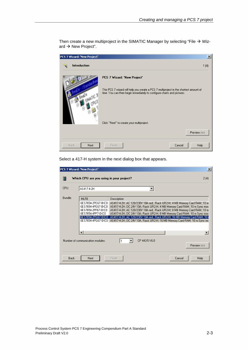
Then create a new multiproject in the SIMATIC Manager by selecting “File Wiz-ard New Project”.
Select a 417-H system in the next dialog box that appears.
Creating and managing a PCS 7 project
Process Control System PCS 7 Engineering Compendium Part A Standard 2-4 Preliminary Draft V2.0
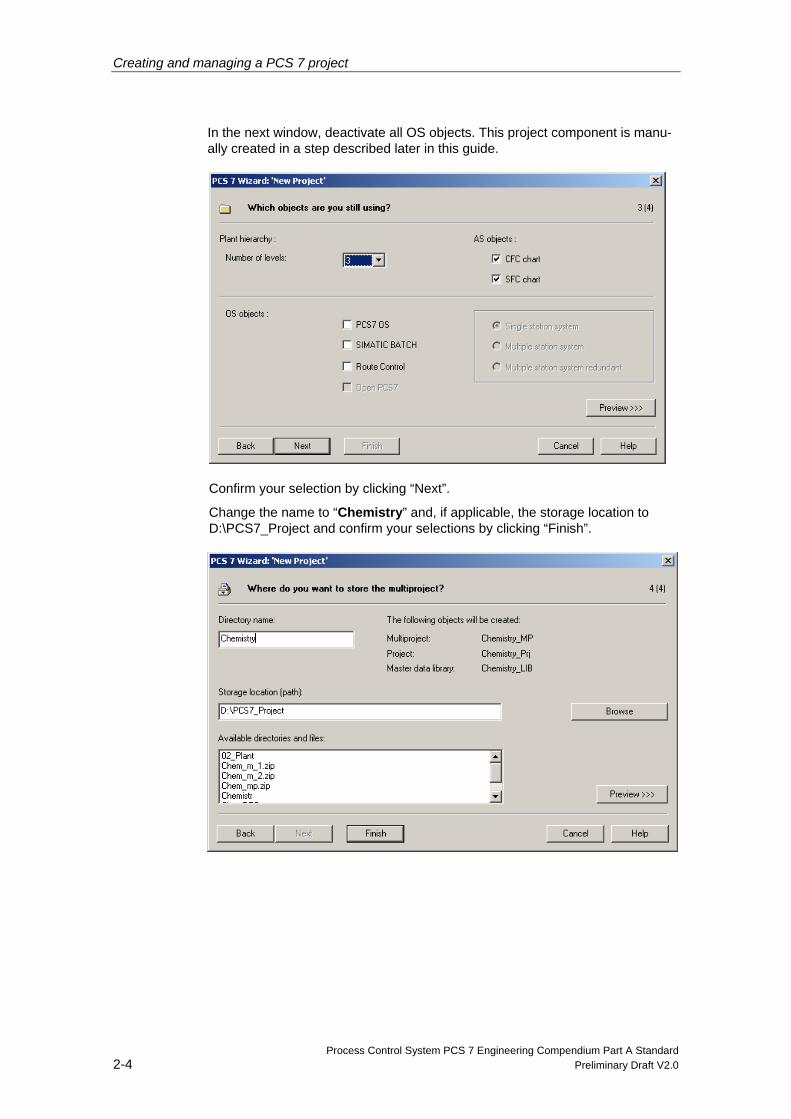
In the next window, deactivate all OS objects. This project component is manu-ally created in a step described later in this guide.
Confirm your selection by clicking “Next”.
Change the name to “Chemistry” and, if applicable, the storage location to D:\PCS7_Project and confirm your selections by clicking “Finish”.
Creating and managing a PCS 7 project
Process Control System PCS 7 Engineering Compendium Part A Standard Preliminary Draft V2.0 2-5
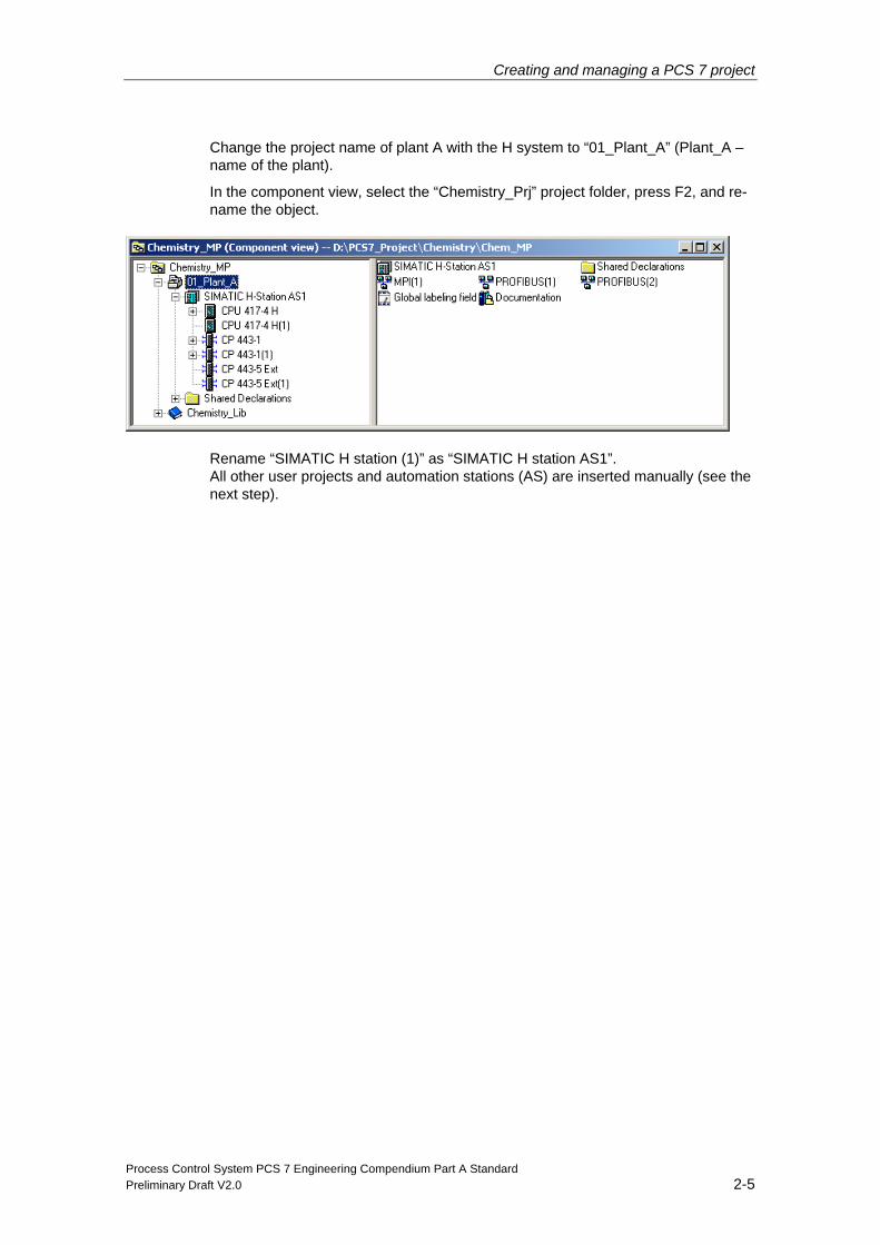
Change the project name of plant A with the H system to “01_Plant_A” (Plant_A – name of the plant).
In the component view, select the “Chemistry_Prj” project folder, press F2, and re-name the object.
Rename “SIMATIC H station (1)” as “SIMATIC H station AS1”. All other user projects and automation stations (AS) are inserted manually (see the next step).
Creating and managing a PCS 7 project
Process Control System PCS 7 Engineering Compendium Part A Standard 2-6 Preliminary Draft V2.0
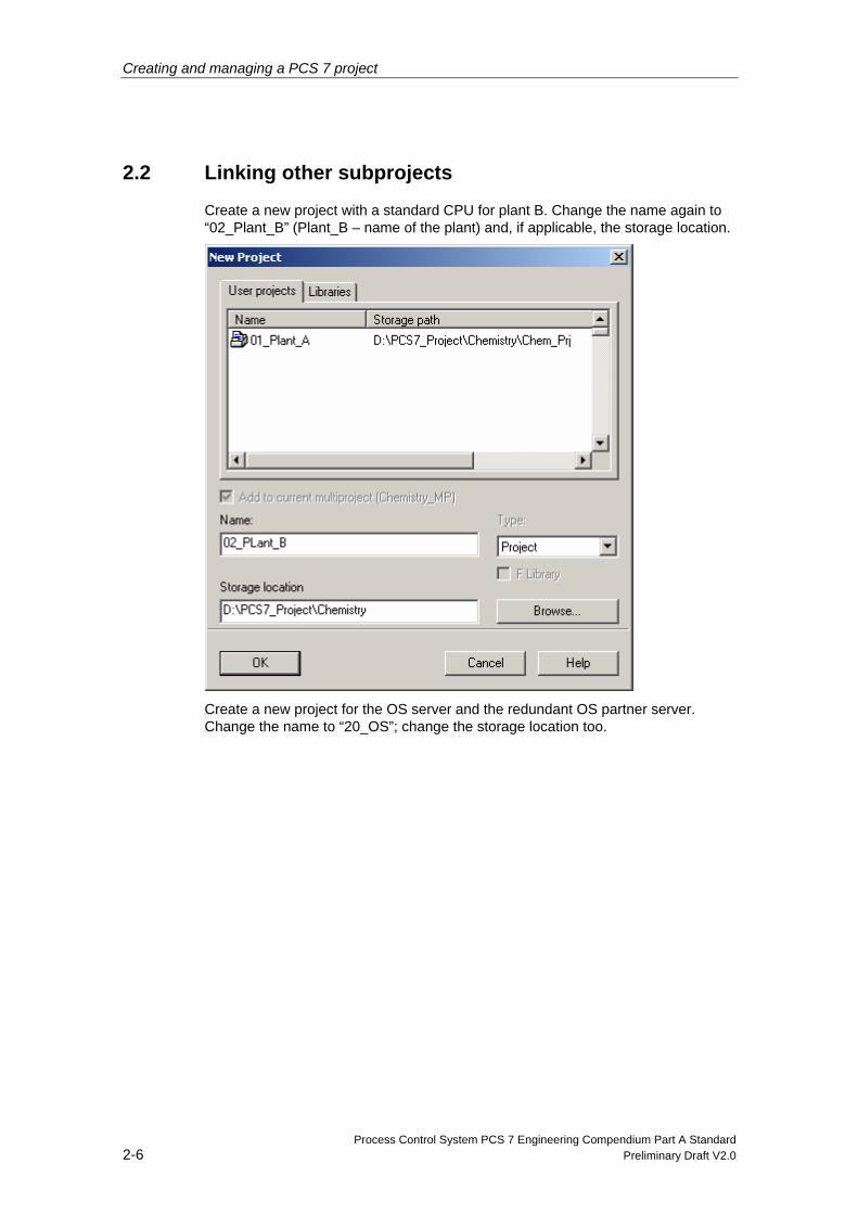
2.2 Linking other subprojects
Create a new project with a standard CPU for plant B. Change the name again to “02_Plant_B” (Plant_B – name of the plant) and, if applicable, the storage location.
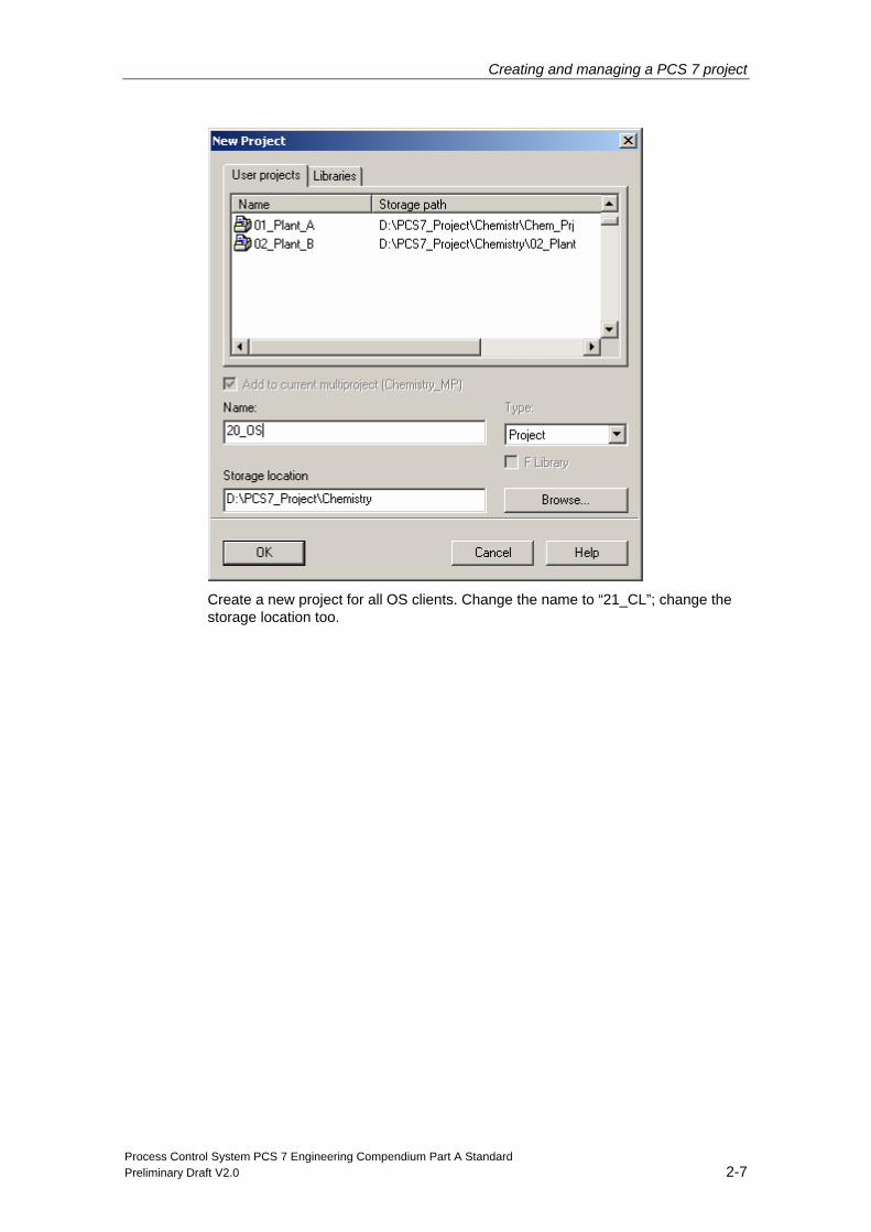
Create a new project for the OS server and the redundant OS partner server. Change the name to “20_OS”; change the storage location too.
Creating and managing a PCS 7 project
Process Control System PCS 7 Engineering Compendium Part A Standard Preliminary Draft V2.0 2-7
Create a new project for all OS clients. Change the name to “21_CL”; change the storage location too.
Creating and managing a PCS 7 project
Process Control System PCS 7 Engineering Compendium Part A Standard 2-8 Preliminary Draft V2.0
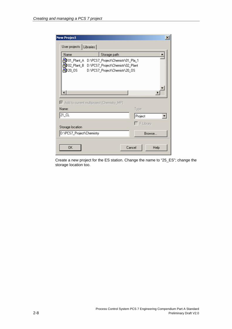
Create a new project for the ES station. Change the name to “25_ES”; change the storage location too.
Creating and managing a PCS 7 project
Process Control System PCS 7 Engineering Compendium Part A Standard Preliminary Draft V2.0 2-9
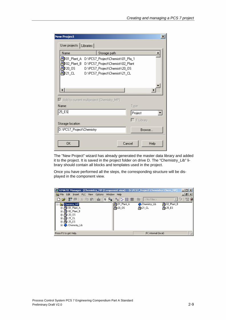
The "New Project" wizard has already generated the master data library and added it to the project. It is saved in the project folder on drive D. The “Chemistry_Lib” li-brary should contain all blocks and templates used in the project.
Once you have performed all the steps, the corresponding structure will be dis-played in the component view.
Creating and managing a PCS 7 project
Process Control System PCS 7 Engineering Compendium Part A Standard 2-10 Preliminary Draft V2.0
2.3 Arranging components
Once the projects have been created, you must arrange the automation stations (AS) and PC stations in accordance with the plant’s hardware configuration.
First configure the ES PC station as shown below.
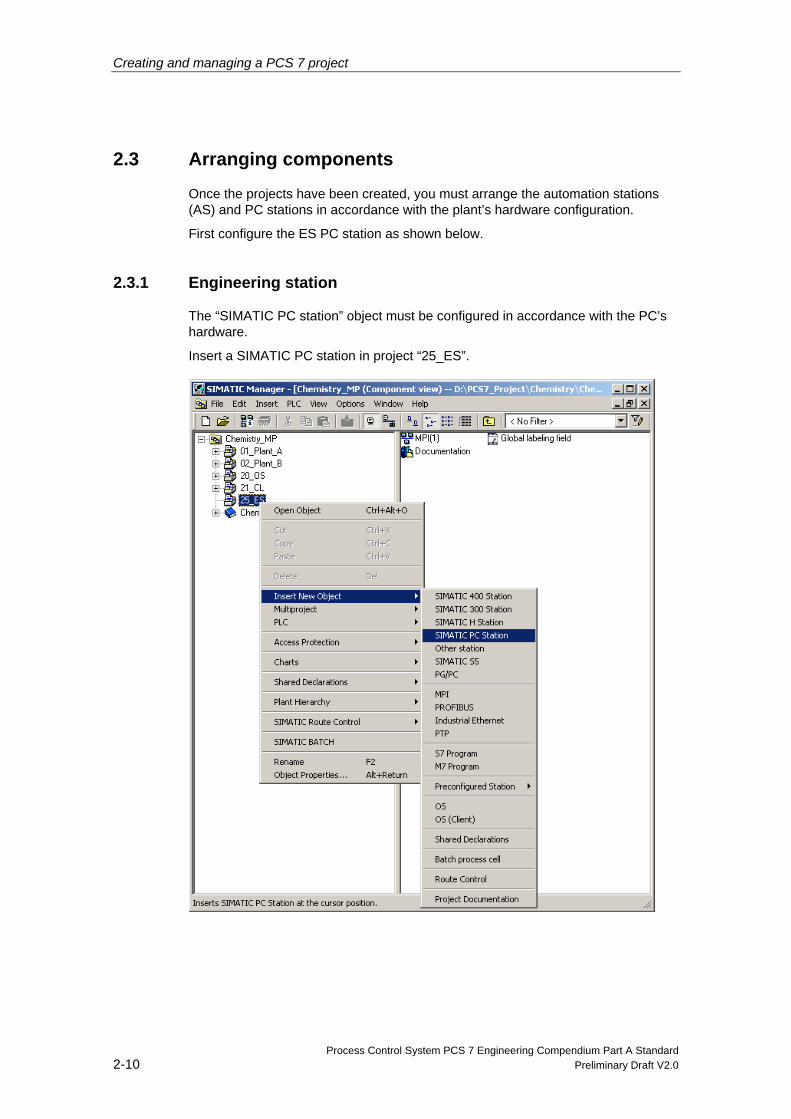
2.3.1 Engineering station
The “SIMATIC PC station” object must be configured in accordance with the PC’s hardware.
Insert a SIMATIC PC station in project “25_ES”.
Creating and managing a PCS 7 project
Process Control System PCS 7 Engineering Compendium Part A Standard Preliminary Draft V2.0 2-11
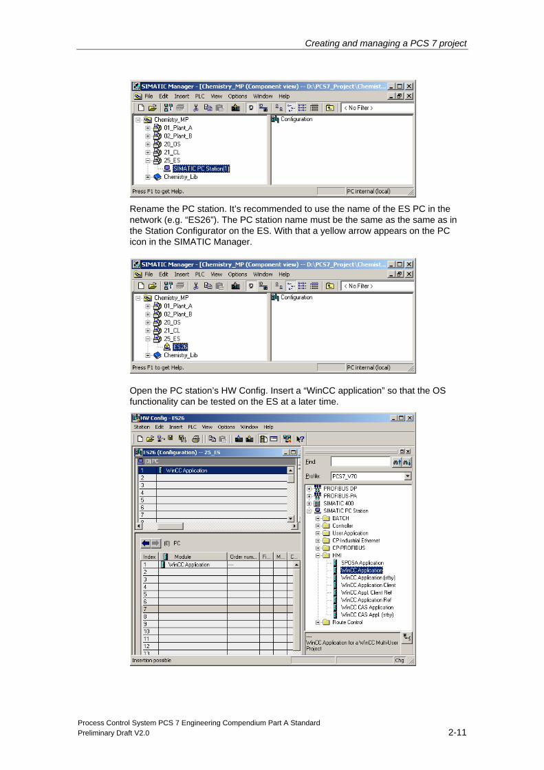
Rename the PC station. It’s recommended to use the name of the ES PC in the network (e.g. “ES26”). The PC station name must be the same as the same as in the Station Configurator on the ES. With that a yellow arrow appears on the PC icon in the SIMATIC Manager.
Open the PC station’s HW Config. Insert a “WinCC application” so that the OS functionality can be tested on the ES at a later time.
Creating and managing a PCS 7 project
Process Control System PCS 7 Engineering Compendium Part A Standard 2-12 Preliminary Draft V2.0
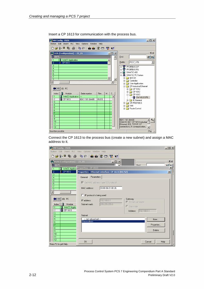
Insert a CP 1613 for communication with the process bus.
Connect the CP 1613 to the process bus (create a new subnet) and assign a MAC address to it.
Creating and managing a PCS 7 project
Process Control System PCS 7 Engineering Compendium Part A Standard Preliminary Draft V2.0 2-13
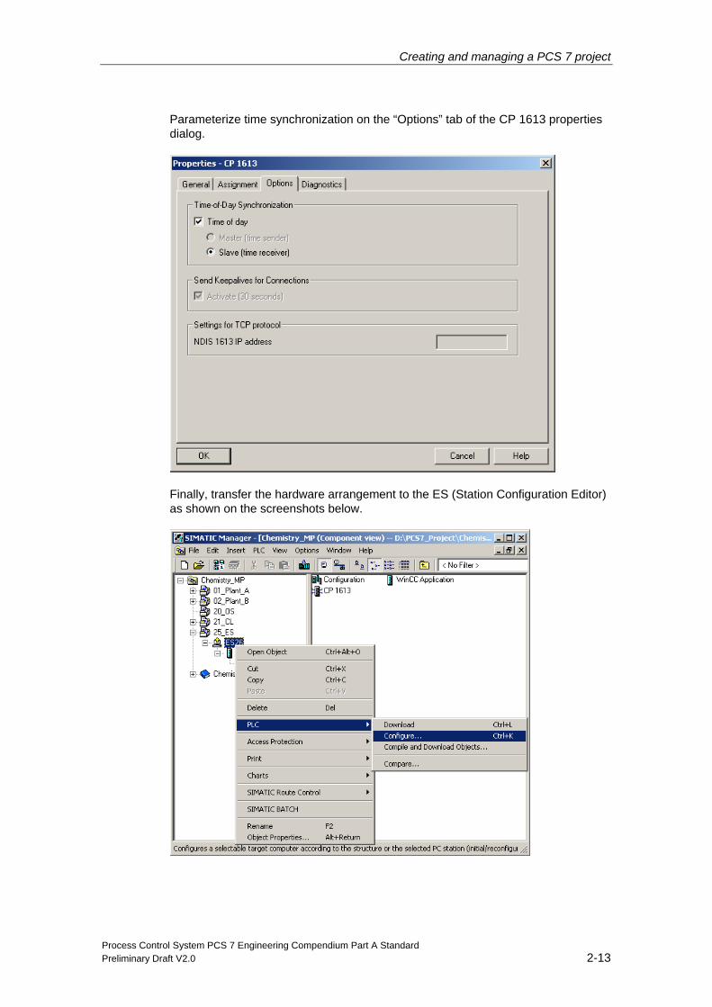
Parameterize time synchronization on the “Options” tab of the CP 1613 properties dialog.
Finally, transfer the hardware arrangement to the ES (Station Configuration Editor) as shown on the screenshots below.
Creating and managing a PCS 7 project
Process Control System PCS 7 Engineering Compendium Part A Standard 2-14 Preliminary Draft V2.0
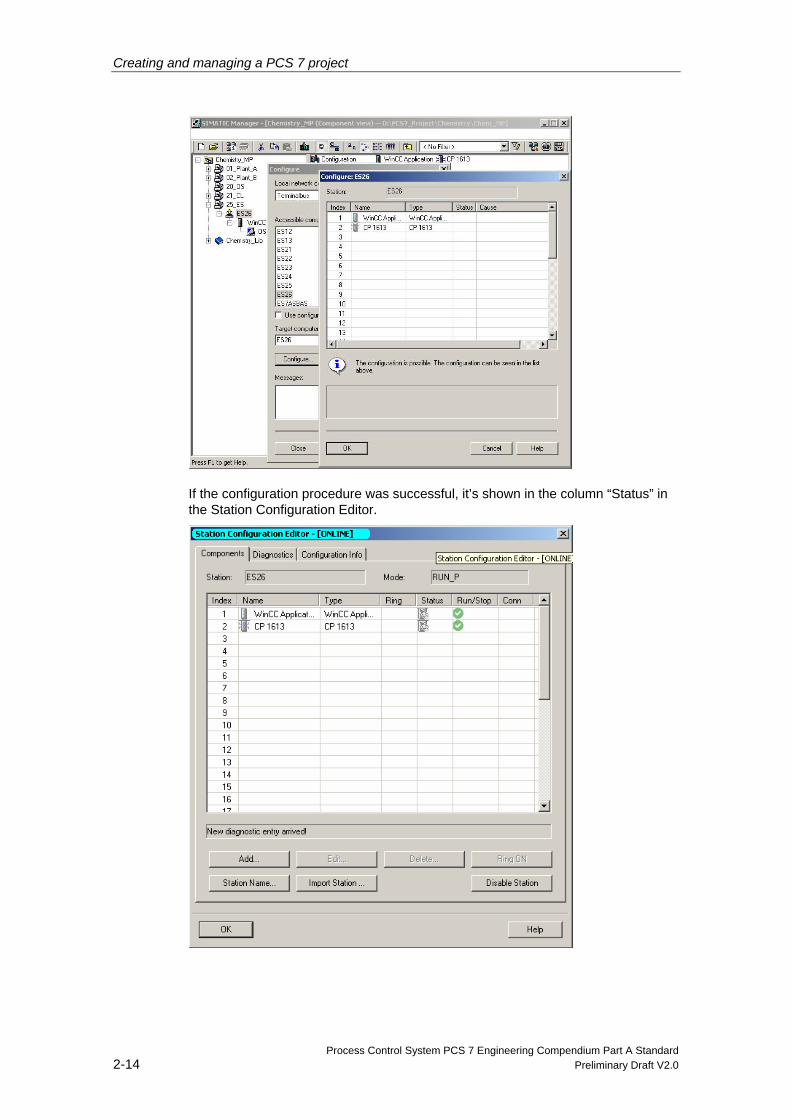
If the configuration procedure was successful, it’s shown in the column “Status” in the Station Configuration Editor.
Creating and managing a PCS 7 project
Process Control System PCS 7 Engineering Compendium Part A Standard Preliminary Draft V2.0 2-15
Using a CP 1613 in the engineering station has the following benefits:
2. More than 8 AS can be connected to the CP 1613.
3. Fault-tolerant connections can be configured (H machine, automatic communication switchover).
4. The CP 1613 MAC address can be parameterized/modified.
5. The “OS simulation” function can also be used for a redundant automation sys-tem.
Note
Using a BCE (Basic Communication Ethernet) for communication rather than the CP 1613 has the following disadvantages:
• The MAC address is fixed and cannot be parameterized.
• This means that, in the event of an error (faulty module), the connections will be reconfigured by means of the new MAC address of the replacement module.
• Modification of relevant documentation!
Creating and managing a PCS 7 project
Process Control System PCS 7 Engineering Compendium Part A Standard 2-16 Preliminary Draft V2.0
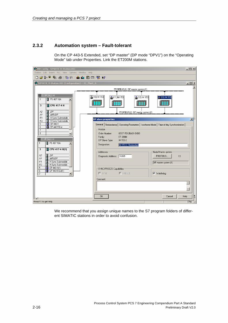
2.3.2 Automation system – Fault-tolerant
On the CP 443-5 Extended, set “DP master” (DP mode “DPV1”) on the “Operating Mode” tab under Properties. Link the ET200M stations.
We recommend that you assign unique names to the S7 program folders of differ-ent SIMATIC stations in order to avoid confusion.
Creating and managing a PCS 7 project
Process Control System PCS 7 Engineering Compendium Part A Standard Preliminary Draft V2.0 2-17
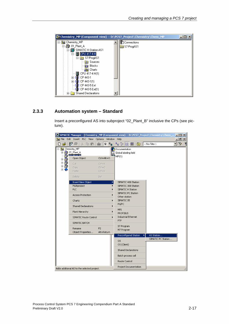
2.3.3 Automation system – Standard
Insert a preconfigured AS into subproject “02_Plant_B” inclusive the CPs (see pic-ture).
Creating and managing a PCS 7 project
Process Control System PCS 7 Engineering Compendium Part A Standard 2-18 Preliminary Draft V2.0
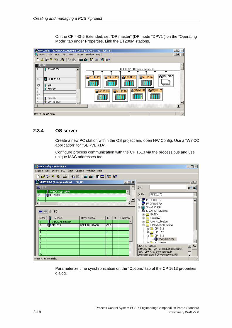
On the CP 443-5 Extended, set “DP master” (DP mode “DPV1”) on the “Operating Mode” tab under Properties. Link the ET200M stations.
2.3.4 OS server
Create a new PC station within the OS project and open HW Config. Use a “WinCC application” for “SERVER1A”.
Configure process communication with the CP 1613 via the process bus and use unique MAC addresses too.
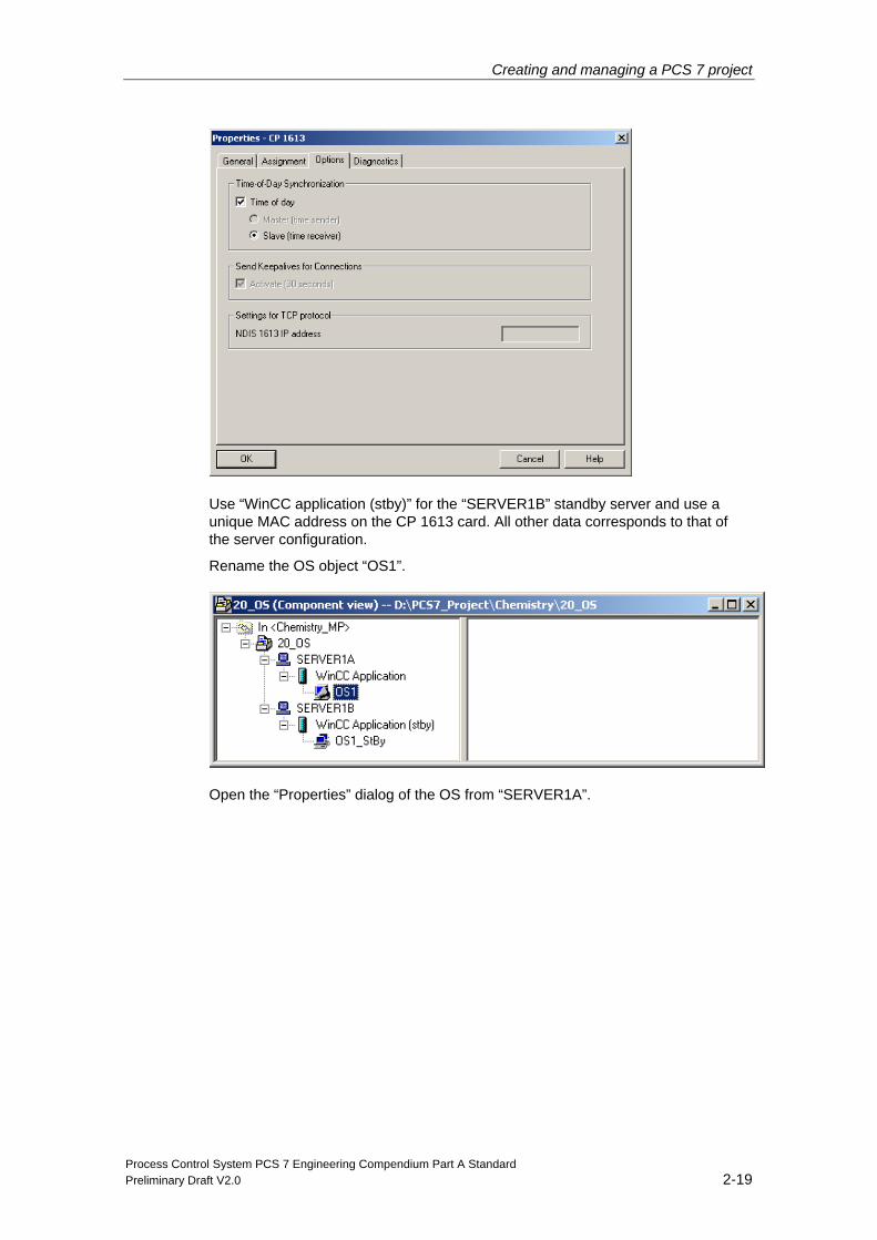
Parameterize time synchronization on the “Options” tab of the CP 1613 properties dialog.
Creating and managing a PCS 7 project
Process Control System PCS 7 Engineering Compendium Part A Standard Preliminary Draft V2.0 2-19
Use “WinCC application (stby)” for the “SERVER1B” standby server and use a unique MAC address on the CP 1613 card. All other data corresponds to that of the server configuration.
Rename the OS object “OS1”.
Open the “Properties” dialog of the OS from “SERVER1A”.
Creating and managing a PCS 7 project
Process Control System PCS 7 Engineering Compendium Part A Standard 2-20 Preliminary Draft V2.0
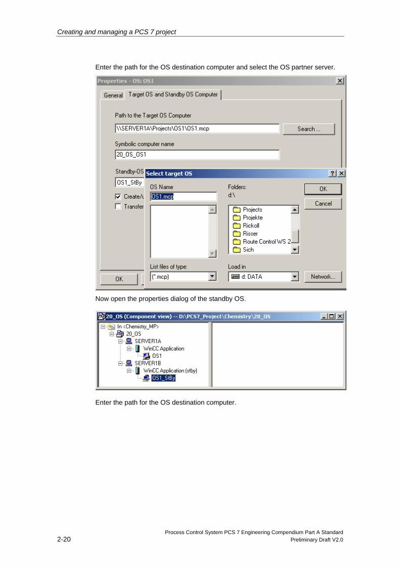
Enter the path for the OS destination computer and select the OS partner server.
Now open the properties dialog of the standby OS.
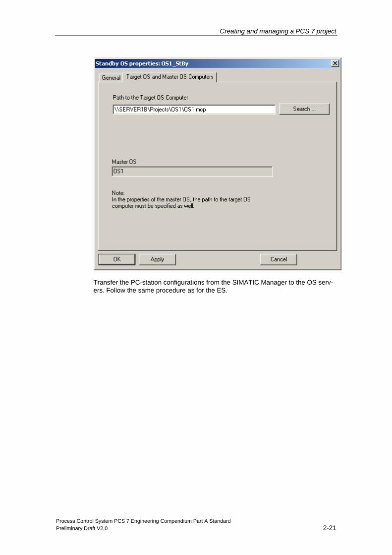
Enter the path for the OS destination computer.
Creating and managing a PCS 7 project
Process Control System PCS 7 Engineering Compendium Part A Standard Preliminary Draft V2.0 2-21
Transfer the PC-station configurations from the SIMATIC Manager to the OS serv-ers. Follow the same procedure as for the ES.

Creating and managing a PCS 7 project
Process Control System PCS 7 Engineering Compendium Part A Standard 2-22 Preliminary Draft V2.0
2.3.5 OS clients
If there are several identical clients, a “WinCC application client” is configured first. This then serves as the basis for the other clients ("WinCC app ref").
One “WinCC appl. client ref” is then configured for each client.
Creating and managing a PCS 7 project
Process Control System PCS 7 Engineering Compendium Part A Standard Preliminary Draft V2.0 2-23
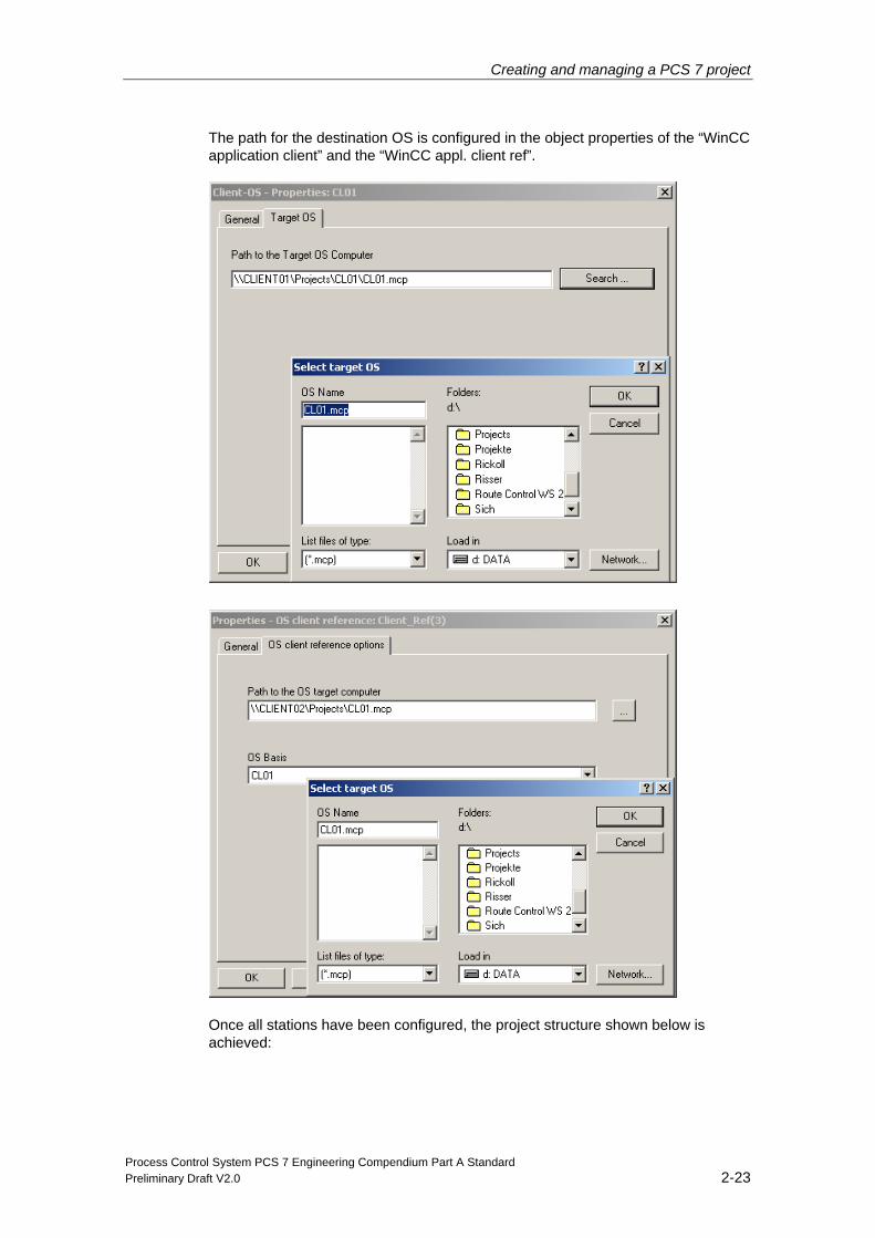
The path for the destination OS is configured in the object properties of the “WinCC application client” and the “WinCC appl. client ref”.
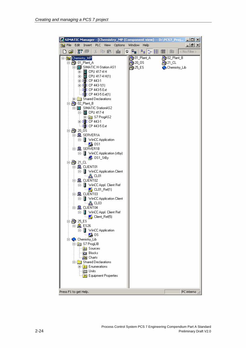
Once all stations have been configured, the project structure shown below is achieved:
Creating and managing a PCS 7 project
Process Control System PCS 7 Engineering Compendium Part A Standard 2-24 Preliminary Draft V2.0
Creating and managing a PCS 7 project
Process Control System PCS 7 Engineering Compendium Part A Standard Preliminary Draft V2.0 2-25
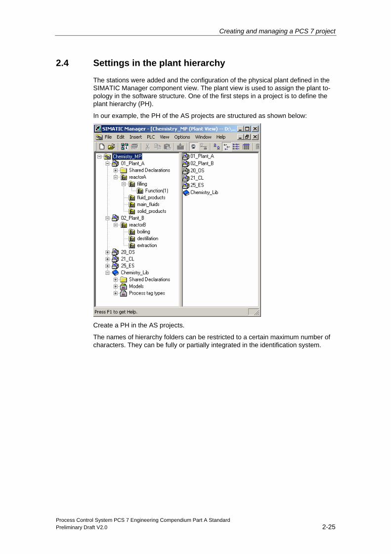
2.4 Settings in the plant hierarchy
The stations were added and the configuration of the physical plant defined in the SIMATIC Manager component view. The plant view is used to assign the plant to-pology in the software structure. One of the first steps in a project is to define the plant hierarchy (PH).
In our example, the PH of the AS projects are structured as shown below:
Create a PH in the AS projects.
The names of hierarchy folders can be restricted to a certain maximum number of characters. They can be fully or partially integrated in the identification system.
Creating and managing a PCS 7 project
Process Control System PCS 7 Engineering Compendium Part A Standard 2-26 Preliminary Draft V2.0
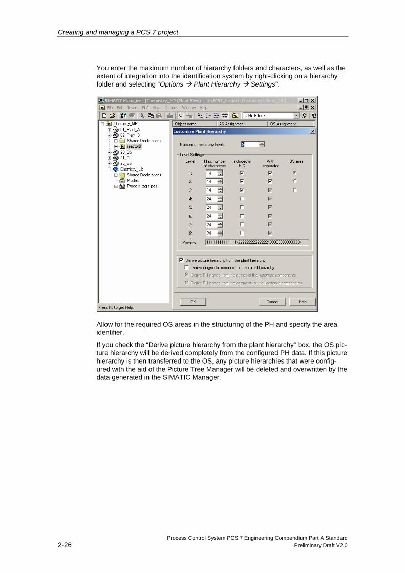
You enter the maximum number of hierarchy folders and characters, as well as the extent of integration into the identification system by right-clicking on a hierarchy folder and selecting “Options Plant Hierarchy Settings”.
Allow for the required OS areas in the structuring of the PH and specify the area identifier.
If you check the “Derive picture hierarchy from the plant hierarchy” box, the OS pic-ture hierarchy will be derived completely from the configured PH data. If this picture hierarchy is then transferred to the OS, any picture hierarchies that were config-ured with the aid of the Picture Tree Manager will be deleted and overwritten by the data generated in the SIMATIC Manager.
Creating and managing a PCS 7 project
Process Control System PCS 7 Engineering Compendium Part A Standard Preliminary Draft V2.0 2-27
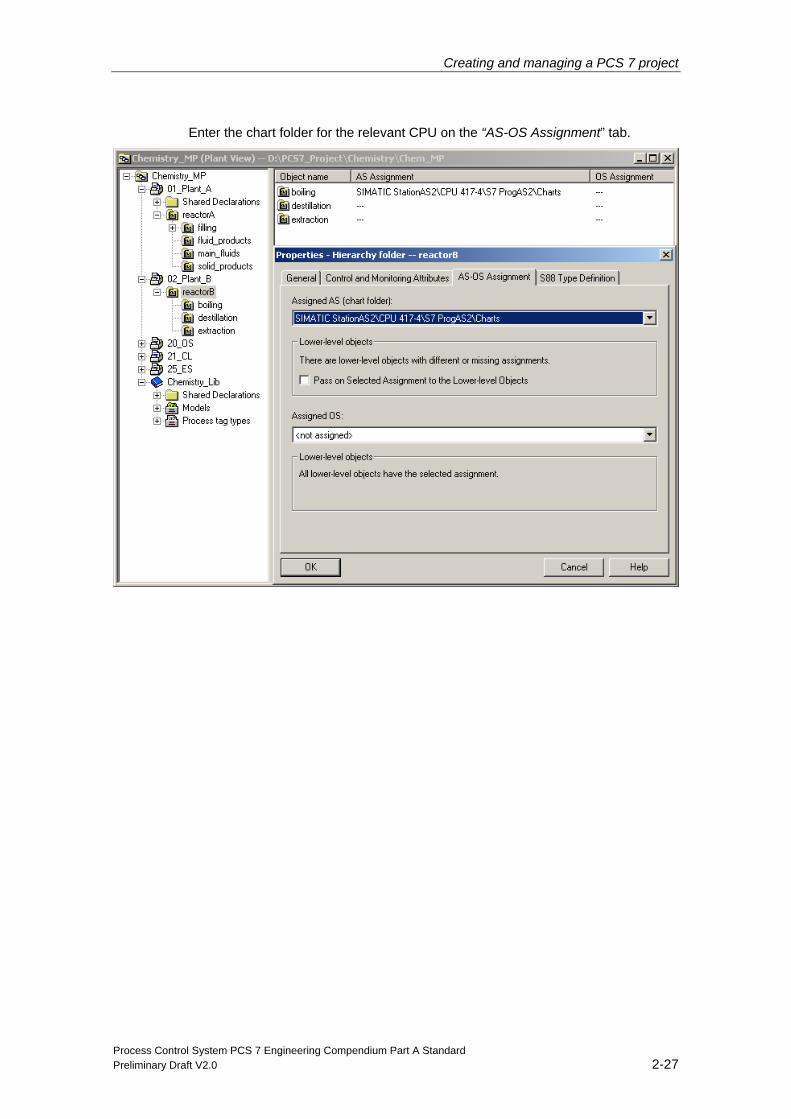
Enter the chart folder for the relevant CPU on the “AS-OS Assignment” tab.
Creating and managing a PCS 7 project
Process Control System PCS 7 Engineering Compendium Part A Standard 2-28 Preliminary Draft V2.0
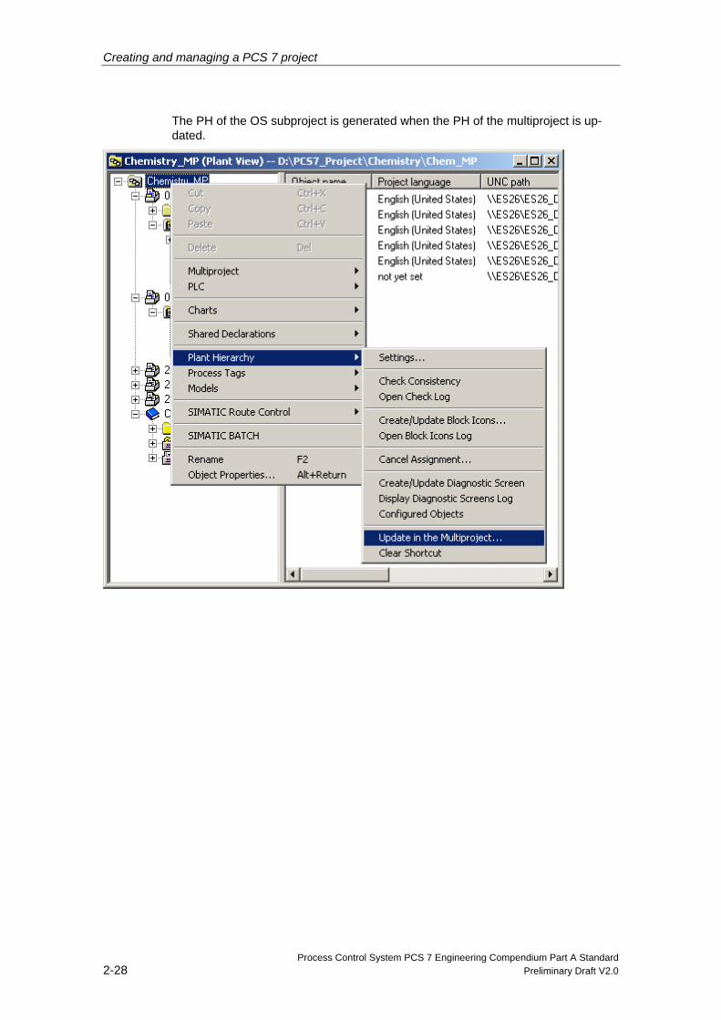
The PH of the OS subproject is generated when the PH of the multiproject is up-dated.
Creating and managing a PCS 7 project
Process Control System PCS 7 Engineering Compendium Part A Standard Preliminary Draft V2.0 2-29
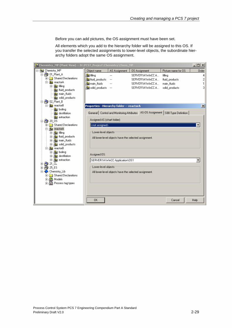
Before you can add pictures, the OS assignment must have been set.
All elements which you add to the hierarchy folder will be assigned to this OS. If you transfer the selected assignments to lower-level objects, the subordinate hier-archy folders adopt the same OS assignment.
Creating and managing a PCS 7 project
Process Control System PCS 7 Engineering Compendium Part A Standard 2-30 Preliminary Draft V2.0
2.5 General project rules
Before you create your own PCS 7 project, you should be familiar with some im-portant rules. This will help you to avoid carrying out certain tasks twice.
• The names of PCs and OS projects, as well as the addresses (MAC, TCP/IP, PROFIBUS) used in the guide must be replaced by the names and addresses used in your system.
• All engineering work must be carried out on the engineering station in PCS 7 before you download the OS project to the PCs. Do not perform any engineer-ing steps on the OS servers or OS clients. The one exception to this rule arises when activating time synchronization for the servers. If the engineering station does not have access to a CP 1613, it cannot be selected on the ES. Therefore, it must be selected on the server it-self.
• Do not activate the OS project on the engineering station. The OS project can be called in simulation mode using the “Start OS simulation” option. In this case, the OS project is duplicated on the ES and the copy is activated. Online access requires a connection to be available between the ES and the OS in NETPRO.
• Do not forget to back up the entire project (or multiproject) at regular intervals, particularly if it is being edited by more than one person. (A backup should be created once a day while engineering is being performed.)
• Use the master data library for the project and ensure that all those editing the project use the blocks and templates from this library.
• Time synchronization is extremely important for the alarm and tag logging sys-tem. Make sure that only one (redundant) time server is present in the system and that all stations (PCs and CPUs) use the correct time. In PCS 7 V7.0 the CPU always uses GMT.
Process Control System PCS 7 Engineering Compendium Part A Standard Preliminary Draft V2.0 3-1
3 Configuration of the hardware (AS and I/O)
This chapter describes the settings in the hardware configuration (HW Config) of the sample project (“Chemistry_MP”).
The screenshots provide an overview of the properties of an H system with CPU 417-4H and CP 443-1/CP 443-5 Extended as well as of a standard AS with CPU 417-4 and CP 443-1/CP 443-5 Extended. The properties dialogs of other CPUs or CPs may be slightly different.
Please note that the routing functionality required to use PDM within the project is only ensured by means of a master system with CP 443-5 Extended. A master sys-tem on the CPU DP interface does not provide this routing functionality.
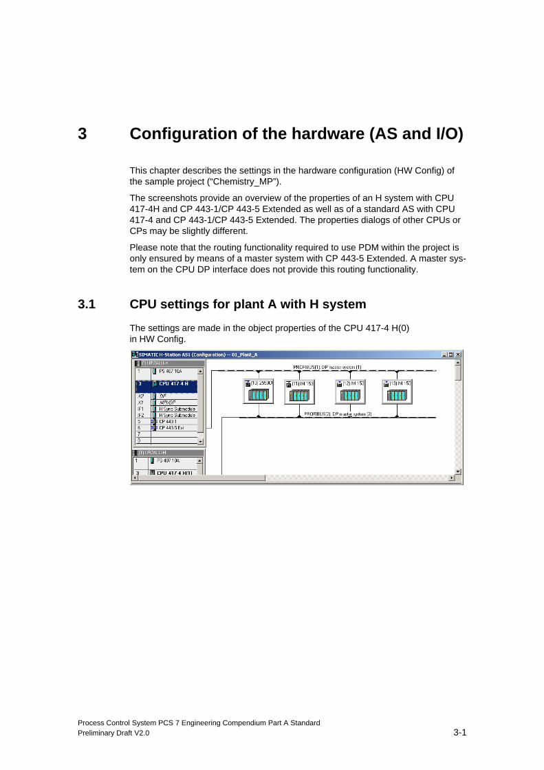
3.1 CPU settings for plant A with H system
The settings are made in the object properties of the CPU 417-4 H(0) in HW Config.
Configuration of the hardware (AS and I/O)
Process Control System PCS 7 Engineering Compendium Part A Standard 3-2 Preliminary Draft V2.0
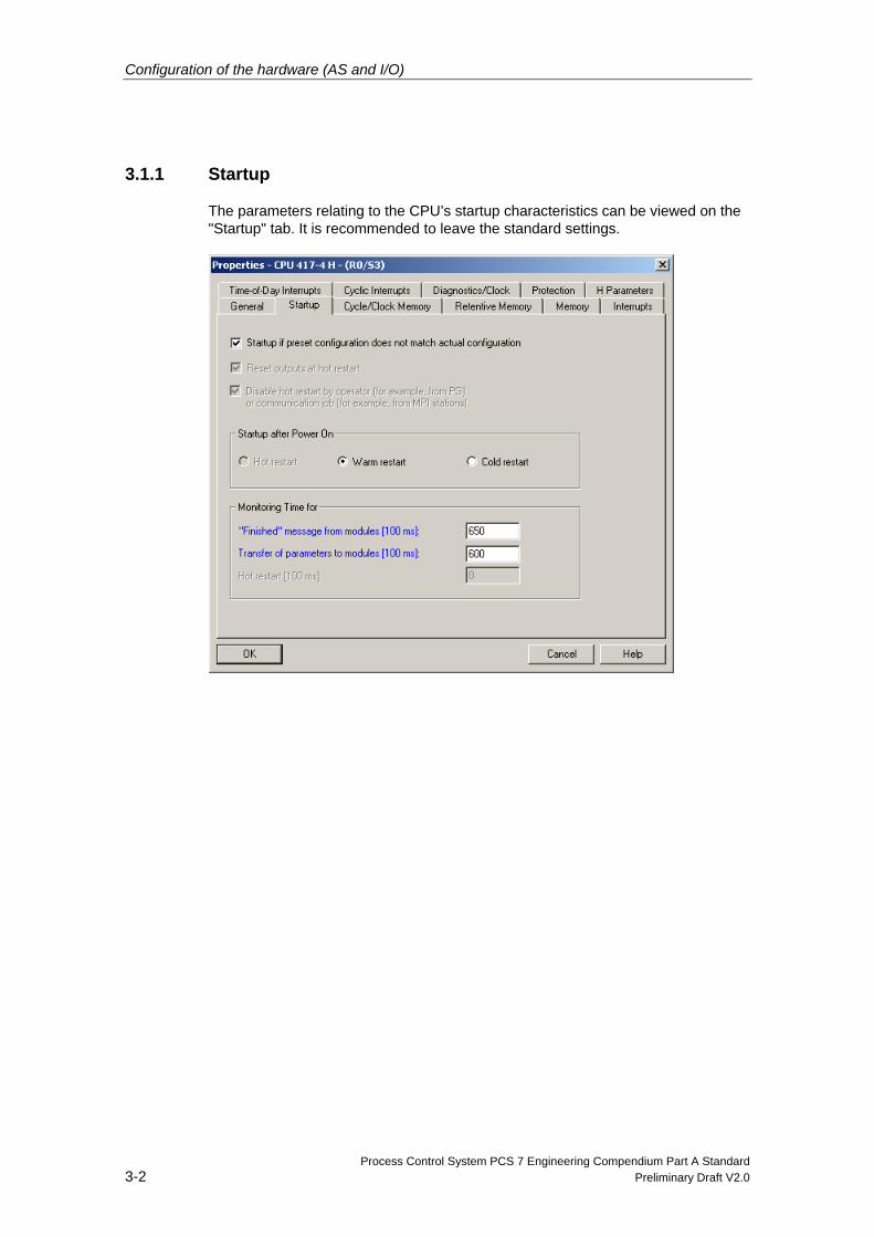
3.1.1 Startup
The parameters relating to the CPU’s startup characteristics can be viewed on the "Startup" tab. It is recommended to leave the standard settings.
Configuration of the hardware (AS and I/O)
Process Control System PCS 7 Engineering Compendium Part A Standard Preliminary Draft V2.0 3-3
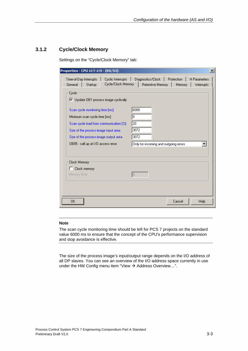
3.1.2 Cycle/Clock Memory
Settings on the “Cycle/Clock Memory” tab:
Note
The scan cycle monitoring time should be left for PCS 7 projects on the standard value 6000 ms to ensure that the concept of the CPU's performance supervision and stop avoidance is effective.
The size of the process image’s input/output range depends on the I/O address of all DP slaves. You can see an overview of the I/O address space currently in use under the HW Config menu item “View Address Overview…”.
Configuration of the hardware (AS and I/O)
Process Control System PCS 7 Engineering Compendium Part A Standard 3-4 Preliminary Draft V2.0
3.1.3 Process image partitions (PIP)
Note The settings below are not required for failsafe applications, as no process image partitions are used in them (see “Engineering Compendium - Part B - Process Safety”).
Using process image partitions
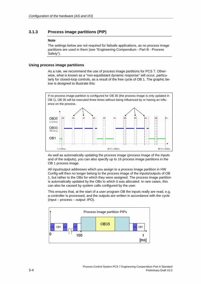
As a rule, we recommend the use of process image partitions for PCS 7. Other-wise, what is known as a “non-equidistant dynamic response” will occur, particu-larly for closed-loop controls, as a result of the free cycle of OB 1. The graphic be-low is designed to illustrate this:
If no process image partition is configured for OB 35 (the process image is only updated in OB 1), OB 35 will be executed three times without being influenced by or having an influ-ence on the process.
As well as automatically updating the process image (process image of the inputs and of the outputs), you can also specify up to 16 process image partitions in the OB 1 process image.
All input/output addresses which you assign to a process image partition in HW Config will then no longer belong to the process image of the inputs/outputs of OB 1, but rather to the OBs for which they were assigned. The process image partition is automatically updated by the OBs to which it was allocated. In rare cases, this can also be caused by system calls configured by the user.
This ensures that, at the start of a user program OB the inputs really are read, e.g. a controller is processed, and the outputs are written in accordance with the cycle (input – process – output: IPO).
Process image partition PIPx
Configuration of the hardware (AS and I/O)
Process Control System PCS 7 Engineering Compendium Part A Standard Preliminary Draft V2.0 3-5
Note You can find background information about the relationship between process im-ages and process image partitions in “Process Control System PCS 7; Engineer-ing Manual”, Chapter 7.8.5.8 “Setting the process image”.
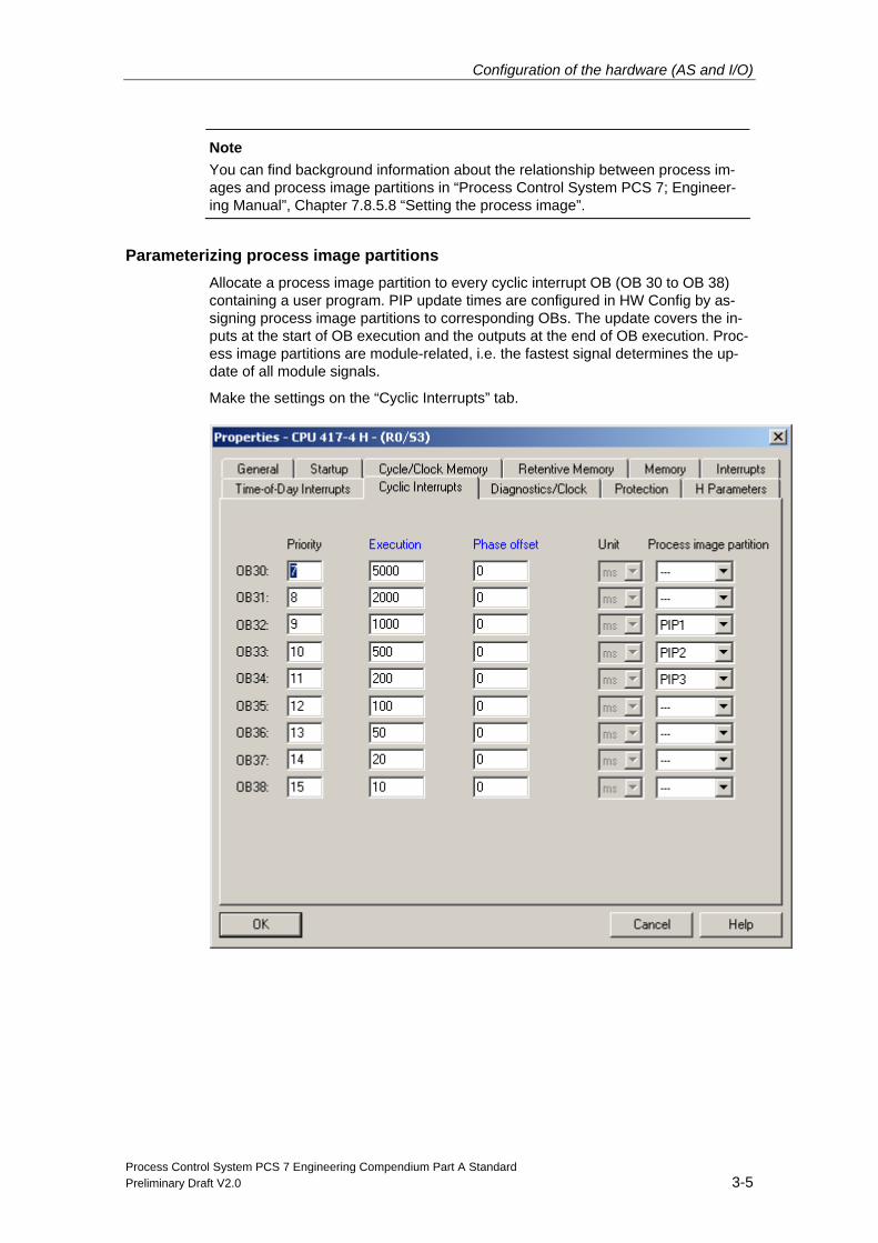
Parameterizing process image partitions
Allocate a process image partition to every cyclic interrupt OB (OB 30 to OB 38) containing a user program. PIP update times are configured in HW Config by as-signing process image partitions to corresponding OBs. The update covers the in-puts at the start of OB execution and the outputs at the end of OB execution. Proc-ess image partitions are module-related, i.e. the fastest signal determines the up-date of all module signals.
Make the settings on the “Cyclic Interrupts” tab.
Configuration of the hardware (AS and I/O)
Process Control System PCS 7 Engineering Compendium Part A Standard 3-6 Preliminary Draft V2.0
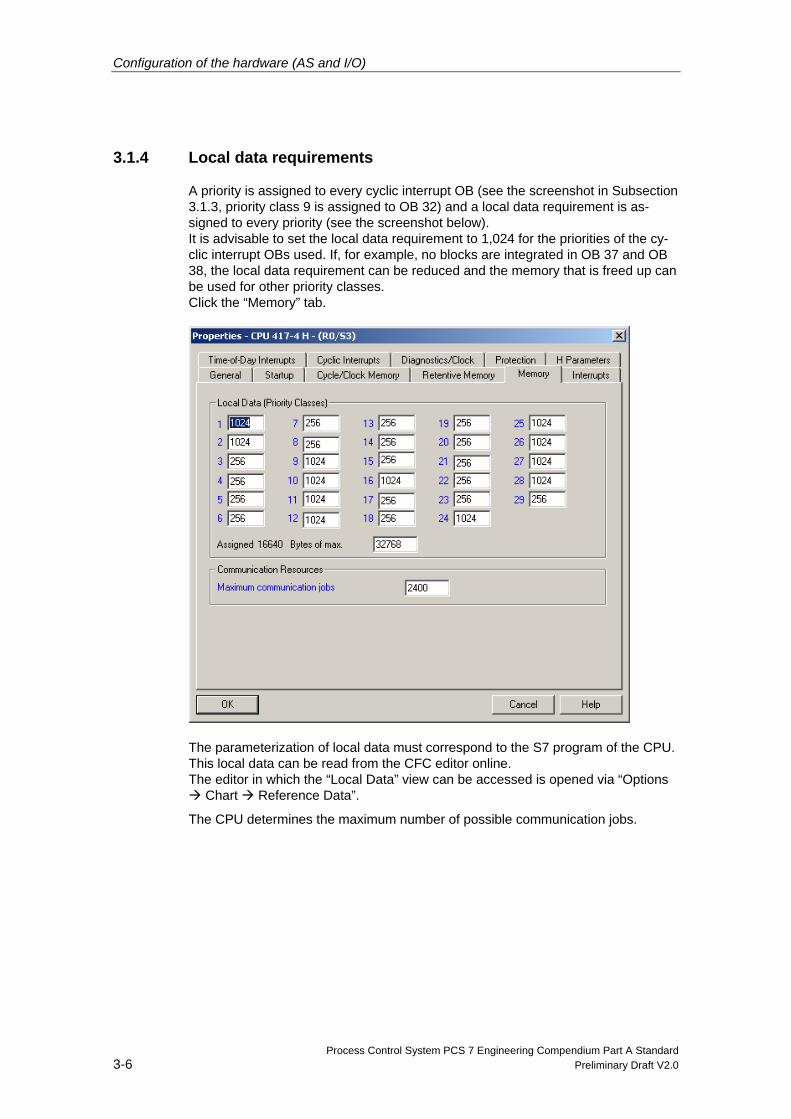
3.1.4 Local data requirements
A priority is assigned to every cyclic interrupt OB (see the screenshot in Subsection 3.1.3, priority class 9 is assigned to OB 32) and a local data requirement is as-signed to every priority (see the screenshot below). It is advisable to set the local data requirement to 1,024 for the priorities of the cy-clic interrupt OBs used. If, for example, no blocks are integrated in OB 37 and OB 38, the local data requirement can be reduced and the memory that is freed up can be used for other priority classes. Click the “Memory” tab.
The parameterization of local data must correspond to the S7 program of the CPU. This local data can be read from the CFC editor online. The editor in which the “Local Data” view can be accessed is opened via “Options
Chart Reference Data”.
The CPU determines the maximum number of possible communication jobs.
Configuration of the hardware (AS and I/O)
Process Control System PCS 7 Engineering Compendium Part A Standard Preliminary Draft V2.0 3-7
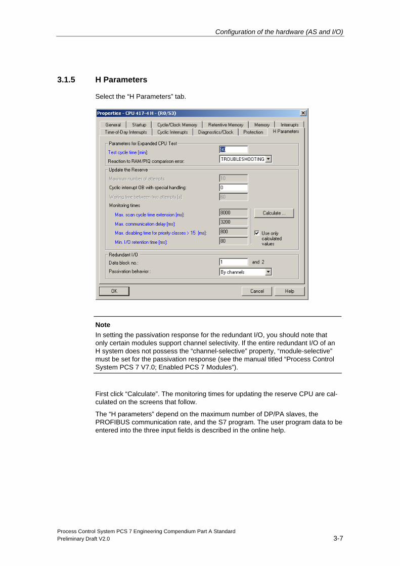
3.1.5 H Parameters
Select the “H Parameters” tab.
Note
In setting the passivation response for the redundant I/O, you should note that only certain modules support channel selectivity. If the entire redundant I/O of an H system does not possess the “channel-selective” property, “module-selective” must be set for the passivation response (see the manual titled “Process Control System PCS 7 V7.0; Enabled PCS 7 Modules”).
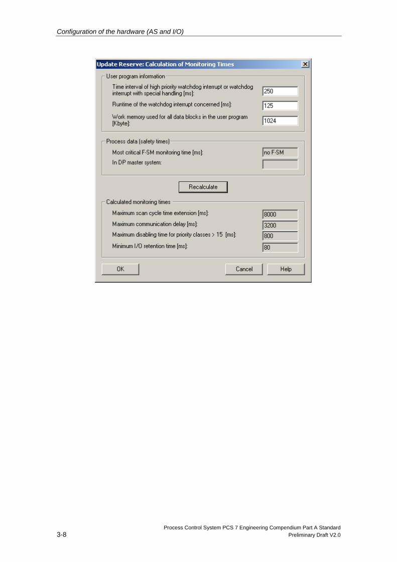
First click “Calculate”. The monitoring times for updating the reserve CPU are cal-culated on the screens that follow.
The “H parameters” depend on the maximum number of DP/PA slaves, the PROFIBUS communication rate, and the S7 program. The user program data to be entered into the three input fields is described in the online help.
Configuration of the hardware (AS and I/O)
Process Control System PCS 7 Engineering Compendium Part A Standard 3-8 Preliminary Draft V2.0
Configuration of the hardware (AS and I/O)
Process Control System PCS 7 Engineering Compendium Part A Standard Preliminary Draft V2.0 3-9
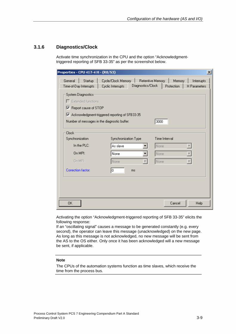
3.1.6 Diagnostics/Clock
Activate time synchronization in the CPU and the option “Acknowledgment-triggered reporting of SFB 33-35” as per the screenshot below.
Activating the option “Acknowledgment-triggered reporting of SFB 33-35” elicits the following response: If an “oscillating signal” causes a message to be generated constantly (e.g. every second), the operator can leave this message (unacknowledged) on the new page. As long as this message is not acknowledged, no new message will be sent from the AS to the OS either. Only once it has been acknowledged will a new message be sent, if applicable.
Note
The CPUs of the automation systems function as time slaves, which receive the time from the process bus.
Configuration of the hardware (AS and I/O)
Process Control System PCS 7 Engineering Compendium Part A Standard 3-10 Preliminary Draft V2.0
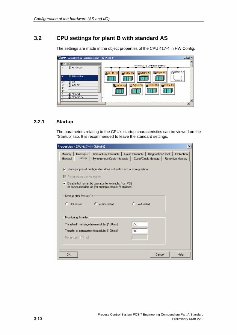
3.2 CPU settings for plant B with standard AS
The settings are made in the object properties of the CPU 417-4 in HW Config.
3.2.1 Startup
The parameters relating to the CPU’s startup characteristics can be viewed on the "Startup" tab. It is recommended to leave the standard settings.
Configuration of the hardware (AS and I/O)
Process Control System PCS 7 Engineering Compendium Part A Standard Preliminary Draft V2.0 3-11
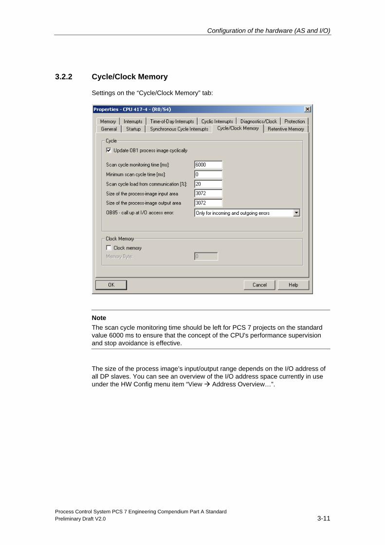
3.2.2 Cycle/Clock Memory
Settings on the “Cycle/Clock Memory” tab:
Note
The scan cycle monitoring time should be left for PCS 7 projects on the standard value 6000 ms to ensure that the concept of the CPU's performance supervision and stop avoidance is effective.
The size of the process image’s input/output range depends on the I/O address of all DP slaves. You can see an overview of the I/O address space currently in use under the HW Config menu item “View Address Overview…”.
Configuration of the hardware (AS and I/O)
Process Control System PCS 7 Engineering Compendium Part A Standard 3-12 Preliminary Draft V2.0
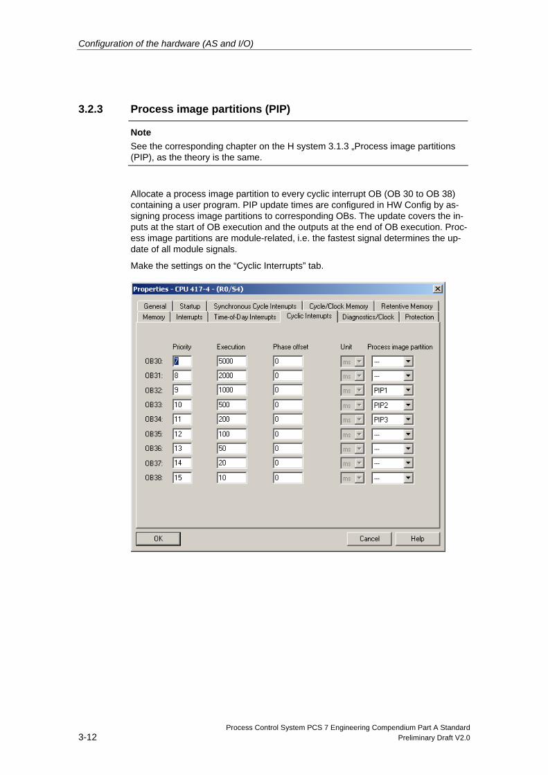
3.2.3 Process image partitions (PIP)
Note See the corresponding chapter on the H system 3.1.3 „Process image partitions (PIP), as the theory is the same.
Allocate a process image partition to every cyclic interrupt OB (OB 30 to OB 38) containing a user program. PIP update times are configured in HW Config by as-signing process image partitions to corresponding OBs. The update covers the in-puts at the start of OB execution and the outputs at the end of OB execution. Proc-ess image partitions are module-related, i.e. the fastest signal determines the up-date of all module signals.
Make the settings on the “Cyclic Interrupts” tab.
Configuration of the hardware (AS and I/O)
Process Control System PCS 7 Engineering Compendium Part A Standard Preliminary Draft V2.0 3-13
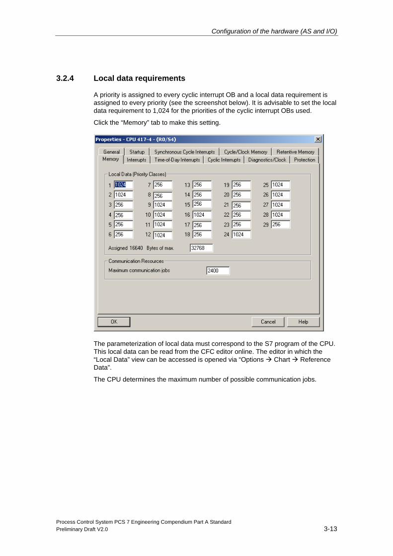
3.2.4 Local data requirements
A priority is assigned to every cyclic interrupt OB and a local data requirement is assigned to every priority (see the screenshot below). It is advisable to set the local data requirement to 1,024 for the priorities of the cyclic interrupt OBs used.
Click the “Memory” tab to make this setting.
The parameterization of local data must correspond to the S7 program of the CPU. This local data can be read from the CFC editor online. The editor in which the “Local Data” view can be accessed is opened via “Options Chart Reference Data”.
The CPU determines the maximum number of possible communication jobs.
Configuration of the hardware (AS and I/O)
Process Control System PCS 7 Engineering Compendium Part A Standard 3-14 Preliminary Draft V2.0
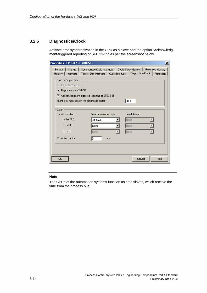
3.2.5 Diagnostics/Clock
Activate time synchronization in the CPU as a slave and the option “Acknowledg-ment-triggered reporting of SFB 33-35” as per the screenshot below.
Note
The CPUs of the automation systems function as time slaves, which receive the time from the process bus.
Configuration of the hardware (AS and I/O)
Process Control System PCS 7 Engineering Compendium Part A Standard Preliminary Draft V2.0 3-15
3.3 Configuration of Industrial Ethernet CP 443-1
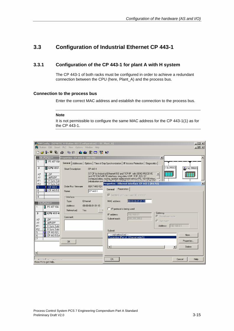
3.3.1 Configuration of the CP 443-1 for plant A with H system
The CP 443-1 of both racks must be configured in order to achieve a redundant connection between the CPU (here, Plant_A) and the process bus.
Connection to the process bus Enter the correct MAC address and establish the connection to the process bus.
Note
It is not permissible to configure the same MAC address for the CP 443-1(1) as for the CP 443-1.
Configuration of the hardware (AS and I/O)
Process Control System PCS 7 Engineering Compendium Part A Standard 3-16 Preliminary Draft V2.0
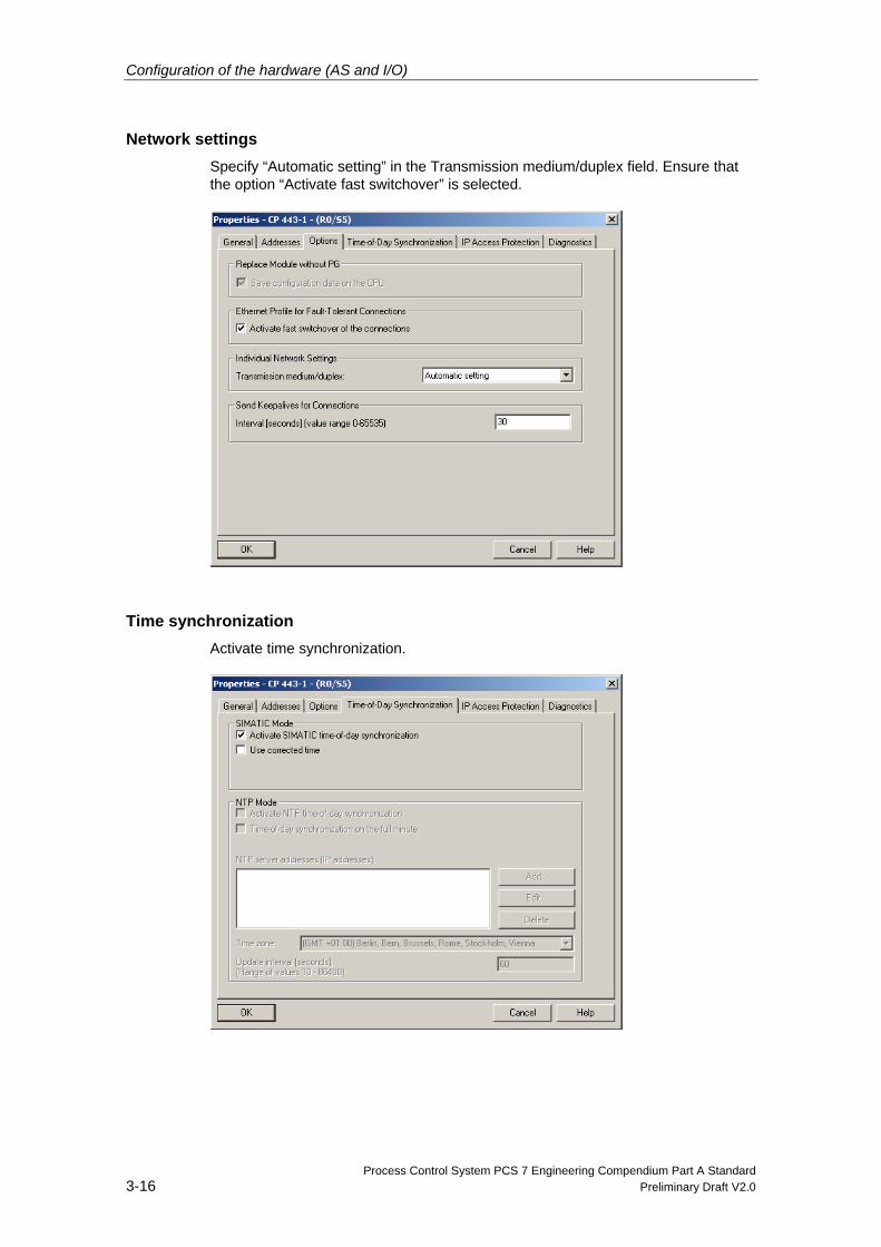
Network settings Specify “Automatic setting” in the Transmission medium/duplex field. Ensure that the option “Activate fast switchover” is selected.
Time synchronization Activate time synchronization.
Configuration of the hardware (AS and I/O)
Process Control System PCS 7 Engineering Compendium Part A Standard Preliminary Draft V2.0 3-17
Note In PCS 7 the SIMATIC process is used for time synchronization.
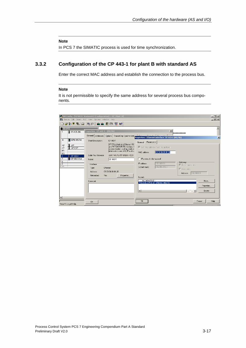
3.3.2 Configuration of the CP 443-1 for plant B with standard AS
Enter the correct MAC address and establish the connection to the process bus.
Note
It is not permissible to specify the same address for several process bus compo-nents.
Configuration of the hardware (AS and I/O)
Process Control System PCS 7 Engineering Compendium Part A Standard 3-18 Preliminary Draft V2.0
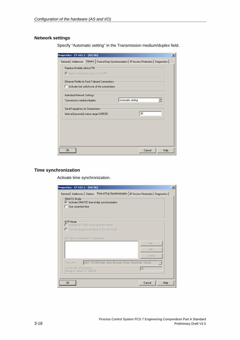
Network settings Specify “Automatic setting” in the Transmission medium/duplex field.
Time synchronization Activate time synchronization.
Configuration of the hardware (AS and I/O)
Process Control System PCS 7 Engineering Compendium Part A Standard Preliminary Draft V2.0 3-19
Note
In PCS 7 the SIMATIC process is used for time synchronization.
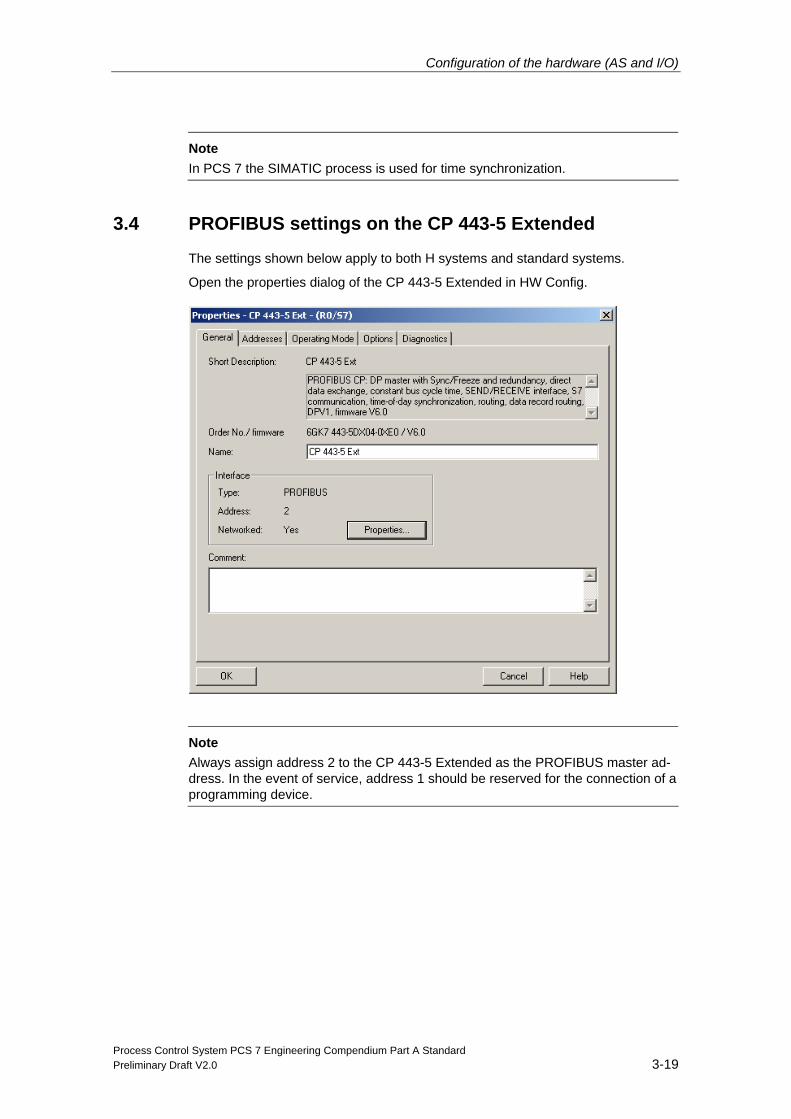
3.4 PROFIBUS settings on the CP 443-5 Extended
The settings shown below apply to both H systems and standard systems.
Open the properties dialog of the CP 443-5 Extended in HW Config.
Note
Always assign address 2 to the CP 443-5 Extended as the PROFIBUS master ad-dress. In the event of service, address 1 should be reserved for the connection of a programming device.
Configuration of the hardware (AS and I/O)
Process Control System PCS 7 Engineering Compendium Part A Standard 3-20 Preliminary Draft V2.0
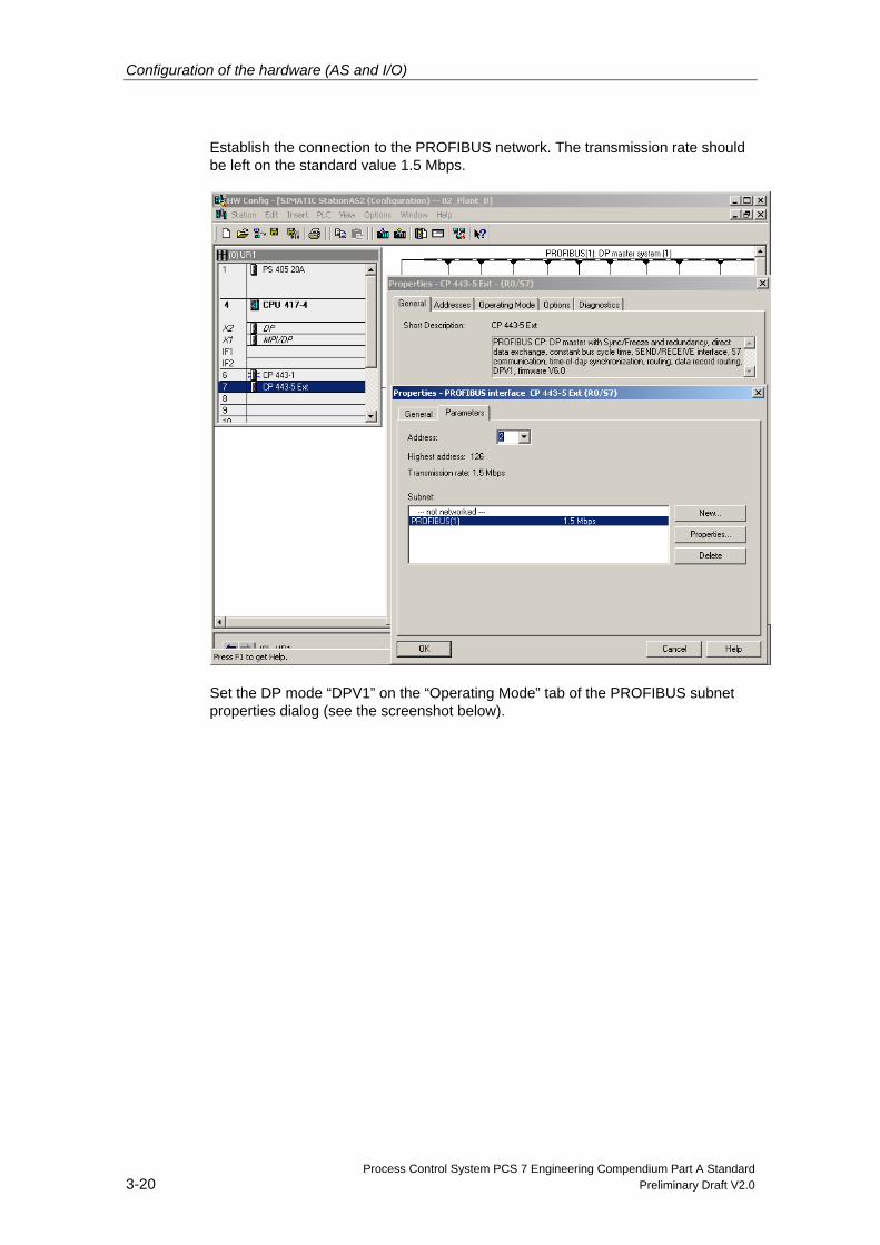
Establish the connection to the PROFIBUS network. The transmission rate should be left on the standard value 1.5 Mbps.
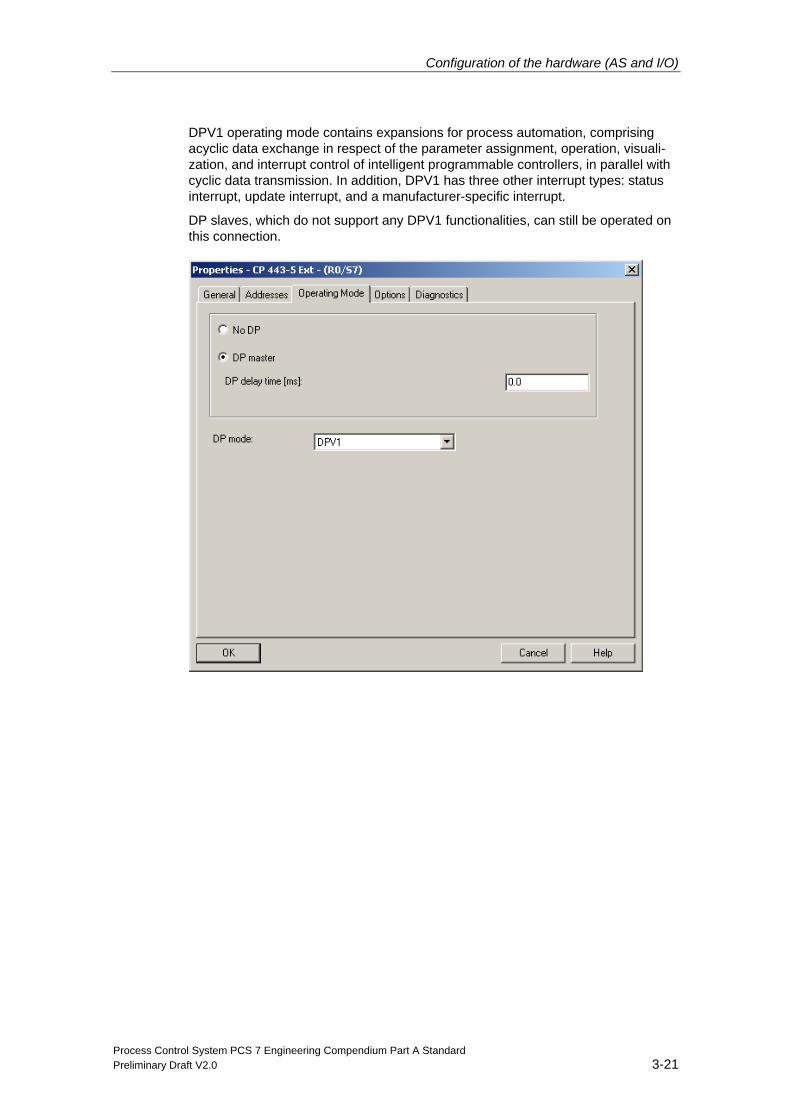
Set the DP mode “DPV1” on the “Operating Mode” tab of the PROFIBUS subnet properties dialog (see the screenshot below).
Configuration of the hardware (AS and I/O)
Process Control System PCS 7 Engineering Compendium Part A Standard Preliminary Draft V2.0 3-21
DPV1 operating mode contains expansions for process automation, comprising acyclic data exchange in respect of the parameter assignment, operation, visuali-zation, and interrupt control of intelligent programmable controllers, in parallel with cyclic data transmission. In addition, DPV1 has three other interrupt types: status interrupt, update interrupt, and a manufacturer-specific interrupt.
DP slaves, which do not support any DPV1 functionalities, can still be operated on this connection.
Configuration of the hardware (AS and I/O)
Process Control System PCS 7 Engineering Compendium Part A Standard 3-22 Preliminary Draft V2.0
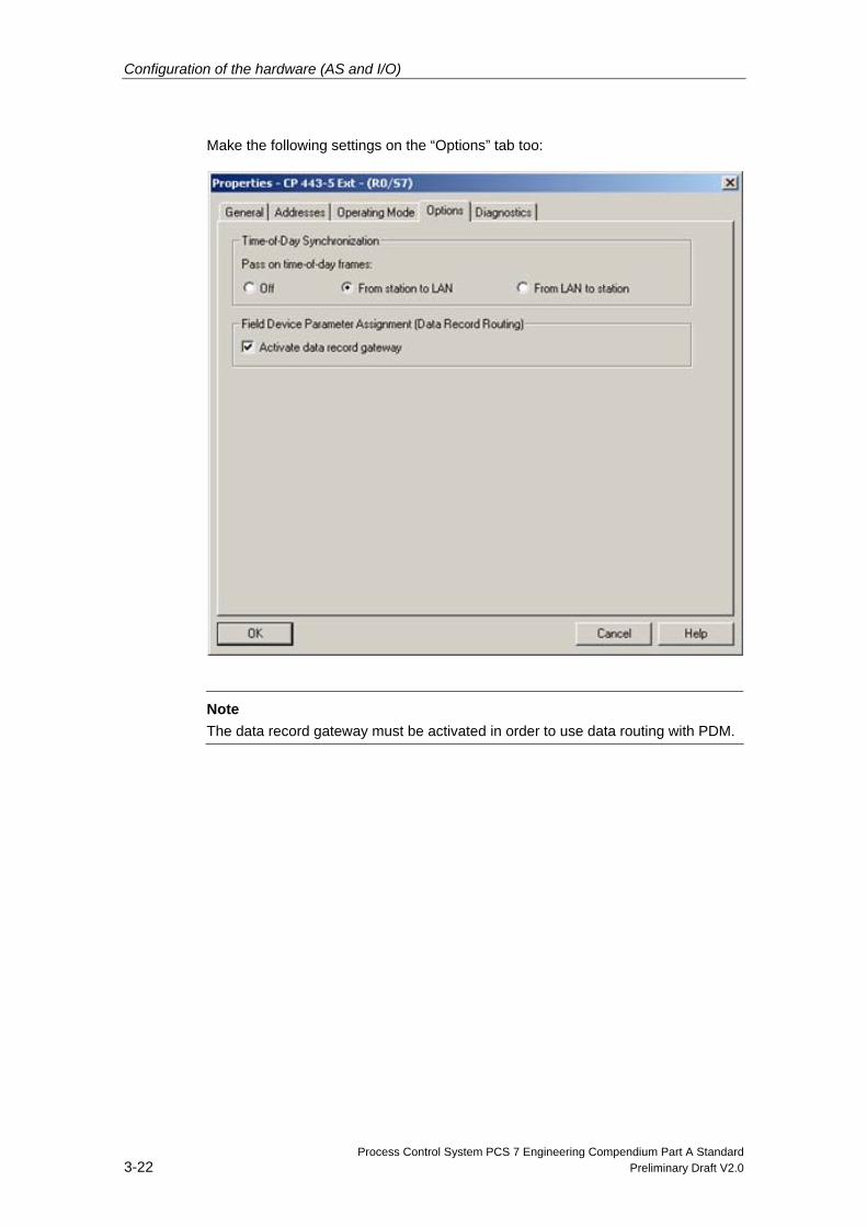
Make the following settings on the “Options” tab too:
Note
The data record gateway must be activated in order to use data routing with PDM.
Configuration of the hardware (AS and I/O)
Process Control System PCS 7 Engineering Compendium Part A Standard Preliminary Draft V2.0 3-23
3.5 Configuration of the ET 200M
3.5.1 Configuration of the ET 200M for plant A with H system
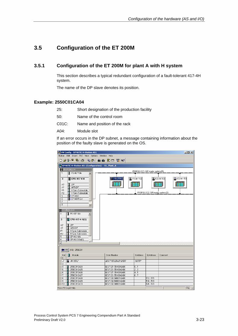
This section describes a typical redundant configuration of a fault-tolerant 417-4H system.
The name of the DP slave denotes its position.
Example: 2550C01CA04 25: Short designation of the production facility
50: Name of the control room
C01C: Name and position of the rack
A04: Module slot
If an error occurs in the DP subnet, a message containing information about the position of the faulty slave is generated on the OS.
Configuration of the hardware (AS and I/O)
Process Control System PCS 7 Engineering Compendium Part A Standard 3-24 Preliminary Draft V2.0
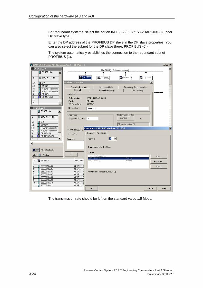
For redundant systems, select the option IM 153-2 (6ES7153-2BA01-0XB0) under DP slave type.
Enter the DP address of the PROFIBUS DP slave in the DP slave properties. You can also select the subnet for the DP slave (here, PROFIBUS (0)).
The system automatically establishes the connection to the redundant subnet PROFIBUS (1).
The transmission rate should be left on the standard value 1.5 Mbps.
Configuration of the hardware (AS and I/O)
Process Control System PCS 7 Engineering Compendium Part A Standard Preliminary Draft V2.0 3-25
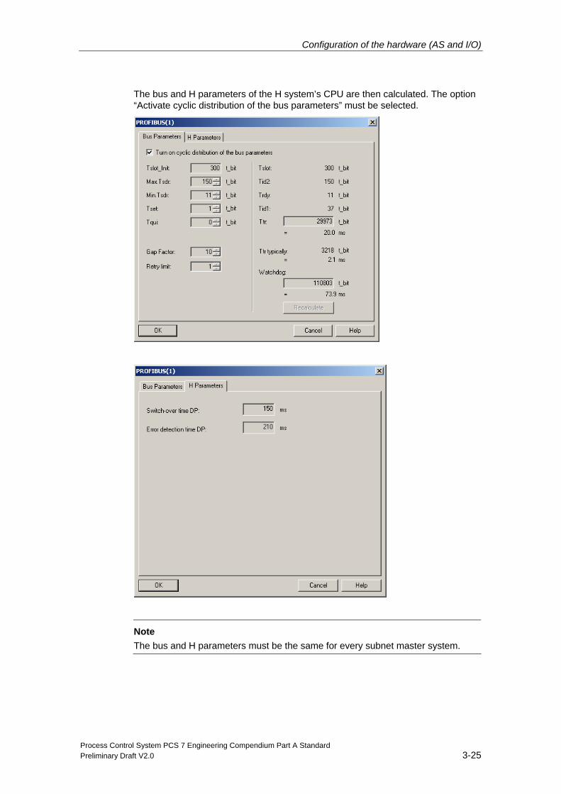
The bus and H parameters of the H system’s CPU are then calculated. The option “Activate cyclic distribution of the bus parameters” must be selected.
Note
The bus and H parameters must be the same for every subnet master system.
Configuration of the hardware (AS and I/O)
Process Control System PCS 7 Engineering Compendium Part A Standard 3-26 Preliminary Draft V2.0
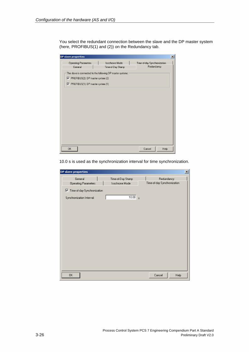
You select the redundant connection between the slave and the DP master system (here, PROFIBUS(1) and (2)) on the Redundancy tab.
10.0 s is used as the synchronization interval for time synchronization.
Configuration of the hardware (AS and I/O)
Process Control System PCS 7 Engineering Compendium Part A Standard Preliminary Draft V2.0 3-27
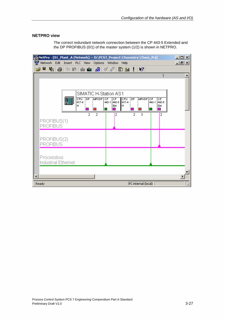
NETPRO view The correct redundant network connection between the CP 443-5 Extended and the DP PROFIBUS (0/1) of the master system (1/2) is shown in NETPRO.
Configuration of the hardware (AS and I/O)
Process Control System PCS 7 Engineering Compendium Part A Standard 3-28 Preliminary Draft V2.0
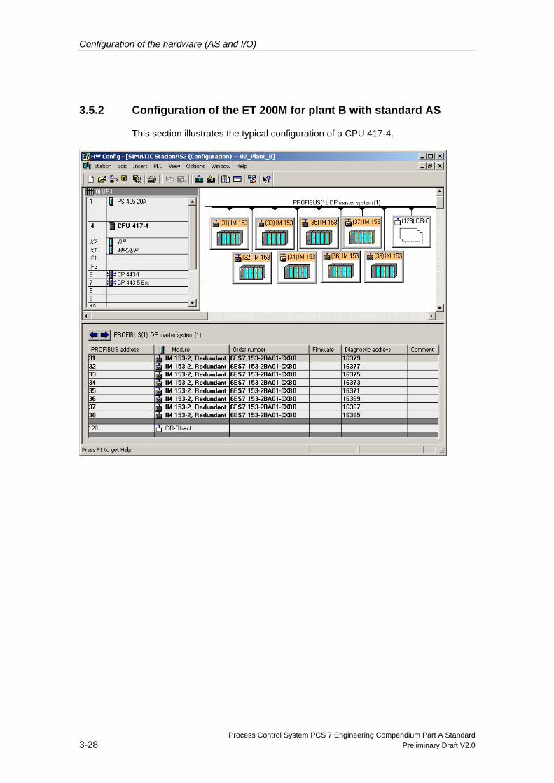
3.5.2 Configuration of the ET 200M for plant B with standard AS
This section illustrates the typical configuration of a CPU 417-4.
Configuration of the hardware (AS and I/O)
Process Control System PCS 7 Engineering Compendium Part A Standard Preliminary Draft V2.0 3-29
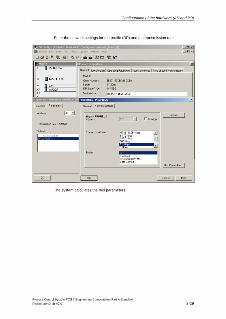
Enter the network settings for the profile (DP) and the transmission rate.
The system calculates the bus parameters.
Configuration of the hardware (AS and I/O)
Process Control System PCS 7 Engineering Compendium Part A Standard 3-30 Preliminary Draft V2.0
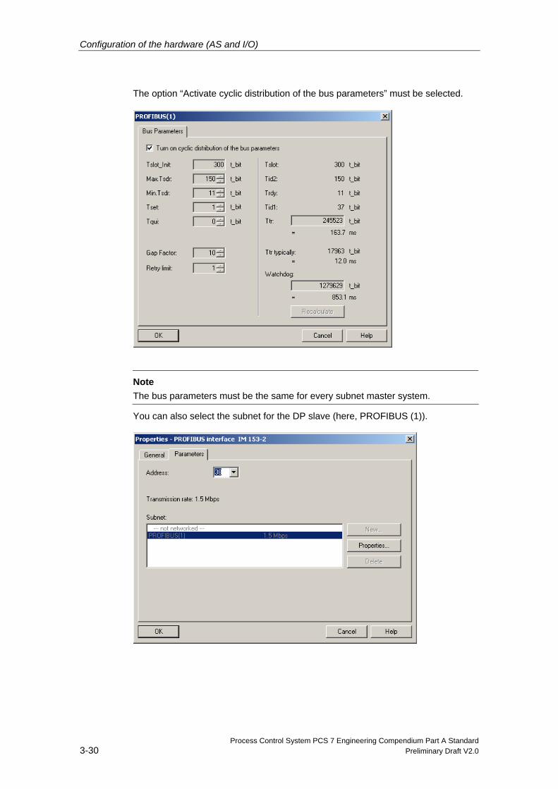
The option “Activate cyclic distribution of the bus parameters” must be selected.
Note
The bus parameters must be the same for every subnet master system.
You can also select the subnet for the DP slave (here, PROFIBUS (1)).
Configuration of the hardware (AS and I/O)
Process Control System PCS 7 Engineering Compendium Part A Standard Preliminary Draft V2.0 3-31
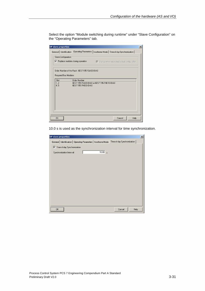
Select the option “Module switching during runtime” under “Slave Configuration” on the “Operating Parameters” tab.
10.0 s is used as the synchronization interval for time synchronization.
Configuration of the hardware (AS and I/O)
Process Control System PCS 7 Engineering Compendium Part A Standard 3-32 Preliminary Draft V2.0
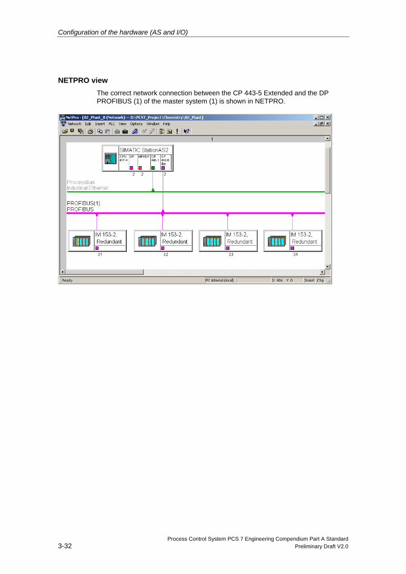
NETPRO view The correct network connection between the CP 443-5 Extended and the DP PROFIBUS (1) of the master system (1) is shown in NETPRO.
Configuration of the hardware (AS and I/O)
Process Control System PCS 7 Engineering Compendium Part A Standard Preliminary Draft V2.0 3-33
3.5.3 Symbolic names of inputs and outputs
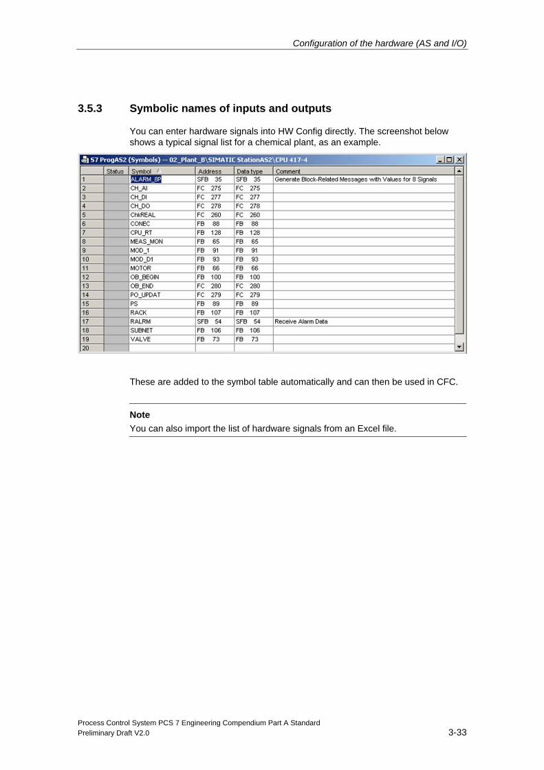
You can enter hardware signals into HW Config directly. The screenshot below shows a typical signal list for a chemical plant, as an example.
These are added to the symbol table automatically and can then be used in CFC.
Note
You can also import the list of hardware signals from an Excel file.
Configuration of the hardware (AS and I/O)
Process Control System PCS 7 Engineering Compendium Part A Standard 3-34 Preliminary Draft V2.0
3.5.4 General rules for configuring I/O modules
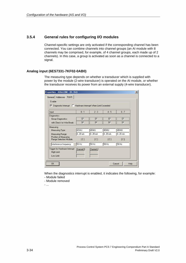
Channel-specific settings are only activated if the corresponding channel has been connected. You can combine channels into channel groups (an AI module with 8 channels may be comprised, for example, of 4 channel groups, each made up of 2 channels). In this case, a group is activated as soon as a channel is connected to a signal.
Analog input (6ES7331-7KF02-0AB0) The measuring type depends on whether a transducer which is supplied with power by the module (2-wire transducer) is operated on the AI module, or whether the transducer receives its power from an external supply (4-wire transducer).
When the diagnostics interrupt is enabled, it indicates the following, for example: - Module failed - Module removed - ...
Configuration of the hardware (AS and I/O)
Process Control System PCS 7 Engineering Compendium Part A Standard Preliminary Draft V2.0 3-35
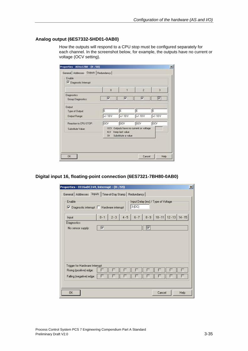
Analog output (6ES7332-5HD01-0AB0) How the outputs will respond to a CPU stop must be configured separately for each channel. In the screenshot below, for example, the outputs have no current or voltage (OCV setting).
Digital input 16, floating-point connection (6ES7321-7BH80-0AB0)
Configuration of the hardware (AS and I/O)
Process Control System PCS 7 Engineering Compendium Part A Standard 3-36 Preliminary Draft V2.0
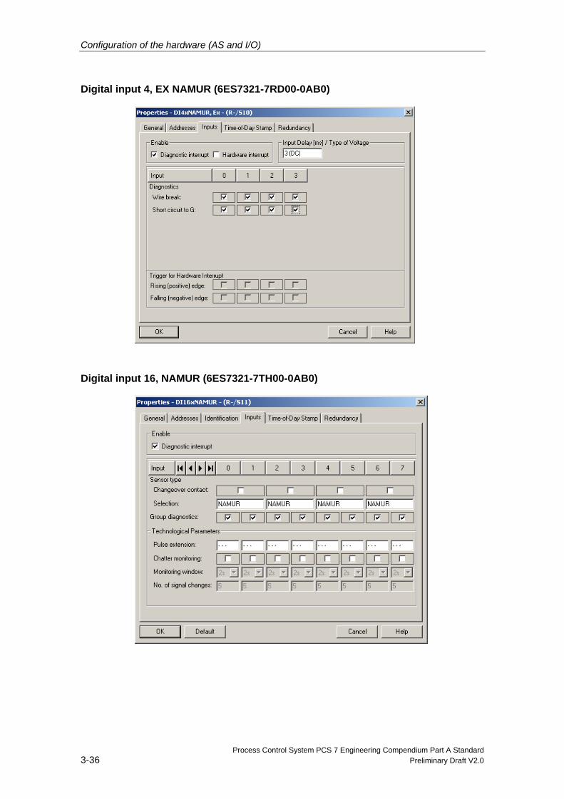
Digital input 4, EX NAMUR (6ES7321-7RD00-0AB0)
Digital input 16, NAMUR (6ES7321-7TH00-0AB0)
Configuration of the hardware (AS and I/O)
Process Control System PCS 7 Engineering Compendium Part A Standard Preliminary Draft V2.0 3-37
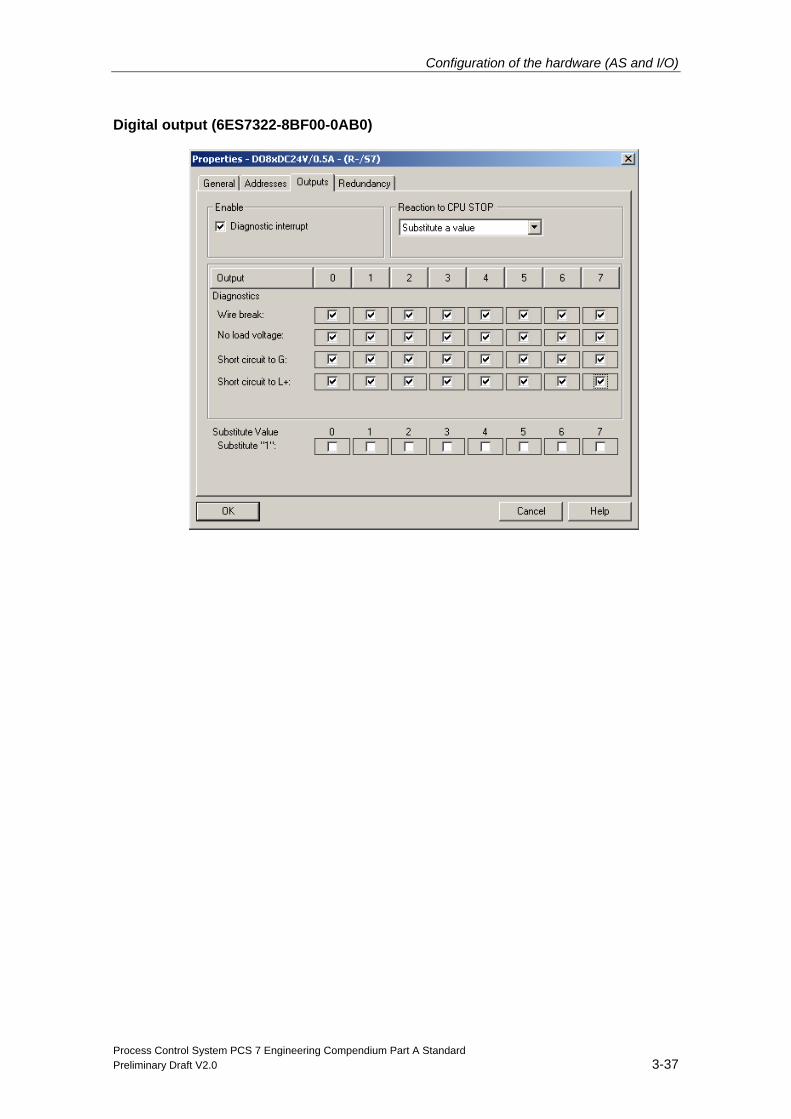
Digital output (6ES7322-8BF00-0AB0)
Configuration of the hardware (AS and I/O)
Process Control System PCS 7 Engineering Compendium Part A Standard 3-38 Preliminary Draft V2.0
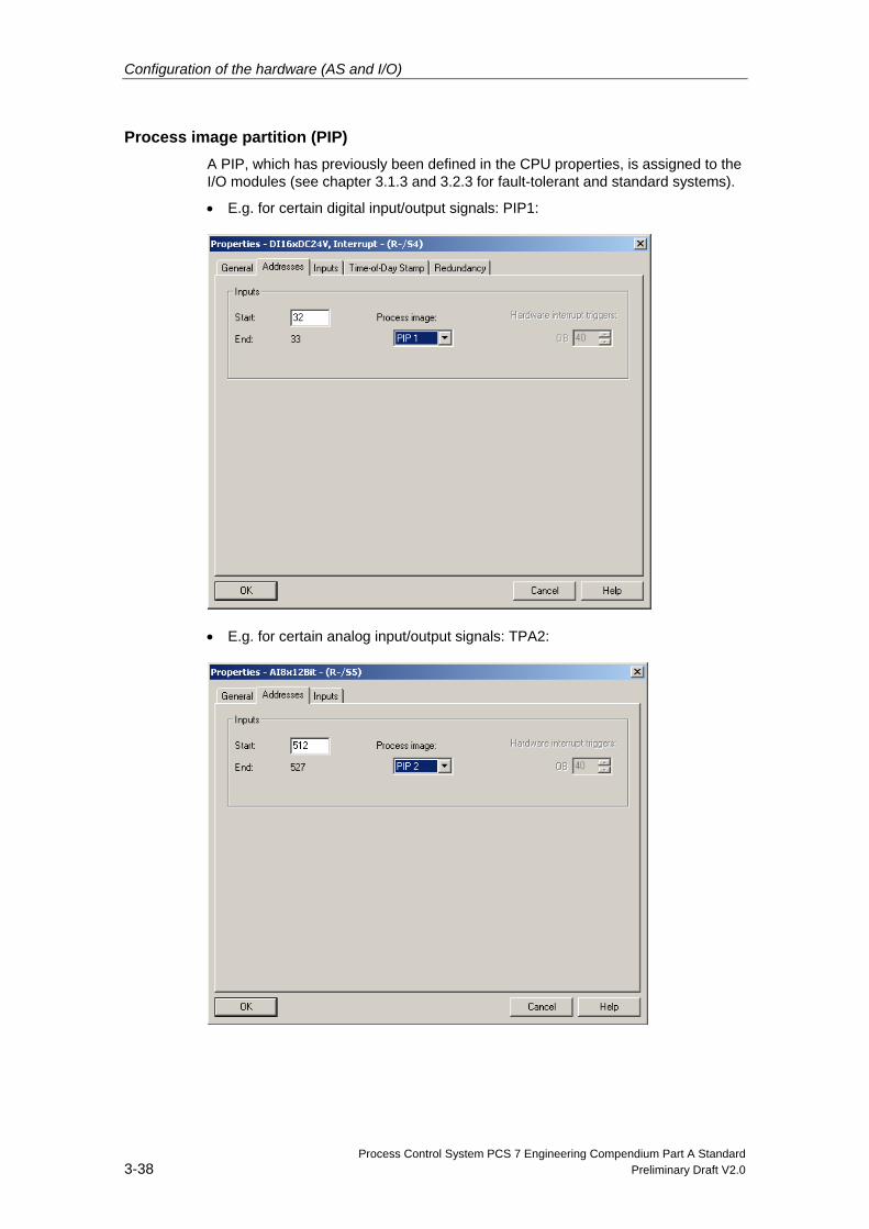
Process image partition (PIP) A PIP, which has previously been defined in the CPU properties, is assigned to the I/O modules (see chapter 3.1.3 and 3.2.3 for fault-tolerant and standard systems).
• E.g. for certain digital input/output signals: PIP1:
• E.g. for certain analog input/output signals: TPA2:
Configuration of the hardware (AS and I/O)
Process Control System PCS 7 Engineering Compendium Part A Standard Preliminary Draft V2.0 3-39
3.6 Configuration in RUN (CiR)
3.6.1 CiR in standard AS
There are some process cells which must not be shut down during operation. This may be due to the complexity of the automated process or to the high cost of re-starting. Nevertheless, it may be necessary to extend or modify the plant.
Using CiR (Configuration in RUN), it is possible to make certain changes to the configuration in the RUN operating state.
To be able to make changes to the process cell during operation, you must make provision in your original configuration for subsequently expanding the hardware of your automation system specifically for the master system used. You define suit-able CiR objects that you can later gradually replace with real objects (slaves and/or modules) in the RUN operating state. You can then download a configura-tion modified in this way to the CPU while the process is running.
You can find a more detailed description of CiR, including the possible changes during operation which require a CPU stop, in the manual titled "Making changes to the process cell during operation using CiR”.
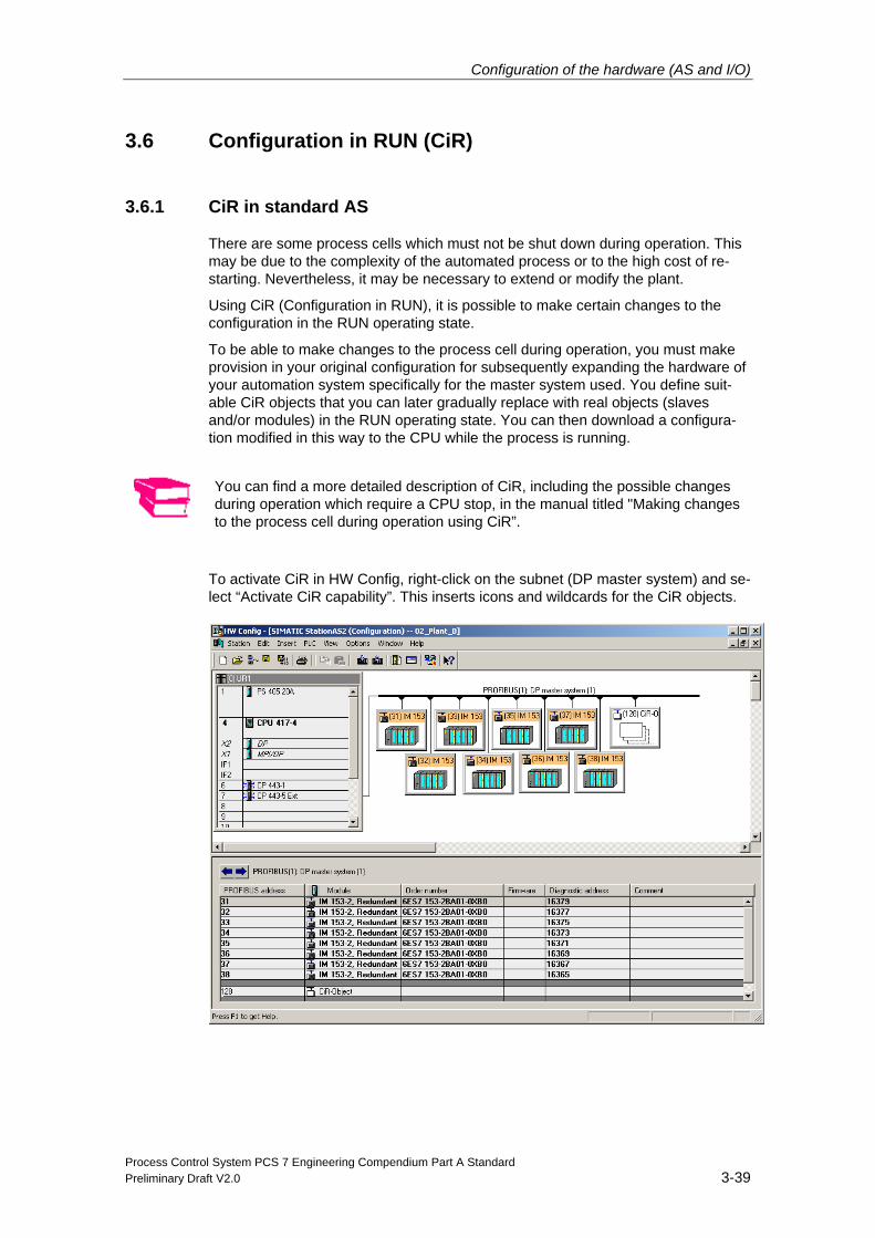
To activate CiR in HW Config, right-click on the subnet (DP master system) and se-lect “Activate CiR capability”. This inserts icons and wildcards for the CiR objects.
Configuration of the hardware (AS and I/O)
Process Control System PCS 7 Engineering Compendium Part A Standard 3-40 Preliminary Draft V2.0
Save and compile the hardware configuration and download it to the automation system in STOP mode.
3.6.2 CiR for H systems (H-CiR)
The CiR functionality for changing HW Config described above is not available in the H system, but is covered by redundant CPUs.
In addition, all parameters marked in blue in the CPU properties dialog can be modified in RUN.
You can find a more detailed description of CiR for H systems in the manual titled "Automation System S7-400H; Fault-Tolerant Systems”.
Process Control System PCS 7 Engineering Compendium Part A Standard Preliminary Draft V2.0 4-1
4 Configuration of the network connections
Once the stations have been arranged and configured, the connections between the ES/OS server and the automation systems, as well as those between the automation systems themselves, are configured and downloaded to the individual stations.
The CPs of the relevant stations must be connected to the process bus in order for these connections to be created. The ISO protocol is used for process communica-tion.
The OS clients, however, are connected to the OS servers through the terminal bus. The TCP/IP protocol is used in this network.
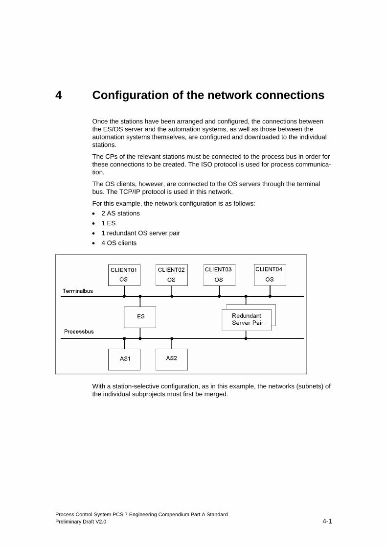
For this example, the network configuration is as follows: • 2 AS stations • 1 ES • 1 redundant OS server pair • 4 OS clients
With a station-selective configuration, as in this example, the networks (subnets) of the individual subprojects must first be merged.
Configuration of the network connections
Process Control System PCS 7 Engineering Compendium Part A Standard 4-2 Preliminary Draft V2.0
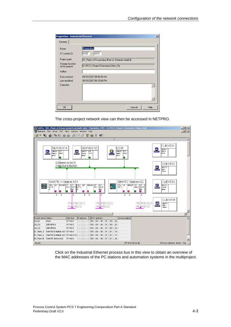
4.1 Merging networks in a multiproject
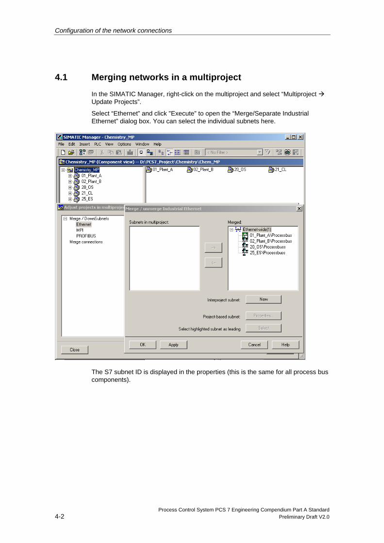
In the SIMATIC Manager, right-click on the multiproject and select “Multiproject Update Projects”.
Select “Ethernet” and click "Execute” to open the “Merge/Separate Industrial Ethernet” dialog box. You can select the individual subnets here.
The S7 subnet ID is displayed in the properties (this is the same for all process bus components).
Configuration of the network connections
Process Control System PCS 7 Engineering Compendium Part A Standard Preliminary Draft V2.0 4-3
The cross-project network view can then be accessed in NETPRO.
Click on the Industrial Ethernet process bus in this view to obtain an overview of the MAC addresses of the PC stations and automation systems in the multiproject.
Configuration of the network connections
Process Control System PCS 7 Engineering Compendium Part A Standard 4-4 Preliminary Draft V2.0
4.2 Configuration of connections
4.2.1 OS-AS connections
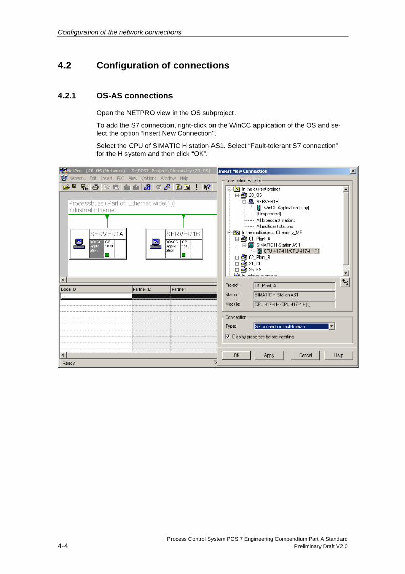
Open the NETPRO view in the OS subproject.
To add the S7 connection, right-click on the WinCC application of the OS and se-lect the option “Insert New Connection”.
Select the CPU of SIMATIC H station AS1. Select “Fault-tolerant S7 connection” for the H system and then click “OK”.
Configuration of the network connections
Process Control System PCS 7 Engineering Compendium Part A Standard Preliminary Draft V2.0 4-5
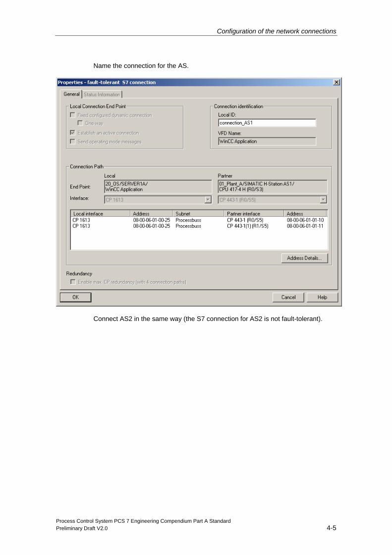
Name the connection for the AS.
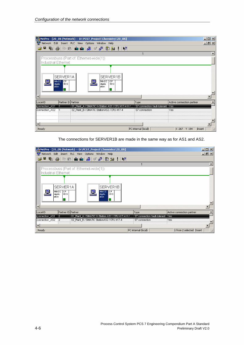
Connect AS2 in the same way (the S7 connection for AS2 is not fault-tolerant).
Configuration of the network connections
Process Control System PCS 7 Engineering Compendium Part A Standard 4-6 Preliminary Draft V2.0
The connections for SERVER1B are made in the same way as for AS1 and AS2.
Configuration of the network connections
Process Control System PCS 7 Engineering Compendium Part A Standard Preliminary Draft V2.0 4-7
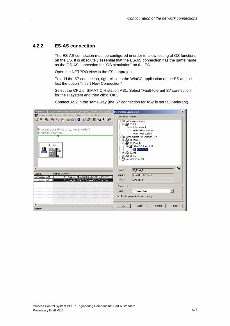
4.2.2 ES-AS connection
The ES-AS connection must be configured in order to allow testing of OS functions on the ES. It is absolutely essential that the ES-AS connection has the same name as the OS-AS connection for "OS simulation" on the ES.
Open the NETPRO view in the ES subproject.
To add the S7 connection, right-click on the WinCC application of the ES and se-lect the option “Insert New Connection”.
Select the CPU of SIMATIC H station AS1. Select “Fault-tolerant S7 connection” for the H system and then click “OK”.
Connect AS2 in the same way (the S7 connection for AS2 is not fault-tolerant).
Configuration of the network connections
Process Control System PCS 7 Engineering Compendium Part A Standard 4-8 Preliminary Draft V2.0
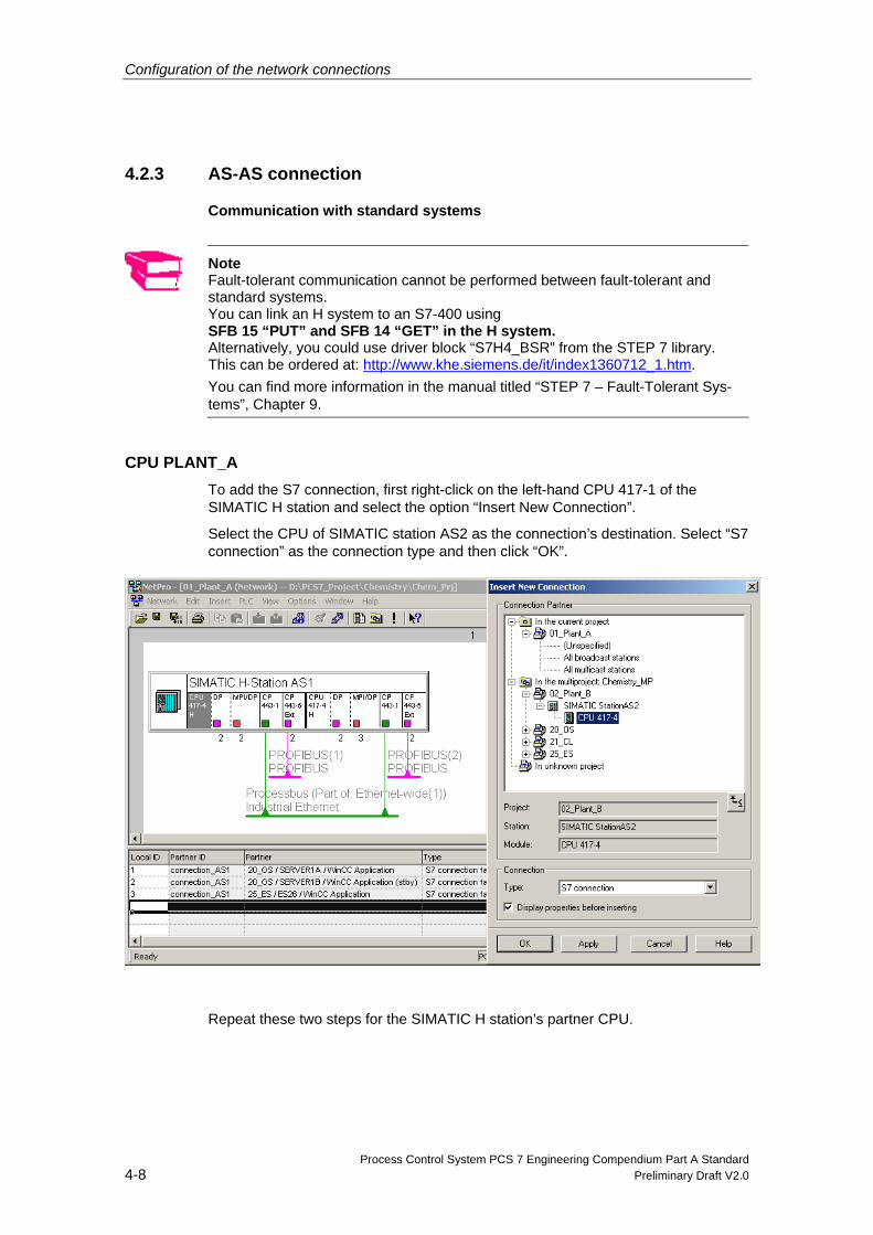
4.2.3 AS-AS connection
Communication with standard systems
Note Fault-tolerant communication cannot be performed between fault-tolerant and standard systems. You can link an H system to an S7-400 using SFB 15 “PUT” and SFB 14 “GET” in the H system. Alternatively, you could use driver block “S7H4_BSR” from the STEP 7 library. This can be ordered at: http://www.khe.siemens.de/it/index1360712_1.htm. You can find more information in the manual titled “STEP 7 – Fault-Tolerant Sys-tems”, Chapter 9.
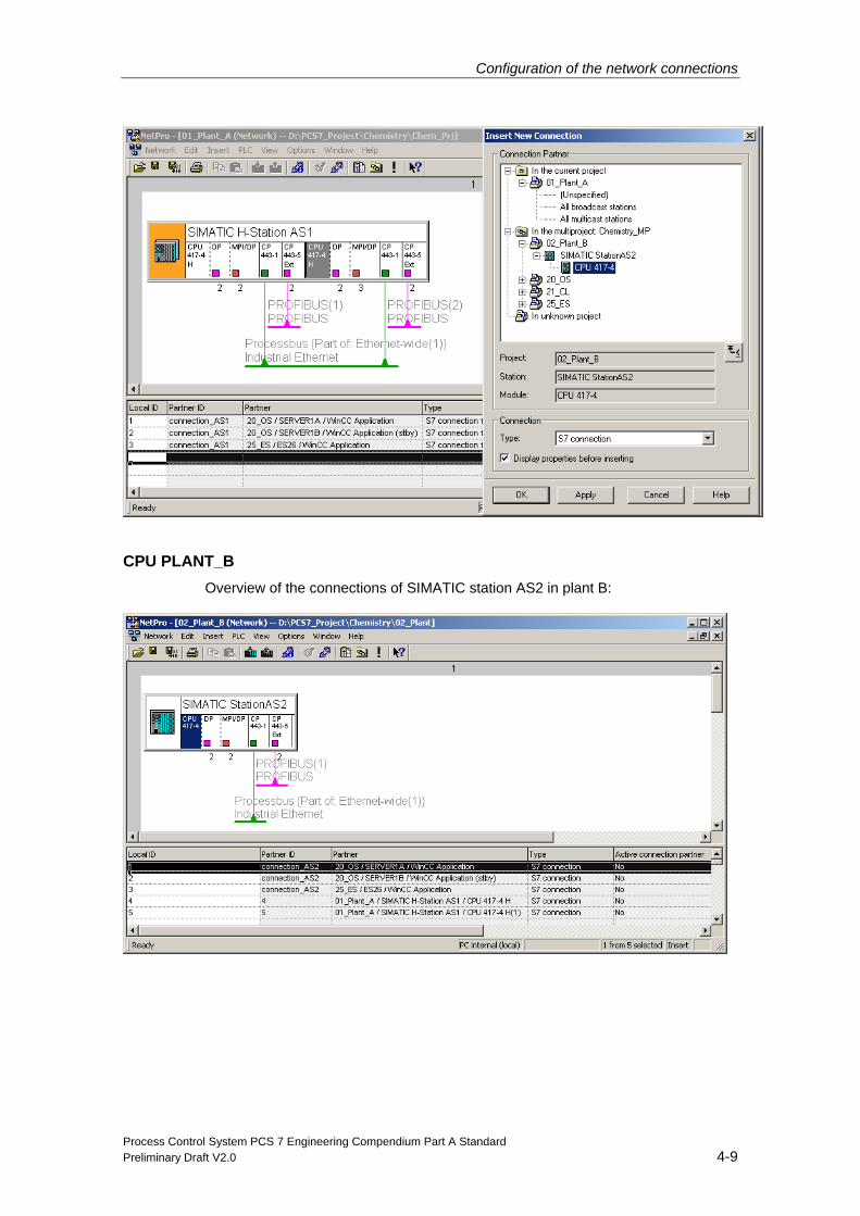
CPU PLANT_A To add the S7 connection, first right-click on the left-hand CPU 417-1 of the SIMATIC H station and select the option “Insert New Connection”.
Select the CPU of SIMATIC station AS2 as the connection’s destination. Select “S7 connection” as the connection type and then click “OK”.
Repeat these two steps for the SIMATIC H station’s partner CPU.
Configuration of the network connections
Process Control System PCS 7 Engineering Compendium Part A Standard Preliminary Draft V2.0 4-9
CPU PLANT_B Overview of the connections of SIMATIC station AS2 in plant B:
Configuration of the network connections
Process Control System PCS 7 Engineering Compendium Part A Standard 4-10 Preliminary Draft V2.0
Communication between fault-tolerant systems: “Fault-tolerant S7 connection” is used for communication between fault-tolerant systems. This type of connection is only supported by the H system (including H/2), i.e. if an AS H/2 is used in place of a standard AS, a fault-tolerant connection is configured and no other configuration work is required.
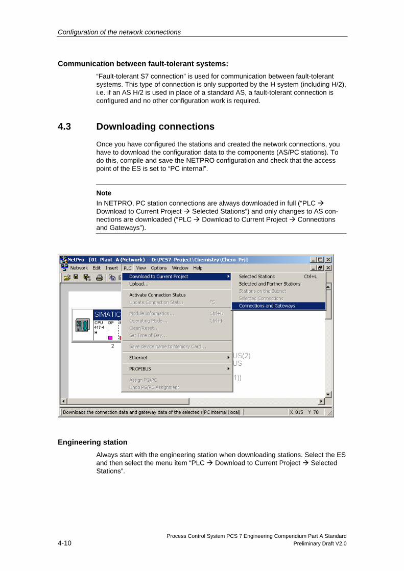
4.3 Downloading connections
Once you have configured the stations and created the network connections, you have to download the configuration data to the components (AS/PC stations). To do this, compile and save the NETPRO configuration and check that the access point of the ES is set to “PC internal”.
Note
In NETPRO, PC station connections are always downloaded in full (“PLC Download to Current Project Selected Stations”) and only changes to AS con-nections are downloaded (“PLC Download to Current Project Connections and Gateways”).
Engineering station Always start with the engineering station when downloading stations. Select the ES and then select the menu item “PLC Download to Current Project Selected Stations”.

Configuration of the network connections
Process Control System PCS 7 Engineering Compendium Part A Standard Preliminary Draft V2.0 4-11
OS server Download the configuration to SERVER1A and SERVER1B too.
AS stations Download the network configuration to the AS stations. To do this, select the menu item “PLC Download to Current Project Connections and Gateways”.

Process Control System PCS 7 Engineering Compendium Part A Standard Preliminary Draft V2.0 5-1
5 Configuring AS functions
5.1 Basics
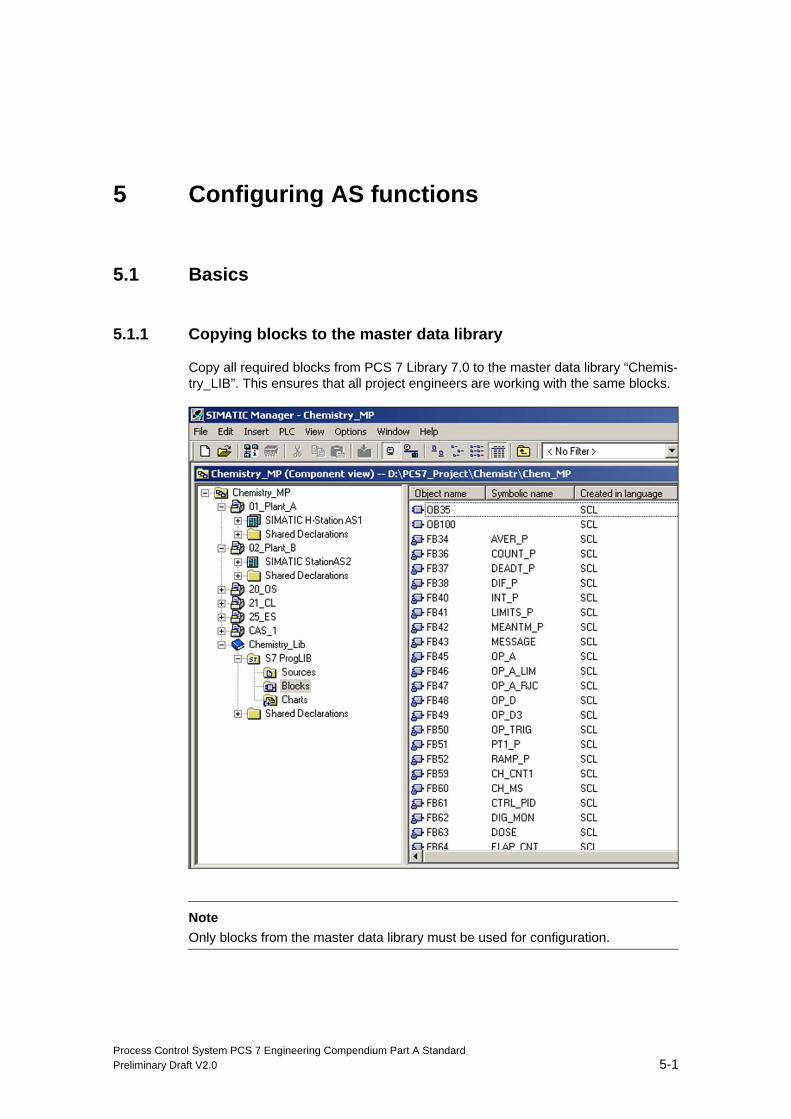
5.1.1 Copying blocks to the master data library
Copy all required blocks from PCS 7 Library 7.0 to the master data library “Chemis-try_LIB”. This ensures that all project engineers are working with the same blocks.
Note
Only blocks from the master data library must be used for configuration.
Configuring AS functions
Process Control System PCS 7 Engineering Compendium Part A Standard 5-2 Preliminary Draft V2.0
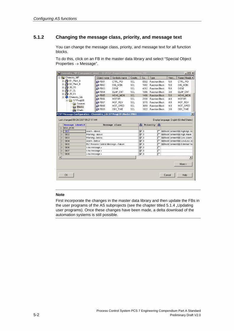
5.1.2 Changing the message class, priority, and message text
You can change the message class, priority, and message text for all function blocks.
To do this, click on an FB in the master data library and select “Special Object Properties → Message”.
Note
First incorporate the changes in the master data library and then update the FBs in the user programs of the AS subprojects (see the chapter titled 5.1.4 „Updating user programs). Once these changes have been made, a delta download of the automation systems is still possible.
Configuring AS functions
Process Control System PCS 7 Engineering Compendium Part A Standard Preliminary Draft V2.0 5-3
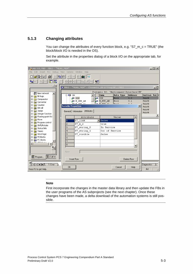
5.1.3 Changing attributes
You can change the attributes of every function block, e.g. “S7_m_c = TRUE” (the block/block I/O is needed in the OS).
Set the attribute in the properties dialog of a block I/O on the appropriate tab, for example.
Note
First incorporate the changes in the master data library and then update the FBs in the user programs of the AS subprojects (see the next chapter). Once these changes have been made, a delta download of the automation systems is still pos-sible.
Configuring AS functions
Process Control System PCS 7 Engineering Compendium Part A Standard 5-4 Preliminary Draft V2.0
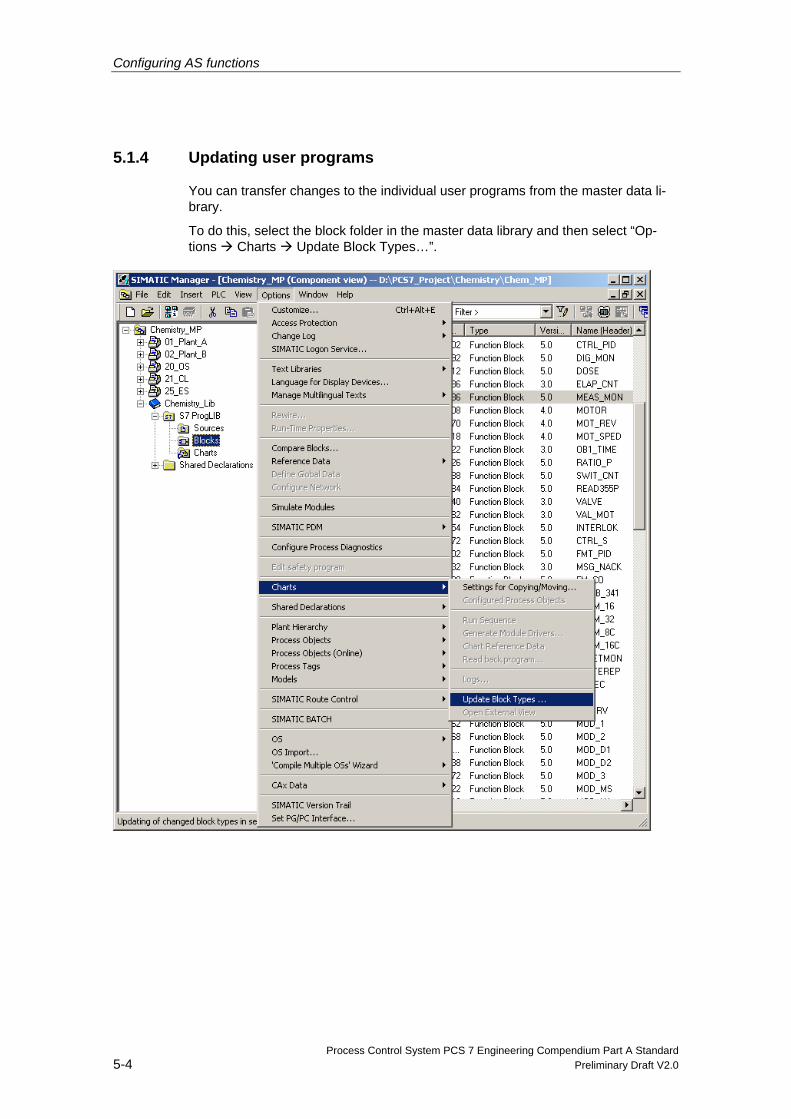
5.1.4 Updating user programs
You can transfer changes to the individual user programs from the master data li-brary.
To do this, select the block folder in the master data library and then select “Op-tions Charts Update Block Types…”.
Configuring AS functions
Process Control System PCS 7 Engineering Compendium Part A Standard Preliminary Draft V2.0 5-5
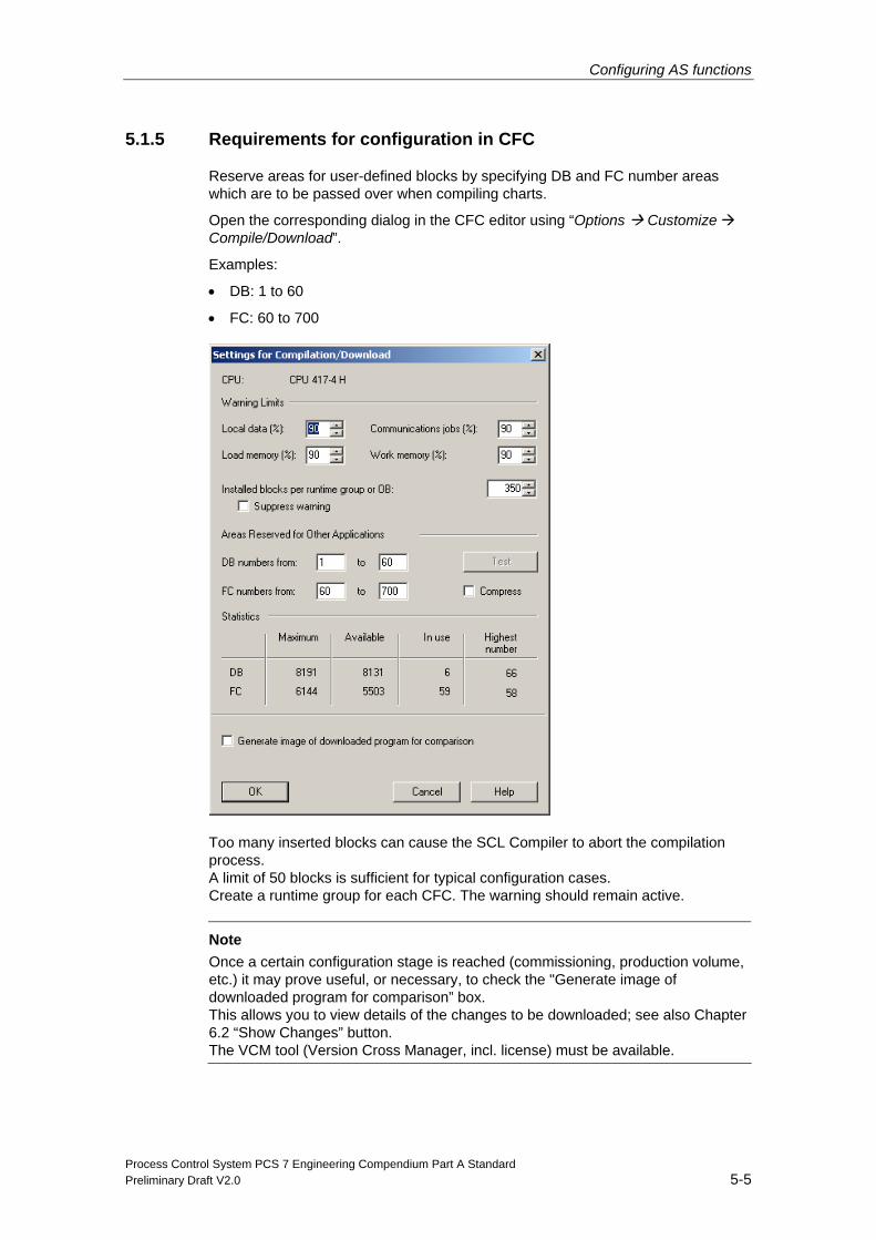
5.1.5 Requirements for configuration in CFC
Reserve areas for user-defined blocks by specifying DB and FC number areas which are to be passed over when compiling charts.
Open the corresponding dialog in the CFC editor using “Options Customize Compile/Download”.
Examples:
• DB: 1 to 60
• FC: 60 to 700
Too many inserted blocks can cause the SCL Compiler to abort the compilation process. A limit of 50 blocks is sufficient for typical configuration cases. Create a runtime group for each CFC. The warning should remain active.
Note Once a certain configuration stage is reached (commissioning, production volume, etc.) it may prove useful, or necessary, to check the "Generate image of downloaded program for comparison” box. This allows you to view details of the changes to be downloaded; see also Chapter 6.2 “Show Changes” button. The VCM tool (Version Cross Manager, incl. license) must be available.
Configuring AS functions
Process Control System PCS 7 Engineering Compendium Part A Standard 5-6 Preliminary Draft V2.0
5.1.6 Driver concept
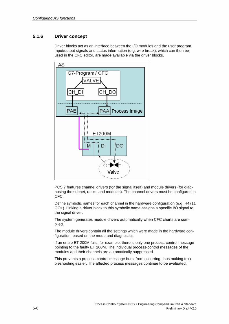
Driver blocks act as an interface between the I/O modules and the user program. Input/output signals and status information (e.g. wire break), which can then be used in the CFC editor, are made available via the driver blocks.
PCS 7 features channel drivers (for the signal itself) and module drivers (for diag-nosing the subnet, racks, and modules). The channel drivers must be configured in CFC.
Define symbolic names for each channel in the hardware configuration (e.g. H4711 GO+). Linking a driver block to this symbolic name assigns a specific I/O signal to the signal driver.
The system generates module drivers automatically when CFC charts are com-piled.
The module drivers contain all the settings which were made in the hardware con-figuration, based on the mode and diagnostics.
If an entire ET 200M fails, for example, there is only one process-control message pointing to the faulty ET 200M. The individual process-control messages of the modules and their channels are automatically suppressed.
This prevents a process-control message burst from occurring, thus making trou-bleshooting easier. The affected process messages continue to be evaluated.
Configuring AS functions
Process Control System PCS 7 Engineering Compendium Part A Standard Preliminary Draft V2.0 5-7
5.1.7 Messages from I/O peripherals
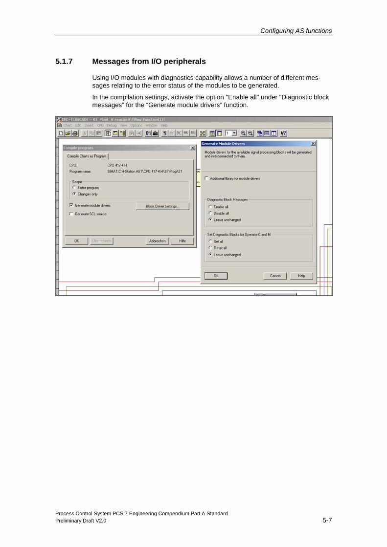
Using I/O modules with diagnostics capability allows a number of different mes-sages relating to the error status of the modules to be generated.
In the compilation settings, activate the option "Enable all" under "Diagnostic block messages” for the “Generate module drivers” function.
Configuring AS functions
Process Control System PCS 7 Engineering Compendium Part A Standard 5-8 Preliminary Draft V2.0
5.2 Creating CFC charts
5.2.1 Templates
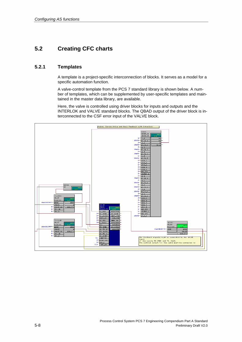
A template is a project-specific interconnection of blocks. It serves as a model for a specific automation function.
A valve-control template from the PCS 7 standard library is shown below. A num-ber of templates, which can be supplemented by user-specific templates and main-tained in the master data library, are available.
Here, the valve is controlled using driver blocks for inputs and outputs and the INTERLOK and VALVE standard blocks. The QBAD output of the driver block is in-terconnected to the CSF error input of the VALVE block.
Configuring AS functions
Process Control System PCS 7 Engineering Compendium Part A Standard Preliminary Draft V2.0 5-9
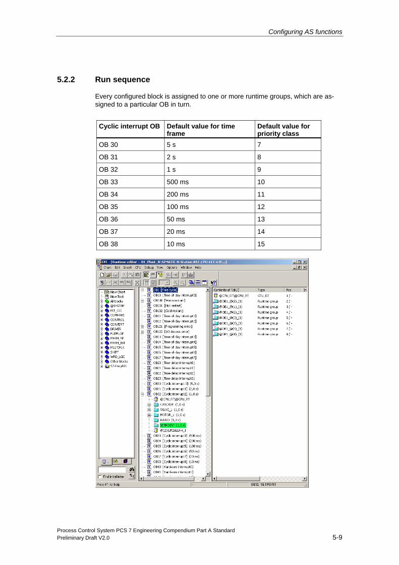
5.2.2 Run sequence
Every configured block is assigned to one or more runtime groups, which are as-signed to a particular OB in turn.
Cyclic interrupt OB Default value for time
frame Default value for priority class
OB 30 5 s 7
OB 31 2 s 8
OB 32 1 s 9
OB 33 500 ms 10
OB 34 200 ms 11
OB 35 100 ms 12
OB 36 50 ms 13
OB 37 20 ms 14
OB 38 10 ms 15
Configuring AS functions
Process Control System PCS 7 Engineering Compendium Part A Standard 5-10 Preliminary Draft V2.0
The timing of each individual block, or of the entire program, can be optimized us-ing the “Optimize run sequence” system function.
You can find more detailed information on the run sequence and how it is opti-mized in the manual titled “Process Control System PCS 7; Engineering System”.
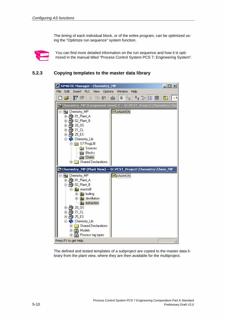
5.2.3 Copying templates to the master data library
The defined and tested templates of a subproject are copied to the master data li-brary from the plant view, where they are then available for the multiproject.
Configuring AS functions
Process Control System PCS 7 Engineering Compendium Part A Standard Preliminary Draft V2.0 5-11
5.3 Creating SFC charts
The sequential function chart, or SFC for short, is a sequential control system exe-cuted in stages which, depending on certain conditions, advances from one state to the next. A sequential control system controls functions, such as CFC charts, via mode and state changes, and processes them selectively. You create SFC charts in the SFC editor.
Block icons for SFC and SFC types are generated automatically during OS compi-lation.
You can find more information in “Process Control System PCS 7 Configuration Manual; Engineering System”.
Configuring AS functions
Process Control System PCS 7 Engineering Compendium Part A Standard 5-12 Preliminary Draft V2.0
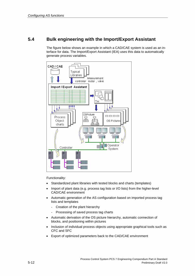
5.4 Bulk engineering with the Import/Export Assistant
The figure below shows an example in which a CAD/CAE system is used as an in-terface for data. The Import/Export Assistant (IEA) uses this data to automatically generate process variables.
Functionality: • Standardized plant libraries with tested blocks and charts (templates) • Import of plant data (e.g. process tag lists or I/O lists) from the higher-level
CAD/CAE environment • Automatic generation of the AS configuration based on imported process tag
lists and templates - Creation of the plant hierarchy - Processing of saved process tag charts
• Automatic derivation of the OS picture hierarchy, automatic connection of blocks, and positioning within pictures
• Inclusion of individual process objects using appropriate graphical tools such as CFC and SFC
• Export of optimized parameters back to the CAD/CAE environment
Configuring AS functions
Process Control System PCS 7 Engineering Compendium Part A Standard Preliminary Draft V2.0 5-13
5.4.1 Import
Import options for a process tag With the Import/Export Assistant, you can create process tags from process tag types and import the data from the import files to the process tags.
• The process tag type is copied from the master data library and to the specified target projects in the form of process tags.
• You have selected a process tag. The corresponding process tag type is se-lected.
• You have selected a project or hierarchy folder. The process tag types of the lower-level process tags are selected.
• You have selected a process tag type. This process tag type is selected.
• You have selected a master data library or one of its hierarchy folders. The lower-level process tag types are selected.
Import options using a model With the Import/Export Assistant, you can create replicas of models and import the data from the import files to the replicas.
• If you have selected a hierarchy folder that is a model, only this model is se-lected for import.
• If you have selected a higher-level hierarchy folder (or the project node) with lower-level models, all models are selected for import.
5.4.2 Export
You can use the Import/Export Assistant to export process tag data. All accessible projects in the multiproject are taken into account.
If you have selected a higher-level hierarchy folder (or the project node) with lower-level process tags, all the lower-level process tags are selected for export and the data is exported. Each process tag type is assigned an export file, each process tag of the process tag type is assigned a row in the corresponding export file.
You can use the Import/Export Assistant to export the data of the model replicas.
Configuring AS functions
Process Control System PCS 7 Engineering Compendium Part A Standard 5-14 Preliminary Draft V2.0
Export options • If you have selected a hierarchy folder that represents a model, only this model
is selected for export.
• If you have selected a higher-level hierarchy folder (or the project node) with lower-level models, all the lower-level models are selected for export and the replica data is exported.
Export dialog Select the required hierarchy folder, project node, the process tag library (hierarchy folder in the project library), or the process tag type.
Select the menu command “Options Process Tags Export” or “Options Models Export”.
Modify the export settings and click “Finish” to start the export procedure.
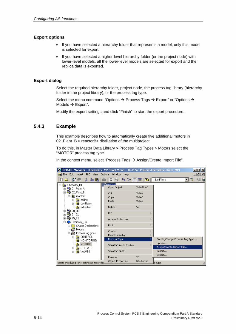
5.4.3 Example
This example describes how to automatically create five additional motors in 02_Plant_B > reactorB> distillation of the multiproject.
To do this, in Master Data Library > Process Tag Types > Motors select the “MOTOR” process tag type.
In the context menu, select “Process Tags Assign/Create Import File”.
Configuring AS functions
Process Control System PCS 7 Engineering Compendium Part A Standard Preliminary Draft V2.0 5-15
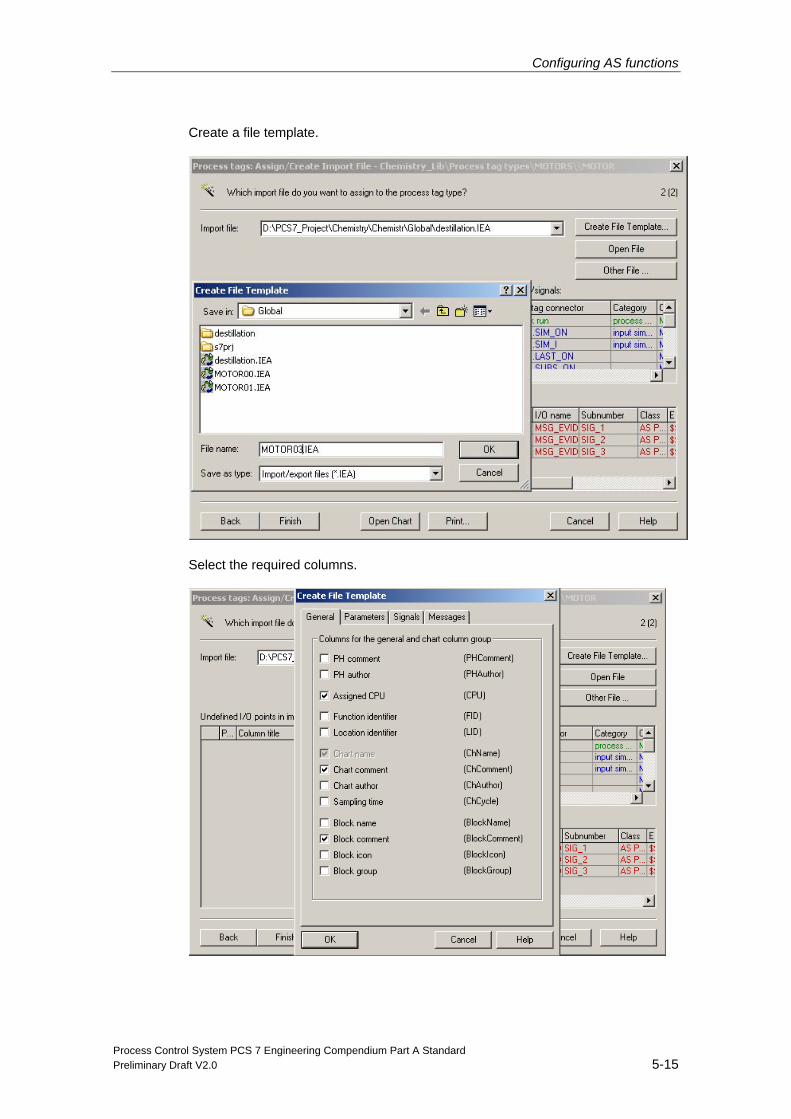
Create a file template.
Select the required columns.
Configuring AS functions
Process Control System PCS 7 Engineering Compendium Part A Standard 5-16 Preliminary Draft V2.0
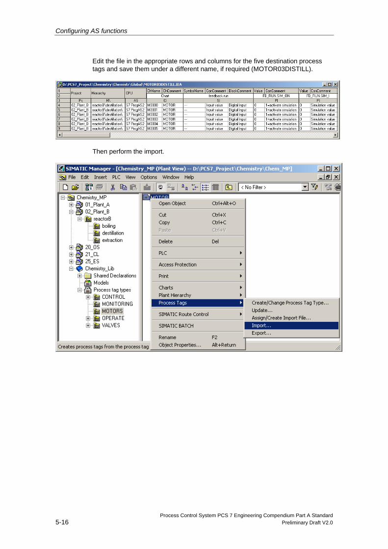
Edit the file in the appropriate rows and columns for the five destination process tags and save them under a different name, if required (MOTOR03DISTILL).
Then perform the import.
Configuring AS functions
Process Control System PCS 7 Engineering Compendium Part A Standard Preliminary Draft V2.0 5-17
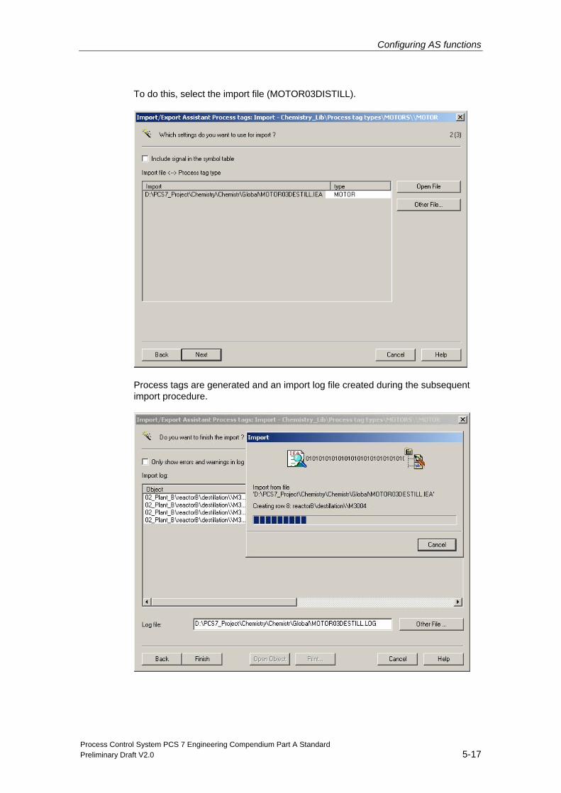
To do this, select the import file (MOTOR03DISTILL).
Process tags are generated and an import log file created during the subsequent import procedure.
Configuring AS functions
Process Control System PCS 7 Engineering Compendium Part A Standard 5-18 Preliminary Draft V2.0
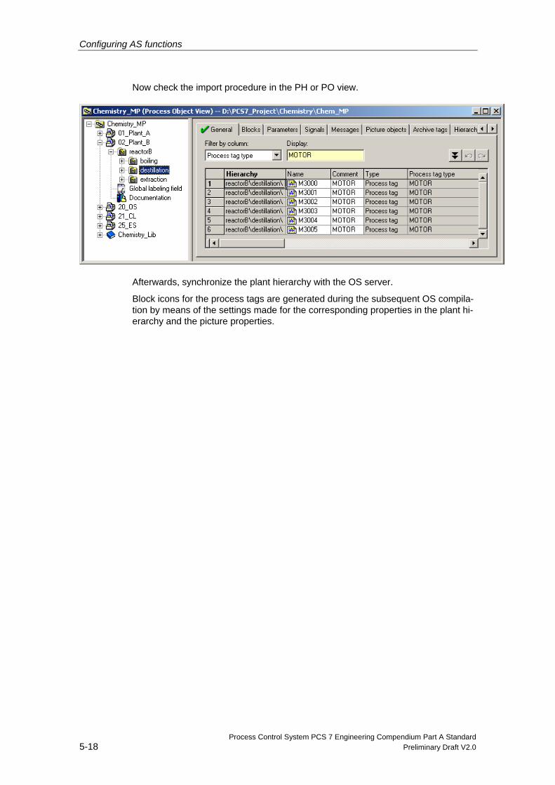
Now check the import procedure in the PH or PO view.
Afterwards, synchronize the plant hierarchy with the OS server.
Block icons for the process tags are generated during the subsequent OS compila-tion by means of the settings made for the corresponding properties in the plant hi-erarchy and the picture properties.
Configuring AS functions
Process Control System PCS 7 Engineering Compendium Part A Standard Preliminary Draft V2.0 5-19
5.5 Bulk engineering in the process object view In the process object view, all the data of the basic control can be displayed in a process-control-oriented view throughout the project. This means that a multipro-ject encompasses the data of all the projects contained in it.
5.5.1 Functionality
The process object view window contains 10 tabs for the various aspects of the ob-jects:
General This tab displays all the lower-level ES objects (process tags, CFCs, SFCs, pic-tures, reports, or additional documents) and their general information for the plant unit currently selected in the left-hand window.
Blocks This tab displays the properties of all CFC chart blocks contained in the selected object of the hierarchy window. SFC instances are also identified as blocks here.
Parameters This tab shows the I/O points of all the process tags and CFCs displayed on the "General" tab that were selected explicitly for editing in the process object view (S7_edit = para).
Signals This tab shows the I/O points of all the process tags and CFCs displayed on the "General" tab that were selected explicitly for editing in the process object view (S7_edit = signal).
Messages This tab shows the messages corresponding to all the process tags and CFC charts displayed on the "General" tab.
Picture Objects This tab shows the picture interconnections that exist in the PCS 7 OS, if applica-ble, for all the process tags and CFCs displayed on the "General" tab.
Configuring AS functions
Process Control System PCS 7 Engineering Compendium Part A Standard 5-20 Preliminary Draft V2.0
Archive Tags This tab shows any interconnected OS archive tags, along with their attributes, for all the process tags, CFC charts, and SFC charts displayed on the "General" tab. Each archive tag is visualized in a separate row.
Hierarchy Folder This tab displays the hierarchy folders of the plant hierarchy contained in the se-lected object of the hierarchy window. One row is displayed for each available hi-erarchy folder.
Equipment Properties These equipment properties are instances created by equipment property types configured in the shared declarations. A row is displayed for each existing equip-ment property. If changes are made to a type, the attributes that cannot be edited here are transferred to the instance.
Shared Declarations On this tab you can edit the attributes of the types of enumerations, units, and equipment properties contained in the project.
Cross probes to CFC, SFC, HW Config, and PCS 7 OS enable you to edit aspects which cannot be edited in the table too (e.g. module parameter assignments, pic-ture contents, etc.).
5.5.2 Example
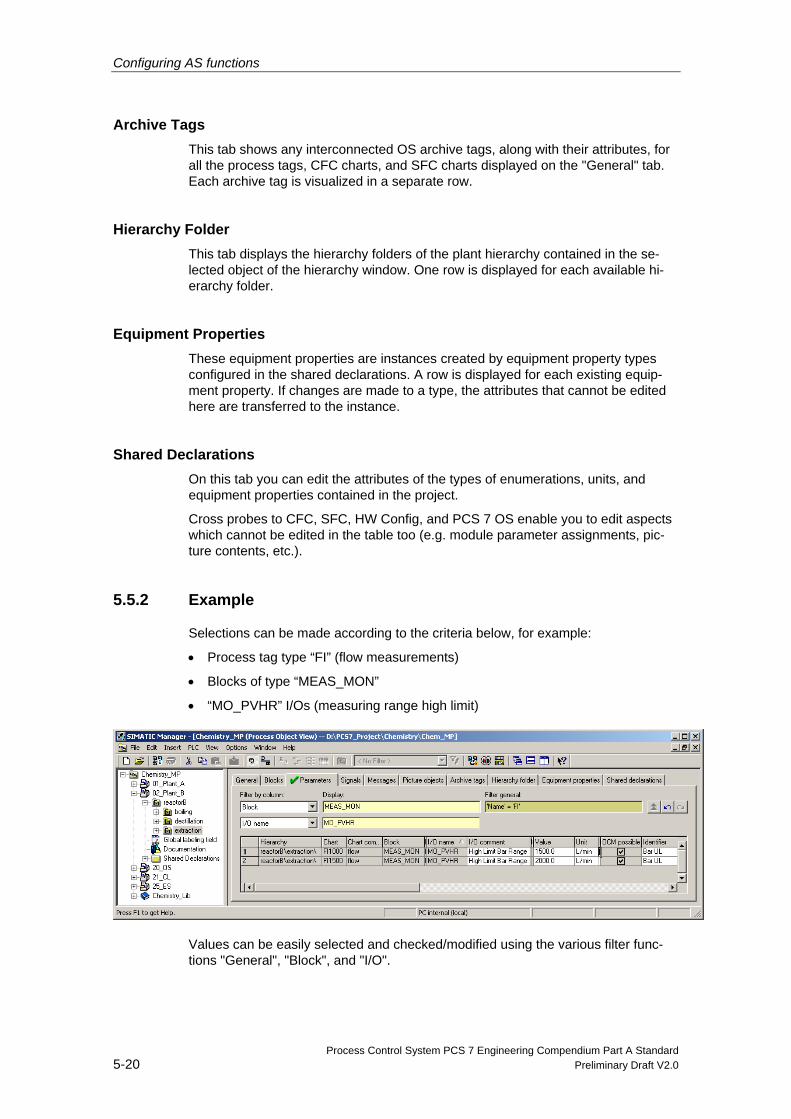
Selections can be made according to the criteria below, for example:
• Process tag type “FI” (flow measurements)
• Blocks of type “MEAS_MON”
• “MO_PVHR” I/Os (measuring range high limit)
Values can be easily selected and checked/modified using the various filter func-tions "General", "Block", and "I/O".
Configuring AS functions
Process Control System PCS 7 Engineering Compendium Part A Standard Preliminary Draft V2.0 5-21
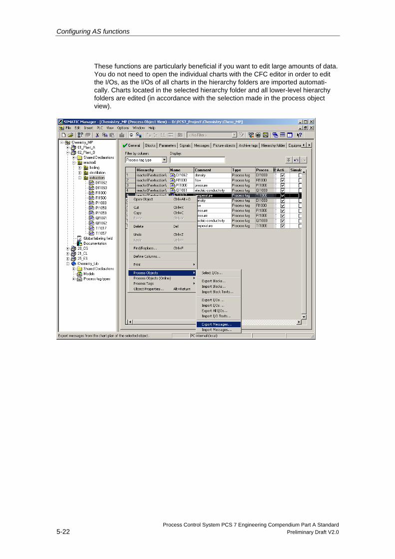
5.5.3 Exporting and importing I/Os and messages
In exporting and importing attributes, the following can be done to parameter, sig-nal, and message information:
• export them to a file,
• edit them using standard applications (EXCEL, ACCESS),
Open the import/export file using EXCEL, rather than by double-clicking on the CSV file.
- First start the EXCEL program.
- Use the menu command “File Open...” to select the correct file. The con-tent is now arranged by column according to the column headers.
• re-import them.
Configuring AS functions
Process Control System PCS 7 Engineering Compendium Part A Standard 5-22 Preliminary Draft V2.0
These functions are particularly beneficial if you want to edit large amounts of data. You do not need to open the individual charts with the CFC editor in order to edit the I/Os, as the I/Os of all charts in the hierarchy folders are imported automati-cally. Charts located in the selected hierarchy folder and all lower-level hierarchy folders are edited (in accordance with the selection made in the process object view).
Process Control System PCS 7 Engineering Compendium Part A Standard Preliminary Draft V2.0 6-1
6 Compiling and downloading
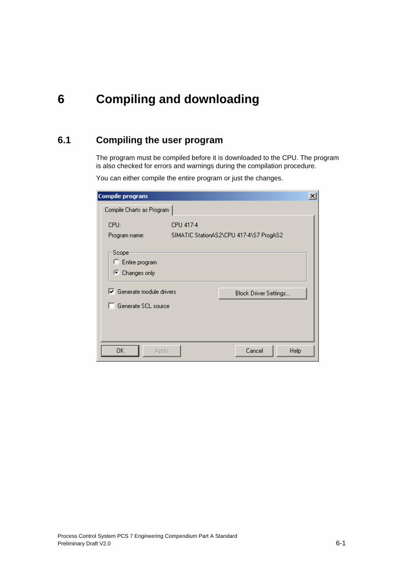
6.1 Compiling the user program
The program must be compiled before it is downloaded to the CPU. The program is also checked for errors and warnings during the compilation procedure.
You can either compile the entire program or just the changes.
Compiling and downloading
Process Control System PCS 7 Engineering Compendium Part A Standard 6-2 Preliminary Draft V2.0
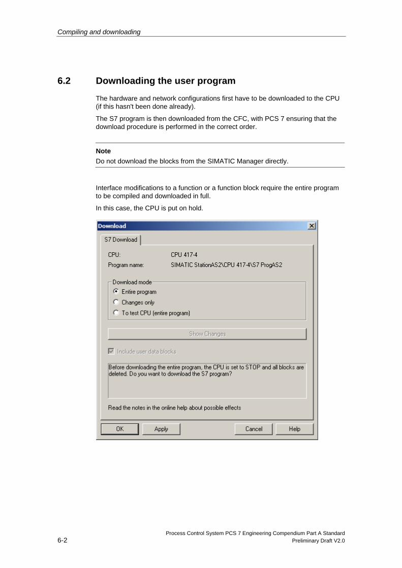
6.2 Downloading the user program
The hardware and network configurations first have to be downloaded to the CPU (if this hasn't been done already).
The S7 program is then downloaded from the CFC, with PCS 7 ensuring that the download procedure is performed in the correct order.
Note
Do not download the blocks from the SIMATIC Manager directly.
Interface modifications to a function or a function block require the entire program to be compiled and downloaded in full.
In this case, the CPU is put on hold.
Compiling and downloading
Process Control System PCS 7 Engineering Compendium Part A Standard Preliminary Draft V2.0 6-3
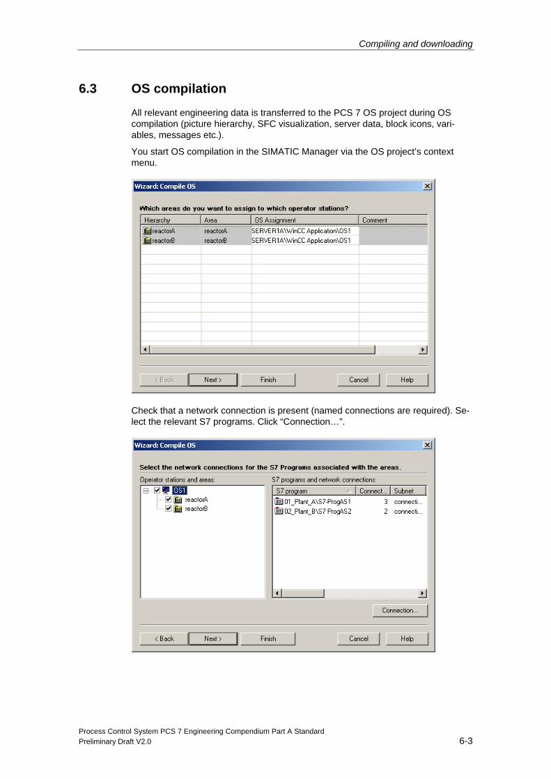
6.3 OS compilation
All relevant engineering data is transferred to the PCS 7 OS project during OS compilation (picture hierarchy, SFC visualization, server data, block icons, vari-ables, messages etc.).
You start OS compilation in the SIMATIC Manager via the OS project’s context menu.
Check that a network connection is present (named connections are required). Se-lect the relevant S7 programs. Click “Connection…”.
Compiling and downloading
Process Control System PCS 7 Engineering Compendium Part A Standard 6-4 Preliminary Draft V2.0
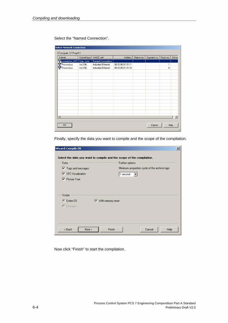
Select the “Named Connection”.
Finally, specify the data you want to compile and the scope of the compilation.
Now click “Finish” to start the compilation.
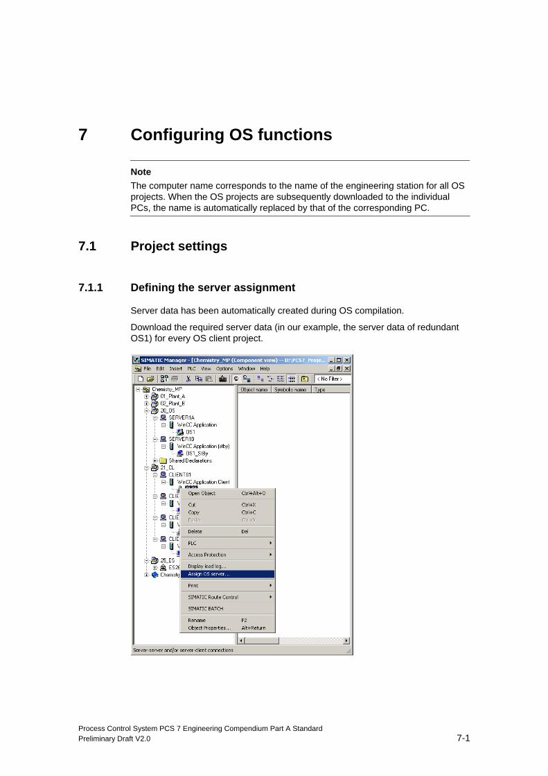
Process Control System PCS 7 Engineering Compendium Part A Standard Preliminary Draft V2.0 7-1
7 Configuring OS functions
Note The computer name corresponds to the name of the engineering station for all OS projects. When the OS projects are subsequently downloaded to the individual PCs, the name is automatically replaced by that of the corresponding PC.
7.1 Project settings
7.1.1 Defining the server assignment
Server data has been automatically created during OS compilation.
Download the required server data (in our example, the server data of redundant OS1) for every OS client project.
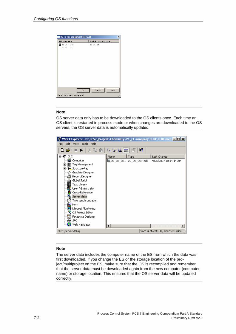
Configuring OS functions
Process Control System PCS 7 Engineering Compendium Part A Standard 7-2 Preliminary Draft V2.0
Note
OS server data only has to be downloaded to the OS clients once. Each time an OS client is restarted in process mode or when changes are downloaded to the OS servers, the OS server data is automatically updated.
Note
The server data includes the computer name of the ES from which the data was first downloaded. If you change the ES or the storage location of the pro-ject/multiproject on the ES, make sure that the OS is recompiled and remember that the server data must be downloaded again from the new computer (computer name) or storage location. This ensures that the OS server data will be updated correctly.
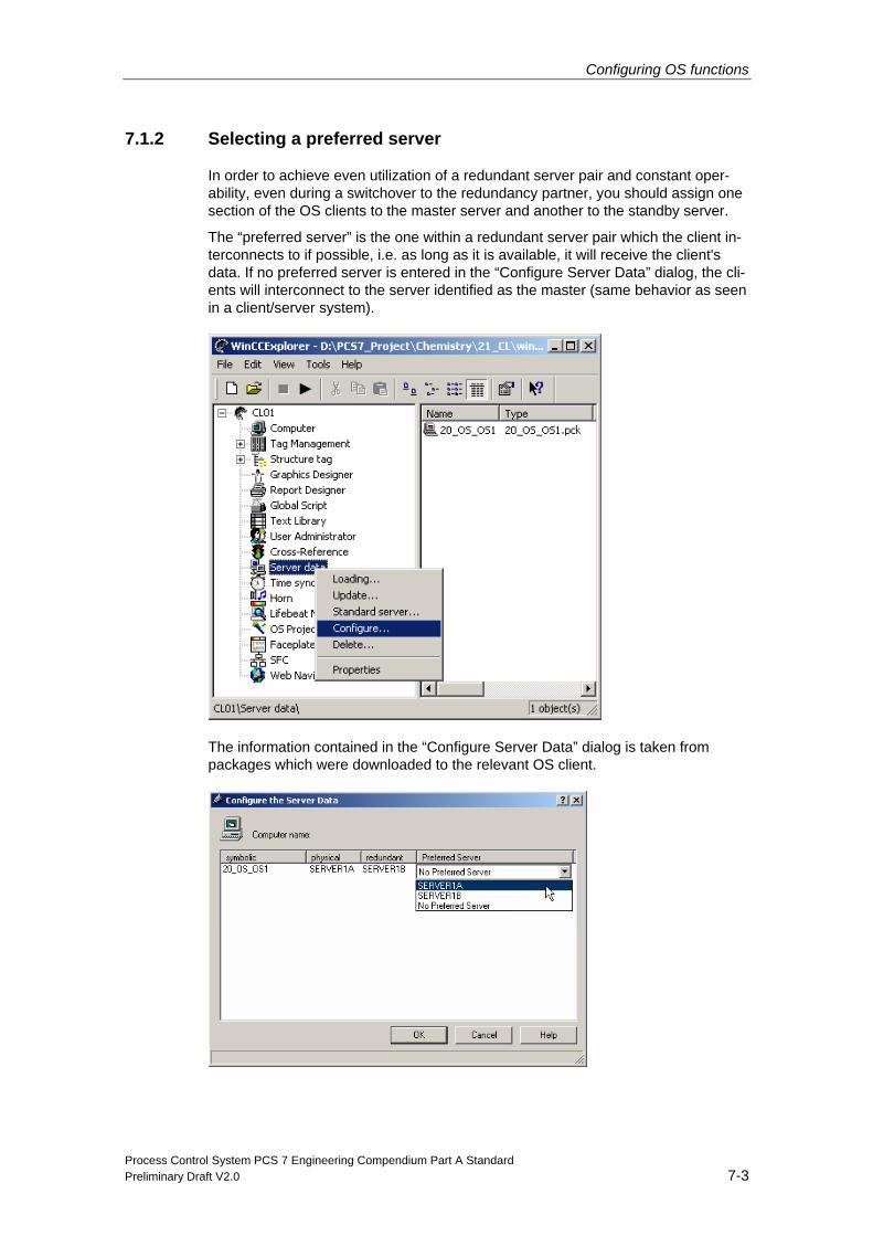
Configuring OS functions
Process Control System PCS 7 Engineering Compendium Part A Standard Preliminary Draft V2.0 7-3
7.1.2 Selecting a preferred server
In order to achieve even utilization of a redundant server pair and constant oper-ability, even during a switchover to the redundancy partner, you should assign one section of the OS clients to the master server and another to the standby server.
The “preferred server” is the one within a redundant server pair which the client in-terconnects to if possible, i.e. as long as it is available, it will receive the client's data. If no preferred server is entered in the “Configure Server Data” dialog, the cli-ents will interconnect to the server identified as the master (same behavior as seen in a client/server system).
The information contained in the “Configure Server Data” dialog is taken from packages which were downloaded to the relevant OS client.
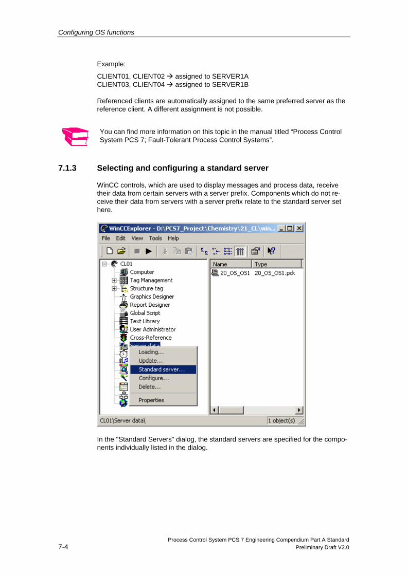
Configuring OS functions
Process Control System PCS 7 Engineering Compendium Part A Standard 7-4 Preliminary Draft V2.0
Example:
CLIENT01, CLIENT02 assigned to SERVER1A CLIENT03, CLIENT04 assigned to SERVER1B Referenced clients are automatically assigned to the same preferred server as the reference client. A different assignment is not possible.
You can find more information on this topic in the manual titled “Process Control System PCS 7; Fault-Tolerant Process Control Systems”.
7.1.3 Selecting and configuring a standard server
WinCC controls, which are used to display messages and process data, receive their data from certain servers with a server prefix. Components which do not re-ceive their data from servers with a server prefix relate to the standard server set here.
In the "Standard Servers" dialog, the standard servers are specified for the compo-nents individually listed in the dialog.
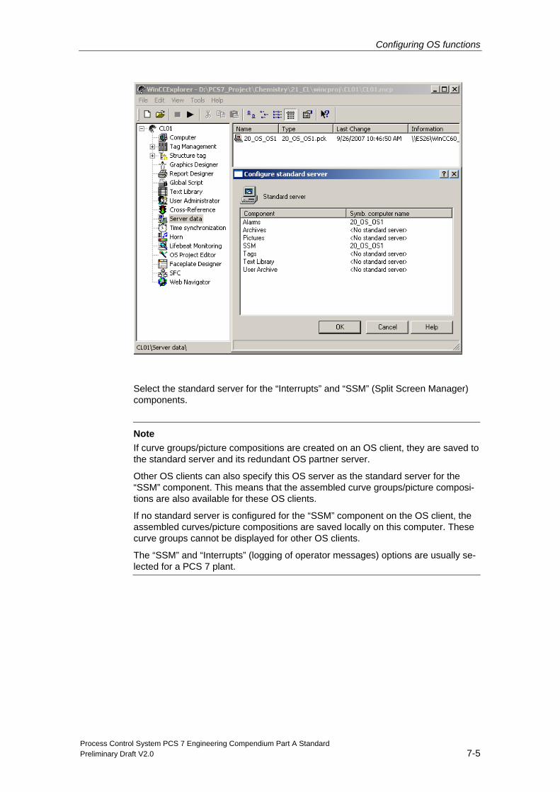
Configuring OS functions
Process Control System PCS 7 Engineering Compendium Part A Standard Preliminary Draft V2.0 7-5
Select the standard server for the “Interrupts” and “SSM” (Split Screen Manager) components.
Note
If curve groups/picture compositions are created on an OS client, they are saved to the standard server and its redundant OS partner server.
Other OS clients can also specify this OS server as the standard server for the “SSM” component. This means that the assembled curve groups/picture composi-tions are also available for these OS clients.
If no standard server is configured for the “SSM” component on the OS client, the assembled curves/picture compositions are saved locally on this computer. These curve groups cannot be displayed for other OS clients.
The “SSM” and “Interrupts” (logging of operator messages) options are usually se-lected for a PCS 7 plant.
Configuring OS functions
Process Control System PCS 7 Engineering Compendium Part A Standard 7-6 Preliminary Draft V2.0
7.1.4 Working with the OS project editor
In the OS project editor you make settings for the user interface which a plant op-erator can use to control and monitor the plant in process mode.
The OS project editor contains the following tabs:
Tab Function
Layout Monitoring the configuration and definition of buttons which the plant op-erator can use to switch between individual areas and servers
Message Configu-ration
Settings for message lists and area assignments
Message Display Configuration of the message system’s runtime behavior and display of messages on message pages or in group displays
Areas Definition of areas which the plant operator can access in the overview area
Runtime Windows Definition of the maximum number of windows which may be open when faceplates and curves are called
Basic Data Selection of objects which must be replaced after a change. The follow-ing objects can be selected:
- Pictures
- Faceplates
- Scripts
General - Settings used by the OS project editor for downloading changes
- A full download must be performed for the “Entire configuration” set-ting.
- Settings for logs which are replaced when the project editor is run
When an OS project is created in the ES, the OS project editor is opened in the background and initialized with default settings. Only if a configuration that deviates from the standard setting is required will you need to start the OS project editor via the WinCC Explorer and configure the desired project settings.
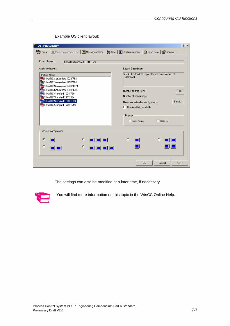
Configuring OS functions
Process Control System PCS 7 Engineering Compendium Part A Standard Preliminary Draft V2.0 7-7
Example OS client layout:
The settings can also be modified at a later time, if necessary.
You will find more information on this topic in the WinCC Online Help.
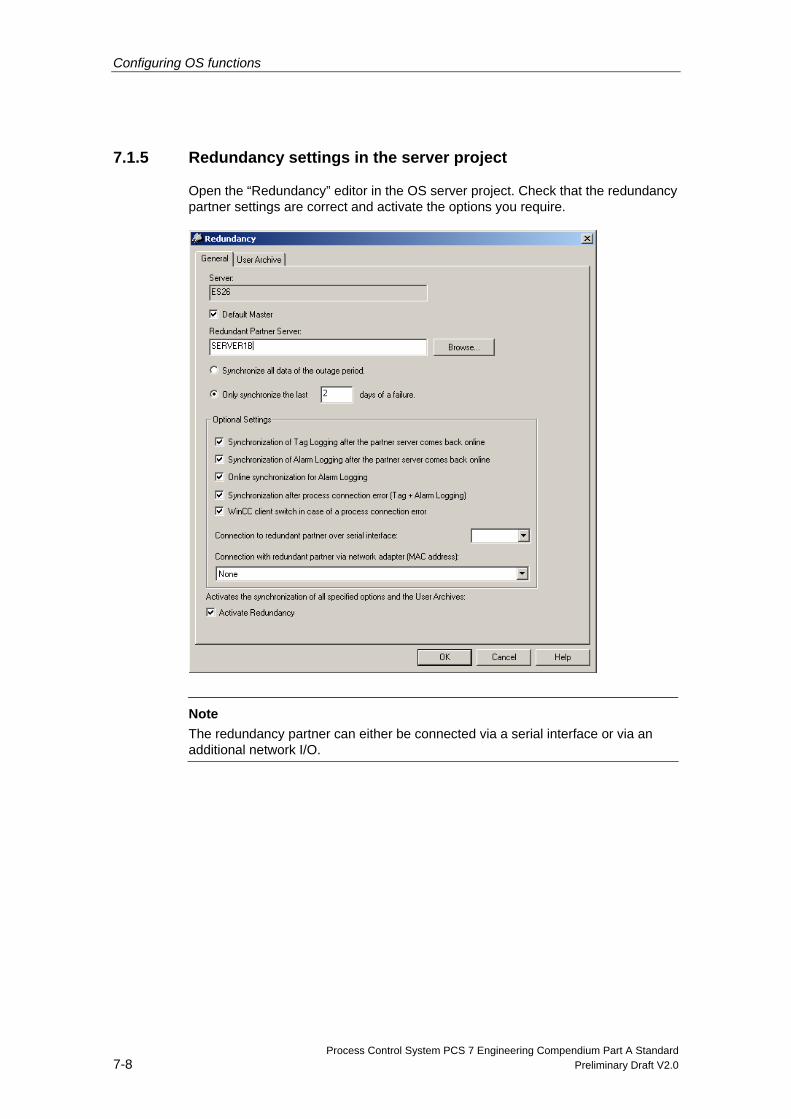
Configuring OS functions
Process Control System PCS 7 Engineering Compendium Part A Standard 7-8 Preliminary Draft V2.0
7.1.5 Redundancy settings in the server project
Open the “Redundancy” editor in the OS server project. Check that the redundancy partner settings are correct and activate the options you require.
Note The redundancy partner can either be connected via a serial interface or via an additional network I/O.
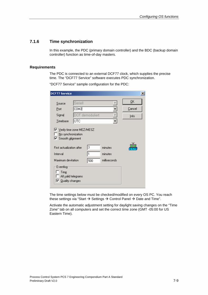
Configuring OS functions
Process Control System PCS 7 Engineering Compendium Part A Standard Preliminary Draft V2.0 7-9
7.1.6 Time synchronization
In this example, the PDC (primary domain controller) and the BDC (backup domain controller) function as time-of-day masters.
Requirements The PDC is connected to an external DCF77 clock, which supplies the precise time. The “DCF77 Service” software executes PDC synchronization.
“DCF77 Service” sample configuration for the PDC:
The time settings below must be checked/modified on every OS PC. You reach these settings via “Start Settings Control Panel Date and Time”.
Activate the automatic adjustment setting for daylight saving changes on the “Time Zone” tab on all computers and set the correct time zone (GMT -05:00 for US Eastern Time).
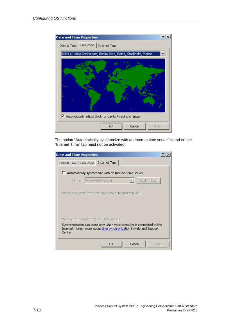
Configuring OS functions
Process Control System PCS 7 Engineering Compendium Part A Standard 7-10 Preliminary Draft V2.0
The option “Automatically synchronize with an Internet time server” found on the “Internet Time” tab must not be activated.
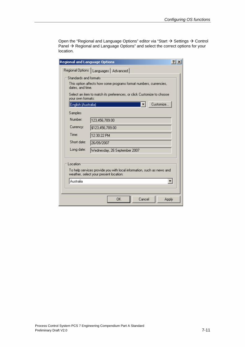
Configuring OS functions
Process Control System PCS 7 Engineering Compendium Part A Standard Preliminary Draft V2.0 7-11
Open the “Regional and Language Options” editor via “Start Settings Control Panel Regional and Language Options” and select the correct options for your location.
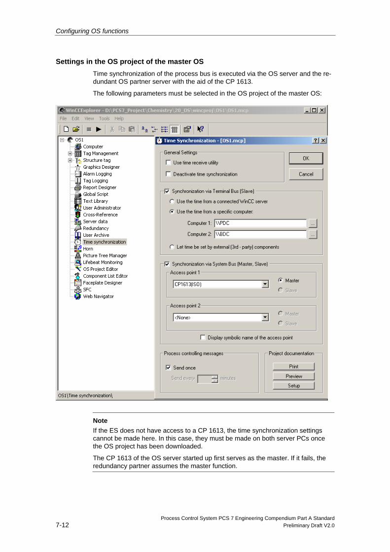
Configuring OS functions
Process Control System PCS 7 Engineering Compendium Part A Standard 7-12 Preliminary Draft V2.0
Settings in the OS project of the master OS Time synchronization of the process bus is executed via the OS server and the re-dundant OS partner server with the aid of the CP 1613.
The following parameters must be selected in the OS project of the master OS:
Note If the ES does not have access to a CP 1613, the time synchronization settings cannot be made here. In this case, they must be made on both server PCs once the OS project has been downloaded.
The CP 1613 of the OS server started up first serves as the master. If it fails, the redundancy partner assumes the master function.
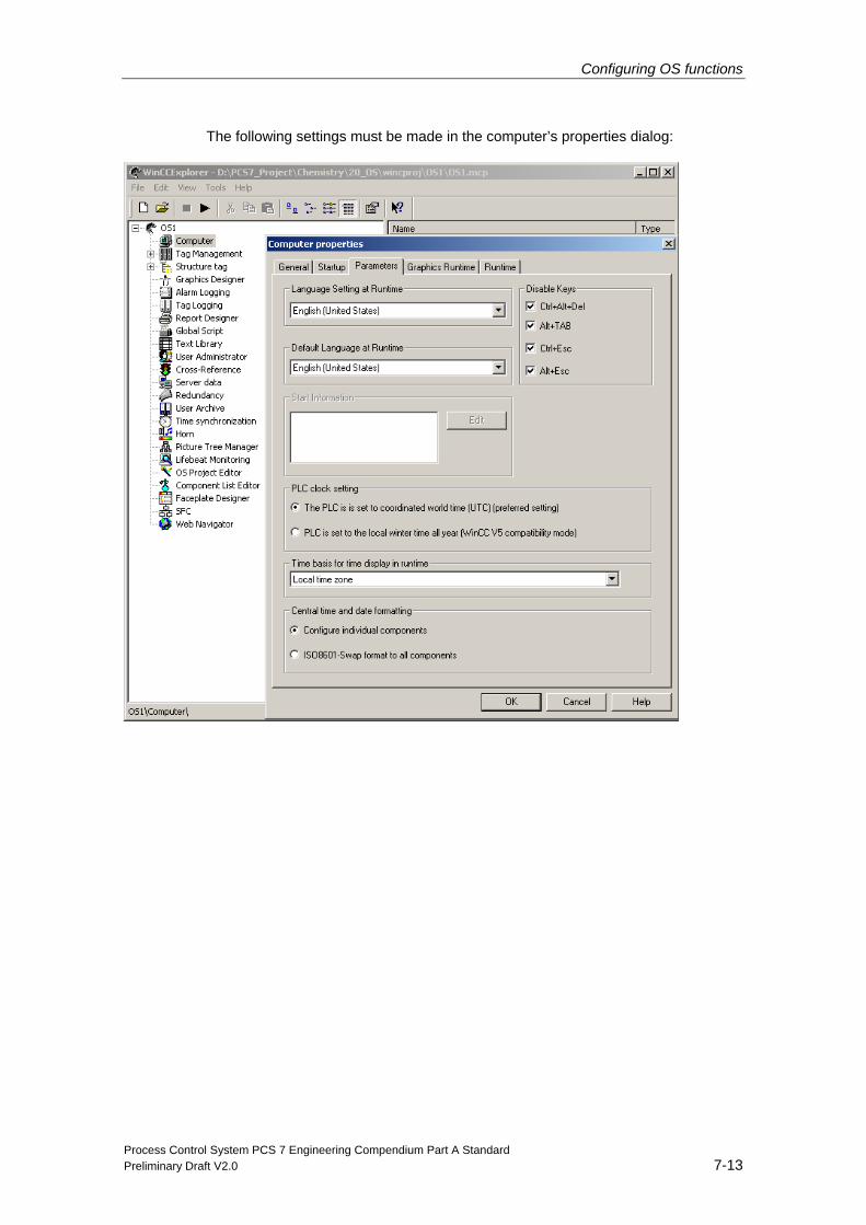
Configuring OS functions
Process Control System PCS 7 Engineering Compendium Part A Standard Preliminary Draft V2.0 7-13
The following settings must be made in the computer’s properties dialog:
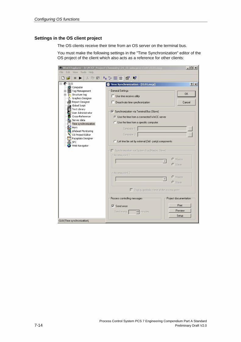
Configuring OS functions
Process Control System PCS 7 Engineering Compendium Part A Standard 7-14 Preliminary Draft V2.0
Settings in the OS client project The OS clients receive their time from an OS server on the terminal bus.
You must make the following settings in the "Time Synchronization" editor of the OS project of the client which also acts as a reference for other clients:
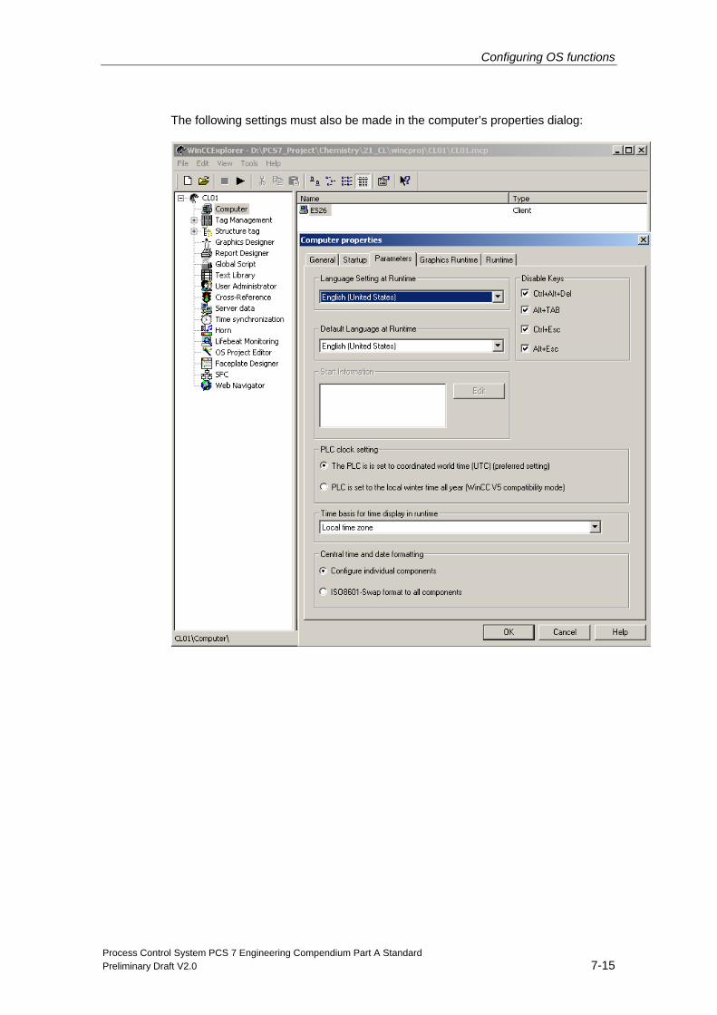
Configuring OS functions
Process Control System PCS 7 Engineering Compendium Part A Standard Preliminary Draft V2.0 7-15
The following settings must also be made in the computer’s properties dialog:
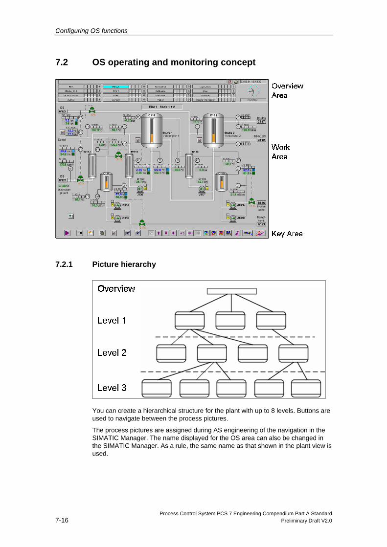
Configuring OS functions
Process Control System PCS 7 Engineering Compendium Part A Standard 7-16 Preliminary Draft V2.0
7.2 OS operating and monitoring concept
7.2.1 Picture hierarchy
You can create a hierarchical structure for the plant with up to 8 levels. Buttons are used to navigate between the process pictures.
The process pictures are assigned during AS engineering of the navigation in the SIMATIC Manager. The name displayed for the OS area can also be changed in the SIMATIC Manager. As a rule, the same name as that shown in the plant view is used.
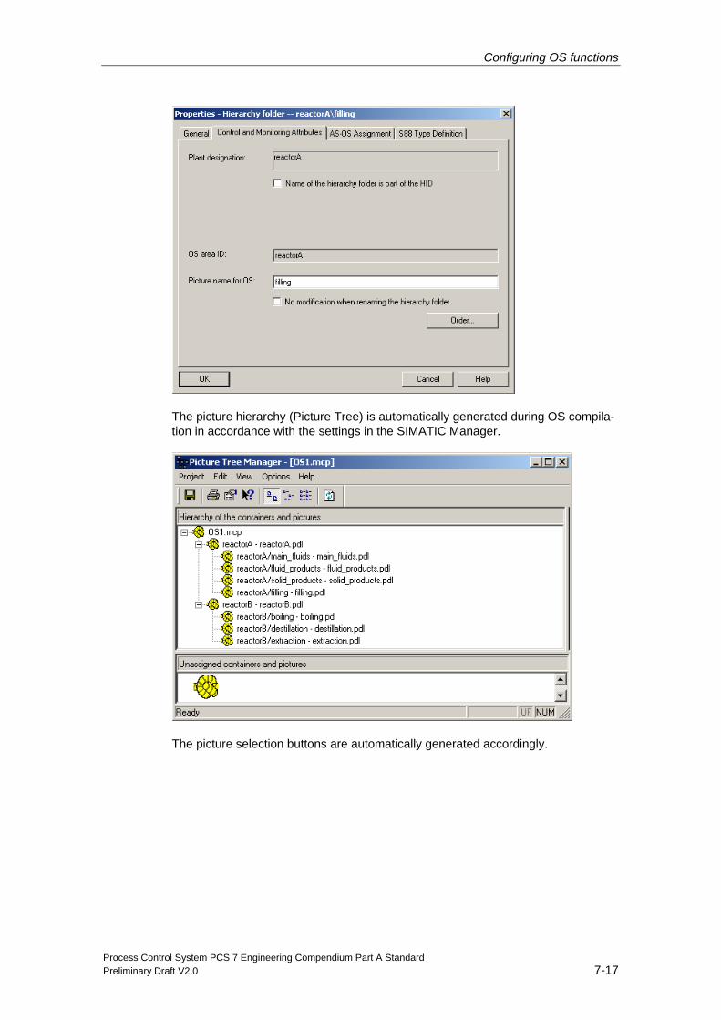
Configuring OS functions
Process Control System PCS 7 Engineering Compendium Part A Standard Preliminary Draft V2.0 7-17
The picture hierarchy (Picture Tree) is automatically generated during OS compila-tion in accordance with the settings in the SIMATIC Manager.
The picture selection buttons are automatically generated accordingly.
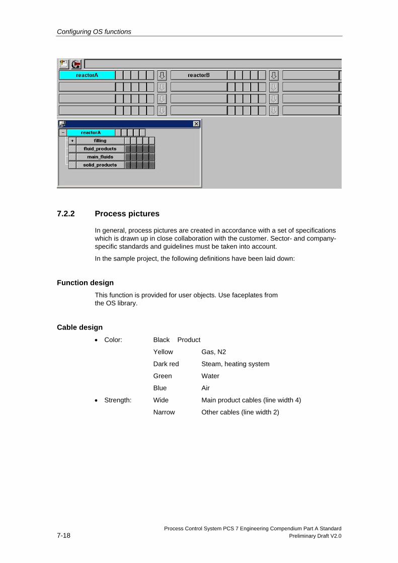
Configuring OS functions
Process Control System PCS 7 Engineering Compendium Part A Standard 7-18 Preliminary Draft V2.0
7.2.2 Process pictures
In general, process pictures are created in accordance with a set of specifications which is drawn up in close collaboration with the customer. Sector- and company-specific standards and guidelines must be taken into account.
In the sample project, the following definitions have been laid down:
Function design This function is provided for user objects. Use faceplates from the OS library.
Cable design • Color: Black Product
Yellow Gas, N2
Dark red Steam, heating system
Green Water
Blue Air
• Strength: Wide Main product cables (line width 4)
Narrow Other cables (line width 2)
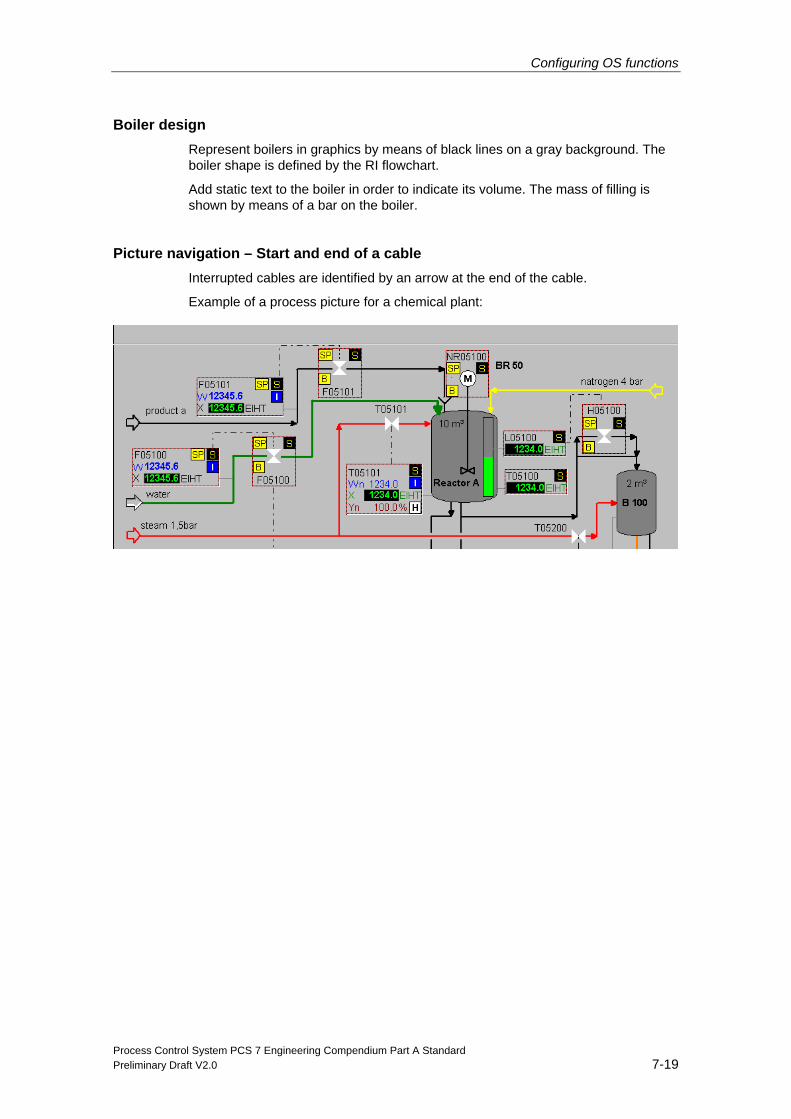
Configuring OS functions
Process Control System PCS 7 Engineering Compendium Part A Standard Preliminary Draft V2.0 7-19
Boiler design Represent boilers in graphics by means of black lines on a gray background. The boiler shape is defined by the RI flowchart.
Add static text to the boiler in order to indicate its volume. The mass of filling is shown by means of a bar on the boiler.
Picture navigation – Start and end of a cable Interrupted cables are identified by an arrow at the end of the cable.
Example of a process picture for a chemical plant:
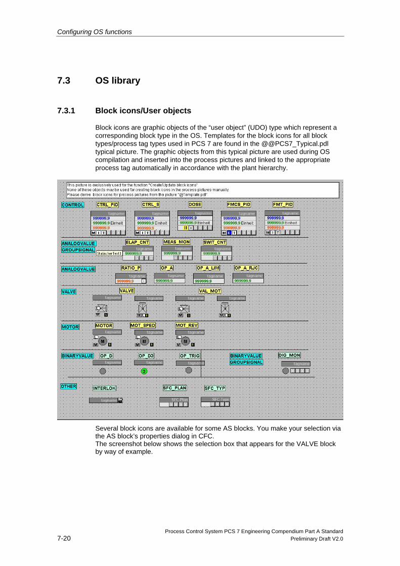
Configuring OS functions
Process Control System PCS 7 Engineering Compendium Part A Standard 7-20 Preliminary Draft V2.0
7.3 OS library
7.3.1 Block icons/User objects
Block icons are graphic objects of the “user object” (UDO) type which represent a corresponding block type in the OS. Templates for the block icons for all block types/process tag types used in PCS 7 are found in the @@PCS7_Typical.pdl typical picture. The graphic objects from this typical picture are used during OS compilation and inserted into the process pictures and linked to the appropriate process tag automatically in accordance with the plant hierarchy.
Several block icons are available for some AS blocks. You make your selection via the AS block’s properties dialog in CFC. The screenshot below shows the selection box that appears for the VALVE block by way of example.
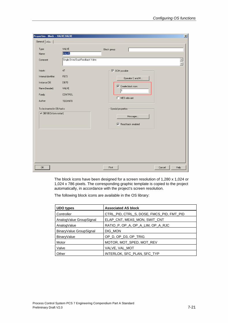
Configuring OS functions
Process Control System PCS 7 Engineering Compendium Part A Standard Preliminary Draft V2.0 7-21
The block icons have been designed for a screen resolution of 1,280 x 1,024 or 1,024 x 786 pixels. The corresponding graphic template is copied to the project automatically, in accordance with the project’s screen resolution.
The following block icons are available in the OS library:
UDO types Associated AS block
Controller CTRL_PID, CTRL_S, DOSE, FMCS_PID, FMT_PID AnalogValue GroupSignal ELAP_CNT, MEAS_MON, SWIT_CNT AnalogValue RATIO_P, OP_A, OP_A_LIM, OP_A_RJC BinaryValue GroupSignal DIG_MON BinaryValue OP_D, OP_D3, OP_TRIG Motor MOTOR, MOT_SPED, MOT_REV Valve VALVE, VAL_MOT Other INTERLOK, SFC_PLAN, SFC_TYP
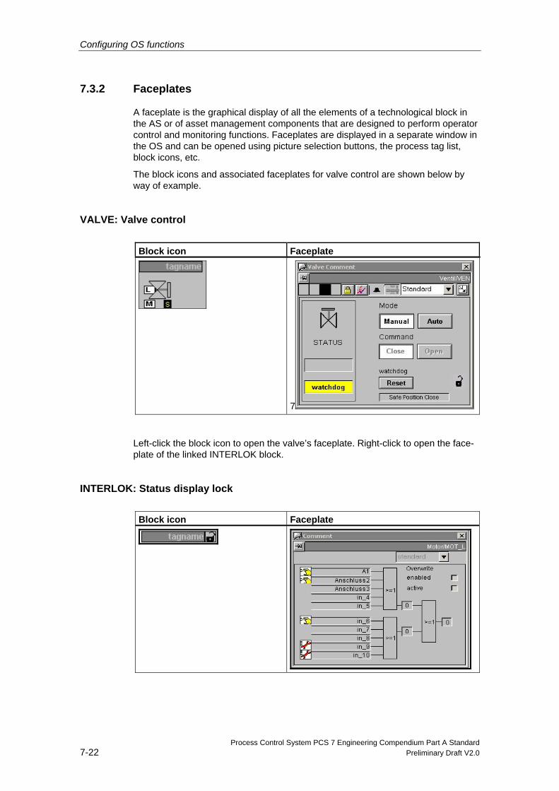
Configuring OS functions
Process Control System PCS 7 Engineering Compendium Part A Standard 7-22 Preliminary Draft V2.0
7.3.2 Faceplates
A faceplate is the graphical display of all the elements of a technological block in the AS or of asset management components that are designed to perform operator control and monitoring functions. Faceplates are displayed in a separate window in the OS and can be opened using picture selection buttons, the process tag list, block icons, etc.
The block icons and associated faceplates for valve control are shown below by way of example.
VALVE: Valve control
Block icon Faceplate
7
Left-click the block icon to open the valve’s faceplate. Right-click to open the face-plate of the linked INTERLOK block.
INTERLOK: Status display lock
Block icon Faceplate
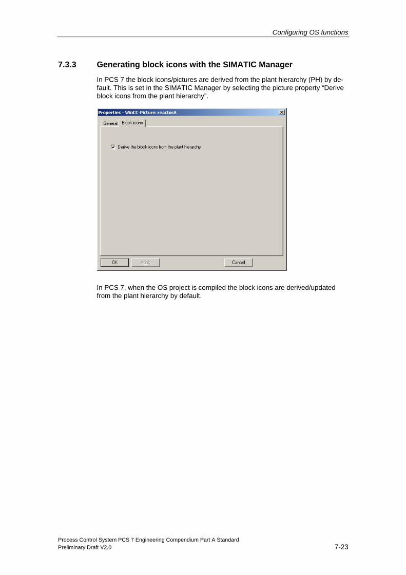
Configuring OS functions
Process Control System PCS 7 Engineering Compendium Part A Standard Preliminary Draft V2.0 7-23
7.3.3 Generating block icons with the SIMATIC Manager
In PCS 7 the block icons/pictures are derived from the plant hierarchy (PH) by de-fault. This is set in the SIMATIC Manager by selecting the picture property “Derive block icons from the plant hierarchy”.
In PCS 7, when the OS project is compiled the block icons are derived/updated from the plant hierarchy by default.
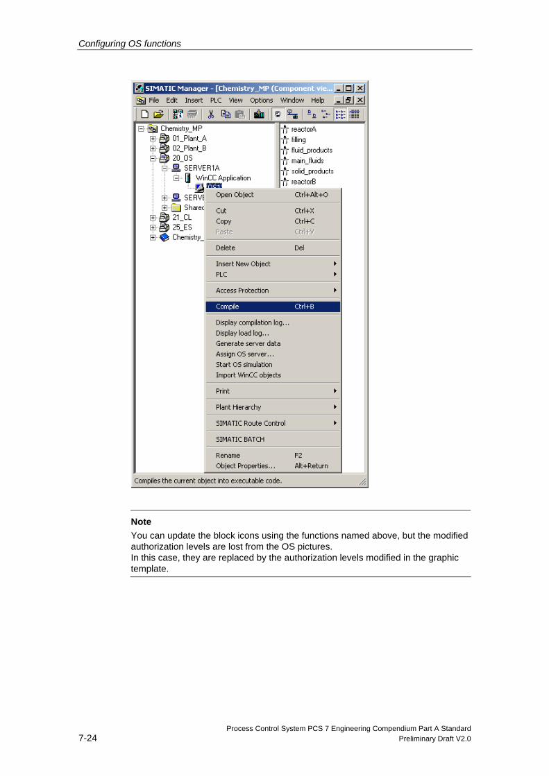
Configuring OS functions
Process Control System PCS 7 Engineering Compendium Part A Standard 7-24 Preliminary Draft V2.0
Note
You can update the block icons using the functions named above, but the modified authorization levels are lost from the OS pictures. In this case, they are replaced by the authorization levels modified in the graphic template.
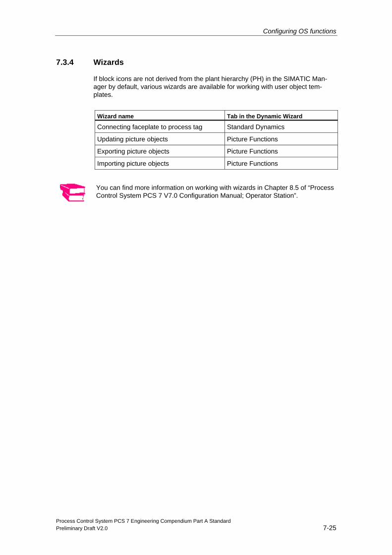
Configuring OS functions
Process Control System PCS 7 Engineering Compendium Part A Standard Preliminary Draft V2.0 7-25
7.3.4 Wizards
If block icons are not derived from the plant hierarchy (PH) in the SIMATIC Man-ager by default, various wizards are available for working with user object tem-plates.
Wizard name Tab in the Dynamic Wizard
Connecting faceplate to process tag Standard Dynamics
Updating picture objects Picture Functions
Exporting picture objects Picture Functions
Importing picture objects Picture Functions
You can find more information on working with wizards in Chapter 8.5 of “Process Control System PCS 7 V7.0 Configuration Manual; Operator Station”.
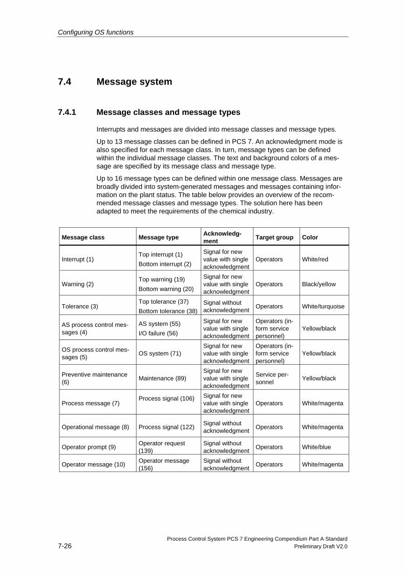
Configuring OS functions
Process Control System PCS 7 Engineering Compendium Part A Standard 7-26 Preliminary Draft V2.0
7.4 Message system
7.4.1 Message classes and message types
Interrupts and messages are divided into message classes and message types.
Up to 13 message classes can be defined in PCS 7. An acknowledgment mode is also specified for each message class. In turn, message types can be defined within the individual message classes. The text and background colors of a mes-sage are specified by its message class and message type.
Up to 16 message types can be defined within one message class. Messages are broadly divided into system-generated messages and messages containing infor-mation on the plant status. The table below provides an overview of the recom-mended message classes and message types. The solution here has been adapted to meet the requirements of the chemical industry.
Message class Message type Acknowledg-ment Target group Color
Interrupt (1) Top interrupt (1) Bottom interrupt (2)
Signal for new value with single acknowledgment
Operators White/red
Warning (2) Top warning (19) Bottom warning (20)
Signal for new value with single acknowledgment
Operators Black/yellow
Tolerance (3) Top tolerance (37) Bottom tolerance (38)
Signal without acknowledgment Operators White/turquoise
AS process control mes-sages (4)
AS system (55) I/O failure (56)
Signal for new value with single acknowledgment
Operators (in-form service personnel)
Yellow/black
OS process control mes-sages (5) OS system (71)
Signal for new value with single acknowledgment
Operators (in-form service personnel)
Yellow/black
Preventive maintenance (6) Maintenance (89)
Signal for new value with single acknowledgment
Service per-sonnel Yellow/black
Process message (7) Process signal (106)
Signal for new value with single acknowledgment
Operators White/magenta
Operational message (8) Process signal (122) Signal without acknowledgment Operators White/magenta
Operator prompt (9) Operator request (139)
Signal without acknowledgment Operators White/blue
Operator message (10) Operator message (156)
Signal without acknowledgment Operators White/magenta
Configuring OS functions
Process Control System PCS 7 Engineering Compendium Part A Standard Preliminary Draft V2.0 7-27
Message class Message type Acknowledg-ment Target group Color
Status message Status AS (253) Status OS (254)
Signal without acknowledgment Operators White/petrol
Alarm, warning, and tolerance messages …indicate that a limit value has been exceeded. These limit values have been de-fined in the user-configured CFC. The Interrupt message class is usually used for emergency stop and other high-priority binary messages too. The messages/signals are aimed at the operator.
AS process control messages …provide information about errors in I/O peripherals and in the system, e.g. wire break, short-circuit, channel error, module failure, access error, redundancy failure, or failure of the auxiliary current. If a system-generated message or signal is dis-played, the operator must inform the service team without delay.
OS process control messages …provide information about errors in the OS system, e.g. errors relating to data-base access, failure of OS server redundancy, errors relating to time synchroniza-tion. If a system-generated message or a signal for field instruments is displayed, the operator must inform the service team without delay.
Preventive maintenance ...indicates that service personnel will soon have to take a look at equip-ment/components (due to a dirty sensor, for example).
Process messages …are specified on a user-specific basis.
Operational messages …provide information about the plant status during conventional operation (e.g. “Temperature setpoint reached”).
Operator prompts …are messages generated by the sequential control or stacking systems which prompt the operator to perform certain tasks.
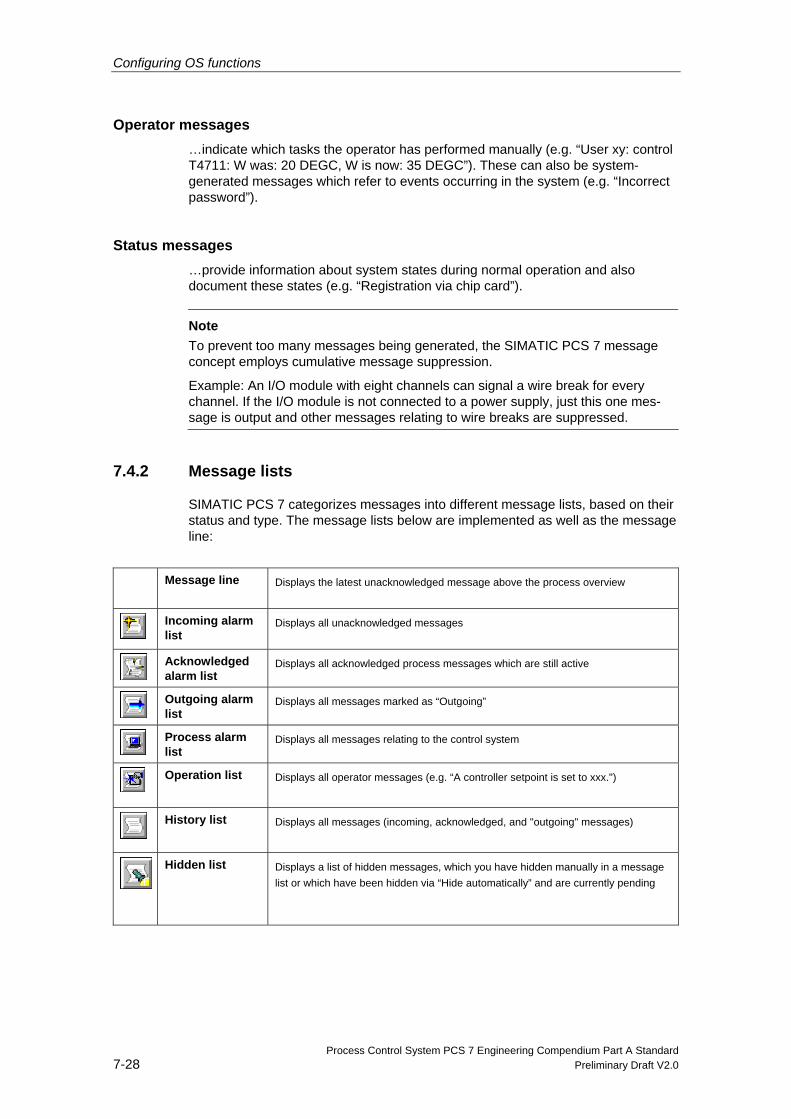
Configuring OS functions
Process Control System PCS 7 Engineering Compendium Part A Standard 7-28 Preliminary Draft V2.0
Operator messages …indicate which tasks the operator has performed manually (e.g. “User xy: control T4711: W was: 20 DEGC, W is now: 35 DEGC”). These can also be system-generated messages which refer to events occurring in the system (e.g. “Incorrect password”).
Status messages …provide information about system states during normal operation and also document these states (e.g. “Registration via chip card”).
Note To prevent too many messages being generated, the SIMATIC PCS 7 message concept employs cumulative message suppression.
Example: An I/O module with eight channels can signal a wire break for every channel. If the I/O module is not connected to a power supply, just this one mes-sage is output and other messages relating to wire breaks are suppressed.
7.4.2 Message lists
SIMATIC PCS 7 categorizes messages into different message lists, based on their status and type. The message lists below are implemented as well as the message line:
Message line Displays the latest unacknowledged message above the process overview
Incoming alarm list
Displays all unacknowledged messages
Acknowledged alarm list
Displays all acknowledged process messages which are still active
Outgoing alarm list
Displays all messages marked as “Outgoing”
Process alarm list
Displays all messages relating to the control system
Operation list Displays all operator messages (e.g. “A controller setpoint is set to xxx.")
History list Displays all messages (incoming, acknowledged, and "outgoing" messages)
Hidden list Displays a list of hidden messages, which you have hidden manually in a message list or which have been hidden via “Hide automatically” and are currently pending
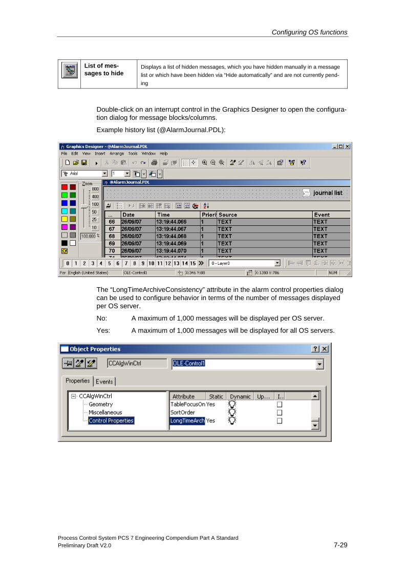
Configuring OS functions
Process Control System PCS 7 Engineering Compendium Part A Standard Preliminary Draft V2.0 7-29
List of mes-sages to hide
Displays a list of hidden messages, which you have hidden manually in a message list or which have been hidden via “Hide automatically” and are not currently pend-ing
Double-click on an interrupt control in the Graphics Designer to open the configura-tion dialog for message blocks/columns.
Example history list (@AlarmJournal.PDL):
The “LongTimeArchiveConsistency” attribute in the alarm control properties dialog can be used to configure behavior in terms of the number of messages displayed per OS server.
No: A maximum of 1,000 messages will be displayed per OS server.
Yes: A maximum of 1,000 messages will be displayed for all OS servers.
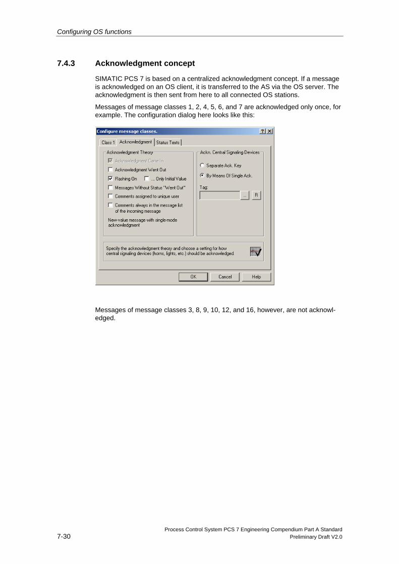
Configuring OS functions
Process Control System PCS 7 Engineering Compendium Part A Standard 7-30 Preliminary Draft V2.0
7.4.3 Acknowledgment concept
SIMATIC PCS 7 is based on a centralized acknowledgment concept. If a message is acknowledged on an OS client, it is transferred to the AS via the OS server. The acknowledgment is then sent from here to all connected OS stations.
Messages of message classes 1, 2, 4, 5, 6, and 7 are acknowledged only once, for example. The configuration dialog here looks like this:
Messages of message classes 3, 8, 9, 10, 12, and 16, however, are not acknowl-edged.
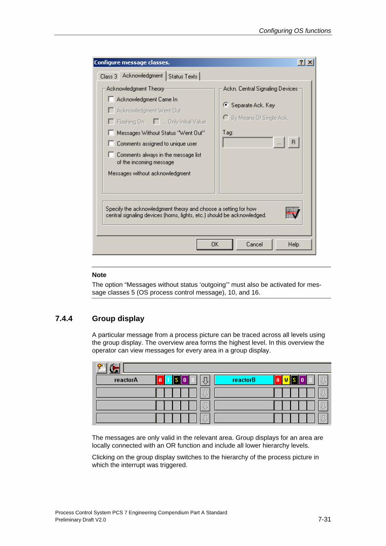
Configuring OS functions
Process Control System PCS 7 Engineering Compendium Part A Standard Preliminary Draft V2.0 7-31
Note The option “Messages without status ‘outgoing’” must also be activated for mes-sage classes 5 (OS process control message), 10, and 16.
7.4.4 Group display
A particular message from a process picture can be traced across all levels using the group display. The overview area forms the highest level. In this overview the operator can view messages for every area in a group display.
The messages are only valid in the relevant area. Group displays for an area are locally connected with an OR function and include all lower hierarchy levels.
Clicking on the group display switches to the hierarchy of the process picture in which the interrupt was triggered.
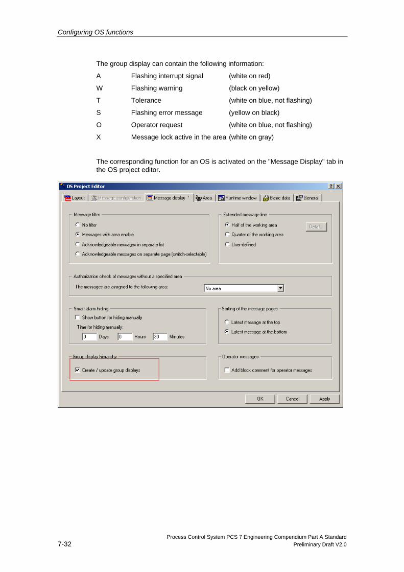
Configuring OS functions
Process Control System PCS 7 Engineering Compendium Part A Standard 7-32 Preliminary Draft V2.0
The group display can contain the following information:
A Flashing interrupt signal (white on red)
W Flashing warning (black on yellow)
T Tolerance (white on blue, not flashing)
S Flashing error message (yellow on black)
O Operator request (white on blue, not flashing)
X Message lock active in the area (white on gray)
The corresponding function for an OS is activated on the "Message Display" tab in the OS project editor.
Configuring OS functions
Process Control System PCS 7 Engineering Compendium Part A Standard Preliminary Draft V2.0 7-33
7.4.5 Audible interrupt signaling
Process failures and errors can be indicated by audible signals as well as in the message list. The signals are output via a signal module.
You can find information on the function and installation of signal modules in the manual titled “Process Control System PCS 7; WinCC Basic Process Control”.
7.4.6 Time stamp
Messages are generated in different areas and at various positions within PCS 7. The origin of the message will, therefore, affect its time stamp.
All messages are archived and are displayed in the same way, regardless of their origin. AS and I/O messages are forwarded to the OS servers separately via the process bus. They already contain the appropriate time stamp. The OS server ar-ranges all messages in the correct order.
To ensure that the correct time stamp is always available, you must configure time synchronization between all the components of the PCS 7 project.
Origin Configuration of the
message text Time stamp place of origin
Meaning in PCS 7
Operator station (OS) In OS “alarm logging” In the OS OS system messages
Automation system (AS)
In the instances of the function block (e.g. CTRL_PID or MEAS_MON)
In the AS Process messages and AS system messages from the SIMATIC station
Distributed I/O (ET 200M)
In the instances of function block IM_DRV
In the ET 200M via the IM 153-2
Selected initial-value-acquisition events in the event of a plant failure (10 ms accuracy)
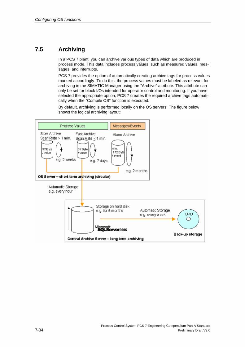
Configuring OS functions
Process Control System PCS 7 Engineering Compendium Part A Standard 7-34 Preliminary Draft V2.0
7.5 Archiving In a PCS 7 plant, you can archive various types of data which are produced in process mode. This data includes process values, such as measured values, mes-sages, and interrupts. PCS 7 provides the option of automatically creating archive tags for process values marked accordingly. To do this, the process values must be labeled as relevant for archiving in the SIMATIC Manager using the "Archive" attribute. This attribute can only be set for block I/Os intended for operator control and monitoring. If you have selected the appropriate option, PCS 7 creates the required archive tags automati-cally when the “Compile OS” function is executed. By default, archiving is performed locally on the OS servers. The figure below shows the logical archiving layout:
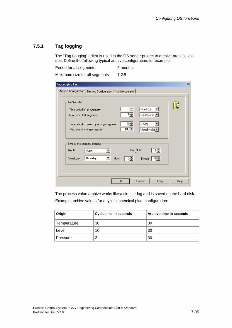
Configuring OS functions
Process Control System PCS 7 Engineering Compendium Part A Standard Preliminary Draft V2.0 7-35
7.5.1 Tag logging
The “Tag Logging” editor is used in the OS server project to archive process val-ues. Define the following typical archive configuration, for example:
Period for all segments: 6 months
Maximum size for all segments 7 GB
The process value archive works like a circular log and is saved on the hard disk.
Example archive values for a typical chemical plant configuration:
Origin Cycle time in seconds Archive time in seconds
Temperature 30 30
Level 10 30
Pressure 2 30
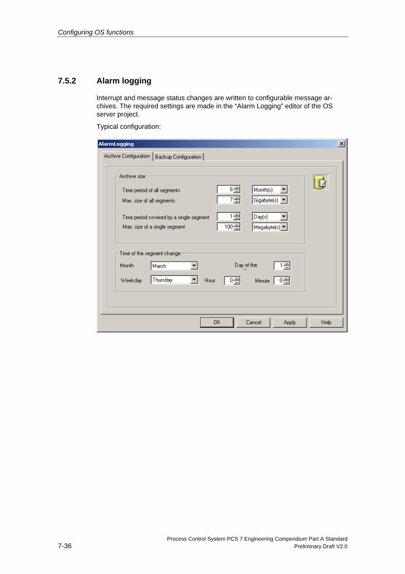
Configuring OS functions
Process Control System PCS 7 Engineering Compendium Part A Standard 7-36 Preliminary Draft V2.0
7.5.2 Alarm logging
Interrupt and message status changes are written to configurable message ar-chives. The required settings are made in the “Alarm Logging” editor of the OS server project.
Typical configuration:
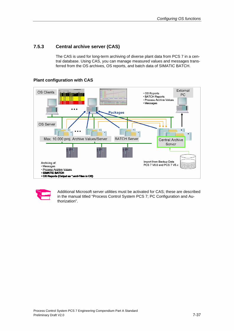
Configuring OS functions
Process Control System PCS 7 Engineering Compendium Part A Standard Preliminary Draft V2.0 7-37
7.5.3 Central archive server (CAS)
The CAS is used for long-term archiving of diverse plant data from PCS 7 in a cen-tral database. Using CAS, you can manage measured values and messages trans-ferred from the OS archives, OS reports, and batch data of SIMATIC BATCH.
Plant configuration with CAS
Additional Microsoft server utilities must be activated for CAS; these are described in the manual titled “Process Control System PCS 7; PC Configuration and Au-thorization”.
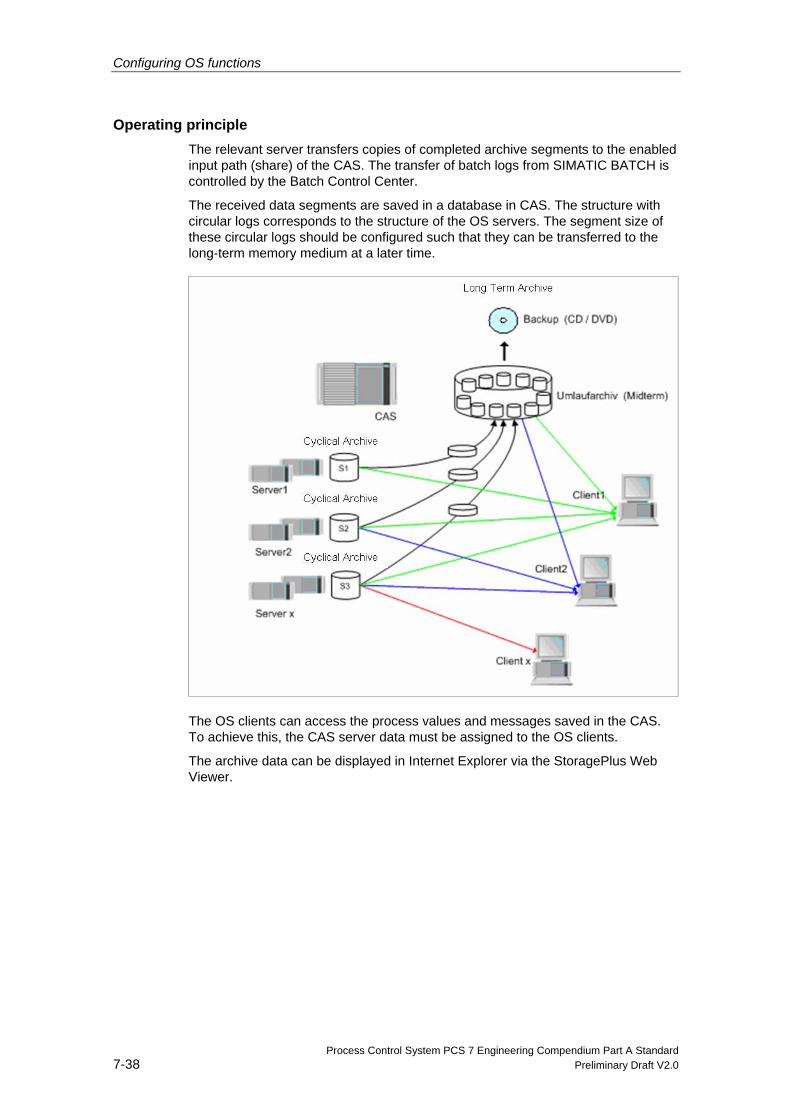
Configuring OS functions
Process Control System PCS 7 Engineering Compendium Part A Standard 7-38 Preliminary Draft V2.0
Operating principle The relevant server transfers copies of completed archive segments to the enabled input path (share) of the CAS. The transfer of batch logs from SIMATIC BATCH is controlled by the Batch Control Center.
The received data segments are saved in a database in CAS. The structure with circular logs corresponds to the structure of the OS servers. The segment size of these circular logs should be configured such that they can be transferred to the long-term memory medium at a later time.
The OS clients can access the process values and messages saved in the CAS. To achieve this, the CAS server data must be assigned to the OS clients.
The archive data can be displayed in Internet Explorer via the StoragePlus Web Viewer.
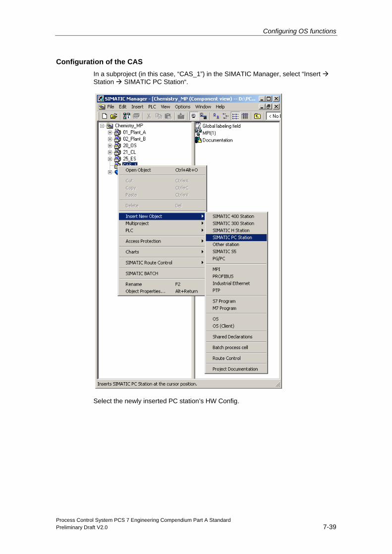
Configuring OS functions
Process Control System PCS 7 Engineering Compendium Part A Standard Preliminary Draft V2.0 7-39
Configuration of the CAS In a subproject (in this case, “CAS_1”) in the SIMATIC Manager, select “Insert Station SIMATIC PC Station“.
Select the newly inserted PC station’s HW Config.
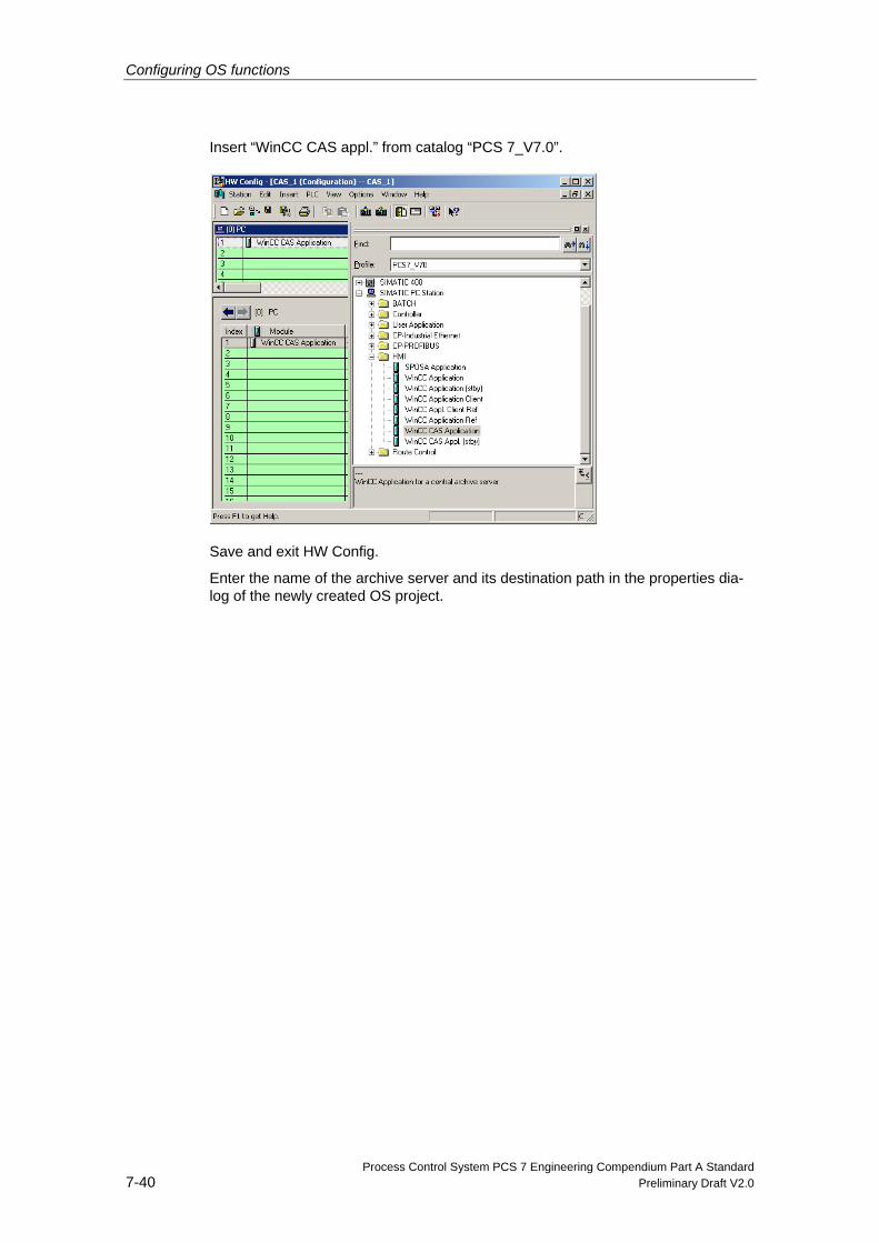
Configuring OS functions
Process Control System PCS 7 Engineering Compendium Part A Standard 7-40 Preliminary Draft V2.0
Insert “WinCC CAS appl.” from catalog “PCS 7_V7.0”.
Save and exit HW Config.
Enter the name of the archive server and its destination path in the properties dia-log of the newly created OS project.
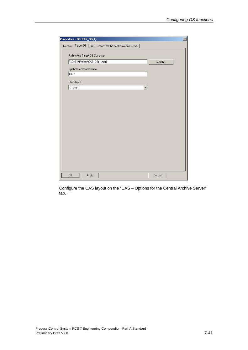
Configuring OS functions
Process Control System PCS 7 Engineering Compendium Part A Standard Preliminary Draft V2.0 7-41
Configure the CAS layout on the “CAS – Options for the Central Archive Server” tab.
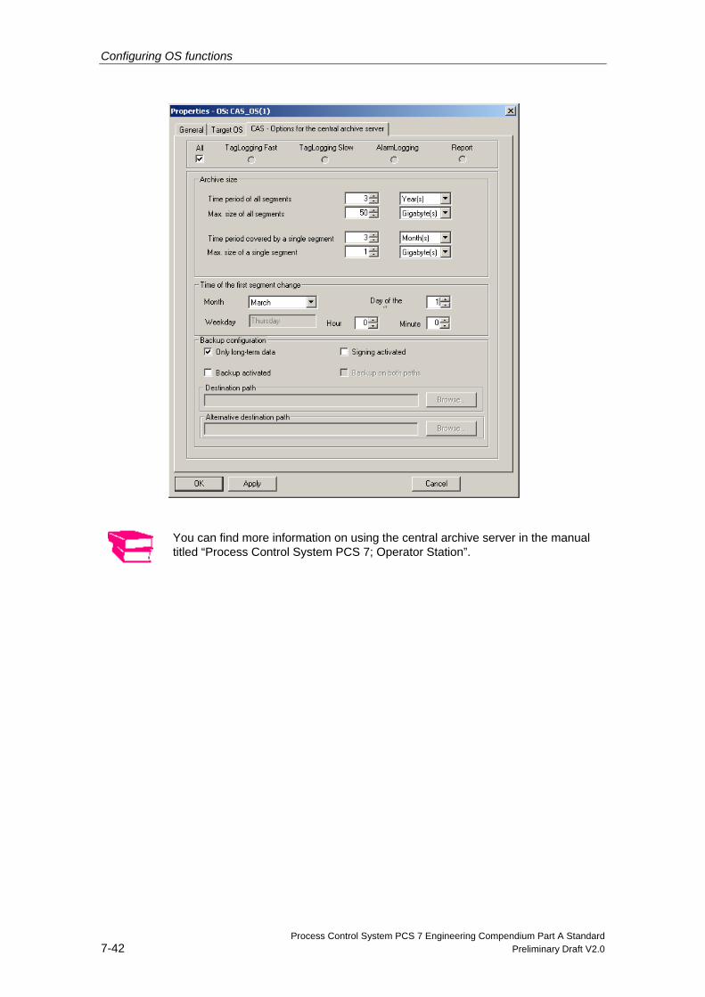
Configuring OS functions
Process Control System PCS 7 Engineering Compendium Part A Standard 7-42 Preliminary Draft V2.0
You can find more information on using the central archive server in the manual titled “Process Control System PCS 7; Operator Station”.

Process Control System PCS 7 Engineering Compendium Part A Standard Preliminary Draft V2.0 8-1
8 Changing and maintaining projects
8.1 Compilation and download in process mode Once you have inserted new plant objects/pictures and tested their function on the ES, you must update the OS servers and OS clients to make the new function available to the process. If no changes have been made to the structure and it is possible to only compile OS changes, the OS servers can remain active during the download procedure. Otherwise, the target project must be deactivated prior to download.
Note Changes are never made to the OS projects on the individual stations directly. All changes are made on the ES and are then downloaded to the stations.
The update procedure can be performed manually (in stages) or automatically, with the help of the “Compile and Download Objects” dialog box.
8.1.1 Manual update procedure during operation
First of all, compile the S7 program in the CFC editor. It does not make any differ-ence to the capacity of the AS to download changes whether "Changes only" or "Entire program" option is selected. Then download the modified S7 program into the AS, which is in the RUN state, using the "Changes only" option.
Now compile the OS project of the master OS, using the "Changes only" option. The system automatically updates server data as part of this process. Download the OS project from the ES to the active servers. As runtime is activated, the “OS Download” dialog only offers the “Changes only” option.
The utility which is then started first performs a delta download to the standby OS. If this process is completed and confirmed with “OK”, a delta download starts to the master OS.
When changes are downloaded to the OS servers the OS clients are also updated automatically, as they receive the package containing the server data again.
Note The steps described should be performed promptly to ensure that no inconsisten-cies arise between the time when the AS is changed and the time when the OS is changed. Operators should be informed of any pending changes.
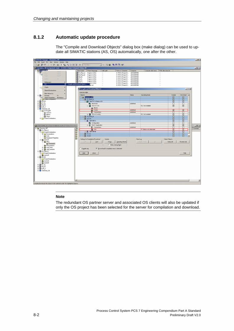
Changing and maintaining projects
Process Control System PCS 7 Engineering Compendium Part A Standard 8-2 Preliminary Draft V2.0
8.1.2 Automatic update procedure
The "Compile and Download Objects” dialog box (make dialog) can be used to up-date all SIMATIC stations (AS, OS) automatically, one after the other.
Note The redundant OS partner server and associated OS clients will also be updated if only the OS project has been selected for the server for compilation and download.
Changing and maintaining projects
Process Control System PCS 7 Engineering Compendium Part A Standard Preliminary Draft V2.0 8-3
8.1.3 Downloading the entire program to a redundant OS server pair
You must always download the entire program as part of the first download proc-ess, or after major changes, such as adding a new AS to the plant, have been made. In such cases, it is only possible to compile the entire program prior to the download.
The following steps must be taken in order to be able to download the entire pro-gram during operation while retaining data archiving and the subsequent update of single stations:
• Compile the project of the master OS (in full or changes only).
• Close the OS project on the master server by deactivating OS runtime and exit-ing the WinCC Explorer. The redundant OS partner server now functions as the master and the OS clients switch over to it.
Note
We recommend that you restart the PC (Master) at this point.
• You can now download the OS project from the ES to the OS server. As run-time is activated, the “OS Download” dialog only offers the “Entire OS” option.
• Wait until a message appears confirming that the download procedure has been completed successfully before reactivating OS server runtime.
• As soon as both OS servers have been run again, the redundancy manager starts to synchronize the data of the redundant OS servers. Wait until the proc-ess control message “REDRT: Archive update complete” appears.
• Now close the OS project on the standby OS. The OS clients switch over again.
Note We recommend that you restart the PC (Slave) station at this point.
• You can now download the OS project to the standby OS.
• If a message appears confirming that the download procedure has been com-pleted successfully, the project has been downloaded in full. As soon as both OS servers have been run again, the redundancy manager starts to synchro-nize data once more. Wait until the process control message “REDRT: Archive update complete” appears.
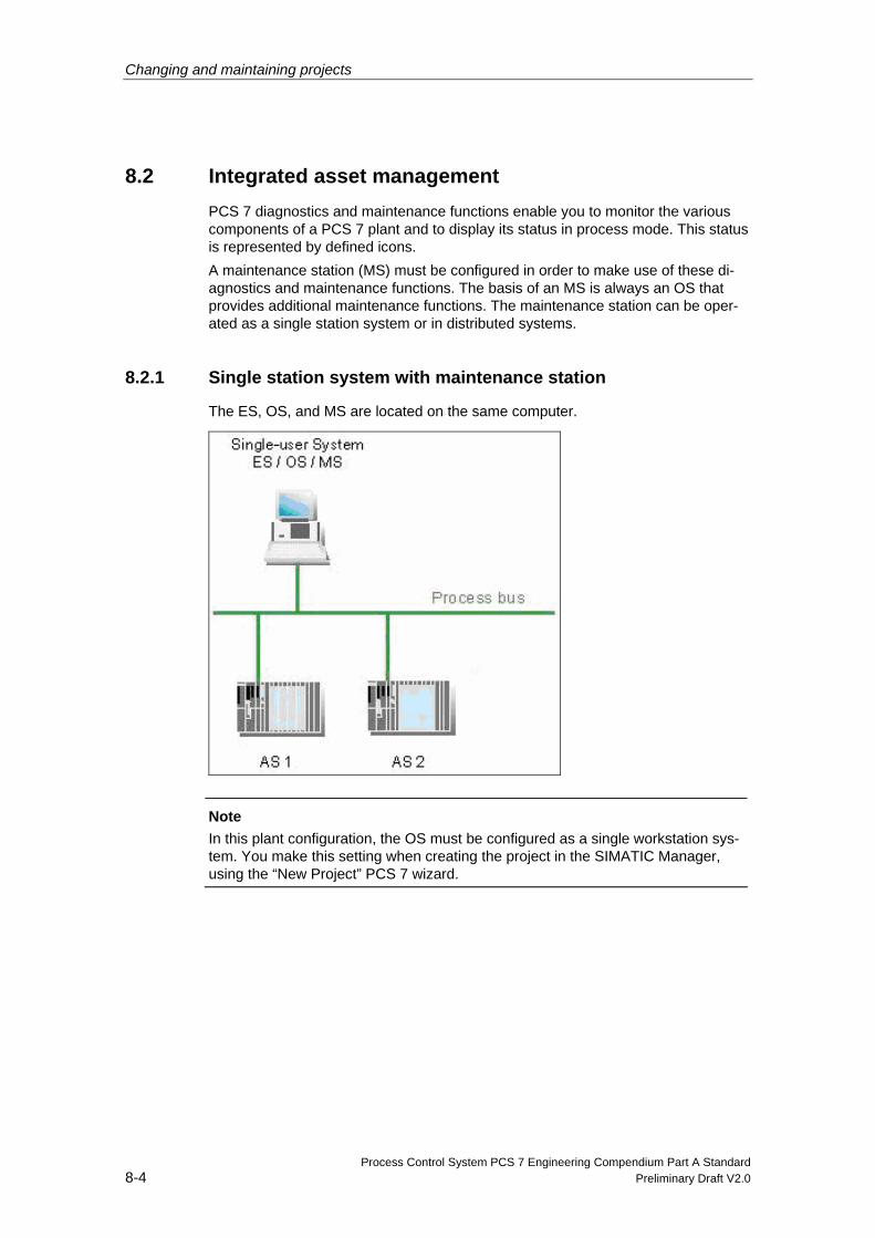
Changing and maintaining projects
Process Control System PCS 7 Engineering Compendium Part A Standard 8-4 Preliminary Draft V2.0
8.2 Integrated asset management PCS 7 diagnostics and maintenance functions enable you to monitor the various components of a PCS 7 plant and to display its status in process mode. This status is represented by defined icons. A maintenance station (MS) must be configured in order to make use of these di-agnostics and maintenance functions. The basis of an MS is always an OS that provides additional maintenance functions. The maintenance station can be oper-ated as a single station system or in distributed systems.
8.2.1 Single station system with maintenance station
The ES, OS, and MS are located on the same computer.
Note In this plant configuration, the OS must be configured as a single workstation sys-tem. You make this setting when creating the project in the SIMATIC Manager, using the “New Project” PCS 7 wizard.
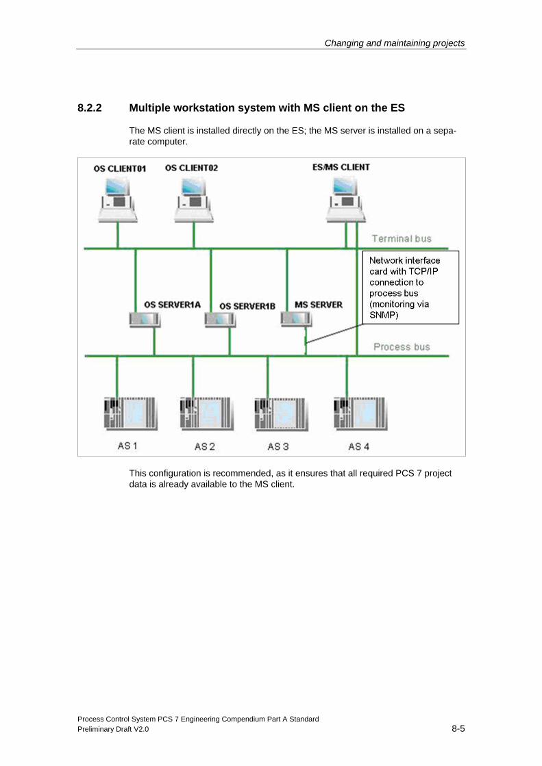
Changing and maintaining projects
Process Control System PCS 7 Engineering Compendium Part A Standard Preliminary Draft V2.0 8-5
8.2.2 Multiple workstation system with MS client on the ES
The MS client is installed directly on the ES; the MS server is installed on a sepa-rate computer.
This configuration is recommended, as it ensures that all required PCS 7 project data is already available to the MS client.
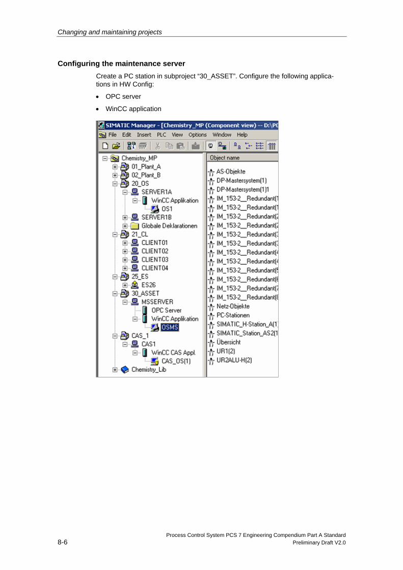
Changing and maintaining projects
Process Control System PCS 7 Engineering Compendium Part A Standard 8-6 Preliminary Draft V2.0
Configuring the maintenance server Create a PC station in subproject “30_ASSET”. Configure the following applica-tions in HW Config:
• OPC server
• WinCC application
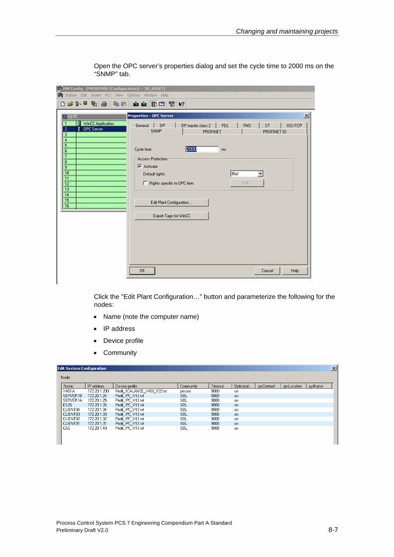
Changing and maintaining projects
Process Control System PCS 7 Engineering Compendium Part A Standard Preliminary Draft V2.0 8-7
Open the OPC server’s properties dialog and set the cycle time to 2000 ms on the “SNMP” tab.
Click the "Edit Plant Configuration…” button and parameterize the following for the nodes:
• Name (note the computer name)
• IP address
• Device profile
• Community
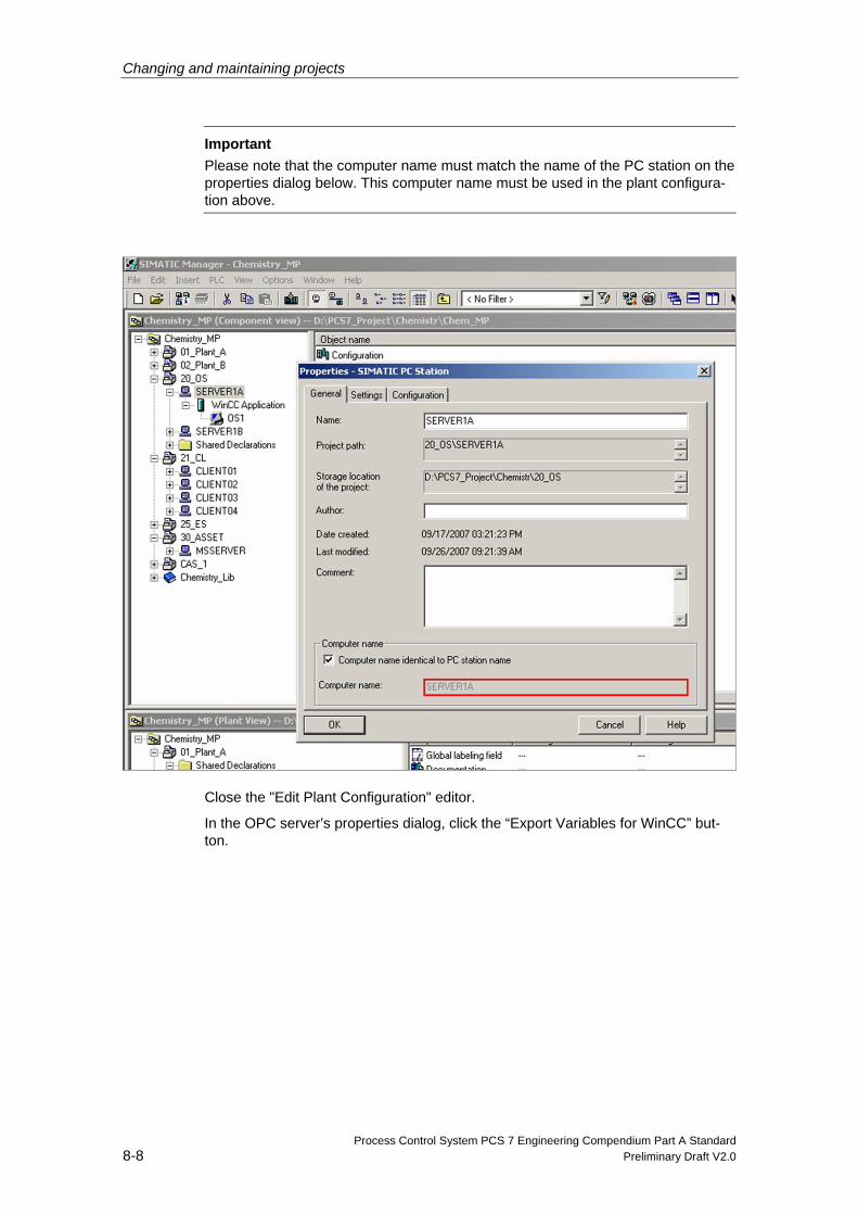
Changing and maintaining projects
Process Control System PCS 7 Engineering Compendium Part A Standard 8-8 Preliminary Draft V2.0
Important Please note that the computer name must match the name of the PC station on the properties dialog below. This computer name must be used in the plant configura-tion above.
Close the "Edit Plant Configuration" editor.
In the OPC server’s properties dialog, click the “Export Variables for WinCC” but-ton.
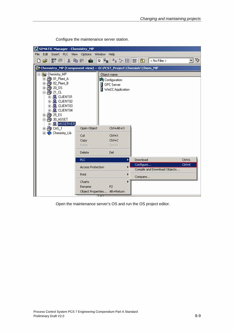
Changing and maintaining projects
Process Control System PCS 7 Engineering Compendium Part A Standard Preliminary Draft V2.0 8-9
Configure the maintenance server station.
Open the maintenance server’s OS and run the OS project editor.
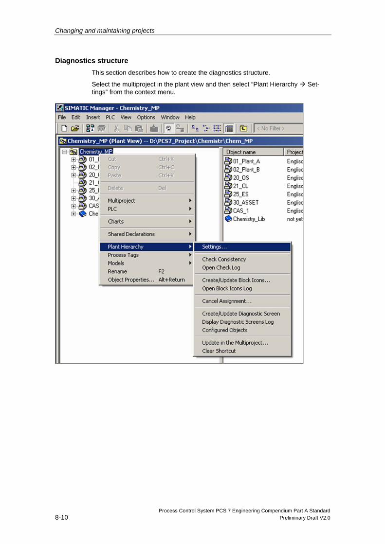
Changing and maintaining projects
Process Control System PCS 7 Engineering Compendium Part A Standard 8-10 Preliminary Draft V2.0
Diagnostics structure This section describes how to create the diagnostics structure.
Select the multiproject in the plant view and then select “Plant Hierarchy Set-tings” from the context menu.
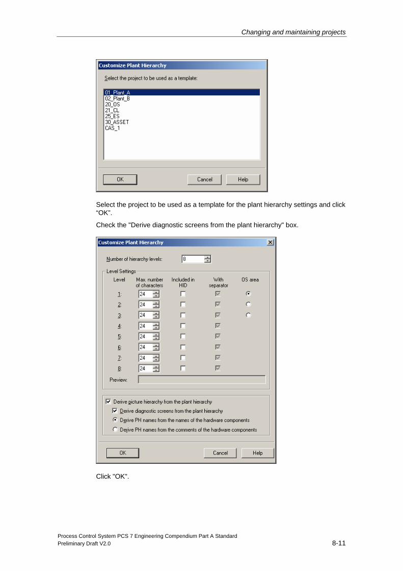
Changing and maintaining projects
Process Control System PCS 7 Engineering Compendium Part A Standard Preliminary Draft V2.0 8-11
Select the project to be used as a template for the plant hierarchy settings and click “OK”.
Check the "Derive diagnostic screens from the plant hierarchy" box.
Click "OK".
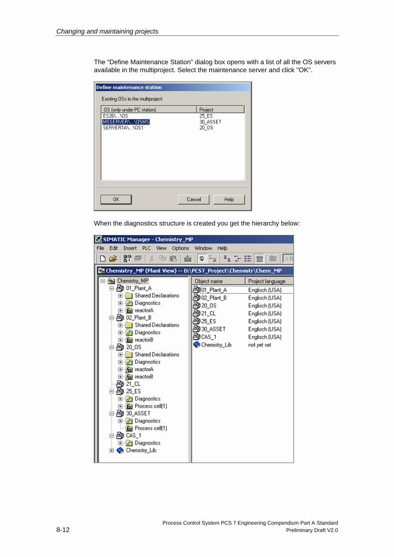
Changing and maintaining projects
Process Control System PCS 7 Engineering Compendium Part A Standard 8-12 Preliminary Draft V2.0
The “Define Maintenance Station” dialog box opens with a list of all the OS servers available in the multiproject. Select the maintenance server and click "OK".
When the diagnostics structure is created you get the hierarchy below:
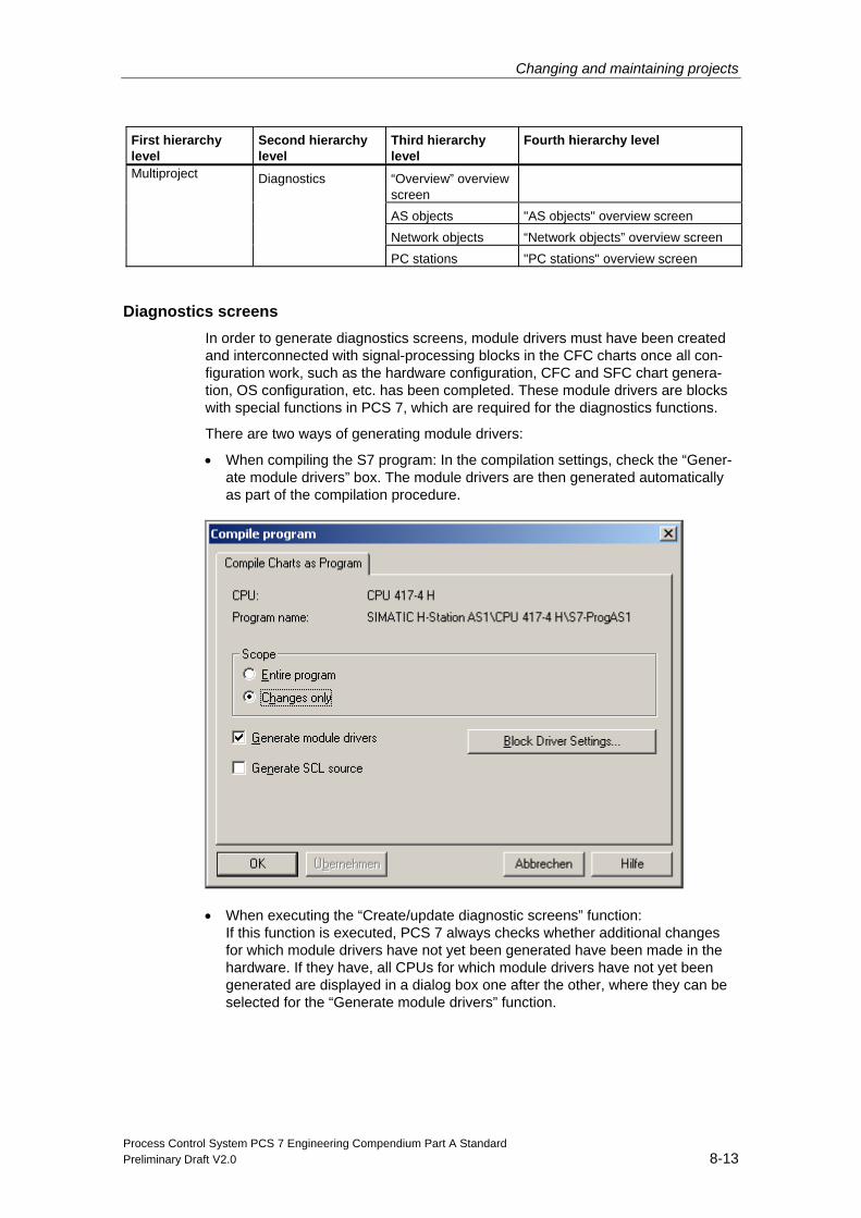
Changing and maintaining projects
Process Control System PCS 7 Engineering Compendium Part A Standard Preliminary Draft V2.0 8-13
First hierarchy level
Second hierarchy level
Third hierarchy level
Fourth hierarchy level
“Overview” overview screen
AS objects "AS objects" overview screen Network objects “Network objects” overview screen
Multiproject
Diagnostics
PC stations "PC stations" overview screen
Diagnostics screens In order to generate diagnostics screens, module drivers must have been created and interconnected with signal-processing blocks in the CFC charts once all con-figuration work, such as the hardware configuration, CFC and SFC chart genera-tion, OS configuration, etc. has been completed. These module drivers are blocks with special functions in PCS 7, which are required for the diagnostics functions.
There are two ways of generating module drivers:
• When compiling the S7 program: In the compilation settings, check the “Gener-ate module drivers” box. The module drivers are then generated automatically as part of the compilation procedure.
• When executing the “Create/update diagnostic screens” function: If this function is executed, PCS 7 always checks whether additional changes for which module drivers have not yet been generated have been made in the hardware. If they have, all CPUs for which module drivers have not yet been generated are displayed in a dialog box one after the other, where they can be selected for the “Generate module drivers” function.
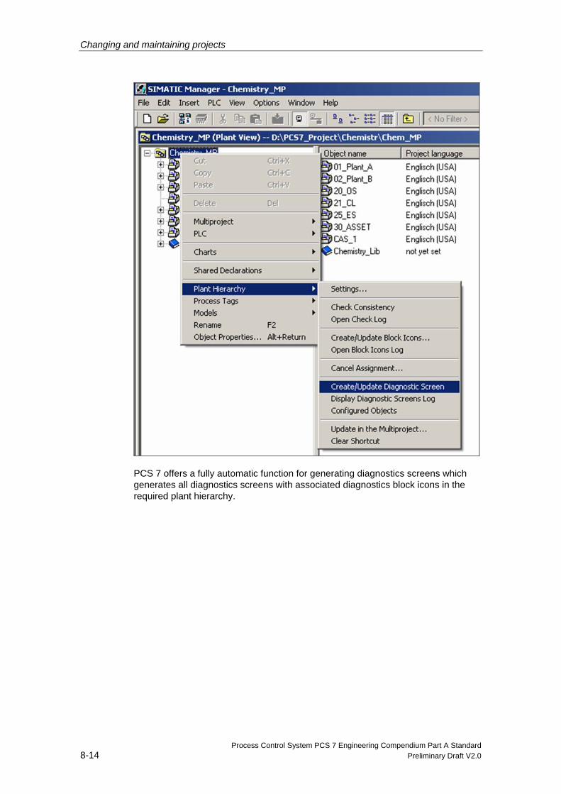
Changing and maintaining projects
Process Control System PCS 7 Engineering Compendium Part A Standard 8-14 Preliminary Draft V2.0
PCS 7 offers a fully automatic function for generating diagnostics screens which generates all diagnostics screens with associated diagnostics block icons in the required plant hierarchy.
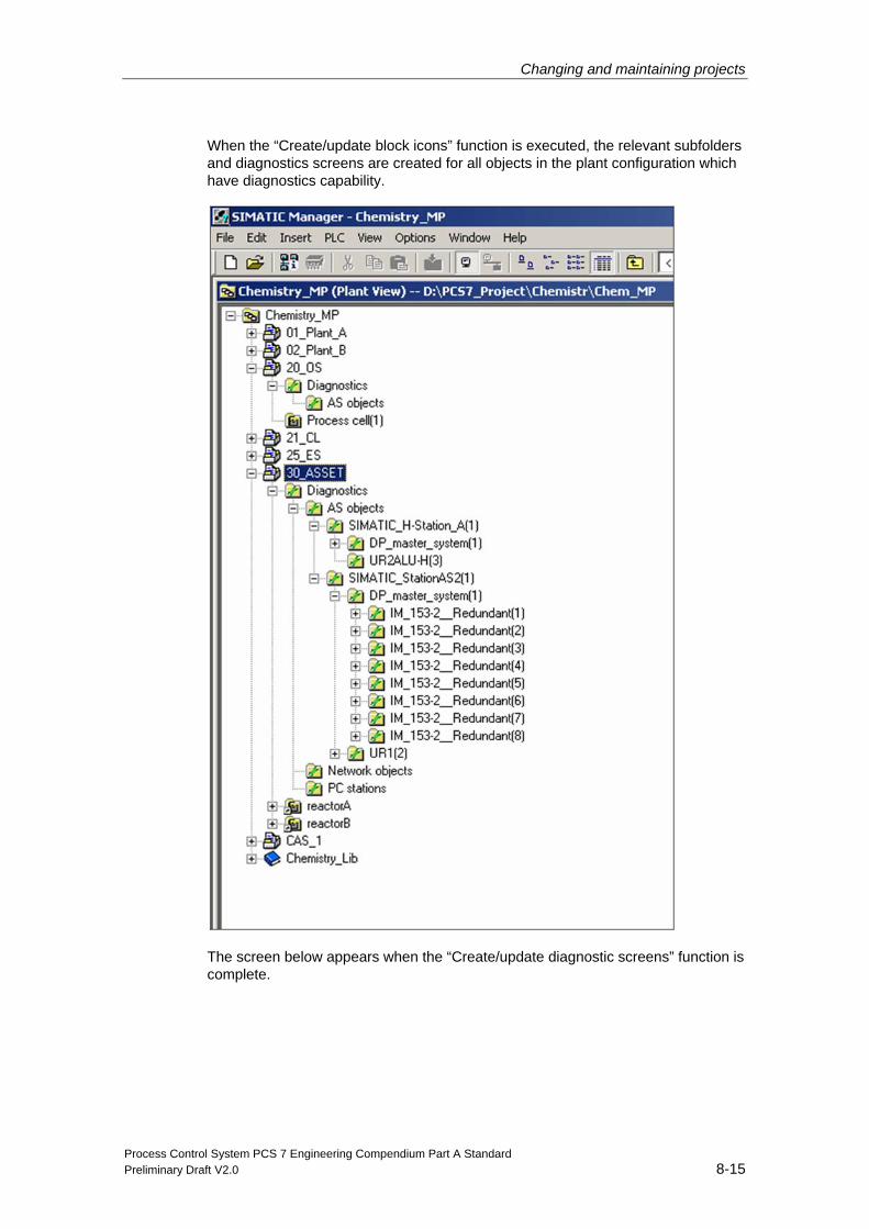
Changing and maintaining projects
Process Control System PCS 7 Engineering Compendium Part A Standard Preliminary Draft V2.0 8-15
When the “Create/update block icons” function is executed, the relevant subfolders and diagnostics screens are created for all objects in the plant configuration which have diagnostics capability.
The screen below appears when the “Create/update diagnostic screens” function is complete.
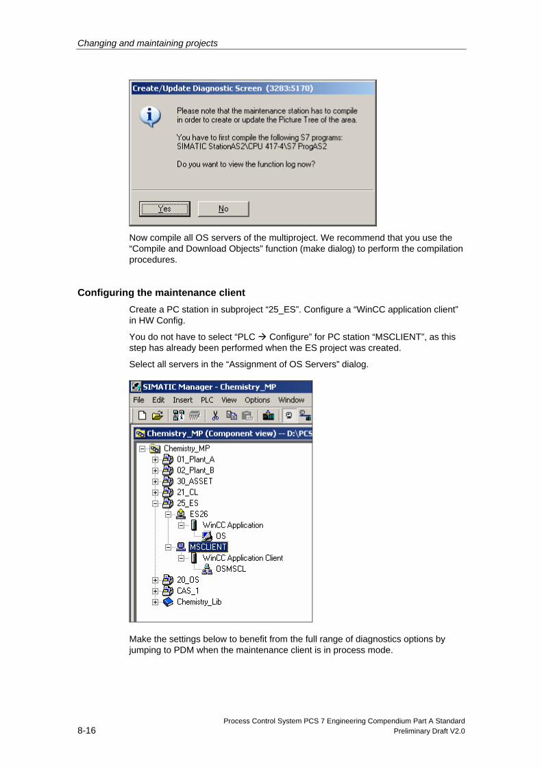
Changing and maintaining projects
Process Control System PCS 7 Engineering Compendium Part A Standard 8-16 Preliminary Draft V2.0
Now compile all OS servers of the multiproject. We recommend that you use the “Compile and Download Objects" function (make dialog) to perform the compilation procedures.
Configuring the maintenance client Create a PC station in subproject “25_ES”. Configure a “WinCC application client” in HW Config.
You do not have to select “PLC Configure” for PC station “MSCLIENT”, as this step has already been performed when the ES project was created.
Select all servers in the “Assignment of OS Servers” dialog.
Make the settings below to benefit from the full range of diagnostics options by jumping to PDM when the maintenance client is in process mode.
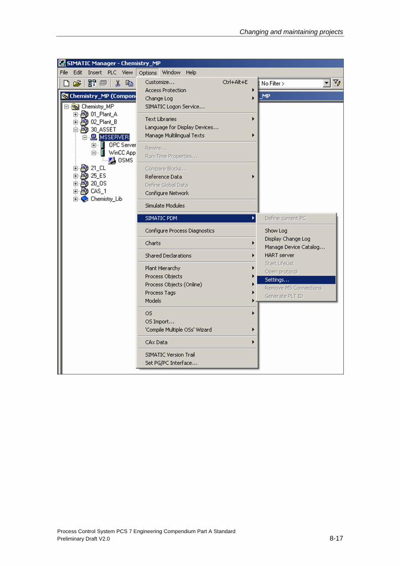
Changing and maintaining projects
Process Control System PCS 7 Engineering Compendium Part A Standard Preliminary Draft V2.0 8-17
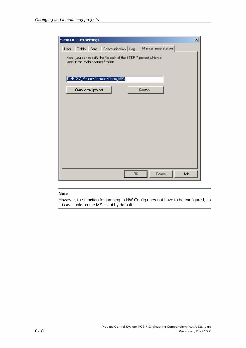
Changing and maintaining projects
Process Control System PCS 7 Engineering Compendium Part A Standard 8-18 Preliminary Draft V2.0
Note However, the function for jumping to HW Config does not have to be configured, as it is available on the MS client by default.
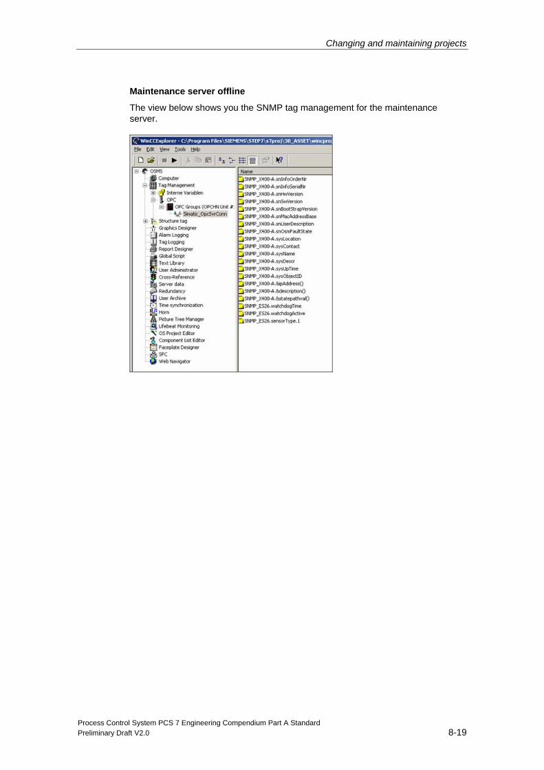
Changing and maintaining projects
Process Control System PCS 7 Engineering Compendium Part A Standard Preliminary Draft V2.0 8-19
Maintenance server offline
The view below shows you the SNMP tag management for the maintenance server.
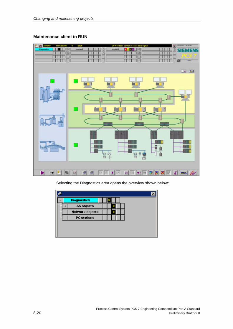
Changing and maintaining projects
Process Control System PCS 7 Engineering Compendium Part A Standard 8-20 Preliminary Draft V2.0
Maintenance client in RUN
Selecting the Diagnostics area opens the overview shown below:
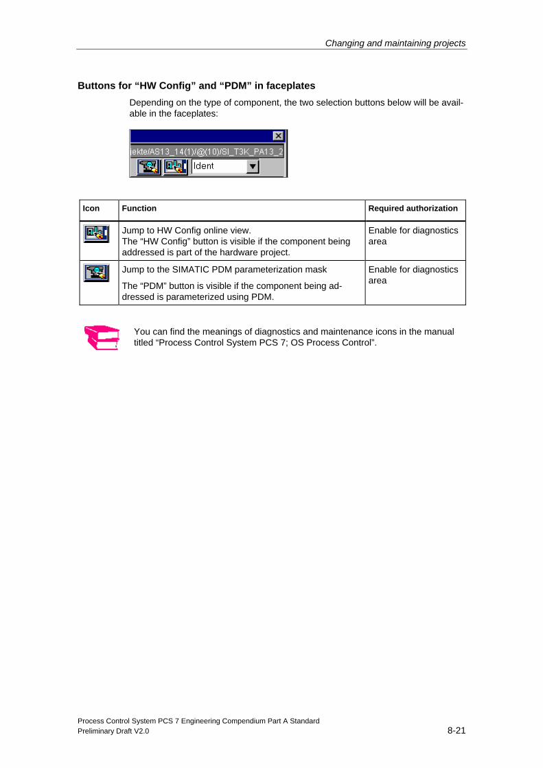
Changing and maintaining projects
Process Control System PCS 7 Engineering Compendium Part A Standard Preliminary Draft V2.0 8-21
Buttons for “HW Config” and “PDM” in faceplates Depending on the type of component, the two selection buttons below will be avail-able in the faceplates:
Icon Function Required authorization
Jump to HW Config online view. The “HW Config” button is visible if the component being addressed is part of the hardware project.
Enable for diagnostics area
Jump to the SIMATIC PDM parameterization mask
The “PDM” button is visible if the component being ad-dressed is parameterized using PDM.
Enable for diagnostics area
You can find the meanings of diagnostics and maintenance icons in the manual titled “Process Control System PCS 7; OS Process Control”.