Embed Size (px)
Citation preview
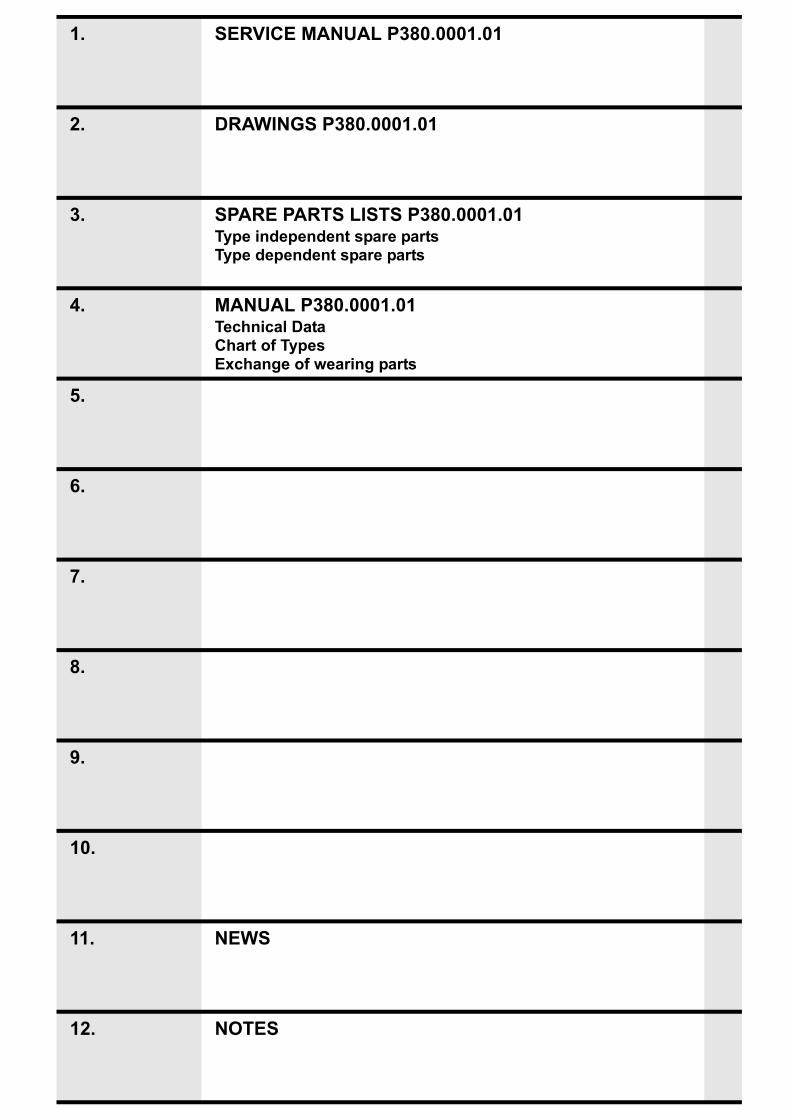
1. SERVICE MANUAL P380.0001.01
2. DRAWINGS P380.0001.01
3. SPARE PARTS LISTS P380.0001.01Type independent spare partsType dependent spare parts
4. MANUAL P380.0001.01Technical DataChart of TypesExchange of wearing parts
5.
6.
7.
8.
9.
10.
11. NEWS
12. NOTES


SERVICE MANUAL
PNEUMATIC PLASTICSTRAPPING TOOL
MODEL P380
P380
.000
1.01
.en.
fm/M
AS/
© 0
5.12
Manual for authorized dealers and service points

1-2
INDEX PAGE
1.1 TECHNICAL DETAILS 1-31.1.1 Air supply . . . . . . . . . . . . . . . . . . . . . . . . . . . . . . . . . . . . . . . . . . . . . . . . . . . . 1-31.1.2 Pneumatic schematic . . . . . . . . . . . . . . . . . . . . . . . . . . . . . . . . . . . . . . . . . . . 1-41.1.3 Functional description . . . . . . . . . . . . . . . . . . . . . . . . . . . . . . . . . . . . . . . . . . . 1-41.1.4 Details of the pneumatic control system . . . . . . . . . . . . . . . . . . . . . . . . . . . . . 1-5
1.2 CONVERSION PARTS 1-7
1.3 PERIODIC MAINTENANCE AND CONTROL 1-81.3.1 Procedure . . . . . . . . . . . . . . . . . . . . . . . . . . . . . . . . . . . . . . . . . . . . . . . . . . . . 1-81.3.2 Troubleshooting. . . . . . . . . . . . . . . . . . . . . . . . . . . . . . . . . . . . . . . . . . . . . . . . 1-91.3.3 Checklist . . . . . . . . . . . . . . . . . . . . . . . . . . . . . . . . . . . . . . . . . . . . . . . . . . . . 1-101.3.4 Glueing rules . . . . . . . . . . . . . . . . . . . . . . . . . . . . . . . . . . . . . . . . . . . . . . . . . 1-111.3.5 Lubrication rules . . . . . . . . . . . . . . . . . . . . . . . . . . . . . . . . . . . . . . . . . . . . . . 1-121.3.6 Assembly information . . . . . . . . . . . . . . . . . . . . . . . . . . . . . . . . . . . . . . . . . . 1-12
1.4 RECOMMENDED SPARE PARTS 1-16
1.5 ACCESSORY TOOLS 1-171.5.1 Use of accessory tools . . . . . . . . . . . . . . . . . . . . . . . . . . . . . . . . . . . . . . . . . 1-18
1.6 ORDERING SPARE PARTS 1-261.6.1 Ordering manuals . . . . . . . . . . . . . . . . . . . . . . . . . . . . . . . . . . . . . . . . . . . . . 1-261.6.2 Ordering address. . . . . . . . . . . . . . . . . . . . . . . . . . . . . . . . . . . . . . . . . . . . . . 1-261.6.3 Finding out of the tool type (item number), the serial number and
the version number:. . . . . . . . . . . . . . . . . . . . . . . . . . . . . . . . . . . . . . . . . . . . 1-27
5.7 SERVICE ADDRESS 1-27
1-3
Only trained and instructed personnel is authorized to perform servicing and maintenance works!
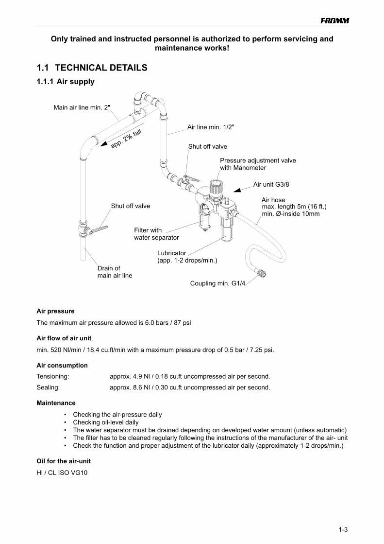
1.1 TECHNICAL DETAILS1.1.1 Air supply
Air pressure
The maximum air pressure allowed is 6.0 bars / 87 psi
Air flow of air unit
min. 520 Nl/min / 18.4 cu.ft/min with a maximum pressure drop of 0.5 bar / 7.25 psi.
Air consumptionTensioning: approx. 4.9 Nl / 0.18 cu.ft uncompressed air per second.
Sealing: approx. 8.6 Nl / 0.30 cu.ft uncompressed air per second.
Maintenance
• Checking the air-pressure daily• Checking oil-level daily• The water separator must be drained depending on developed water amount (unless automatic)• The filter has to be cleaned regularly following the instructions of the manufacturer of the air- unit• Check the function and proper adjustment of the lubricator daily (approximately 1-2 drops/min.)
Oil for the air-unit
Hl / CL ISO VG10
Shut off valve
Drain ofmain air line
Lubricator (app. 1-2 drops/min.)
Filter with
app. 2% fall
Shut off valve
Pressure adjustment valvewith Manometer
water separator
Coupling min. G1/4
Main air line min. 2"
Air line min. 1/2"
Air unit G3/8
max. length 5m (16 ft.)min. Ø-inside 10mm
Air hose

1-4
1.1.2 Pneumatic schematic
1.1.3 Functional descriptionZero position
• When connecting the tool to the air line, compressed air flows through the Turn off valve (13) to the Tensioner valve (1) and to the Welding signal valve (12).
• Directly from the main connector P compressed air is lead also to the Welding valve (5), to the Welding motor valve (7), to the Welding turn off valve (15) and to the Cool down signal valve (14).
Actuating the Valve lever for tensioning (a)• The Turn off valve (13) is held by spring force in the home position and is therefore opened.• By persistent pressing of the Valve lever for tensioning (a) the Tensioner valve (1) is held in open
position. The compressed air flows through the Tension force control valve (2) (with adjustment knob) to the tensioning motor (3), powers the motor and is leaving it in the decompressed status through the Exhaust silencer (4).
• If a certain back up pressure of the Tensioning motor (3), determined by the adjustment knob, is reached, the Tension force control valve (2) throttles the air supply to the Tensioning motor (3). This allows an adjustment of the tensioning force.
• The Valve lever for tensioning can be released now. The tension force is held by the needle free wheeling N3.4509.
Actuating the Valve lever for welding (b)• The valve lever for welding (b) is pressed until the lower stop and immediately released. This is
starting a sequence of automatically run down processes.• The compressed air coming from connection P flows through the Turn off valve (13), flows
through the Welding signal valve (12) and is switching the Welding valve (5). This is going into self locking mode.
P
1
2
34
56
5
1
2
3
12
1
2
3
4
13
1
2
1
1
2
3
4
2
1
2
3
4
1
3
2
48
1
2
91
3
2
4
10
1
2
34
14
1
2
3
4
7
1
2
34
15
a
b
1
2
11 16
6
4 1 Tensioner valve2 Tension force control valve3 Tensioning motor4 Exhaust silencer5 Welding valve6 Throttle 0.67 Welding motor valve8 Welding time valve9 Welding motor10 Cooling time valve11 Welding cylinder12 Welding signal valve13 Turn off valve14 Cooling signal valve15 Welding turn off valve16 Cylinder reverse stop
a Tensioner valve leverb Welding valve lever
1-5
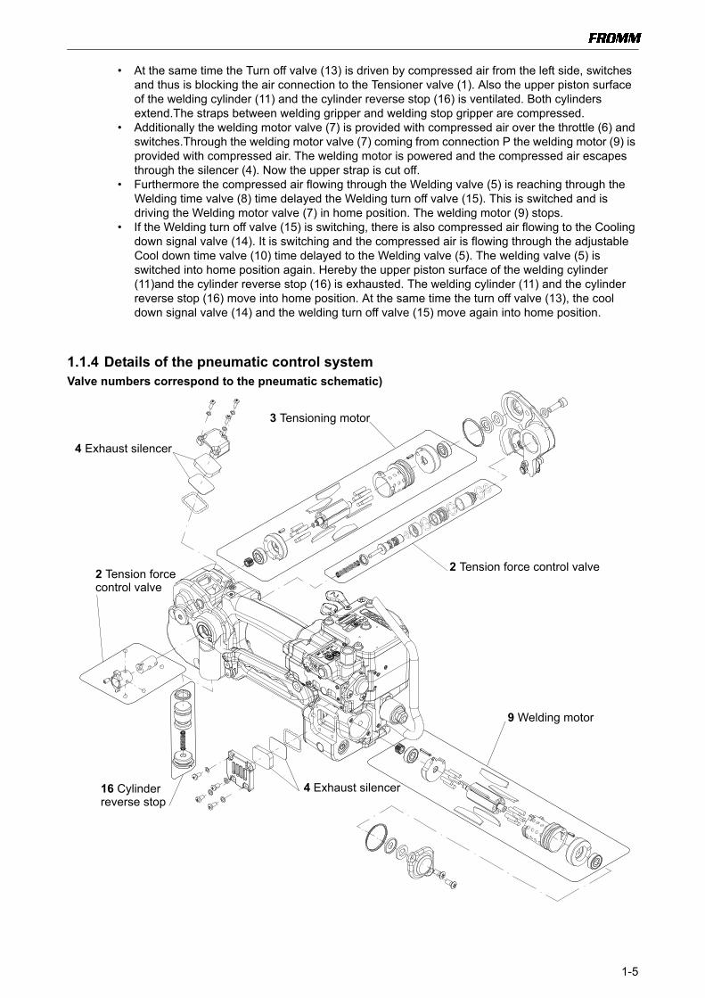
• At the same time the Turn off valve (13) is driven by compressed air from the left side, switches and thus is blocking the air connection to the Tensioner valve (1). Also the upper piston surface of the welding cylinder (11) and the cylinder reverse stop (16) is ventilated. Both cylinders extend.The straps between welding gripper and welding stop gripper are compressed.
• Additionally the welding motor valve (7) is provided with compressed air over the throttle (6) and switches.Through the welding motor valve (7) coming from connection P the welding motor (9) is provided with compressed air. The welding motor is powered and the compressed air escapes through the silencer (4). Now the upper strap is cut off.
• Furthermore the compressed air flowing through the Welding valve (5) is reaching through the Welding time valve (8) time delayed the Welding turn off valve (15). This is switched and is driving the Welding motor valve (7) in home position. The welding motor (9) stops.
• If the Welding turn off valve (15) is switching, there is also compressed air flowing to the Cooling down signal valve (14). It is switching and the compressed air is flowing through the adjustable Cool down time valve (10) time delayed to the Welding valve (5). The welding valve (5) is switched into home position again. Hereby the upper piston surface of the welding cylinder (11)and the cylinder reverse stop (16) is exhausted. The welding cylinder (11) and the cylinder reverse stop (16) move into home position. At the same time the turn off valve (13), the cool down signal valve (14) and the welding turn off valve (15) move again into home position.
1.1.4 Details of the pneumatic control systemValve numbers correspond to the pneumatic schematic)
3 Tensioning motor
9 Welding motor
2 Tension force control valve2 Tension force
16 Cylinder
4 Exhaust silencer
control valve
4 Exhaust silencerreverse stop

1-6
a Valve lever
b Valve lever for welding
1 Tensioner valve
12 Welding signal valve
8 Welding time valve
13 Turn off valve 10 Cool down time valve
14 Cool down
15 Welding
5 Welding valve
6 Throttle 0.6
7 Welding motor valve
for tensioning
signal valve
turn off valve
1-7
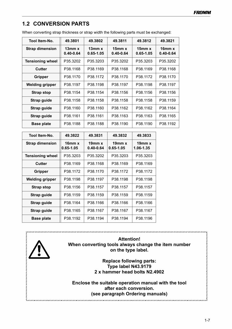
1.2 CONVERSION PARTSWhen converting strap thickness or strap width the following parts must be exchanged:
Tool Item-No. 49.3801 49.3802 49.3811 49.3812 49.3821
Strap dimension 13mm x0.40-0.64
13mm x 0.65-1.05
15mm x0.40-0.64
15mm x 0.65-1.05
16mm x0.40-0.64
Tensioning wheel P35.3202 P35.3203 P35.3202 P35.3203 P35.3202
Cutter P38.1168 P38.1169 P38.1168 P38.1169 P38.1168
Gripper P38.1170 P38.1172 P38.1170 P38.1172 P38.1170
Welding gripper P38.1197 P38.1198 P38.1197 P38.1198 P38.1197
Strap stop P38.1154 P38.1154 P38.1156 P38.1156 P38.1156
Strap guide P38.1158 P38.1158 P38.1158 P38.1158 P38.1159
Strap guide P38.1160 P38.1160 P38.1162 P38.1162 P38.1164
Strap guide P38.1161 P38.1161 P38.1163 P38.1163 P38.1165
Base plate P38.1188 P38.1188 P38.1190 P38.1190 P38.1192
Tool Item-No. 49.3822 49.3831 49.3832 49.3833
Strap dimension 16mm x 0.65-1.05
19mm x0.40-0.64
19mm x 0.65-1.05
19mm x 1.06-1.35
Tensioning wheel P35.3203 P35.3202 P35.3203 P35.3203
Cutter P38.1169 P38.1168 P38.1169 P38.1169
Gripper P38.1172 P38.1170 P38.1172 P38.1172
Welding gripper P38.1198 P38.1197 P38.1198 P38.1198
Strap stop P38.1156 P38.1157 P38.1157 P38.1157
Strap guide P38.1159 P38.1159 P38.1159 P38.1159
Strap guide P38.1164 P38.1166 P38.1166 P38.1166
Strap guide P38.1165 P38.1167 P38.1167 P38.1167
Base plate P38.1192 P38.1194 P38.1194 P38.1196
Attention!When converting tools always change the item number
on the type label.
Replace following parts:Type label N43.9179
2 x hammer head bolts N2.4902
Enclose the suitable operation manual with the tool after each conversion.
(see paragraph Ordering manuals)
1-8
1.3 PERIODIC MAINTENANCE AND CONTROLCarry out 12- months cycles doing one shift work. Doing multiple shift work respectively more often.
1.3.1 Procedure
Before using check tool for following possible faults:
• Visual test of the tool for loose, lost or damaged parts
• Clean all dirty parts of the tool, especially strap abrasion in the tensioning or the welding unit by using compressed air. (Never use any hard tools like a wire brush or a screw driver for cleaning)
• Condition of the tensioning wheel, the welding grippers and the tensioning grippers
Connect tool to the air supply and perform some test strappings.Check the following:
• Tightness of the pneumatic system
• Strap guidance
• Strap take up and strap tensioning
• Tensioning force adjustment minimal and maximal (see operation manual P380)
• Cutting of the upper strap
• Welding time adjustment (see operation manual P380)
• Seal quality (see operation manual P380)
Proceed according to paragraph „Troubleshooting“after a fault appears.
Attention!Before maintenance always remove the tool from the compressed air
supply.
For exchange of wearing parts see operation manual P380.
Never use water or solvents for cleaning the tool.

1-9
1.3.2 Troubleshooting
A sufficient compressed air supply and the use of the tool’s specific strap should be guaranteed before each tool repair.
SYMPTOM CAUSE REMEDY
Tool doesn’t tension, Tensioning motor runs
The tensioning wheel is packed with strap residue or is worn and mills on
the strap
Clean tensioning wheel with compressed air or replace it
Wrong tensioning wheel or tensioning wheel is assembled reversed
Correct assembling or use the correct tensioning wheel.
Grippers are dirty, worn or wrongly assembled
Replace grippers, clean them with compressed air or assemble correctly
Gearing parts from the tensioning gear are defective
Check tensioning gear and replace defect parts
Return stop unlocked Check piston
Tensioning motor doesn’t run
Tensioning motor defective Check component parts and replace damaged ones
Tensioning gear defective Check component parts and replace damaged ones
Pneumatic control system is defective Check component parts and replace damaged ones
Needle free wheeling assembled reversed
Assemble correctly
Tensioning wheel turns back immediately after the
tensioning cycle
Defective needle free wheeling N3.4509
Überprüfen und gegebenenfalls ersetzen
Tool doesn’t weld, welding motor runs
Welding gripper is dirty or worn Clean and check welding gripper and replace damaged one
Welding stop gripper is dirty or worn Clean and check welding stop gripper and replace damaged one
Pinion P32.1023 lose at the motor or welding eccentric, resp. The journal at
the welding eccentric is broken off.
Check component parts and replace damaged ones
Welding piston P38.0101 not down Check component parts and replace damaged ones
Welding motor doesn’t run Welding motor defective Check component parts and replace damaged ones
Welding mechanism defective Check component parts and replace damaged ones
Pneumatic control system is defective Check component parts and replace damaged ones
Gear noise Tensioning or welding gear is worn Check component parts and replace damaged ones

1-10
1.3.3 ChecklistCarry out several test strappings and check the following items:
• Connect the tool to the compressed air supply and check if air escapes
• Insertion of the strap
• Strap guidance
• Strap take up and strap tension
• Tension force adjustment minimal and maximal (see operation manual P380)
• Cutting of the upper strap
• Welding time adjustment (see operation manual P380)
• Seal quality (see operation manual P380)
• Type label
Welding motor does not stop
Turn off valve or welding motor valve jam, resp. the welding time valve is
blocked.
Check and clean parts, exchange damaged parts
Diameter of the air supply hose is too small.
Install air supply hose with a minimum inner diameter of 10mm
Not enough air volume Take care that there is enough air volume
(see paragraph 1.1.1 Air supply)
Tool badly cuts the strap or doesn’t cut at all
Cutter is worn or damaged Replace cutter
Welding gripper is worn Replace welding gripper
Welding time too short Change adjustment(see operation manual P380)
Welding time not adjustable
Welding time valve dirty or damaged Clean and check component parts and replace damaged ones
Tensioning force not adjustable
Tension force control valve dirty or damaged
Clean and check component parts and replace damaged ones
SYMPTOM CAUSE REMEDY

1-11
1.3.4 Glueing rules
Following parts have to be glued with LOCTITE 603:
The screws N1.2112 have to be glued additionally in the planetary gear stage P35.0130 using LOCTITE 222.Don’t clamp the planet shaft directly on the teeth when loosening or tightening the screws N1.2112.
N21.2101
P35.3103
N2.2145
Planet shaft P35.3103with the parallel pins N2.2145.
Gearing cover P38.1141 withparallel pins N21.2101
P38.1141
Clamp here
P35.0130
N1.2112

1-12
1.3.5 Lubrication rules
• Lubricate the rocker P38.1125 and the bolt P38.1201 in the area of the welding jaw with Klüber Isoflex NBU 15.
• Lubricate the balls N3.1702, ball cage P38.1199 and the running surface of the balls on the welding gripper with Klüber Isoflex Alltime SL2.
Lubrication interval: At each maintenance or after 12 months at the latest.
All movable gear parts have to be lubricated with MOLYKOTE BR 2 PLUS grease.Lubrication interval: At each maintenance or after 12 months at the latest.
All other parts have to be greased according to the explosion drawing.Lubrication interval: At each maintenance or after 12 months at the latest.
1.3.6 Assembly information
Needle free wheeling:Pay attention to the assembling direction of the needle free wheeling N3.4509.The sense of rotation is stamped at the front of the free wheeling.
Seal N6.6122Pay attention to the mounting position of the Seal N6.6122.(see picture)
Grease the parts with Mobilux EP2.
15 X N3.1702
P38.1199
P38.1125
P38.1201
welding gripper
N3.4509
wrong right
N6.6122
P38.1142

1-13
Vane:If the minimum diameters (see drawing) are not reached anymore, the vanes P35.2024 or P35.3108 must be exchanged.
Assembling of the cover P35.3105 on the idler step P35.0130
Observe assembling direction of the cover.The division of the holes is not 3x120°.The cover must be easy to assemble.If the cover is assembled distorted, the gear runs bad.
Elastomer Spring and Thrust Piece:When assembling the end cover P38.1147, pay attention to the assembling direction of the spring P35.2026 and the thrust piece P35.2027. (see drawing)
Thrust piece towards the motor.
Attach parts with grease on the motor cover!
The same assembling position is valid at the welding motor too!
min
. 8.2
mm
min. 43.2 mm
P35.3108
min
. 8.2
mm
min. 37.2 mm
P35.2024
P35.2021P35.3138
118°
121°12
1°
P35.2026
P35.2027

1-14
Exchange of strap guides and strap stopDisassembling:
• For protection of the tooth system from the gripper a piece of plastic strap should be inserted before loosing or tightening the base plate. (therefore lift the handle)
• Unscrew base plate• Disassemble the end cover P38.0119• To extract the strap guides P38.1160/62/64/66 and P38.1161/63/65/67 respectively pull down the
thrust pieces P38.1110 and P38.1111 and swivel them to the side. (Picture 2) The thrust pieces P38.1110 and P38.1111 are arranged in mirror image.
• Extract the strap guides P38.1160/62/64/66 and P38.1161/63/65/67• Unscrew the strap guide P38.1158/59• Disassemble the strap stop P38.1154/56/57
Assembling:• Set the thrust pieces to swivel in position. (Picture 2) • When setting in the strap guides P38.1154/56/57 push them in to the level of the welding gripper.• Swivel back the thrust pieces• Release the strap guide and check the function. (Press in and release the strap guide 2 or 3
times)• Assembling of strap stop P38.1154/56/57 and strap guide P38.1158/59 in opposite order.• When assembling the strap guide P38.1158/59 pay attention to the width of the strap.
The number of the used strap width has to show to the inside.
P38.1160/62/64/66
P38.1161/63/65/67
P38.1154/56/57
P38.1158/59
N12.1113
N1.6247
N1.6503
N1.1168
N1.1132
N11.1119
N1.6237
N1.6407
N1.1328
P38.0119
Picture 1
Gripper
Base plate
1-15
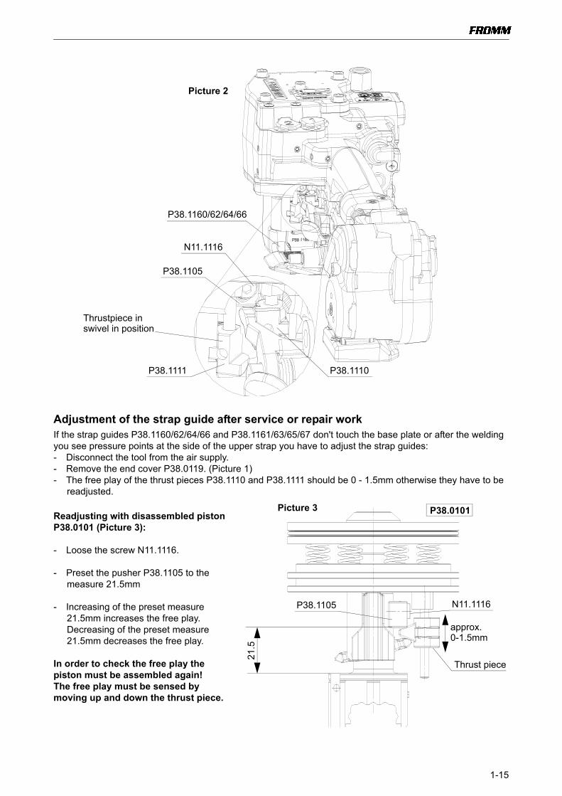
Adjustment of the strap guide after service or repair workIf the strap guides P38.1160/62/64/66 and P38.1161/63/65/67 don't touch the base plate or after the welding you see pressure points at the side of the upper strap you have to adjust the strap guides:- Disconnect the tool from the air supply.- Remove the end cover P38.0119. (Picture 1)- The free play of the thrust pieces P38.1110 and P38.1111 should be 0 - 1.5mm otherwise they have to be
readjusted.
Readjusting with disassembled piston P38.0101 (Picture 3):
- Loose the screw N11.1116.
- Preset the pusher P38.1105 to the measure 21.5mm
- Increasing of the preset measure 21.5mm increases the free play. Decreasing of the preset measure 21.5mm decreases the free play.
In order to check the free play the piston must be assembled again!The free play must be sensed by moving up and down the thrust piece.
Picture 2
N11.1116
P38.1105
P38.1110P38.1111
Thrustpiece in
P38.1160/62/64/66
swivel in position
21.5
P38.1105 N11.1116
Thrust piece
P38.0101Picture 3
approx. 0-1.5mm

1-16
Assembling of the valve P38.0103Pay attention to the assembling position of the spring ring N2.1613. The grinded side must show to the outside.
1.4 RECOMMENDED SPARE PARTSFollowing spare parts are recommended for stock keeping:
*= wearing partsStock only parts from tools that are in sale.
Item-No. Description Pieces per toolN1.1168 Screw 2
N1.1306 Screw 2
N1.1807 Raised ctrs. head screw 4
N1.1808 Raised ctrs. head screw 3
N1.1813 Raised ctrs. head screw 3
N1.1820 Raised ctrs. head screw 2
N1.6407 Tooth washer 4
N1.6503 Safety washer 2
N2.1121 Security ring 2
N2.1613 Spring ring 2
N3.1702 Ball 21
N5.2702 Cover 2
N6.6233 O-Ring 3
N6.6262 O-Ring 1
N6.6264 O-Ring 1
N6.6268 O-Ring 1
P35.2024* Vane 5
P35.3108* Vane 5
P35.3202* Tensioning Wheel (for 0.40 - 0.64 mm Strap thickness) 1
P35.3203* Tensioning Wheel (for 0.65 - 1.35 mm Strap thickness) 1
P38.1151* Slide jaw 1
P38.1168* Cutter (for 0.40 - 0.64 mm Strap thickness) 1
P38.1169* Cutter (for 0.65 - 1.35 mm Strap thickness) 1
P38.1170* Gripper (for 0.40 - 0.64 mm Strap thickness) 1
P38.1172* Gripper (for 0.65 - 1.35 mm Strap thickness) 1
P38.1187* Welding stop gripper 1
P38.1197* Welding gripper (for 0.40 - 0.64 mm Strap thickness) 1
P38.1198* Welding gripper (for 0.65 - 1.35 mm Strap thickness) 1
P38.1199 Ball cage 1
P38.1201 Bolt 1
N2.1613N2.1613
outside grinded outside grinded

1-17
1.5 ACCESSORY TOOLS
Partly some of these tools are already used for other models.
Item number Description Application
N71.3247 Press in and press out pressure pad N3.1157/P35.3103
N71.3264 Press in and press out arbor N3.1157/P35.3103
N71.3237 Press in and press out arbor N3.1159/P32.1037 and N3.2356/P38.1147
N71.3238 Press in and press out pressure pad N3.1159/P32.1037
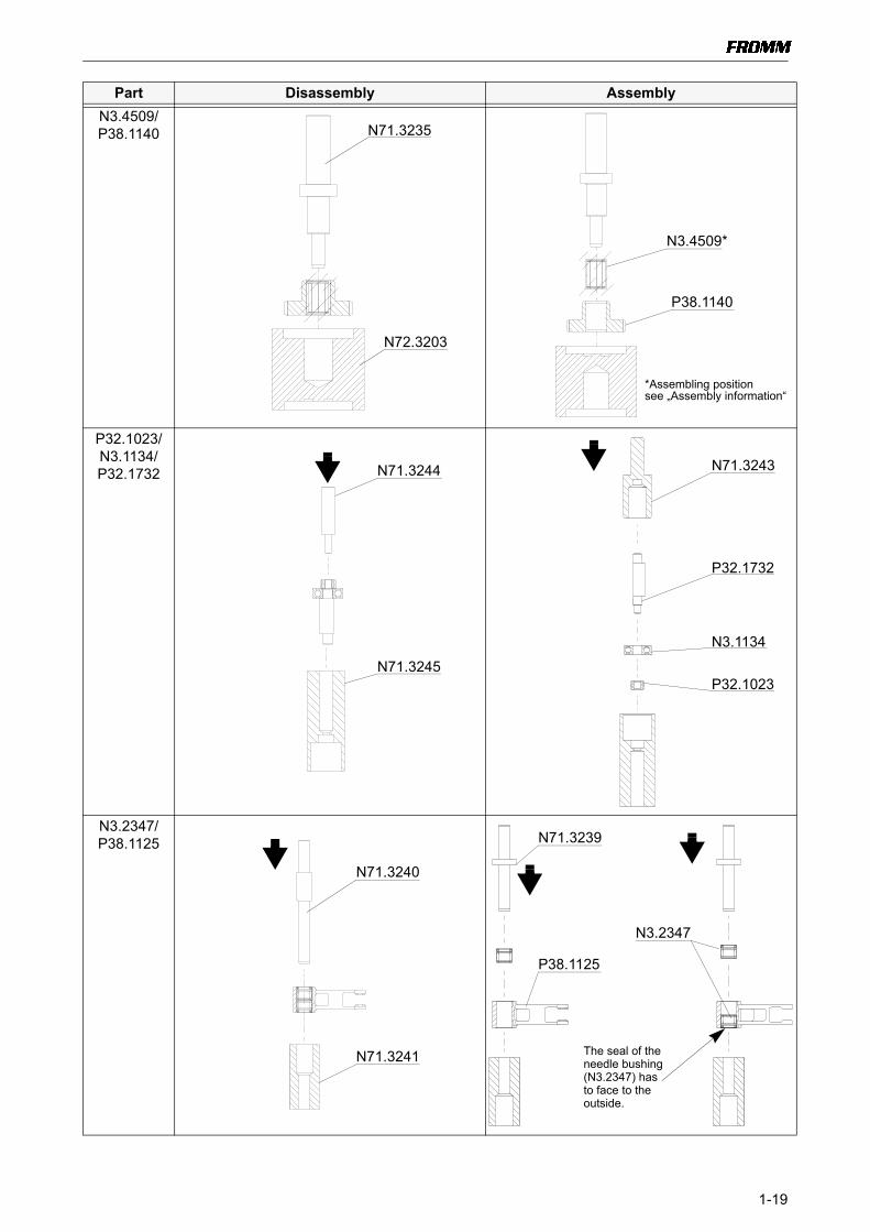
N71.3235 Press in and press out arbor N3.4509/P38.1140
N72.3203 Press in and press out pressure pad N3.4509/P38.1140
N71.3244 Press out arbor N3.1134, P32.1023/P32.1732
N71.3245 Pressure pad N3.1134, P32.1023/P32.1732 and N3.2356/P38.1147
N71.3240 Press out arbor N3.2347/P38.1125
N71.3241 Press in and press out pressure pad N3.2347/P38.1125
N71.3266 Press out arbor N3.2356/P38.1147
N71.3280 Press out pressure pad P32.1023/P35.0140
N71.3255 Sleeve P32.1023/P35.0140
N71.3254 Press on arbor P32.1023/P35.0140
N71.3281 Press on pressure pad P32.1023/P35.0140
N71.3277 Thrust piece P35.3138 resp. P35.2021/P35.2023, N3.1174
N71.3276 Pressure pad P35.3138 resp. P35.2021/P35.2023, N3.1174
N71.3274 Hook P35.2005, P35.3129, P35.3157, P35.3145, P35.2059/P38.1112
N71.3299 Hook P35.3114/P38.1112
N72.3201 Spring clamp P38.1104/P38.0101

1-18
1.5.1Use of accessory tools Accessory tools should only be used with the suitable arbor press N7.5108 in order to avoid a tilt of the pressed in parts. Additional a retainer (N7.3215) is necessary.
Part Disassembly AssemblyN3.1157/P35.3103
N3.1159/P32.1037
N7.5108
N7.3215
N71.3264
N71.3247
N3.1157
P35.3103
N71.3237
N71.3238
N3.1159
P32.1037
1-19
N3.4509/P38.1140
P32.1023/N3.1134/P32.1732
N3.2347/P38.1125
Part Disassembly Assembly
A
A
N71.3235
N72.3203
N3.4509*
P38.1140
*Assembling positionsee „Assembly information“
N71.3244
N71.3245
N71.3243
P32.1732
N3.1134
P32.1023
N71.3240
N71.3241
N71.3239
P38.1125
N3.2347
The seal of theneedle bushing(N3.2347) has to face to theoutside.

1-20
N3.2356/P38.1147
P32.1023/P35.0140
Part Disassembly Assembly
N71.3266
N71.3245 P38.1147
N3.2356
N71.3237
Picture 1
Picture 2
P32.1023
P35.0140
N71.3254
N71.3281
N71.3244
N71.3280
N71.3255

1-21
Part Disassembly Assembly
P35.2023/N3.1174/P35.3138
resp.P35.2021
Commercially available Puller.
N71.3277
P35.2023
N3.1174
N71.3276
0.03
mm
P35.3138 P35.2021
The distance between rotor (P35.3138resp. P35.2021) and end plate (P35.2023) should be 0.03 mm

1-22
Proceeding for valve disassembling:• Press clip together and insert it into the hole, until it snaps into the shown position• Insert coupler pull out exhaust ring
Attention! When disassembling the valves don’t damage the ball seat.
Part Disassembly
P35.2005 resp.
P35.3129/P38.1112
�
N71.3274
Coupler
Clip
Hook in here
P35.2005
P35.3129
Picture 2
Picture 1
Ball seat

1-23
P35.3157/P38.1112
P35.3145/P38.1112
Part Disassembly
�
N71.3274
P35.3157
Hook in here
�
N71.3274
P35.3145
Hook in here

1-24
P35.2059/P38.1112
P35.3114/P38.1112
Part Disassembly
N71.3274
P35.2059
Hook in here
�
N71.3299 P35.3114
Hook in here
1-25
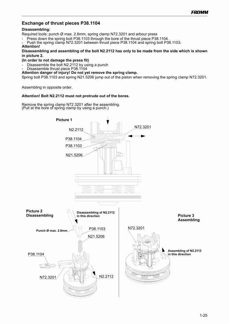
Exchange of thrust pieces P38.1104Disassembling: Required tools: punch Ø max. 2.8mm, spring clamp N72.3201 and arbour press- Press down the spring bolt P38.1103 through the bore of the thrust piece P38.1104.- Push the spring clamp N72.3201 between thrust piece P38.1104 and spring bolt P38.1103.Attention!Disassembling and assembling of the bolt N2.2112 has only to be made from the side which is shownin picture 2.(In order to not damage the press fit)- Disassemble the bolt N2.2112 by using a punch- Disassemble thrust piece P38.1104Attention danger of injury! Do not yet remove the spring clamp.Spring bolt P38.1103 and spring N21.5206 jump out of the piston when removing the spring clamp N72.3201.
Assembling in opposite order.
Attention! Bolt N2.2112 must not protrude out of the bores.
Remove the spring clamp N72.3201 after the assembling.(Pull at the bore of spring clamp by using a punch.)
P38.1104
N72.3201N2.2112
P38.1103
N21.5206
P38.1104
N72.3201
P38.1103
N21.5206
Picture 1
Picture 3Picture 2
N2.2112
Punch Ø max. 2.8mm
DisassemblingAssembling
N72.3201
Disassembling of N2.2112 in this direction
Assembling of N2.2112 in this direction

1-26
1.6 ORDERING SPARE PARTSOn principle spare part numbers should be taken from the drawings or spare parts lists. Check if the version number of the tool and the spare parts list are the same.Type dependent spare parts should be ordered as follows:
Ordering exampleOrdering a tensioning wheel:
• Take item numbers of the tensioning wheel from drawing (P35.3202/03)• Find out the tool type in which the tensioning wheel should be assembled (e.g. 49.3801)• Find out the item number of the needed tensioning wheel by using the type dependent spare
parts lists (for type 49.3801, it is tensioning wheel P35.3202)
Order as follows if 10 tensioning wheels are needed:P35.3202 Tensioning wheel 10 pcs.
1.6.1 Ordering manualsWhen converting tools make sure that the used manual has still validity.If tools change their item number because of the conversion (see chart of types) the adequate manual must be ordered as follows.
Ordering example: Tool item number: 49.3801Version number: 01Language of the manual: German
The manual order for this tool must look as follows:49380101.deIf the manual is needed in another language replace the shorthand expression "de" (see table).
1.6.2 Ordering addressSpare parts and manuals can be ordered at:
Fromm Holding AG Tel.: +41(0) 41 741 57 41Hinterbergstrasse 26 Fax: +41(0) 41 741 57 60CH-6330 Cham e-mail: [email protected]
de German
en English
fr French
it Italian
fin Finnish
nl Dutch
po Portuguese
se Swedish
sp Spanish
ru Russian
cz Czech
pl Polish

1-27
1.6.3 Finding out of the tool type (item number), the serial number and the version number:
Type label P380
5.7 SERVICE ADDRESSYou will get further assistance and information at:
Fromm System GmbHTechnical customer supportNeulandstr. 10D-77855 AchernGermany
Phone: +49(0)7841 / 62 94-22Fax: +49(0)7841 / 62 94-11
e-mail: [email protected]
4 9 . 3 8 0 10 1 0 0 2 8 4{
Item numberSerial numberVersion number

1-28

2-1P380.0001.01se.z
A1
B C
23
45
6
D
N11
.111
9
N1.
1132
N11
.111
9
N1.
6237
P38.
1186
N4.
1221
P38.
1188
/90/
92/9
4/96
N1.
6503
N1.
6407
7N
1.13
06
N1.
1168
N1.
7111
N2.
2110
N2.
2118
1N
21.5
206
N21
.210
2
N1.
6407
1N
6.62
641
P35.
1207
P38.
1151
N1.
1808
1N
1.71
16
N2.
2138
1P3
8.11
491
N21
.520
4N
2.49
06
N21
.211
9
N1.
5105
P38.
1202
1N
2.56
23
1N
21.5
205
P38.
1101
1P3
5.20
69
N1.
2110
1N
6.62
121P3
5.20
67
1P3
5.20
73
P35.
2068
P38.
0118
P38.
1154
/56/
57
N1.
1328
P38.
0115
N2.
2110
N2.
5843
P38.
0119
P38.
1131
1P3
8.11
32
1P3
8.11
36
P38.
1148
P38.
0109
1P3
8.11
35
P38.
1187
8
Orie
ntat
ion
7 L
octit
e 22
2
6 L
octit
e 60
3
5 K
lübe
r Iso
flex
NBU
15
4 K
lübe
r Iso
flex
Allti
me
SL2
3 M
obil
Velo
cite
No.
6
2 M
olyk
ote
BR 2
plu
s
1 M
obilu
x EP
2
P38.
0116
/17
P38.
1170
/72
1P3
8.11
34
1P3
8.11
33
1P3
8.11
60/6
2/64
/66
1P3
8.11
61/6
3/65
/67
N2.
2166

2-2 P380.0001.
A7
B C
89
1011
12
D
P38.
1203
N1.
6199
N1.
2159
(N6.
3511
)
1N
21.5
201
1N
21.5
201
1P3
5.20
26P3
5.20
27
P35.
2023
N2.
2402
35
x P3
5.20
22
35
x P3
5.20
223
5 x
P35.
3108
P35.
3107
N2.
2403
P35.
3109
N3.
1174
2P3
2.10
23
N1.
1911
N1.
6504
P38.
1128
P38.
1129
P38.
11301
N61
.621
4
N1.
6237
N1.
1114
N2.
2190
2N
1.63
312
P32.
1037
6N
3.11
592
N1.
6331
N5.
2702
N3.
1134
P32.
1732
N3.
1134
2P3
2.10
23
N1.
1807
P38.
1127
N3.
2347
5P3
8.11
25N
3.23
47
N2.
1121
5P3
8.12
01
N2.
1121
415
x N
3.17
02
4P3
8.11
99
N2.
2102
1P3
8.11
03
1N
21.5
206
P38.
1102
P38.
1168
/69
N11
.111
6N
1.64
05N
1.61
15
N2.
2112
P38.
1105
N2.
4409
1N
2.51
99
P38.
1108
1P3
8.11
071
P38.
1109
1P3
8.11
111
P38.
1110
N1.
6228
N1.
1140
N2.
4409
1N
2.51
99
P38.
1108P3
8.11
06
6N
2.21
24
1P3
8.11
07(N
6.35
03)
4P3
8.11
97/9
8
1N
6.62
68
P38.
1124
P38.
1104
8
Orie
ntat
ion
7 L
octit
e 22
2
6 L
octit
e 60
3
5 K
lübe
r Iso
flex
NBU
15
4 K
lübe
r Iso
flex
Allti
me
SL2
3 M
obil
Velo
cite
No.
6
2 M
olyk
ote
BR 2
plu
s
1 M
obilu
x EP
2
P38.
0101
P35.
0140
P38.
0106
P35.
0137
P32.
1731
P38.
0108
P38.
1126
1N
6.62
37
N3.
1174
N1.
1807
P38.
0116
/17
P35.
3138

2-3P380.0001.01se.z
A13
B C
1415
1617
18
D
N1.
3128
1N
3.17
021
P38.
1205
1N
3.17
02
N11
.114
7
N1.
6237
1N
2.52
59
P35.
2038
2P3
2.11
23N
3.11
74P3
8.11
37N
2.24
023
5x P
35.2
022
35x
P35
.202
2
P35.
2020
N2.
2402
P35.
2023
N3.
1174
1N
6.62
37P3
5.20
27
2P3
8.11
392
P35.
3113
2N
3.21
05
P35.
3105
7N
1.21
12
N2.
1610
2P3
5.31
03
6N
2.21
45
2P3
5.31
04
2N
1.63
312
P38.
1140
8N
3.45
091
N6.
6122
1N
2.51
761
P38.
1142
2P3
8.11
44N
2.21
63
P38.
1143
1N
6.62
62
1N
6.62
24N
1.13
06
N2.
3368
1N
6.62
351
P38.
1146
1N
6.62
351N
6.62
351
P35.
2031
1N
6.62
68
2P3
2.17
12
2N
3.21
072
P35.
3201
2P3
5.32
02/0
3
1P3
8.11
50
N1.
6163
N1.
6247
N3.
2356
N12
.111
3
P38.
1158
/59
N1.
1922
P38.
1145
P38.
1129
P38.
1130
1N
6.62
33
1N
61.6
214
N1.
6505
6(N
21.2
101)
N3.
1172
N3.
1178
N3.
1160
N3.
1157
1N
6.62
32
P38.
1147
1N
6.61
63
8
Orie
ntat
ion
7 L
octit
e 22
2
6 L
octit
e 60
3
5 K
lübe
r Iso
flex
NBU
15
4 K
lübe
r Iso
flex
Allti
me
SL2
3 M
obil
Velo
cite
No.
6
2 M
olyk
ote
BR 2
plu
s
1 M
obilu
x EP
2
1P3
5.20
29
1P3
5.20
32
N11
.114
3
P38.
0113
35x
P35
.202
4
P38.
0114
P38.
0110
P38.
0111
P35.
0133
P35.
0132
P35.
0130
P38.
0112
N3.
1172
2P3
5.31
12
P35.
2021
(N2.
4906
)P3
8.11
38
1P3
5.20
26
P38.
0116
/17
P38.
1141

2-4 P380.0001.
A19
B C
2021
2223
24
D1
P35.
3146
1N
61.6
208
1P3
5.31
451
N6.
6117
1P3
5.31
441
N6.
6117
1N
6.62
911
N6.
6117
1P3
5.31
43 1P3
5.31
421
N6.
6291
1P3
8.11
211
N6.
6291
1N
2.51
761
P35.
2046
1N
6.61
211P3
5.20
451N
6.61
211P3
8.11
18
1N
6.61
17
1N
6.61
171P3
5.31
531P3
5.31
521N
2.52
811
N6.
6147
1P3
5.31
491N
6.62
98
1N
6.61
171
P35.
3150
1N
6.61
17
1N
61.6
221
1P3
5.31
57
1P3
5.31
44
1N
6.62
91 1N
6.62
91
1N
6.61
17
1N
6.61
17
1N
6.62
911
P38.
1121
1P3
5.31
51
1N
6.62
11
1N
6.62
11 1N
6.62
11 1N
6.62
11 1N
6.62
111
N6.
6211
1N
6.62
11
1N
2.52
92
1P3
5.31
56
1N
6.61
85
1P3
5.20
55
1P3
8.11
19
1P3
5.20
451
N6.
6121
N11
.117
1N
11.1
171
N1.
6237
N1.
6237
N11
.114
7N
1.62
37
P35.
2065
N6.
5693
1P3
5.31
151
N2.
5291
1N
6.61
211
P35.
3114
1N
6.61
211
N6.
6211
1N
6.62
11
1P3
5.31
141
N6.
6121
1P3
5.31
16
1N
6.62
66
P38.
1114
1N
6.62
11
N2.
2102
1N
6.62
33
1N
6.62
89
5P3
8.11
165
P38.
1117
N1.
1820
P35.
3136
1P3
5.31
33
1N
2.51
521
N6.
6280
1P3
5.31
321
P35.
3130
1P3
5.31
291
N6.
6280
1N
3.17
111
N2.
5219
1N
6.61
171
P35.
2005
1N
3.17
02
P38.
1120
P35.
2059
1N
6.62
69N
2.52
24
3P3
5.20
58
1P3
5.20
57
1N
6.62
69
P38.
1113 N1.
1813
3N
6.61
57
P35.
2060
N2.
1301
1N
6.62
83
P38.
1115
1P3
5.31
55
N1.
1813
N1.
1808
N4.
9159
N2.
4902
N43
.917
9
P38.
0105
N44
.910
4
1N
2.52
801P3
5.31
59
P38.
0102
P38.
0104
1P3
8.11
22
P38.
0105
P38.
1112
P38.
0103
8
8
Orie
ntat
ion
7 L
octit
e 22
2
6 L
octit
e 60
3
5 K
lübe
r Iso
flex
NB
U 1
5
4 K
lübe
r Iso
flex
Allti
me
SL2
3 M
obil
Velo
cite
No.
6
2 M
olyk
ote
BR 2
plu
s
1 M
obilu
x EP
2
P38.
1123
1P3
5.20
43
N2.
1613
N2.
1613
P38.
0116
/17
1P3
5.31
31
N5.
2702N
41.9
127
N41
.912
9
1N
6.62
64
P38.
1207

[ ] = Group * = Wearing parts
3-1
3 SPARE PARTS LIST P380
3.1 Type independent spare parts P380.0001.01
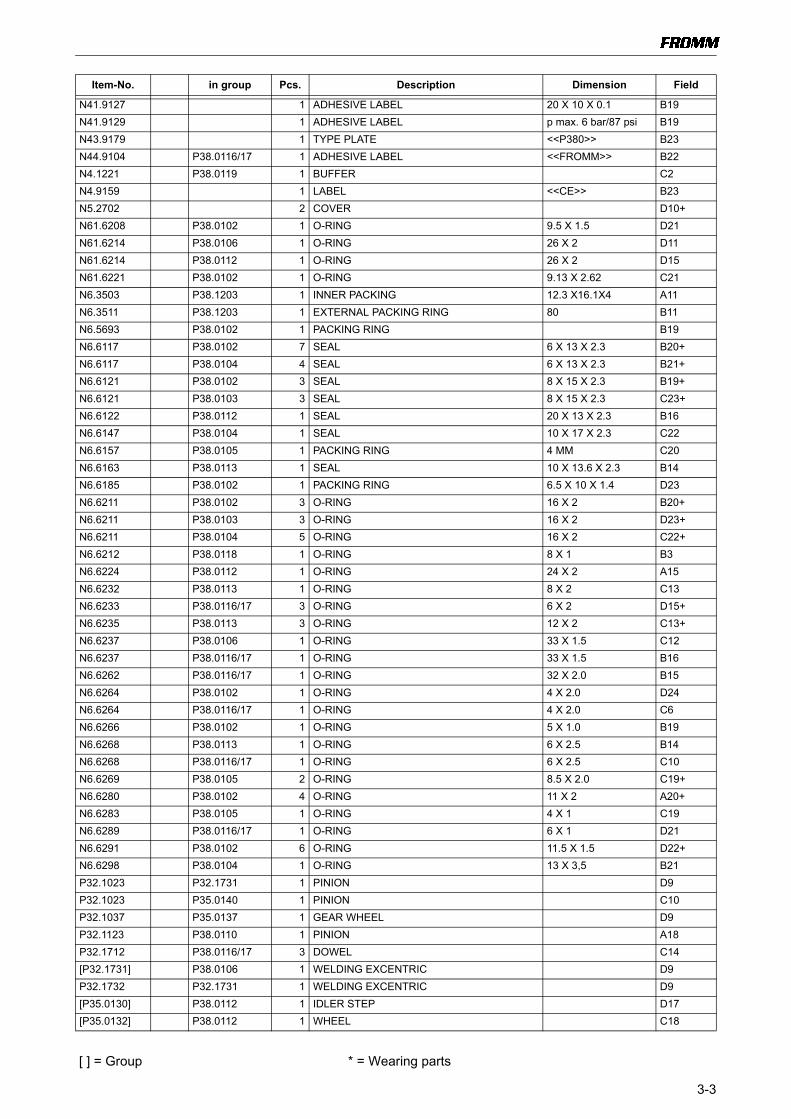
Item-No. in group Pcs. Description Dimension Field
N11.1116 P38.0101 1 SCREW M4 X 12 B8N11.1119 P38.0116/17 2 SCREW M5 X 20 C1+N11.1143 P38.0116/17 1 SCREW M6 X 20 C13N11.1147 P38.0112 3 SCREW M5 X 16 B16N11.1147 P38.0116/17 1 SCREW M5 X 16 A22N11.1171 P38.0116/17 4 SCREW M5 X 80 A21+N12.1113 1 FLAT HEAD SCREW M4 X 25 D13N1.1114 P38.0116/17 1 SCREW M5 X 25 D10N1.1132 P38.0116/17 1 SCREW M5 X 50 C1N1.1140 P38.0101 2 SCREW M4 X 8 A9N1.1168 2 SCREW M5 X 16 D3N1.1306 2 SCREW M3 X 5 D3N1.1306 P38.0112 1 SCREW M3 X 5 A15N1.1328 2 SCREW M3 X 10 C5N1.1807 P38.0106 4 RAISED CTRS. HEAD SCREW M5 X 12 D9+N1.1808 P38.0102 1 RAISED CTRS. HEAD SCREW M4 X 10 D19N1.1808 P38.0116/17 2 RAISED CTRS. HEAD SCREW M4 X 10 B6N1.1813 P38.0102 3 RAISED CTRS. HEAD SCREW M5 X 16 B19+N1.1820 P38.0102 2 RAISED CTRS. HEAD SCREW M4 X 25 A21N1.1911 P38.0106 4 FLAT HEAD SCREW M4 X 8 D11N1.1922 P38.0112 3 SCREW M3 X 10 C15N1.2110 P38.0118 2 COUNTERSUNK SCREW M5 X 16 B2N1.2112 P35.0130 3 COUNTERSUNK SCREW M4 X 10 C17N1.2159 P38.0101 1 COUNTERSUNK SCREW M8 X 25 A11N1.3128 P38.0112 1 SOCKET SET SCREW M4 X 8 A16N1.5105 P38.0118 2 HEXAGON NUT M8 A1N1.6115 P38.0101 1 WASHER 4.3 X 9 X 0.8 B8N1.6163 P38.0116/17 1 WASHER M6 C13N1.6199 P38.0101 1 WASHER 8.4 X 25 X 4.8 A11N1.6228 P38.0101 2 SPRING LOCK WASHER M4 A8N1.6237 P38.0112 3 CONICAL SPRING WASHER M5 A16N1.6237 P38.0116/17 9 CONICAL SPRING WASHER M5 D1+N1.6247 1 SPRING LOCK WASHER M4 D13N1.6331 P38.0106 2 SPACER WASHER 6 X 12 X 0.5 D9+N1.6331 P38.0112 1 SPACER WASHER 6 X 12 X 0.5 B17N1.6405 P38.0101 1 TOOTH WASHER M4 B8N1.6407 4 TOOTH WASHER M3 D4+N1.6503 2 SAFETY WASHER M5 D4N1.6504 P38.0106 4 SAFETY WASHER M4 D10N1.6505 P38.0112 3 SAFETY WASHER M3 C15N1.7111 P38.0109 1 SHOULDER SCREW 6 X 25/M5 C2N1.7116 P38.0116/17 1 SHOULDER SCREW 6 X 16/M5 B6N21.2101 P38.1138 3 PARALLEL PIN 5 h6 X 40 D15N21.2102 P38.1101 1 PARALLEL PIN 3 m6 X 8 C4N21.2119 P38.0119 1 PARALLEL PIN 6 h6 X 40 C2N21.5201 P38.0101 8 PRESSURE SPRING 1.25 X 11.5 X 33.3/8.5 B10+N21.5204 P38.0116/17 1 PRESSURE SPRING 1.6 X 11 X 57/16.5 B6N21.5205 P38.0116/17 1 PRESSURE SPRING 1.2 X 10.5 X 36.5/11.5 C5N21.5206 P38.0101 1 PRESSURE SPRING 1.25 X 9.3 X 51/17.5 B9N21.5206 P38.0116/17 1 PRESSURE SPRING 1.25 X 9.3 X 51/17.5 C4

[ ] = Group * = Wearing parts
3-2
N2.1121 P38.0116/17 2 SECURITY RING 5 C9+N2.1301 P38.0105 1 CIRCLIP 6 C19N2.1610 P38.0112 1 SPRING RING SB44 C18N2.1613 P38.0103 2 SPRING RING D23+N2.2102 P38.0102 2 PARALLEL PIN 5 m6 X 16 B19N2.2102 P38.0106 2 PARALLEL PIN 5 m6 X 16 C9N2.2110 P38.0109 2 PARALLEL PIN 4 m6 X 10 B3+N2.2112 P38.0101 1 PARALLEL PIN 3 m6 X 12 B8N2.2118 P38.0119 2 PARALLEL PIN 4 m6 X 14 C2N2.2124 P38.0101 2 PARALLEL PIN 4 m6 X 40 A9N2.2138 P38.0115 1 PARALLEL PIN 4 m6 X 12 B6N2.2145 P35.0130 3 PARALLEL PIN 4 h6 X 18 D17N2.2163 P38.0112 1 PARALLEL PIN 4 h6 X 24 B15N2.2166 P38.0109 1 PARALLEL PIN 4 h6 X 20 C3N2.2190 P38.0106 1 PARALLEL PIN 6 h6 X 18 D10N2.2402 P35.0140 1 DOWEL PIN 3 X 8 C11N2.2402 P38.0110 2 DOWEL PIN 3 X 8 B17+N2.2403 P35.0140 1 DOWEL PIN 3 X 16 C10N2.3368 P38.0112 1 FEATHER KEY 8 X 5 X 18 A15N2.4409 P38.0101 2 RIVET 3 X 16 A8+N2.4902 4 HAMMER HEAD BOLT 1.85 X 4.76 B23N2.4906 P38.0109 1 HAMMER HEAD BOLT 5.31 X 12.7 B3N2.4906 P38.1138 1 HAMMER HEAD BOLT 5.31 X 12.7 D15N2.5152 P38.0102 2 PRESSURE SPRING 0.5 X 4.9 X 15/9.5 A20N2.5176 P38.0103 1 PRESSURE SPRING 0.6 X 5.5 X 31/17.5 D24N2.5176 P38.0112 1 PRESSURE SPRING 0.6 X 5.5 X 31/17.5 B16N2.5199 P38.0101 2 PRESSURE SPRING 0.6 X 4.6 X 40/23.5 A8+N2.5219 P38.0102 2 PRESSURE SPRING 0.7 X 5.7 X 12/6 B20N2.5224 P38.0105 1 PRESSURE SPRING 0.5 X 9 X 17/6.5 C19N2.5259 P38.0113 1 PRESSURE SPRING 0.9 X 5.9 X 36.5/21.5 B14N2.5280 P38.0102 1 PRESSURE SPRING 0.4 X 2.8 X 47/48.5 C21N2.5281 P38.0104 1 PRESSURE SPRING 0.5 X 3.6 X 40/33.5 C22N2.5291 P38.0102 1 PRESSURE SPRING 0.55 X 3.6 X 40/33.5 C20N2.5292 P38.0102 1 PRESSURE SPRING 0.55 X 3.6 X 71/59.5 D23N2.5623 P38.0118 2 CUP SPRING 20 X 8.2 X 1/1.55 B1N2.5843 P38.0109 1 TORSION SPRING 1 X 11.5/3.25 C3N3.1134 P32.1731 1 BALL BEARING 7 X 22 X 7 D9N3.1134 P38.0106 1 BALL BEARING 7 X 22 X 7 D9N3.1157 P35.0130 1 BALL BEARING 30 X 42 X 7 D17N3.1159 P35.0137 1 BALL BEARING 6 X 19 X 6 D9N3.1160 P35.0133 1 BALL BEARING 40 X 52 X 7 C18N3.1172 P38.0116/17 2 BALL BEARING 30 X 42 X 7 C14+N3.1174 P35.0140 2 BALL BEARING 7 X 19 X 6 C10+N3.1174 P38.0110 2 BALL BEARING 7 X 19 X 6 B16+N3.1178 P35.0132 1 BALL BEARING 35 X 44 X 5 C18N3.1702 P38.0102 2 BALL 4 MM D19N3.1702 P38.0112 3 BALL 4 MM A15N3.1702 P38.0116/17 16 BALL 4 MM C10+N3.1711 P38.0102 2 BALL 8 MM B20N3.2105 P35.0130 3 NEEDLE CAGE K 4 X 7 X 7 TN C16N3.2107 P38.0116/17 3 NEEDLE CAGE K 5 X 9 X 13 TN C15N3.2347 P38.0108 2 NEEDLE BUSH 10 X 14 X 12 D9+N3.2356 P38.0114 1 NEEDLE CASE 7 X 11 X 9 C14N3.4509 P38.0111 1 NEEDLE FREE WHEELING 6 X 10 X 15 B17
Item-No. in group Pcs. Description Dimension Field
[ ] = Group * = Wearing parts
3-3
N41.9127 1 ADHESIVE LABEL 20 X 10 X 0.1 B19N41.9129 1 ADHESIVE LABEL p max. 6 bar/87 psi B19N43.9179 1 TYPE PLATE <<P380>> B23N44.9104 P38.0116/17 1 ADHESIVE LABEL <<FROMM>> B22N4.1221 P38.0119 1 BUFFER C2N4.9159 1 LABEL <<CE>> B23N5.2702 2 COVER D10+N61.6208 P38.0102 1 O-RING 9.5 X 1.5 D21N61.6214 P38.0106 1 O-RING 26 X 2 D11N61.6214 P38.0112 1 O-RING 26 X 2 D15N61.6221 P38.0102 1 O-RING 9.13 X 2.62 C21N6.3503 P38.1203 1 INNER PACKING 12.3 X16.1X4 A11N6.3511 P38.1203 1 EXTERNAL PACKING RING 80 B11N6.5693 P38.0102 1 PACKING RING B19N6.6117 P38.0102 7 SEAL 6 X 13 X 2.3 B20+N6.6117 P38.0104 4 SEAL 6 X 13 X 2.3 B21+N6.6121 P38.0102 3 SEAL 8 X 15 X 2.3 B19+N6.6121 P38.0103 3 SEAL 8 X 15 X 2.3 C23+N6.6122 P38.0112 1 SEAL 20 X 13 X 2.3 B16N6.6147 P38.0104 1 SEAL 10 X 17 X 2.3 C22N6.6157 P38.0105 1 PACKING RING 4 MM C20N6.6163 P38.0113 1 SEAL 10 X 13.6 X 2.3 B14N6.6185 P38.0102 1 PACKING RING 6.5 X 10 X 1.4 D23N6.6211 P38.0102 3 O-RING 16 X 2 B20+N6.6211 P38.0103 3 O-RING 16 X 2 D23+N6.6211 P38.0104 5 O-RING 16 X 2 C22+N6.6212 P38.0118 1 O-RING 8 X 1 B3N6.6224 P38.0112 1 O-RING 24 X 2 A15N6.6232 P38.0113 1 O-RING 8 X 2 C13N6.6233 P38.0116/17 3 O-RING 6 X 2 D15+N6.6235 P38.0113 3 O-RING 12 X 2 C13+N6.6237 P38.0106 1 O-RING 33 X 1.5 C12N6.6237 P38.0116/17 1 O-RING 33 X 1.5 B16N6.6262 P38.0116/17 1 O-RING 32 X 2.0 B15N6.6264 P38.0102 1 O-RING 4 X 2.0 D24N6.6264 P38.0116/17 1 O-RING 4 X 2.0 C6N6.6266 P38.0102 1 O-RING 5 X 1.0 B19N6.6268 P38.0113 1 O-RING 6 X 2.5 B14N6.6268 P38.0116/17 1 O-RING 6 X 2.5 C10N6.6269 P38.0105 2 O-RING 8.5 X 2.0 C19+N6.6280 P38.0102 4 O-RING 11 X 2 A20+N6.6283 P38.0105 1 O-RING 4 X 1 C19N6.6289 P38.0116/17 1 O-RING 6 X 1 D21N6.6291 P38.0102 6 O-RING 11.5 X 1.5 D22+N6.6298 P38.0104 1 O-RING 13 X 3,5 B21P32.1023 P32.1731 1 PINION D9P32.1023 P35.0140 1 PINION C10P32.1037 P35.0137 1 GEAR WHEEL D9P32.1123 P38.0110 1 PINION A18P32.1712 P38.0116/17 3 DOWEL C14[P32.1731] P38.0106 1 WELDING EXCENTRIC D9P32.1732 P32.1731 1 WELDING EXCENTRIC D9[P35.0130] P38.0112 1 IDLER STEP D17[P35.0132] P38.0112 1 WHEEL C18
Item-No. in group Pcs. Description Dimension Field

[ ] = Group * = Wearing parts
3-4
[P35.0133] P38.0112 1 GEAR WHEEL B18[P35.0137] P38.0106 1 GEAR WHEEL D10[P35.0140] P38.0106 1 MOTOR CELL C10P35.1207 P38.0116/17 1 INSERT C6P35.2005 P38.0102 1 EXHAUST RING B20P35.2020 P38.0110 1 JACKET B17P35.2021 P38.0110 1 ROTOR B18P35.2022 P35.0140 10 FELT C11+P35.2022 P38.0110 10 FELT A17+P35.2023 P35.0140 1 END PLATE C12P35.2023 P38.0110 1 END PLATE B17P35.2024 * P38.0110 5 VANE B17P35.2026 P38.0106 1 SPRING C12P35.2026 P38.0116/17 1 SPRING C17P35.2027 P38.0106 1 THRUST PIECE C12P35.2027 P38.0116/17 1 THRUST PIECE B16[P35.2029] P38.0113 1 CONTROL ROD B14P35.2031 P38.0113 1 END RING B14P35.2032 P38.0113 1 VALVE SHELL C13P35.2038 P38.0112 1 CONTROL HEAD A16P35.2043 P38.0103 1 PUSHER D24P35.2045 P38.0103 2 SUSTAINING RING C24+P35.2046 P38.0103 1 END RING D24P35.2055 P38.0104 1 SUSTAINING RING C23P35.2057 P38.0105 1 THROTTLE SEAT C20P35.2058 P38.0105 1 THROTTLE BODY C20P35.2059 P38.0105 1 GUIDE C19P35.2060 P38.0105 1 THROTTLE SCREW D19P35.2065 P38.0102 1 AIR CONNECTION A19P35.2067 P38.0118 1 BOLT B3P35.2068 P38.0118 1 FLANGE B2P35.2069 P38.0118 2 RATCHET DISK B2P35.2073 P38.0118 1 DISK A1P35.3103 P35.0130 1 PLANET SHAFT D17P35.3104 P35.0130 3 IDLER GEAR C16P35.3105 P35.0130 1 COVER C17P35.3107 P35.0140 1 JACKET C11P35.3108 * P35.0140 5 VANE C11P35.3109 P35.0140 1 END PLATE C11P35.3112 P35.0132 1 WHEEL C17P35.3113 P35.0133 1 GEAR WHEEL B18P35.3114 P38.0102 2 SUSTAINING RING C19P35.3115 P38.0102 1 PUSHER C20P35.3116 P38.0102 1 SUSTAINING RING B19P35.3129 P38.0102 1 EXHAUST RING B20P35.3130 P38.0102 1 GUIDE B20P35.3131 P38.0102 1 TOUCH BOLT A20P35.3132 P38.0102 1 GUIDE A20P35.3133 P38.0102 1 TOUCH BOLT A20P35.3136 P38.0102 1 LEVER BODY A21P35.3138 P35.0140 1 ROTOR C12P35.3142 P38.0102 1 SUSTAINING RING D22P35.3143 P38.0102 1 SUSTAINING RING D22P35.3144 P38.0102 2 SUSTAINING RING D21+
Item-No. in group Pcs. Description Dimension Field

[ ] = Group * = Wearing parts
3-5
P35.3145 P38.0102 1 SUSTAINING RING D21P35.3146 P38.0102 1 PUSHER D21P35.3149 P38.0104 1 END RING B21P35.3150 P38.0104 1 INTERMEDIATE RING B22P35.3151 P38.0104 1 SUSTAINING RING C22P35.3152 P38.0104 1 PUSHER C22P35.3153 P38.0104 1 SUSTAINING RING C22P35.3155 P38.0102 1 PUSHER D23P35.3156 P38.0102 1 SUSTAINING RING D22P35.3157 P38.0102 1 SUSTAINING RING C22P35.3159 P38.0102 1 DISK C21P35.3201 P38.0116/17 3 IDLER GEAR C15[P38.0101] P38.0116/17 1 PISTON A8[P38.0102] P38.0116/17 1 CYLINDER BODY A19[P38.0103] P38.0102 1 VALVE C24[P38.0104] P38.0102 1 VALVE B22[P38.0105] P38.0102 2 VALVE C19+[P38.0106] P38.0116/17 1 WELDING MOTOR B12[P38.0108] P38.0106 1 ROCKER D9[P38.0109] P38.0116/17 1 HANDLE D3[P38.0110] P38.0112 1 MOTOR CELL A17[P38.0111] P38.0112 1 RATCHET WHEEL B18[P38.0112] P38.0116/17 1 TENSIONING UNIT D18[P38.0113] P38.0116/17 1 VALVE B13[P38.0114] P38.0116/17 1 END COVER D14[P38.0115] P38.0116/17 1 FRONT TOGGLE LINK A5[P38.0118] 1 SUSPENSION B1[P38.0119] P38.0116/17 1 END COVER D2[P38.1101] P38.0116/17 1 BODY A4P38.1102 P38.0101 1 PISTON B9P38.1103 P38.0101 1 SPRING BOLT B9P38.1104 P38.0101 1 THRUST PIECE C8P38.1105 P38.0101 1 PUSHER B8P38.1106 P38.0101 1 BACKING PLATE A8P38.1107 P38.0101 2 RETAINER A8+P38.1108 P38.0101 2 SPRING SLIDE A8+P38.1109 P38.0101 2 SEESAW LEVER B8P38.1110 P38.0101 1 THRUST PIECE B8P38.1111 P38.0101 1 THRUST PIECE B8[P38.1112] P38.0102 1 CYLINDER BODY C21[P38.1113] P38.0102 1 COVER D24[P38.1114] P38.0102 1 COVER B19P38.1115 P38.0102 1 COVERING D19P38.1116 P38.0102 1 LEVER A20P38.1117 P38.0102 1 LEVER A20P38.1118 P38.0103 1 SUSTAINING RING C23P38.1119 P38.0104 1 EXHAUST RING C23P38.1120 P38.0105 1 THROTTLE HOLDER C19P38.1121 P38.0102 2 DISK D22+P38.1122 P38.0116/17 1 SEAL PLATE B22P38.1123 P38.0116/17 1 COVER B21[P38.1124] P38.0106 1 MOTOR HOUSING C10P38.1125 P38.0108 1 ROCKER D9P38.1126 P38.0106 1 COVER C12
Item-No. in group Pcs. Description Dimension Field

[ ] = Group * = Wearing parts
3-6
P38.1127 P38.0106 1 COVER D9P38.1128 P38.0106 1 COVERING D11P38.1129 P38.0106 1 EXHAUST SILENCER D11P38.1129 P38.0112 1 EXHAUST SILENCER C15P38.1130 P38.0106 1 SIEVE D11P38.1130 P38.0112 1 SIEVE C15P38.1131 P38.0109 1 HANDLE B3P38.1132 P38.0109 1 THRUST PIECE B2P38.1133 P38.0109 1 SEESAW LEVER C3P38.1134 P38.0109 1 ROLLER C3P38.1135 P38.0109 1 HINGE B5P38.1136 P38.0116/17 1 SHAFT B3P38.1137 P38.0110 1 END PLATE A18[P38.1138] P38.0112 1 TENSIONING BODY D15P38.1139 P38.0112 1 SHAFT B17P38.1140 P38.0111 1 GEAR WHEEL B17P38.1141 P38.0112 1 GEARING COVER B16P38.1142 P38.0112 1 PISTON B16P38.1143 P38.0112 1 SEALING SCREW C16P38.1144 P38.0112 1 LEVER B15P38.1145 P38.0112 1 EXHAUST BODY C15P38.1146 P38.0113 1 END RING C13[P38.1147] P38.0114 1 END COVER C14P38.1148 P38.0115 1 FRONT TOGGLE LINK B6P38.1149 P38.0115 1 ROLLER B6P38.1150 P38.0116/17 1 STRAP GUIDE LEVER C14[P38.1151] * P38.0116/17 1 SLIDE JAW C6P38.1186 P38.0119 1 END COVER D2P38.1187 * 1 WELDING STOP GRIPPER D3P38.1199 P38.0116/17 1 BALL CAGE C9P38.1201 P38.0116/17 1 BOLT C9[P38.1202] P38.0118 1 SUSPENSION BRACKET A2[P38.1203] P38.0101 1 PISTON PLATE A11P38.1205 P38.0112 1 SLIDE GATE A15P38.1207 P38.0116/17 1 THROTTLE D20
Item-No. in group Pcs. Description Dimension Field

[ ] = Group * = Wearing parts
3-7
3.2 Type dependent spare parts P380.0001.01
Type 49.3801.01
Type 49.3802.01
Type 49.3811.01
49.3801.01 P380/13/0.40-0.64 P380.0001.01 21.06.10
Item-No. in group Pcs. Description Dimension Field
P35.3202 * P38.0116 1 TENSIONING WHEEL C14[P38.0116] 1 BASE MODEL A1+P38.1154 1 STRAP STOP C4P38.1158 1 STRAP GUIDE D13P38.1160 1 STRAP GUIDE C3P38.1161 1 STRAP GUIDE C4P38.1168 * P38.0116 1 CUTTER B8[P38.1170] * P38.0116 1 GRIPPER C2P38.1188 1 BASE PLATE D4P38.1197 * P38.0116 1 WELDING GRIPPER D9
49.3802.01 P380/13/0.65-1.05 P380.0001.01 21.06.10
Item-No. in group Pcs. Description Dimension Field
P35.3203 * P38.0117 1 TENSIONING WHEEL C14[P38.0117] 1 BASE MODEL A1+P38.1154 1 STRAP STOP C4P38.1158 1 STRAP GUIDE D13P38.1160 1 STRAP GUIDE C3P38.1161 1 STRAP GUIDE C4P38.1169 * P38.0117 1 CUTTER B8[P38.1172] * P38.0117 1 GRIPPER C2P38.1188 1 BASE PLATE D4P38.1198 * P38.0117 1 WELDING GRIPPER D9
49.3811.01 P380/15/0.40-0.64 P380.0001.01 21.06.10
Item-No. in group Pcs. Description Dimension Field
P35.3202 * P38.0116 1 TENSIONING WHEEL C14[P38.0116] 1 BASE MODEL A1+P38.1156 1 STRAP STOP C4P38.1158 1 STRAP GUIDE D13P38.1162 1 STRAP GUIDE C3P38.1163 1 STRAP GUIDE C4P38.1168 * P38.0116 1 CUTTER B8[P38.1170] * P38.0116 1 GRIPPER C2P38.1190 1 BASE PLATE D4P38.1197 * P38.0116 1 WELDING GRIPPER D9

[ ] = Group * = Wearing parts
3-8
Type 49.3812.01
Type 49.3821.01
Type 49.3822.01
49.3812.01 P380/15/0.65-1.05 P380.0001.01 21.06.10
Item-No. in group Pcs. Description Dimension Field
P35.3203 * P38.0117 1 TENSIONING WHEEL C14[P38.0117] 1 BASE MODEL A1+P38.1156 1 STRAP STOP C4P38.1158 1 STRAP GUIDE D13P38.1162 1 STRAP GUIDE C3P38.1163 1 STRAP GUIDE C4P38.1169 * P38.0117 1 CUTTER B8[P38.1172] * P38.0117 1 GRIPPER C2P38.1190 1 BASE PLATE D4P38.1198 * P38.0117 1 WELDING GRIPPER D9
49.3821.01 P380/16/0.40-0.64 P380.0001.01 21.06.10
Item-No. in group Pcs. Description Dimension Field
P35.3202 * P38.0116 1 TENSIONING WHEEL C14[P38.0116] 1 BASE MODEL A1+P38.1156 1 STRAP STOP C4P38.1159 1 STRAP GUIDE D13P38.1164 1 STRAP GUIDE C3P38.1165 1 STRAP GUIDE C4P38.1168 * P38.0116 1 CUTTER B8[P38.1170] * P38.0116 1 GRIPPER C2P38.1192 1 BASE PLATE D4P38.1197 * P38.0116 1 WELDING GRIPPER D9
49.3822.01 P380/16/0.65-1.05 P380.0001.01 21.06.10
Item-No. in group Pcs. Description Dimension Field
P35.3203 * P38.0117 1 TENSIONING WHEEL C14[P38.0117] 1 BASE MODEL A1+P38.1156 1 STRAP STOP C4P38.1159 1 STRAP GUIDE D13P38.1164 1 STRAP GUIDE C3P38.1165 1 STRAP GUIDE C4P38.1169 * P38.0117 1 CUTTER B8[P38.1172] * P38.0117 1 GRIPPER C2P38.1192 1 BASE PLATE D4P38.1198 * P38.0117 1 WELDING GRIPPER D9

[ ] = Group * = Wearing parts
3-9
Type 49.3831.01
Type 49.3832.01
Type 49.3833.01
49.3831.01 P380/19/0.40-0.64 P380.0001.01 21.06.10
Item-No. in group Pcs. Description Dimension Field
P35.3202 * P38.0116 1 TENSIONING WHEEL C14[P38.0116] 1 BASE MODEL A1+P38.1157 1 STRAP STOP C4P38.1159 1 STRAP GUIDE D13P38.1166 1 STRAP GUIDE C3P38.1167 1 STRAP GUIDE C4P38.1168 * P38.0116 1 CUTTER B8[P38.1170] * P38.0116 1 GRIPPER C2P38.1194 1 BASE PLATE D4P38.1197 * P38.0116 1 WELDING GRIPPER D9
49.3832.01 P380/19/0.65-1.05 P380.0001.01 21.06.10
Item-No. in group Pcs. Description Dimension Field
P35.3203 * P38.0117 1 TENSIONING WHEEL C14[P38.0117] 1 BASE MODEL A1+P38.1157 1 STRAP STOP C4P38.1159 1 STRAP GUIDE D13P38.1166 1 STRAP GUIDE C3P38.1167 1 STRAP GUIDE C4P38.1169 * P38.0117 1 CUTTER B8[P38.1172] * P38.0117 1 GRIPPER C2P38.1194 1 BASE PLATE D4P38.1198 * P38.0117 1 WELDING GRIPPER D9
49.3833.01 P380/19/1.06-1.35 P380.0001.01 21.06.10
Item-No. in group Pcs. Description Dimension Field
P35.3203 * P38.0117 1 TENSIONING WHEEL C14[P38.0117] 1 BASE MODEL A1+P38.1157 1 STRAP STOP C4P38.1159 1 STRAP GUIDE D13P38.1166 1 STRAP GUIDE C3P38.1167 1 STRAP GUIDE C4P38.1169 * P38.0117 1 CUTTER B8[P38.1172] * P38.0117 1 GRIPPER C2P38.1196 1 BASE PLATE D4P38.1198 * P38.0117 1 SCHWEISSBACKE D9

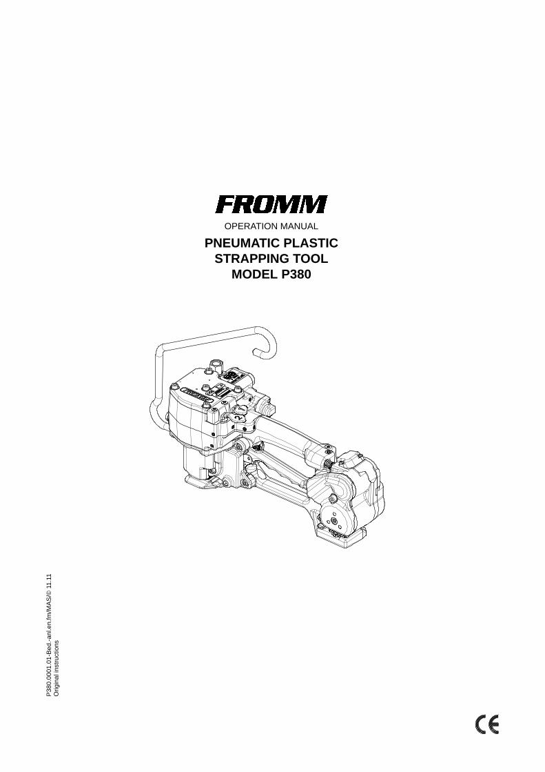
OPERATION MANUAL
PNEUMATIC PLASTIC STRAPPING TOOL
MODEL P380
P380
.000
1.01
-Bed
.-anl
.en.
fm/M
AS/©
11.
11O
rigin
al in
stru
ctio
ns

4-2 P380.0001.01-
INDEX PAGE
1 SAFETY INSTRUCTIONS 4-3
2 WARRANTY CONDITIONS AND LIABILITY 4-4
3 APPROPRIATE USE 4-4
4 CHART OF TYPES P380 4-4
5 TECHNICAL DATA 4-4
6 ACCESSORIES 4-5
7 INSTALLATION 4-67.1 Compressed air connection. . . . . . . . . . . . . . . . . . . . . . . . . . . . . . . . . . . . . . . 4-67.2 Suspension of tool . . . . . . . . . . . . . . . . . . . . . . . . . . . . . . . . . . . . . . . . . . . . . . 4-67.3 Adjustments. . . . . . . . . . . . . . . . . . . . . . . . . . . . . . . . . . . . . . . . . . . . . . . . . . . 4-7
8 OPERATING CONTROLS 4-7
9 OPERATION 4-89.1 Feeding the strap around the package . . . . . . . . . . . . . . . . . . . . . . . . . . . . . . 4-89.2 Inserting the lower strap . . . . . . . . . . . . . . . . . . . . . . . . . . . . . . . . . . . . . . . . . 4-89.3 Inserting the upper strap . . . . . . . . . . . . . . . . . . . . . . . . . . . . . . . . . . . . . . . . . 4-89.4 Tensioning the strap . . . . . . . . . . . . . . . . . . . . . . . . . . . . . . . . . . . . . . . . . . . . 4-99.5 Sealing the straps . . . . . . . . . . . . . . . . . . . . . . . . . . . . . . . . . . . . . . . . . . . . . . 4-99.6 Removing the tool . . . . . . . . . . . . . . . . . . . . . . . . . . . . . . . . . . . . . . . . . . . . . . 4-99.7 Seal - Control. . . . . . . . . . . . . . . . . . . . . . . . . . . . . . . . . . . . . . . . . . . . . . . . . 4-10
10 PNEUMATIC SCHEMATIC 4-10
11 EXCHANGE OF WEARING PARTS 4-1111.1 Exchange of tensioning wheel and slide plate. . . . . . . . . . . . . . . . . . . . . . . . 4-1111.2 Exchange of welding gripper . . . . . . . . . . . . . . . . . . . . . . . . . . . . . . . . . . . . . 4-1211.3 Exchange of welding stop gripper, stop gripper and cutter . . . . . . . . . . . . . . 4-13
12 MAINTENANCE 4-1412.1 Air unit . . . . . . . . . . . . . . . . . . . . . . . . . . . . . . . . . . . . . . . . . . . . . . . . . . . . . . 4-14
13 CLEANING 4-14
14 SERVICE / REPAIR 4-14

1 SAFETY INSTRUCTIONSRead these instructions carefully. Failure to follow these instructions can result in severe personal injury.
Eye injury hazardFailure to wear safety glasses with side shields can result in severe eye injury or blindness. Always wear safety glasses with side shields which conform to ANSI Standard Z87.1.
OperationTool must not be used by persons not properly trained in their use. Before tensioning strap, read and understand the tool operating instructions. Failure to follow the operating instructions or improper load positioning could result in strap breakage.Become familiar with your tool and keep fingers away from areas that can pinch or cut.
Tool hazardsA well maintained tool is a safe tool!Check tool regularly for broken or worn parts. Do not operate a tool with broken or worn parts.Never modify any tool. Modification can result in severe bodily injury.
JointsYou are fully responsible to review the joints made by your tool. Become familiar with the seal control and seal adjustment described in this operation manual. Misformed joints may not secure the load and could cause serious injury. Never handle or ship any load with improperly formed joints.
Dispensing strapOnly dispense strap from a dispenser specifically designed for strap.Tuck strap end back into dispenser when not in use.
Strap warningsNever use strap as a means of pulling or lifting loads. Failure to follow these warnings can result in severe personal injury.
Fall hazardKeep your working area tidy. Untidiness of your working area may cause a risk of injury. Maintaining improper footing and/or balance when operating the tool can cause you to fall. Before tensioning and especially in elevated areas, always establish good balance. Both feet should be securely placed on a flat, solid surface, especially when working in elevated areas. Do not use the tool when you are in an awkward position.Pay attention to the rules and regulations for preventions of accident which are valid for the work place.
Strap breakage hazardImproper operation of the tool, excessive tensioning, using strap not recommended for this tool or sharp corners on the load can result in a sudden loss of strap tension or in strap breakage during tensioning, which could result in the following:
• A sudden loss of balance causing you to fall.• Both tool and strap flying violently towards
your face.Note as follows:
• If the load corners are sharp, use edge protectors.
• Place the strap correctly around a properly positioned load.
• Positioning yourself in-line with the strap, during tensioning and sealing, can result in severe personal injury from flying strap or tool. When tensioning or sealing, position yourself to one side of the strap and keep all bystanders away.
• Use the correct strap quality, strap width, strap gauge and strap tensile strength recommended in this manual for your tool. Using strap not recommended for this tool can result in strap breakage during tensioning.
Cutting tensioned strapWhen cutting strapping, use the proper strapping cutter and keep other personnel and yourself at a safe distance from the strap. Always stand to side of the strap, away from the direction the loosened strap end will fly. Use only cutters designed for strap and never hammers, pliers, hacksaws, axes, etc.
4-3P380.0001.01.enT1.fm
2 WARRANTY CONDITIONS AND LIABILITY FROMM Holding AG warrants all its strapping tools and machine heads during a period of 24 months from the date of installation at the end-user's sight by the distributor, however, not later than 30 months from the date of shipment to the distributor of FROMM Holding AG.The warranty includes all deficiencies clearly resulting from poor manufacturing or faulty materials. Damage claims as a result of production shutdowns and claims for damage to persons and to property resulting from warranty deficiencies cannot be asserted by the customer.The warranty excludes:• wearing parts (tensioning wheels, cutters, punches, dies, notching knifes, grippers, batteries and motors),• deficiencies resulting from improper installing, incorrect handling and maintaining the tool,• deficiencies resulting from using the tool without or with defective security- and safety devices,• disregard of directions in the operation manual,• arbitrary modifications of the tool,• deficient control of wearing parts,• deficient repair works of the tool. • Use of consumable products not recommended by FROMM Holding AGWe reserve the right to modify the product at any time in order to improve its quality.
3 APPROPRIATE USEThe tool model P380 has been designed to strap packages with plastic strapping exclusively.The warranty / liability excludes:
• non appropriate use of the tool,• disregard of directions in the operation manual,• disregard of control- and maintenance instructions.
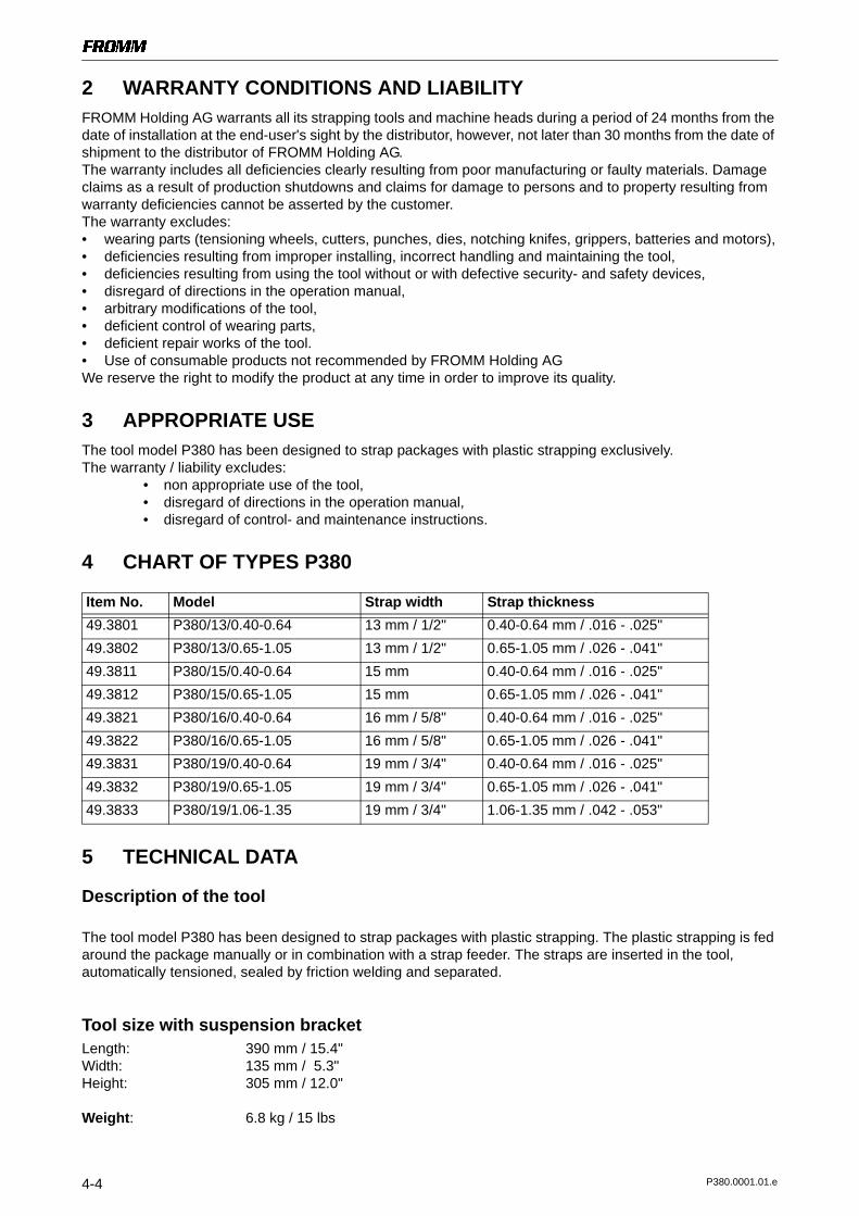
4 CHART OF TYPES P380
Item No. Model Strap width Strap thickness 49.3801 P380/13/0.40-0.64 13 mm / 1/2" 0.40-0.64 mm / .016 - .025"49.3802 P380/13/0.65-1.05 13 mm / 1/2" 0.65-1.05 mm / .026 - .041"49.3811 P380/15/0.40-0.64 15 mm 0.40-0.64 mm / .016 - .025"49.3812 P380/15/0.65-1.05 15 mm 0.65-1.05 mm / .026 - .041"49.3821 P380/16/0.40-0.64 16 mm / 5/8" 0.40-0.64 mm / .016 - .025"49.3822 P380/16/0.65-1.05 16 mm / 5/8" 0.65-1.05 mm / .026 - .041"49.3831 P380/19/0.40-0.64 19 mm / 3/4" 0.40-0.64 mm / .016 - .025"49.3832 P380/19/0.65-1.05 19 mm / 3/4" 0.65-1.05 mm / .026 - .041"49.3833 P380/19/1.06-1.35 19 mm / 3/4" 1.06-1.35 mm / .042 - .053"
5 TECHNICAL DATA
Description of the tool
The tool model P380 has been designed to strap packages with plastic strapping. The plastic strapping is fed around the package manually or in combination with a strap feeder. The straps are inserted in the tool, automatically tensioned, sealed by friction welding and separated.
Tool size with suspension bracketLength: 390 mm / 15.4"Width: 135 mm / 5.3"Height: 305 mm / 12.0"
Weight: 6.8 kg / 15 lbs
4-4 P380.0001.01.e

Sound informationThe A-weighted equivalent continuous sound level at the work place of the machine operator is typical 78 dB (A). This value was determined according to DIN EN 11204 (07.96).Deviation K: 3 dB
Vibration informationThe weighted effective value of the acceleration typically amounts to less than 2.5m/s2.This value was determined according to DIN EN 28 662 T1 (01.93).Deviation K: 0.15 m/s2
Strap materialStrap qualities: PET (Polyester) and PP (Polypropylene) plain or embossed.
Use only plastic straps recommended by your sales shop (name and address on the rear of the operation manual).
Strap dimensions: 13.0 -19.0mm / 1/2" - 3/4" X 0.4 - 1.35 mm / .016" - .053" (see chart of types) Use only plastic straps with the correct strap dimensions for your tool.
Strap tensionTensioning force*: Adjustable from 600 - max. 2000N / 135 - 450 lbs at 6 bar / 87 psi. Tensioning speed*: 120 - max. 260 mm/s / 4.7" - max. 10.2" per second with steady air pressure of
6 bar / 87 psi
SealType of seal: Friction weld sealingStrength of seal*: Up to approx. 75% of strap tensile strength* The value depends on the strap quality.
Package dimensions
Diameter of round / circular goods:
min 2 x ø70mm min ø 240mm
Width:
min 80mm
6 ACCESSORIES
Use only parts and accessories mentioned in the operating instruction. Using other parts or accessories can cause injuries to you and other persons.
Plate (option)
P38.1204
N1.2223
P38.0120
P38.1206
N1.2227
P38.0121
For the usage of the tool on packages with sensitive surface there can two plastic plates be assembled to the bottom side of the tool.
Every plate including fixation screws can be ordered with item number P38.0120 or P38.0121(see drawing) respectively.
4-5P380.0001.01.enT1.fm

7 INSTALLATION
7.1 Compressed air connectionThe compressed air should be connected to the tool preferably by a quick disconnector.It is very important to clean the compressed air with an air unit consisting of a separator for water and dirt, a pressure regulator with a manometer and a lubricator (see sketch).
app. 2% fallShut off valve
Drain of main air line
Main air line min. 2"Air line min. 1/2"
Pressure adjustment valvewith manometer
Filter with
Lubricator (1 - 2 drops/min)
water separatorwith shut off valve Air hose
max. length 5m (16ft.)min. Ø inside 10mm
Coupling min. G1/4
Air unit G3/8
Air pressureJoining thread: G1/4Air pressure: The maximum air pressure allowed is 6.0 bar / 87 psi.Air flow of air unit: Min. 520 Nl/min / 18.4 cu.ft /min with a maximum pressure drop of 0.5 bar/ 7.25 psi.
Air consumptionTensioning: 4.9 Nl / 0.18 cu.ft uncompressed air per second with the air motor running.Sealing: 8.6 Nl / 0.30 cu.ft uncompressed air per second with the air motor running.
Oil for air unitHL resp. CL ISO-VG 10
7.2 Suspension of toolIt is possible to suspend the tool on a spring loaded balancer using the suspension bracket which is supplied with the tool. The suspension bracket has been designed in such a way, that the tool can be used for all three working positions.
4-6 P380.0001.01.e
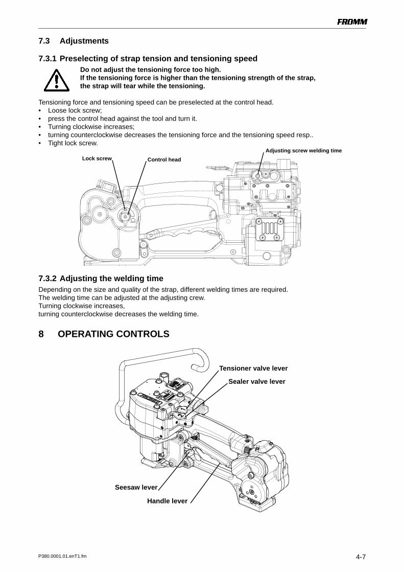
7.3 Adjustments
7.3.1 Preselecting of strap tension and tensioning speedDo not adjust the tensioning force too high.If the tensioning force is higher than the tensioning strength of the strap, the strap will tear while the tensioning.
Tensioning force and tensioning speed can be preselected at the control head. • Loose lock screw;• press the control head against the tool and turn it.• Turning clockwise increases;• turning counterclockwise decreases the tensioning force and the tensioning speed resp..• Tight lock screw.
Lock screw Control headAdjusting screw welding time
7.3.2 Adjusting the welding time Depending on the size and quality of the strap, different welding times are required.The welding time can be adjusted at the adjusting crew.Turning clockwise increases, turning counterclockwise decreases the welding time.
8 OPERATING CONTROLS
Handle lever
Tensioner valve lever
Sealer valve lever
Seesaw lever
4-7P380.0001.01.enT1.fm

9 OPERATION
9.1 Feeding the strap around the packageThe strapping is fed around the package as illustrated.
Warning! The plastic strap which will be welded must be free from oil, grease and other dirt.Dirty plastic straps can't be welded correct.
9.2 Inserting the lower strap
Lower strap
Stop gripper
Seesaw lever
Lift and hold the handle lever with the right hand.The left hand inserts the free end of the strap. First between welding gripper and the welding stop gripper and then under the stop gripper until it hits the strap stop. Make sure that the strap is well aligned to both strap stops!With the thumb move the seesaw lever up.The strap is locked.
Do not release the handle lever.
9.3 Inserting the upper strap
Upper strap
The left hand inserts the upper strap under the welding gripper, over the stop gripper and between tensioning wheel and sliding jaw until it hits the strap stop.Pull on the strap until the strap sling touches the package.Release the handle leverThe strap guides close and the tensioning wheel will move down to the strap.
4-8 P380.0001.01.e

9.4 Tensioning the strap Press down the tensioner valve lever and then release it again after the desired strap tension has been reached. The tensioning operation can be interrupted and restarted at any time.
9.5 Sealing the strapsPress down and release immediately the sealing valve lever. The plastic strap is welded and cut off from the strap coil at the same time.
After the expiration of the adjusted sealing time, the seal has to cool down approx. 2 sec.During that time, the tool can not be removed from the sealed strap.
After the expiration of the adjusted cooling time the welding jaw move upwards.Now the tool can be removed from the strap.
9.6 Removing the tool Pull up the handle lever, pull the tool right and off the strapping.
4-9P380.0001.01.enT1.fm

9.7 Seal - Control A regular control of the seal is necessary. The seal can be examined visually.Make a seal, peel it apart and examine it as follows:
Correct seal The seal must be completely welded over the whole width of the strap on a length of ca. 19 mm. Minor quantities of fused plastic may overflow on sides.
Welding time too shortThe plastic strap is not welded over the whole width of the strap. The seal efficiency is insufficient. Warning! Straps with insufficient seal strength must be removed from the package! Adjust the welding time.
Welding time too longIf the welding time is too long the straps are overheated. The fused plastic overflows on both sides of the straps. The seal efficiency is affected. Warning! Straps with insufficient seal strength must be removed from the package!Adjust the welding time.
10 PNEUMATIC SCHEMATIC
P
1
2
34
56
5
1
2
3
12
1
2
3
4
13
1
2
1
1
2
3
4
2
1
2
3
4
1
3
2
48
1
2
91
3
2
4
10
1
2
34
14
1
2
3
4
7
1
2
34
15
a
b
1
2
11 16
6
41 Tensioner valve2 Tension force control valve3 Tensioning motor4 Exhaust silencer5 Welding valve6 Throttle 0,67 Welding motor valve8 Welding time valve9 Welding motor10 Cooling time valve11 Welding cylinder12 Welding signal valve13 Turn off valve14 Cooling signal valve15 Welding turn off valve16 Cylinder reverse stop
a Tensioner valve leverb Welding valve lever
4-10 P380.0001.01.e

11 EXCHANGE OF WEARING PARTS
Before any maintenance work always disconnect the tool from the air supply.
11.1 Exchange of tensioning wheel and slide plate• Unscrew end cover P38.0114 and remove it;• Remove the tensioning wheel together with the bearing N3.1172 from the tool;
If additionally the slide plate has to be changed:• Unscrew slide plate P38.1151.
N1.1808
P38.0114
N21.2102
P35.2027
Tensioning wheel P35.2026
N3.1172
Molykote BR2 plus
P38.1151
Assembling in opposite order.
Assembly advise• The sliding plate remains movable also after the screws N1.1808 has been fixed.• Lubricate the internal tooth system of the tensioning wheel with Molykote BR2 plus.• Observe the position of the tensioning wheel.
The direction of rotation of the tensioning wheel is marked at the front of the tensioning wheel .• The parallel pin N21.2102 must be inserted in the guide of the strap guide lever P38.1150 when
assembling the end cover.
4-11P380.0001.01.enT1.fm

11.2 Exchange of welding gripper• Disassemble the both screws N1.1114 and N1.1132 together with the
conical spring washers N1.6237; • Pull off the complete welding drive;• Remove the ball cage P38.1199 and the balls N3.1702 from the welding gripper;• Disassemble the security ring N2.1121;• Remove the bolt P38.1201.
Klüber Isoflex Alltime SL2 Klüber Isoflex NBU 15
Welding gripper
P38.1199
P38.1201
N2.1121
N3.1702
N1.1114
N1.6237
N1.6237
N1.1132
Assembling in opposite order.
Assembly advise• Lubricate the rocker and the bolt P38.1201 in the area of the welding jaw with Klüber Isoflex NBU 15.• Lubricate the balls, ball cage and the running surface of the balls on the welding gripper with
Klüber Isoflex Alltime SL2.
4-12 P380.0001.01.e

11.3 Exchange of welding stop gripper, stop gripper and cutter• Put a piece of plastic strap between stop gripper and base plate;• Screw off base plate;• Disassemble the screws N1.1306;• Take the welding stop gripper P38.1187 from the base plate.
• Disassemble the end cover P38.0119;• Take the cutter from the tool;• Pull off the stop gripper.
Loctite 222 N1.1306 N1.1168 N1.6407
N1.6503 N1.6237 N11.1119
N1.1132 P38.1187
P38.0119
Stop gripper
Cutter
N21.5206
Mobilux EP2
Base plate
Assembling in opposite order.
Assembly advise• Pay attention to the assembling position of the cutter (see drawing).• Glue the screws N1.1306 with Loctite 222.
4-13P380.0001.01.enT1.fm

12 MAINTENANCEDepending on the working conditions and the use of the tool the following maintenance has to be made periodically:
12.1 Air unit
• Checking the air-pressure daily (never exceed 6 bar / 87psi)• Checking oil-level daily• The water separator must be emptied before it is full (unless automatic)• The filter has to be cleaned following the instructions of the manufacturer of the air- unit• Check the function and proper adjustment of the lubricator daily (approximately 1-2 drops/min.)
Before any maintenance work always disconnect the tool from the air supply.
13 CLEANINGClean tension- and sealing parts from strap abrasion regularly using compressed air. For that are additional openings existent in the base plate.Do not use any mechanical tool for cleaning.When cleaning the surface of the tool do not use water or aggressive solvents!
Openings for blowingout the tensioning elements
14 SERVICE / REPAIRServicing and repair work must only be carried out by authorized service centres.If the tool breaks down or does no longer operate do not disassemble it. Send it fully assembled to the local service centre (see name and address on the rear page of this manual). Use original packing.
The pneumatic plastic strapping tool P380 is a high performance tool. We strongly recommend you to have it serviced by an authorized service shop after 12 months at the latest if used one shift per day. If used two or more shifts per day the tool has to be serviced after a shorter period of time.
4-14 P380.0001.01.e