Embed Size (px)
Citation preview

1
ScalesScales
• It is impractical to draw buildings, plots of land, and large parts of buildings such as It is impractical to draw buildings, plots of land, and large parts of buildings such as doors and windows to their full size. doors and windows to their full size.
• They simply would not fit on a piece drawing paper. Instead they are normally They simply would not fit on a piece drawing paper. Instead they are normally drawn to a smaller reduced size. The size they are reduced will be to a ratio of the drawn to a smaller reduced size. The size they are reduced will be to a ratio of the real item: real item: • Twice as small 2:1Twice as small 2:1• Ten times smaller 10:1 etcTen times smaller 10:1 etc
• When drawings are drawn in this way they are called When drawings are drawn in this way they are called SCALED DRAWINGSSCALED DRAWINGS• To draw buildings and objects to a scale, recognised ratios called To draw buildings and objects to a scale, recognised ratios called SCALESSCALES are are
used to relate real dimensions and measurements to a drawing.used to relate real dimensions and measurements to a drawing.
Building reduced in size to fit on drawing paperBuilding reduced in size to fit on drawing paper

2
ScalesScales
1:11:1 Full size used for unusual details or templatesFull size used for unusual details or templates
1:21:21:51:51:101:10
Complicated building detailsComplicated building details
1:201:201:501:501:1001:1001:2001:200
Plans, elevations and sectionsPlans, elevations and sections
1:2001:2001:5001:5001:12501:1250
Site plansSite plans
1:12501:12501:25001:2500 Block or location plansBlock or location plans
The main scales The main scales or ratios used in or ratios used in construction construction drawings are-:drawings are-:

3
Use of scalesUse of scales
• The choice of scale will depend on two things:The choice of scale will depend on two things:
1.1. The size of the object to be drawnThe size of the object to be drawn
2.2. The amount of detail that needs to be shownThe amount of detail that needs to be shown
• A scale is used to measure distances on drawings and for taking A scale is used to measure distances on drawings and for taking measurements of a drawing. measurements of a drawing.
15.35 m15.35 m
• The distance shown above represents 15.35m it will be to a scale.The distance shown above represents 15.35m it will be to a scale.
• If scaled dimensions and written dimensions disagree, then the If scaled dimensions and written dimensions disagree, then the written dimension should always be used.written dimension should always be used.
• The scale shows how much smaller the plan or object is to its original The scale shows how much smaller the plan or object is to its original size.size.

4
Use of scalesUse of scales
• In a house drawing to a scale of 1:20 :In a house drawing to a scale of 1:20 :• 1 mm will represent 20 mm1 mm will represent 20 mm• 2 mm will represent 40 mm2 mm will represent 40 mm• 10 mm will represent 200 mm10 mm will represent 200 mm• 100 mm will represent 2000 mm or 2 m100 mm will represent 2000 mm or 2 m
• To a scale of 1: 10 100 mm will represent 1,000 mm or 1 mTo a scale of 1: 10 100 mm will represent 1,000 mm or 1 m• To a scale of 1: 100 100 mm will represent 10,000 mm or 10 mTo a scale of 1: 100 100 mm will represent 10,000 mm or 10 m• To a scale of 1: 50 100 mm will represent 5,000 mm or 5 mTo a scale of 1: 50 100 mm will represent 5,000 mm or 5 m• To a scale of 1:5 250 mm will represent 1,250 mm or 1.250 mTo a scale of 1:5 250 mm will represent 1,250 mm or 1.250 m• To a scale of 1:200 150 mm will represent 30,000 mm or 30 mTo a scale of 1:200 150 mm will represent 30,000 mm or 30 m
• It is simply a matter of It is simply a matter of multiplyingmultiplying the scale measurement by the scale ratio the scale measurement by the scale ratio• 1: (10) x 100mm = 1000mm or 1m1: (10) x 100mm = 1000mm or 1m• 1: (50) x 100mm = 5000mm or 5m1: (50) x 100mm = 5000mm or 5m• 1: (200) x 150mm = 30,000mm or 30m1: (200) x 150mm = 30,000mm or 30m

5
Student ActivityStudent Activity
• The drawing shows a ground The drawing shows a ground
floor plan of a small bungalow floor plan of a small bungalow
drawn to a scale of 1:100.drawn to a scale of 1:100.
• Using a scale rule complete Using a scale rule complete
the table by inserting all the the table by inserting all the
required dimensions.required dimensions.
6
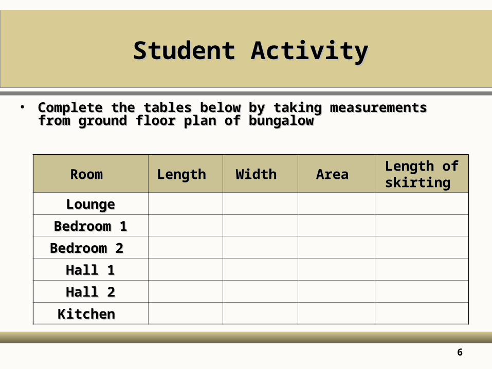
Student ActivityStudent Activity
• Complete the tables below by taking measurements from ground Complete the tables below by taking measurements from ground floor plan of bungalowfloor plan of bungalow
RoomRoom LengthLength WidthWidth AreaArea Length of Length of skirtingskirting
LoungeLounge
Bedroom 1Bedroom 1
Bedroom 2Bedroom 2
Hall 1Hall 1
Hall 2Hall 2
KitchenKitchen

7
Student ActivityStudent Activity
• Insert the width of all the windows of the bungalowInsert the width of all the windows of the bungalow
WindowsWindows WidthWidth
W1W1
W2W2
W3W3
W4W4
W5W5

8
Student ActivityStudent Activity
Scale Rule – Scale 1:100 Scale Rule – Scale 1:100 • Mark on the scale rule the line representing 1.6m to a Mark on the scale rule the line representing 1.6m to a
scale of 1:100scale of 1:100

9
Student ActivityStudent Activity
Scale Rule – Scale 1:20 Scale Rule – Scale 1:20 • Mark on the scale rule the line representing 1.7m to a Mark on the scale rule the line representing 1.7m to a
scale of 1:20scale of 1:20

10
Student ActivityStudent Activity
Scale Rule – Scale 1:50 Scale Rule – Scale 1:50 • Mark on the scale rule the line representing 6m to a Mark on the scale rule the line representing 6m to a
scale of 1:50scale of 1:50

11
Student ActivityStudent Activity
Scale Rule – Scale 1:1250 Scale Rule – Scale 1:1250 • Mark on the scale rule the line representing 130m to a Mark on the scale rule the line representing 130m to a
scale of 1:1250scale of 1:1250

12
Drawing LinesDrawing Lines
Lines should be of THREE thicknesses1. Thick
0.75 – 1mm thick for borders and drawing outlines
2. Medium 0.35 – 0.5mm thick ½ the thickness of the thick lines for hatching
3. Fine 0.2 – 0.25 mm thick ½ the thickness of the medium lines for dimension lines.
350mm
600mm

13
Dimension LinesDimension Lines
• All drawings must be clear and accurate and easily All drawings must be clear and accurate and easily
understood by everyone who uses them.understood by everyone who uses them.
• In order to achieve this method of layout, symbols and In order to achieve this method of layout, symbols and
abbreviations have been standardised ( See BS 1192 ).abbreviations have been standardised ( See BS 1192 ).
• Next slide are some examples of the most common Next slide are some examples of the most common
different lines and what they represent on working different lines and what they represent on working
drawings.drawings.

14
Dimension LinesDimension Lines
• ThickThick Main outlinesMain outlines
• MediumMedium General details and outlinesGeneral details and outlines
• ThinThin Construction and dimension LinesConstruction and dimension Lines
• BreaklineBreakline Breaks in the continuity of a drawingBreaks in the continuity of a drawing
• Thick chainThick chain Pipe lines, drains and servicesPipe lines, drains and services
• Thin chainThin chain Centre linesCentre lines
• Section lineSection line Showing the position of a section cut, Showing the position of a section cut,
the pointers show the direction of the the pointers show the direction of the
viewview
• Broken lineBroken line Shows hidden detailsShows hidden details
• Dimension lineDimension line Indicates the distance between two points Indicates the distance between two points
15
Drawing NotationDrawing Notation
1 2 3 4 5 6 7 8 9
UP
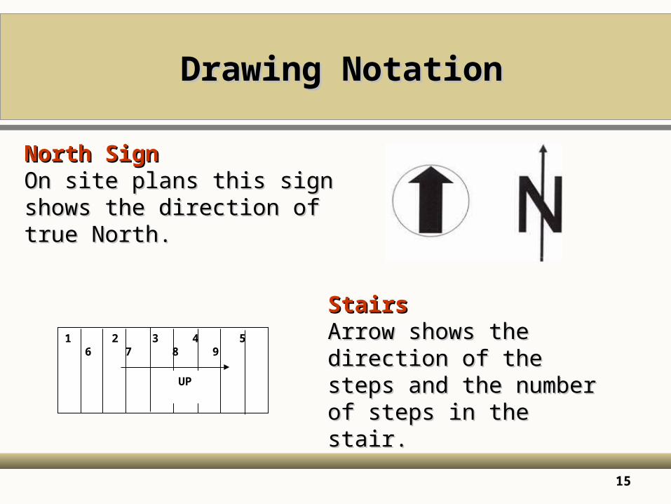
North SignNorth SignOn site plans this sign shows the On site plans this sign shows the direction of true North.direction of true North.
StairsStairsArrow shows the direction of Arrow shows the direction of the steps and the number of the steps and the number of steps in the stair.steps in the stair.

16
Drawing NotationDrawing Notation
WindowsWindowsA dotted line in the shape of a pointed arrow indicates the A dotted line in the shape of a pointed arrow indicates the haging edge of a window sashhaging edge of a window sash
Side hungSide hung
Top hungTop hung
Bottom hungBottom hung

17
Dimension LinesDimension Lines
• These should be thin lines, the ends can be shown in several waysThese should be thin lines, the ends can be shown in several ways
• Open arrow head showing outside measurementOpen arrow head showing outside measurement
• Closed arrow head showing inside measurementClosed arrow head showing inside measurement
Running totals
350mm350mm
0.5m0.5m
1000 1000 2500 2500 50 50 3500 3500
18
Dimension LinesDimension Lines
• Written Written dimension on horizontal linesdimension on horizontal lines should always be should always be
on top, preferably in the centre.on top, preferably in the centre.
• Written Written dimensions on vertical linesdimensions on vertical lines should be to the left should be to the left
and preferably in the centre.and preferably in the centre.
• All dimensions should be read from the bottom right All dimensions should be read from the bottom right
hand corner.hand corner.

19
SymbolsSymbols
• Symbols are graphical illustrations, which are used to represent the different building materials and components in a building drawing.
• It was the custom to colour drawings, particularly the drawings submitted to the local authority for planning permission.
• Sadly the practice is rarely used as it is slow and time consuming.
• However is still the custom to colour in the position of a building in a block plan to show the position of the building and its surrounding boundaries.
• Next slide are some of the most common symbols used and what they represent.

20
SymbolsSymbols

21
Lettering DrawingsLettering Drawings
• The majority of drawings will require The majority of drawings will require lettering and numberinglettering and numbering..
• This may vary from very little or none on a design to a great deal of production This may vary from very little or none on a design to a great deal of production drawings and schedules.drawings and schedules.
• Various techniques can be used, their application depending upon the type of Various techniques can be used, their application depending upon the type of drawing and its use.drawing and its use.
• The quickest method is by The quickest method is by handhand and it is important to develop a neat and and it is important to develop a neat and accurate style from the beginning.accurate style from the beginning.
• Poor lettering can ruin an otherwise good drawing.Poor lettering can ruin an otherwise good drawing.
• Any lettering that is used, whether for notes, titles or headings, must be clear Any lettering that is used, whether for notes, titles or headings, must be clear and easy to read.and easy to read.
• Good use of lettering will not only give information but can Good use of lettering will not only give information but can improve the improve the presentation of the drawingpresentation of the drawing..
• Faint guide lines could be drawn to help you practice the letters and numbers.Faint guide lines could be drawn to help you practice the letters and numbers.

22
Lettering DrawingsLettering Drawings
A B C D E F G H I J K L M N O P Q R S T U V W X Y ZA B C D E F G H I J K L M N O P Q R S T U V W X Y Z
1 2 3 4 5 6 7 8 9 10 111 2 3 4 5 6 7 8 9 10 11
• The size of the letters depends on the size of the drawing paper.The size of the letters depends on the size of the drawing paper.• For A1, A2 and A3 sized paper, the letters should be between 7 mm For A1, A2 and A3 sized paper, the letters should be between 7 mm
and 4 mm.and 4 mm.• For A4 sized paper the letters should be between 5 mm and 3 mmFor A4 sized paper the letters should be between 5 mm and 3 mm

23
Title PanelsTitle Panels
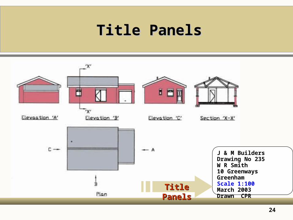
• The The British Standard 1192British Standard 1192 sets the following recommendations. sets the following recommendations.• Job Title and numberJob Title and number
• Name and Address of issuing firm or practiceName and Address of issuing firm or practice
• Description of the drawingDescription of the drawing
• ScaleScale
• Date the drawing was completedDate the drawing was completed
• Author of drawingAuthor of drawing
• Checker of the drawingChecker of the drawing
• Drawing numberDrawing number
• Many construction firms have their drawing paper pre-printed with a Many construction firms have their drawing paper pre-printed with a title panel.title panel.
• The panel should be at the The panel should be at the bottom right hand corner bottom right hand corner of the drawing.of the drawing.
24
Title PanelsTitle Panels
J & M BuildersDrawing No 235 W R Smith10 GreenwaysGreenhamScale 1:100 March 2003Drawn CPRTitle PanelsTitle Panels

25
AbbreviationsAbbreviations
• Abbreviations are a simple way of Abbreviations are a simple way of conveying information on conveying information on
drawings, reducing words to first lettersdrawings, reducing words to first letters, e.g. rain water pipe , e.g. rain water pipe
becomes R.W.P. becomes R.W.P.
• They allow the maximum information to be included on the drawing They allow the maximum information to be included on the drawing
in a concise way.in a concise way.
• Abbreviations Abbreviations have to be used in context have to be used in context e.g. MS stands for Mild e.g. MS stands for Mild
Steel in the context of construction but it could also be an Steel in the context of construction but it could also be an
abbreviation for some other word in another situation.abbreviation for some other word in another situation.
• Avoid Avoid making up your ownmaking up your own abbreviations as these can lead to abbreviations as these can lead to
confusion.confusion.

26
AbbreviationsAbbreviations
• Aggregate agg
• Air brick Ab• Aluminium al• Asbestos asb• Asphalt asph• Bitumen bit• Boarding bdg• Brickwork bwk• BS Beam BSB• Building bldg• Cast iron CI• Cement ct• Column col• Concrete
conc
• Copper cu• Damp proof course dpc• Discharge pipe DP• Foundation fdn• Hardcore hc• Hardboard hdbd• Hardwood hwd• Inspection chamber IC• Insulation insul• Tongued and grooved t&g• Joist jst• Plasterboard pbd• Reinforced conc RC

27
Graphical SymbolsGraphical Symbols
• These are small These are small standard picturesstandard pictures used to reduce used to reduce the amount of drawing detail required on individual the amount of drawing detail required on individual drawings.drawings.
• Abbreviations and graphical symbols are often used Abbreviations and graphical symbols are often used together to give complete information.together to give complete information.

28
Representation of components - Representation of components - fittingsfittings
SinkSink BathBath BidetBidet ToiletToilet Hot & Cold Hot & Cold Water drain Water drain
offoff
Cold water Cold water CisternCistern
Hot water Hot water CylinderCylinder
Surface Surface waterwater
Stop Stop valvevalve
Drain or Drain or Sewer FlowSewer Flow
Foul waterFoul water Rain water Rain water headhead
Rainwater Rainwater outletoutlet
GulleyGulley
RadiatorRadiator Towel railTowel rail BoilerBoiler CookerCooker PumpPump