Embed Size (px)
Citation preview

7/29/2019 1-s2.0-S0266353806000364-main
http://slidepdf.com/reader/full/1-s20-s0266353806000364-main 1/8
Composite flywheels for energy storage
Jerome Tzeng *, Ryan Emerson, Paul Moy
US Army Research Laboratory, Weapons and Materials Research Directorate, Aberdeen Proving Ground, MD 21005-5066, USA
Received 17 January 2006; accepted 18 January 2006Available online 24 March 2006
Abstract
Composite flywheels for energy storage have been proposed and investigated for the past several decades. Successful applications are,however, limited due to the inability to predict the performance – especially the long-term durability. In this investigation, a comprehen-sive study was proposed with the intent to implement composites in high performance flywheels. The potential failure mechanism of fly-wheels constructed with fiber composites was evaluated. Analytical codes for predicting elastic and viscoelastic (long-term) behavior wasdeveloped for flywheel design. Material characterization and test matrices were proposed to design flywheels with maximum perfor-mance. Component level test methods and devices were developed to validate flywheel performance. Finally, a methodology incorporat-ing these studies is presented for the design and manufacture of composite flywheels.Ó 2006 Elsevier Ltd. All rights reserved.
Keywords: Composite flywheel; Cylinder; Flywheel monitor; Composite
1. Introduction
Composite flywheels are currently being developed forenergy storage. The energy stored in the flywheel can beretrieved to supply power for electrical drive machinery.To satisfy the high performance and low-weight con-straints, high-strength carbon fiber composites are thematerials of choice for flywheel construction. Recently, sev-eral composite flywheels have been developed for commer-cial power generation and vehicles, such as buses andtrains. In the government sector, NASA intends to havecomposite flywheels in the space station for energy storage.Flywheels have also been proposed for satellite attitude
control. There are investigations of hybrid and all-electriccombat vehicles and weapons. Composite flywheels arecrucial components of the systems. There have beennumerous R&D programs on composite flywheels [1–3]in the past. Several programs have been conducted innational laboratories for nuclear applications. Some long-term programs were performed in academia and industry.
In spite of much effort, there are few successful composite
flywheels built and used in practical applications. Theshortcomings that hinder the use of composite materialsin flywheel applications will be illustrated and discussed.A new approach for design and testing is also proposedin the following sections.
The inertial stresses in a flywheel during operation(high-speed rotation) are dominant in the circumferentialdirection and, consequently, composite flywheel rotorsare usually filament wound with the fiber reinforcementsoriented in this direction. However, tensile stress is alsodeveloped in the radial direction due to mismatches inthe growth of the rotor as well as Poisson effects. Since fil-
ament wound composite rotors lack reinforcement throughthe radial thickness, these rotors generally fail by radialdelamination prior to fiber breakage in the circumferentialdirection. An elastic thick-walled composite cylinder anal-ysis was developed to determine the stress and strain pro-files in a flywheel. Fig. 1 shows the definition of stresscomponents and coordinate systems used in the analysis.Fig. 2 illustrates the stress profile in a graphite compositecylinder with 3 and 6-in. inner and outer radius, respec-tively, subjected to 50,000 rpm rotational load. As shownin the analysis, the maximum hoop stress is around 95 ksi
0266-3538/$ - see front matter Ó 2006 Elsevier Ltd. All rights reserved.
doi:10.1016/j.compscitech.2006.01.025
* Corresponding author. Tel.: +1 410 306 0959; fax:+1 410 306 0759.E-mail address: [email protected] (J. Tzeng).
www.elsevier.com/locate/compscitech
Composites Science and Technology 66 (2006) 2520–2527
COMPOSITES
SCIENCE AND
TECHNOLOGY

7/29/2019 1-s2.0-S0266353806000364-main
http://slidepdf.com/reader/full/1-s20-s0266353806000364-main 2/8
and is below the strength limit. However, the radial stressin this case is about 10 ksi – far exceeding the strength inthat direction. These stresses were calculated using themodel developed in [4].
By assembling the rotor with a press-fit or shrink-fit,
compressive radial stress is built-in, which helps to mitigatethe radial stresses that develop during operation. Conse-quently, higher rotor performance is realized by avoidingpremature failure by radial delamination. The press-fit pro-cess, however, might induce significant banding and shearstresses along the axial direction of cylinder during fabrica-tion. Axial reinforcement might therefore be needed for aflywheel to achieve a higher speed or performance. Withthis in mind, a series of material tests were performed todetermine the tensile and shear properties of laminates inthis investigation. The test results will be used to designthe layup of a composite rotor subjected to various loading
conditions, including those induced by the manufacturingprocesses.
To achieve high performance, the stresses in a compositerotor must be high during operation. Accordingly, thelong-term behavior of the composite materials used in fly-wheel rotors is particularly critical. Over time, the stressand strain profiles can change in a composite flywheel – sig-nificantly affecting the structural performance. Creep andfatigue crack growth are durability concerns that lead tounbalance in the rotor. To assist in evaluating the occur-
rence of such time-dependent phenomena, a viscoelasticanalysis of flywheels was developed. Fracture propertiesof the composite laminates of interest were also evaluatedin conjunction with the potential crack growth and failuremechanism [5].
The rotor deformation needs to be monitored in order
to validate structural design and integrity. Currently,deformation of a rotating body can be measured by straingage with a split ring at the spindle or a laser measurement.The strain gage works only up to a moderate speed thenfails because of high centripetal force. The traditional laserdevice basically measures the distance change between therotor surface and the device location. However, neithermethod will be able to satisfy the measurement requiredof a high-speed rotor. A non-contact optical sensing tech-nique was developed during the investigation. The methodwill enable a real time monitor of rotor condition and willbe discussed in detail.
Recent flywheel developments for energy storage of
Army electric weapons and hybrid vehicle are discussedin this paper. Technologies to achieve high performancecomposite flywheels were developed during the course of this study. In the following section, those technologies willbe presented including analytical models, material charac-terization, component spin tests, and flywheel lifeassessment.
2. Analytical models
An analytical model is necessary to predict creep and pre-load loss due to the time dependent behavior of composites.
A viscoelastic analysis has been developed that is relevantfor thick-walled composite cylinders [6,7]. The Boltzmannsuperposition integral is used for the complete spectrum of increments of anisotropic material constants with respectto time. In the analysis, a thick composite cylinder isassumed to remain at a constant elevated temperature,and all boundary conditions are independent of time.Accordingly, the linear thermal viscoelastic problem canbe derived from the associated linear elastic problem byemploying the elastic–viscoelastic correspondence principle.
“N” layers
ba
σ
r,w
u
σθ
ω
Fig. 1. Definition of coordinate systems and stress components in arotating cylinder.
8.0 104
8.5 104
9.0 104
9.5 104
1.0 105
3 3.5 4 4.5 5 5.5 6
H o o p S t r e s s ( p s i )
0.0 100
2.0 103
4.0 103
6.0 103
8.0 103
1.0 104
3 3.5 4 4.5 5 5.5 6
Radial Stress
R a d i a l S t r e s s ( p s i )
Radius (inch)Radius (inch)
Fig. 2. Stress profile in a hoop wound composite cylinder with 3-in. inner and 6-in. outer radii subjected to 50,000 rpm rotational load.
J. Tzeng et al. / Composites Science and Technology 66 (2006) 2520–2527 2521
7/29/2019 1-s2.0-S0266353806000364-main
http://slidepdf.com/reader/full/1-s20-s0266353806000364-main 3/8
In other words, the integral constitutive equations reduceto algebraic relations, which are essentially identical tothose developed for elastic media when they are Laplace-transformed by means of the rule for convolution integrals.The elastic analysis can thus be used to derive the trans-formed viscoelastic solutions in the time domain.
The coordinate system used to model a rotor is shown inFig. 1. The governing equation can be derived from themomentum equation with anisotropic constitutive materialproperties as follows:
r 2 d2
w
dr 2þ r
dw
dr À k2
w ¼ðeC 13 À eC 12Þ
seC 33
eor Àqx2
seC 33
r 3; ð1Þ
where w is radial displacement and r is radius, x is angularvelocity and e is axial elongation, and s denotes the Laplacetransform variable. The C ij terms are material properties[4].
Eq. (1) is the governing equation in the Laplace domain.
Here and henceforth, an overbar denotes functions of theLaplace transform variable. The elastic formulation has asimilar form according to the correspondence principle.While his equation can represent any composite layer (withone set of material properties) within a multiple-layer com-posite cylinder, properties are allowed to vary from layer tolayer.
Solving Eq. (1) for w yields the complete solution asfollows:
w ¼ A1r k þ A2r
Àk þ ~wp; ð2Þ
where A1 and A2 are coefficients determined from boundary
and continuity conditions. The particular solution is ob-tained in the following expression:
~wp ¼eC 12 À eC 13
eC 33 À eC 22
eor À1
9 À k2
qx2
eC 33
r 3. ð3Þ
A set of simultaneous equations can be assembled for amultiple-layer composite cylinder. The total number of equations is determined by the number layers in the cylin-der. A numerical technique was developed, which appliesthe continuity boundary condition during the assemblyprocess of the equation set [6]. This process reduces thetotal number of the equations to one half. Finally, tractionboundary conditions are applied to the assembly of equa-tions that comprise the multiple-layer cylinder.
The analysis described above is used to simulate a com-posite press-fit assembly. The simulation is comprised of two concentric cylinders. The inner cylinder has a 3-in.inner radius and a wall thickness of 1.5 in. The outer cylin-der has a 4.5-in. inner radius and also has a wall thicknessof 1.5 in. Both cylinders are hoop wound and constructedof graphite/epoxy composite. The shear and transversematerial properties (compliances) are treated as timedependent, and are given in Fig. 3. The fiber direction com-pliance and Poisson’s ratios are assumed to be elastic.
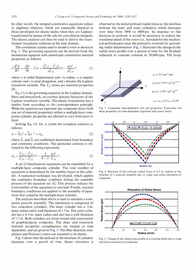
Fig. 4 shows that the preload at the interface of cylinders
decreases over a period of time. Stress relaxation is
observed in the initial preload (radial stress at the interfacebetween the inner and outer cylinders), which decreasesover time from 5000 to 4000 psi. In response to thisdecrease in preload, it would be necessary to reduce therotational speed of the rotor (i.e., knockdown the mechan-ical performance) since the preload is essential for prevent-
ing radial delamination. Fig. 5 illustrates the change in theradial stress profile over a period of time for the flywheelsubjected to constant rotation at 50,000 rpm. The hoop
3
(t )
(t )
10*7.553=(t)S 0.0175-7
22
10*1.383=(t)S 0.06 -6
66
psi / 105.9=S -8
11 •
0.36 =0.3,== 231312 ν ν ν
2
1
Fig. 3. Composite time-dependent unit ply properties. Transverse andshear properties are time-dependent expressed with power forms.
Infinite10 yrsInitia
3.5
-5.0E+03
-4.0E+03
-3.0E+03
-2.0E+03
-1.0E+03
0.0E+003 4 4.5 5 5.5 6
R a d i a l S t r e s s ( p s i )
Radius (in)
Fig. 4. Decrease of the preload (radial stress at 4.5 in. radius) at theinterface of a press-fit assembly due to creep and stress relaxation of composite.
Relaxation of Radial Stress
0.0E+00
2.0E+03
4.0E+03
6.0E+03
8.0E+03
1.0E+04
R a d i a l S t r e s s ( p s i )
Ini tial 10 Years Inf in ite
3.0 3.5 4.0 4.5 5.0 5.5 6.0
Radius (inch)
Fig. 5. Change of the radial stress profile in a rotating wheel due to creep
and stress relaxation of composite.
2522 J. Tzeng et al. / Composites Science and Technology 66 (2006) 2520–2527

7/29/2019 1-s2.0-S0266353806000364-main
http://slidepdf.com/reader/full/1-s20-s0266353806000364-main 4/8
stress profile changes also, as illustrated in Fig. 6. There issignificant redistribution of stresses that should be consid-ered in the design.
3. Material testing
Composite cylinders with an inner diameter of 20 in.were fabricated at the ARL in-house facilities as shownin Fig. 7. The cylinder was made of T1000G graphite/
epoxy composite. Several thin cylinders (0.1 in. thick) werefabricated and sliced into 0.5-in. wide ring specimens forhydro-burst testing. A test matrix was conducted to mea-sure the strength and stiffness of these composite ring spec-imens. This procedure works well for evaluating thecircumferential strength of cylinders fabricated with vari-
ous fiber volume fractions, matrix materials, and fabrica-tion methods. High strength is obtained through carefulengineering and manufacturing of the cylinders. Thestrengths measured from the ring samples are between500 and 600 ksi upon the fabrication methods and materialsystems of rings.
As discussed previously, the performance of compositeflywheel can be enhanced through a proper laminate archi-tecture design with axial reinforcements. A series of testswere performed to evaluate the enhancement of S-2 glassaxial glass reinforcement on the transverse, shear, and frac-ture properties of laminates. Effects of glass ply content onshear strength were evaluated using carbon/glass hybrid
laminates. T1000G composite laminates with various axialglass contents were tested using Iosipescu share tests. Fig. 8shows the trend of the enhancement of shear strength (s23)of T1000G laminate with increasing glass content. Theseresults can be used in the design of laminated compositecylinders. An identical test matrix was also performed fortransverse tensile tests.
Fracture toughness is a critical property for compositeflywheels subjected to a very high operating stress.Micro-cracks developed in the matrix can propagate andcause delamination in the rotor. A composite system withhigh fracture toughness has a slow rate of crack propaga-
tion and, thus, a longer fatigue life. The fracture toughnessof composite cylinders can also be enhanced by addingglass content in the rotor axial direction [5]. Fig. 9 showshow the glass content affects the fracture toughness. Refer-ence [8] gives details of the test method, results, and frac-ture mechanism predicted for composite cylinders. Thedependence of loading rate on the fracture toughness isalso evaluated, which is useful for a high-rate loading con-dition. In conjunction with this study, a fatigue study oncombined shear and compressive loading of compositelaminates was performed in Ref. [9].
4. Rotor testing: vibration and strain measurement
Several techniques exist for measuring strains in therotors of flywheels during operation, including ESPI, straingages with slip rings or telemetry, X-ray diffraction, andoptoelectronic strain measurement (OESM). The OESMtechnique, described in detail [10,11], is capable of simulta-neously measuring and isolating flexible-body displace-ments (strain) and rigid-body displacements (vibration) ina non-contact fashion on flywheels rotating at several tensof thousands of rpm. As well, the computer control of theOESM sensor enables the displacements to be measured ina quasi-continuous fashion (i.e., without post-processing),
and the OESM technique includes built-in compensation
Fig. 7. Twenty inch diameter composite cylinders fabricated at ARL
facilities.
Relaxation of Hoop Stress
7.00E+04
7.50E+04
8.00E+04
8.50E+04
9.00E+04
9.50E+04
1.00E+05
1.05E+05
3.0 3.5 4.0 4.5 5.0 5.5 6.0
Radius (inch)
H o o p
S t r e s s ( p s i )
Ini tial 10 Years Inf in ite
Fig. 6. Change of the hoop stress profile in a rotating wheel due to creepand stress relaxation of composite.
J. Tzeng et al. / Composites Science and Technology 66 (2006) 2520–2527 2523

7/29/2019 1-s2.0-S0266353806000364-main
http://slidepdf.com/reader/full/1-s20-s0266353806000364-main 5/8
for drift/aging of the sensor. The combination of theseabove-mentioned features, as well as its compact size,makes the OESM technique suitable for long-term autono-mous operation in the field.
The OESM technique consists of two components; areflective pattern applied to the axial face of the flywheel,and a sensor that ‘‘looks at’’ the pattern as the flywheelrotates. The OESM sensor projects a stationary spot of
light onto the axial face of a rotating disk. The reflectivepattern on the axial face of the disk modulates the reflectiv-ity of the light spot. This pattern, which deforms in unisonwith the disk, is designed such that the in-plane displace-ment of the disk is effectively ‘‘encoded’’ into a stream of reflected pulses of light. A photodetector on the sensor con-verts this stream of reflected light pulses to electrical pulsesand sends these electrical pulses to the gate of a timer/counter circuit in a digital computer. The computer usesa tachometer signal to convert the (temporal) pulse widthsto angular widths of the reflective features of the pattern.Fig. 10 shows an illustration of a rotor with inner and outerradii, ri and ro, respectively, with a pattern that has one
reflective patch (the cardioid shape shown in white). Alsoshown in Fig. 10 is the corresponding swept-angle, or so-called duty cycle, output from the sensor.
The instantaneous displacement, u, of the rotor at thelocation of the projected spot of light is determined bycomparing the instantaneously measured angular widthsto a calibration record of pulse-width-versus-radial-loca-tion on the rotor. Fig. 11 shows the duty cycle before defor-mation, /1, and after deformation, /2, for a sensor fixed inspace at a location corresponding to an initial radial loca-tion r1 on the undeformed rotor.
1 T1000
3Glass
gage section
2 S2-Glass
mean S.D. mean S.D. mean S.D. mean S.D.
0 12.72 0.51 1.78 0.22 4.88 0.38 0.91 0.10
7 12.65 0.39 1.5 0.08 7.2 0.51 1.18 0.08
10 12.71 0.41 1.68 0.12 8.67 0.24 0.93 0.13
G2-3 (Msi)%
S2-glass
τ1-3 (ksi)
G1-3 (Msi) τ2-3 (ksi)
Fig. 8. Iosipescu test specimen represents the loading condition and rotor construction. Shear strength increases as the glass content increases.
0
1000
2000
3000
4000
5000
6000
0 1 2 3 4 5 6
l o a d
( N )
displacement (mm)
12% v.c.
6% v.c.
S2-Glass
IM7
Fig. 9. Fracture increases as the glass fiber content increases in the
composite laminate. The glass is oriented to arrest the crack propagation.
φ
r i
r o
fixedsensor
sensor
path
Top view
Oblique view
0 π 2π
LogicSignal
on
off
ρ /2
ρ
5ρ /2
Duty Cycle
spot of
light Azimuthal location
Fig. 10. Illustration of a pattern and sensor configuration with corresponding duty cycle [10].
2524 J. Tzeng et al. / Composites Science and Technology 66 (2006) 2520–2527

7/29/2019 1-s2.0-S0266353806000364-main
http://slidepdf.com/reader/full/1-s20-s0266353806000364-main 6/8
4.1. Improvements to ARL OESM system
Recent changes have been made to many aspects of theOESM system described. These changes encompassimprovements to the pattern shape; the technique forapplying the pattern to the rotor; the sensor geometry; con-figuration and control of the sensor.
4.1.1. Pattern shape
While the shape of the pattern shown in Figs. 10 and 11is a spiral boundary shape [10,11], the pattern shape used inpractice possessed geometric features with linear bound-aries. Fig. 12 shows a comparison of these two types of pat-
tern shapes on an identical annular rotor. Note that thepatterns shown in Fig. 12 possess four reflective lobes,while the patterns shown in Figs. 10 and 11 had only onelobe (for illustrative purposes) (see Fig. 13).
A linear boundary pattern possesses a region near theinner radius where the duty cycle exhibits a large changewith respect to radial position. This large change corre-sponds to a large ‘‘slope’’ of the calibration record and,therefore, is a pattern with favorable sensitivity to radial
ur 1= r 1 r 2
before
deformation:
after
deformation:
φ 1
φ 2
2π
0r i r 2 r 1 r o
φ 2
φ 1
r
Duty
Cycle,
φ
radial position
Calibration Record of φ (r )
Fig. 11. Illustration of change in duty cycle at one radial location before and after deformation [10].
0
0.4
0.8
1.2
1.6
0.7 0.8 0.9 1
Normalized Radius, r / r o
DutyCycle,
φ
(rad)
Linear BoundarySpiral Boundary
Calibration Records for Linear Boundary andSpiral Boundary Patterns
r i
r o
r i
r o
lobe Linear boundary
Spiral boundary
Fig. 12. Illustration of a four-lobe linear boundary and four-lobe spiral boundary pattern.
Acrylicvacuum
enclosure
Optoelectronicsensor
Glasswindow
Rotor with newreflectivepattern
Fig. 13. Picture of the rotor testing facility at ARL.
J. Tzeng et al. / Composites Science and Technology 66 (2006) 2520–2527 2525

7/29/2019 1-s2.0-S0266353806000364-main
http://slidepdf.com/reader/full/1-s20-s0266353806000364-main 7/8
displacement (see Fig. 12). It has been found, however, thatthe portion of the linear boundary pattern near ri (wherethis large slope is an advantage) is not practical to use.In the usable radial locations in a linear boundary pattern,the duty cycle of a spiral boundary pattern exhibits equiv-alent or better sensitivity to radial displacement than a lin-
ear boundary pattern. The sensitivity of a linear boundarypattern quickly decays away from the inner radius whilethe sensitivity of a spiral boundary pattern remains essen-tially constant over the entire radial region. Based on thesefindings, the current rotor testing protocol employs a spiralboundary reflective pattern.
4.1.2. Pattern application
The reflective pattern in the OESM system is essentiallyanalogous to a strain gage inasmuch as the pattern mustnot significantly reinforce the rotor and it must deformwith the rotor. With the previous OESM technique, thepattern was applied to the axial face of the rotor with a
spray-on photographic emulsion. The emulsion was devel-oped in a contact-print fashion using a mask with com-puter-generated geometric features. The main drawbacksof this pattern application technique are that it is verylaborious, and it results in a delicate pattern. The newtechnique for applying the reflective pattern uses a thinlayer of reflective paint followed directly by a thin layerof ink that is applied using a pen and compass. Theresulting pattern is able to be applied faster and is muchmore resistant to damage that may occur during handlingof the rotor.
4.1.3. Sensor geometryDuring testing of the original OESM system it was
found that when the vertical distance between the rotorand the sensor changed more than about 50 lm, significanterrors were introduced in the measurement of the apparentduty cycle. It is believed that some of this sensitivity wasattributable to drifting of the spot out of the active areaof the photodetector, as the original OESM sensor pro- jected the spot of light onto the rotor surface at an anglethat was approximately ten degrees away from perpendic-ular. Also, the original sensor had a standoff distancebetween the sensor and the rotor surface of approximately4.5 mm, thus vertical displacements resulted in de-focusingof the projected spot. With these design issues in mind, thecurrent OESM sensor has a standoff distance of approxi-mately 50 mm, and projects the light perpendicularly tothe surface.
4.1.4. Configuration and control of the sensor
The OESM system described in [10,11] was configuredwith ten positions – equally spaced along a radial line – at which a sensor could be located. The sensors in thisconfiguration remained stationary during operation. Thedisplacements measured at these 10 locations, therefore,were only useful for constructing a rather coarse full-field
‘‘picture’’ of the state of strain in the rotor. The current
OESM setup uses a single sensor, which is bolted to a linearstepper motor stage. The stroke length of this linear stage iscapable of scanning a large radial range (125 mm) in radialincrements as small as 1 lm, thus enabling the constructionof a very fine full-field ‘‘picture’’ of the state of strain in therotor. As well, a new algorithm for controlling the inevita-
ble drift of the sensor [12] will be employed in the currentOESM system at ARL.
4.1.5. OESM system at ARL
Measurement of radial growth is an essential piece of data for validating the structural design and analysis of the flywheel rotor. It is unlikely that any rotor will beaccepted for operation in the field without validation bytesting. The previously developed OESM technique wascapable of measuring displacements with 1-lm sensitivityon a disk rotating at 20 krpm. While not yet fully tested,the improvements embodied in the current OESM systemas described above should enable a several-fold increase
in the sensitivity to displacement. Fig. 4 shows a pictureof the spin test facility at ARL, which is ready to be usedin the component tests in support of the efforts for develop-ing a pulsed power rotating machine.
5. Conclusion
A comprehensive research program has been conductedto develop high performance composite flywheels forenergy storage applications. Modeling techniques includingelastic, viscoelastic, and fatigue analyses were developedfor design as well as prediction of rotor behaviors. A lam-
inate architecture for achieving high mechanical perfor-mance flywheels was proposed based on lessons learnedfrom previous programs. A material test matrix at the lam-inate level was also proposed from a design point view of high performance flywheels. The optical strain measure-ment technique can be used to validate flywheel designand construction. Particularly, the proposed design andtest procedure indeed considers the long-term behavior of flywheel, such as creep, stress relaxation, fatigue, and frac-ture of composites.
References
[1] Stone RG. ‘‘Fiber-composite flywheel program: quarterly progressreport,’’ UCRL-50033-76-4, Lawrence Livermore National Labora-tory, December 1976.
[2] Pardoen RD, Nudenberg, Wartout BE. Achieving desirable stressstates in thick rim rotating disks by variation of properties. In:Proceedings of 1980 flywheel technology symposium, 159 October1980.
[3] Acebal R. Energy Storage capabilities of rotating machines includinga comparison of laminated disk and rim rotor design. IEEE TransMagnetics 1999;35(1).
[4] Tzeng JT, Chien LS. A thermal/mechanical model of axially loadedthick-walled composite cylinders. J Compos Eng 1994;4(2).
[5] Tzeng JT, Moy P. Composite rotor design for fatigue crack growthresistance. In: Proceedings of the 16th technical conference, american
society for composites, September 2001.
2526 J. Tzeng et al. / Composites Science and Technology 66 (2006) 2520–2527

7/29/2019 1-s2.0-S0266353806000364-main
http://slidepdf.com/reader/full/1-s20-s0266353806000364-main 8/8
[6] Tzeng JT. Viscoelastic analysis of composite cylinder subject torotation. J Compos Mater 2002;36(2):229–39.
[7] Tzeng JT. Viscoelastic modeling of press-fitted composite cylinders. JCompos Technol Res 2001;23(1):21–7.
[8] Moy P, Tzeng JT. Loading rate effect on translaminar fracturetoughness of hybrid composite laminates, dynamic failure in com-posite materials and structures, AMD-vol. 243, ASME internationalmechanical engineering congress and exposition, November 5–7,2000.
[9] DeTeresa SJ, Allison LM, Freeman DC, Groves SE. Matrix-dominated performance of thick-section fiber composite for flywheel
applications. In: Proceedings of SAMPE technical conference, LongBeach, CA, May 2001.
[10] Emerson RP. Viscoelastic flywheel rotors: modeling and measure-ment, Ph.D. dissertation, The Pennsylvania State University, Uni-versity Park, PA, December 2002.
[11] Emerson RP, Bakis CE. Optoelectronic strain measurement forflywheels. Exp Mech 2002;42:237–46.
[12] Bakis CE, Haldeman BJ, Emerson RP. Optoelectronic radialdisplacement measurement method for rotating disks. In: GdoutosEE, editor. Recent Adv Exp Mech. New York: Kluwer AcademicPublishers; 2002. p. 315–24.
J. Tzeng et al. / Composites Science and Technology 66 (2006) 2520–2527 2527


