Embed Size (px)
DESCRIPTION
Zabi 141021065232 Conversion Gate01
Citation preview

7172019 1-s20-S0143974X13000308-main
httpslidepdfcomreaderfull1-s20-s0143974x13000308-main 110
Fire behavior of eccentrically loaded slender high strengthconcrete-1047297lled tubular columns
V Moliner a A Espinos b ML Romero b A Hospitaler b
a Centro Teacutecnico del Fuego (CTF) AIDICO Valencia Spainb Instituto de Ciencia y Tecnologiacutea del Hormigoacuten (ICITECH) Universitat Politegravecnica de Valegravencia Spain
a b s t r a c ta r t i c l e i n f o
Article history
Received 22 November 2012Accepted 24 January 2013
Available online 28 February 2013
Keywords
Fire resistance
Composite column
Concrete-1047297lled tubular column
High strength concrete
Eccentric axial load
This paper describes a series of 24 1047297re tests conducted on slender circular hollow section columns 1047297lled with
normal and high strength concrete subjected to eccentric axial load It is a continuation of a previous re-
search paper (Romero et al 2011 [1]) where test results on centrally loaded columns were presented The
test parameters covered in this 1047297re testing program were the nominal strength of concrete (30 and
90 MPa) the in1047297lling type (plain bar-reinforced and steel 1047297ber reinforced concrete) the axial load level
(20 and 40) and the load eccentricity (20 and 50 mm) The columns were tested under 1047297xed-pinned
boundary conditions with a relative slenderness at room temperature higher than 05 for all the specimens
The aim of this paper is to study the in1047298uence of eccentricity in combination with the type of concrete in1047297ll
The results show that the addition of steel 1047297bers does not improve the 1047297re resistance of slender columns
under eccentric loads as compared to columns 1047297lled with plain concrete However the addition of
reinforcing bars increases the 1047297re resistance of the columns in this situation Filling the steel hollow section
columns with concrete increases their 1047297re resistance the increase in load bearing capacity being more notice-
able for columns 1047297lled with high strength concrete A comparison with the current simple calculation model
in Eurocode 4 Part 12 shows that although the method is safe for eccentrically loaded columns it produces a
high error in the predictions for columns 1047297lled with plain or steel 1047297ber reinforced concrete
copy 2013 Elsevier Ltd All rights reserved
1 Introduction
Concrete 1047297lled tubular (CFT) columns make use of the combined
action of steel and concrete showing an ideal structural performance
While the steel tube con1047297nes the concrete core enhancing its com-
pressive strength the concrete core prevents the steel tube wall
from local buckling In addition CFT columns can reach high 1047297re resis-
tance times without the need of external protection [23]
Although the 1047297re resistance of CFT columns subjected to concen-
tric axial loads has been widely studied through experimental testing
in the framework of the research projects from the National Research
Council of Canada (NRCC) [4ndash6] the Comiteacute International pour le
Deacuteveloppement et lEtude de la Construction Tubulaire (CIDECT)
[78] or the previous experimental program from the authors of this
paper [1] the effect of eccentricity needs further evaluation being a
situation which can be commonly found in practice
Some of the main 1047297re testing programs carried out worldwide
have taken the load eccentricity into account (Lie and Chabot [4]
Grandjean et al [7] Kordina and Klingsch [8]) but using only a limit-
ed number of column specimens
A speci1047297c 1047297re testing program focusing on eccentrically loaded CFT
columns was carried out at the Centre Technique Industriel de la
Construction Meacutetallique (CTICM) France in the framework of CIDECT
research project 15R [9] in order to validate the work on the develop-
ment of a simpli1047297ed calculation method for eccentrically loaded col-
umns undertaken within the CIDECT project 15Q [10] Four columns
were tested under large eccentricities (eD=075 and 15) two of
them of circular section and another two of square shape All columns
were 1047297lled with bar-reinforced normal strength concrete Nevertheless
the results of this 1047297re testing program are limited and need to be
extended
Some tests were also carried out in Tianjin (China) by the research
group headed by Han [11] on CFT columns considering eccentric loads
In this program 13 columns of circular section were tested four of
them subjected to eccentric load The parameters investigated were
the diameter of the cross-section the steel tube wall thickness the 1047297re
protection coat thickness and the load eccentricity ratio (eD=0ndash03)
Lu et al [12] carried out a series of 1047297re tests at Monash University
(Australia) on high strength self-consolidating concrete 1047297lled steel tu-
bular stub columns taking into account the eccentricity of the load Six
square section columns were tested two of them under eccentric load
The difference of the 1047297re testing program presented in this paper
compared with the similar experimentalstudies carried out by other re-
searchers previously mentioned is that it focuses on slender columns
Journal of Constructional Steel Research 83 (2013) 137ndash146
Corresponding author Tel +34 963877007x76742 fax +34 963879679
E-mail address mromeromesupves (ML Romero)
0143-974X$ ndash see front matter copy 2013 Elsevier Ltd All rights reserved
httpdxdoiorg101016jjcsr201301011
Contents lists available at SciVerse ScienceDirect
Journal of Constructional Steel Research
7172019 1-s20-S0143974X13000308-main
httpslidepdfcomreaderfull1-s20-s0143974x13000308-main 210
with the relative slenderness of all the specimens above 05 Moreover
this experimental program investigates the effectof using high strength
concrete (HSC) and different types of reinforcement such as steel1047297bers
or reinforcing bars in combination with eccentricity
In the previous work [1] the authors of this paper presented the
results of 16 1047297re tests conducted on slender circular hollow section
columns 1047297lled with normal and high strength concrete subjected to
concentric axial load These experiments focused on the use of normaland high strength concrete as in1047297ll slender columns and different
types of reinforcement (reinforcing bars or steel 1047297bers) The authors
concluded that in slender columns the utilization of reinforcing bars
was more useful for the case of HSC than for NSC While Schaumann
et al [13] reported that the 1047297re resistance of HSC 1047297lled hollow section
columns can be signi1047297cantly enhanced by using steel 1047297bers as rein-
forcement the authors did not found an improvement in the 1047297re re-
sistance for the range of slender columns investigated
Besides the study evidenced some limitations in the Eurocode 4
Part 12 [14] simple calculation model when predicting the axial
buckling load of slender concrete 1047297lled steel hollow section columns
at elevated temperatures for both NSC and HSC
In this paper the results from a new experimental programon slen-
der eccentrically loaded CFT columnsexposed to 1047297re are presented Thein1047298uence of parameters such as the concrete compressive strength
(30 MPa and 90 MPa) the type of reinforcement (plain concrete
bar-reinforced concrete and steel 1047297ber reinforced concrete) the load
level (20 and 40) and the load eccentricity (20 mm and 50 mm)
are analyzed The 1047297nal aim of this investigation is to verify the accuracy
of the current calculation method in Eurocode 4 Part 12 [14] for eccen-
tric loads as it was previously found through numerical simulations
[15] that under eccentric loads this method provides very conservative
results with a high error in thepredictions By means of theresults from
this 1047297re testing program the current provisions of Eurocode 4 Part 12
[14] for eccentrically loaded columns are studied and the Fire Concrete
Contribution Ratio (FCCR) previously de1047297ned in [1] is obtained which
helps to quantify the importance of the use of concrete in1047297lling in hol-
low steel section columns exposed to 1047297re
2 Experimental program
In this new experimental program 241047297re tests were carried out on
normal and high strength concrete-1047297lled steel tubular slender col-
umns under eccentric loads with eccentricities of 20 and 50 mm
The aim of this research was to investigate the effect of four main pa-
rameters on the1047297re behavior of these columns concrete strength ( f c)
type of concrete in1047297lling (plain bar-reinforced and steel 1047297ber
reinforced concrete) load level ( μ =N N Rd) and load eccentricity(e) The test values of these parameters were selected according to
the regular practice in construction All the tested columns were
3180 mm long and had an outer diameter of 159 mm The steel
tubes had a wall thickness of 6 mm therefore the Dt ratio was con-
stant for all the columns Those values were chosen in order to obtain
slender columns at the same time avoiding local buckling The steel
yield strength was kept constant using S275JR grade ( f y=275 MPa)
for all the steel tubes With regard to the nominal strength of con-
crete the specimens were 1047297lled with concrete mixes of 30 MPa
(NSC) and 90 MPa (HSC) In all the tests the applied load (N ) was cal-
culated as a percentage of the corresponding ultimate load at room
temperature (N Rd) which was obtained by means of a validated nu-
merical model developed by Lacuesta et al [16] Again according to
the common load levels found in practice values of μ =02 and 04
were adopted The columns were tested under pinnedndash1047297xed (PndashF)
boundary conditions The tested specimens with their properties
and resulting 1047297re resistance ratings (FRR) are listed in Table 1
All of the tests were performed in the 1047297re resistance laboratory of
AIDICO (Instituto Tecnoloacutegico de la Construccioacuten) in Valencia Spain
The tests specimens can be identi1047297ed as follows NXXX-T-L-FF-
EE-AA (eg C159-6-3-30-50-20) where N stands for type of concrete
(C= plain concrete RC= bar-reinforced concrete and FC =steel 1047297ber
reinforced concrete) XXX is the steel tube outer nominal diameter in
millimeters T the steel tube wall thickness in millimeters L the nom-
inal length of the column in meters FF the nominal concrete strength
in MPa EE the load eccentricity in millimeters and AA the load level
expressed as a percentage of the maximum capacity of the column
at room temperature
21 Steel
Cold formed circular steel hollow sections were used in the experi-
mentalprogramwith an outer diameter of 159 mm anda wall thickness
of 6 mm The steel grade was S275JR ( f y=275 MPa) nevertheless the
real yield strength of the empty tubes was obtained by performing the
corresponding coupon test (see Table 1) The mean value of the steel
modulus of elasticity was 210 GPa according to European standards
22 Concrete
As mentioned above the experimental program made use of con-crete mixtures of normal ( f c=30 MPa) and high strength concrete
( f c=90 MPa) both for plain reinforced and steel 1047297ber reinforced
concretes The type of aggregates was calcareous in all cases
In order to determine the compressive strength of concrete sets of
concrete cylinders were also prepared and cured in standard condi-
tions during 28 days All cylinder samples were tested on the same
date as the column 1047297re test The cylinder compressive strength ( f c)
of all the tested specimens can be found in Table 1
In order to measure the concrete moisture content cubic speci-
mens of 150times150times150 mm were also prepared The moisture con-
tent was determined according to the procedure described in EN
1363-1 [17] The weight of each sample was measured before and
after drying them in a small oven at 150 degC and the moisture level
was obtained accordingly
Notation
C plain concrete
CFT concrete 1047297lled tube
D diameter of the column
e loading eccentricity
EC4 Eurocode 4 Part 1ndash2 (EN 1994-1-2)
FC steel 1047297ber reinforced concrete
FCCR 1047297re concrete contribution ratio
FRR 1047297re resistance rating
f c compressive cylinder strength of concrete at room
temperature (test date)
f s yield strength of reinforcing steel at room temperature
f y yield strength of structural steel at room temperature
HSC high strength concrete
L length of the column
N test load
N 1047297Rd design axial buckling load of the column in the 1047297re
situation
N Rd resistance of the column in axial compression at room
temperature
NSC normal strength concrete
RC bar-reinforced concrete
t thickness of the steel tube
μ =N N Rd axial load level
λ relative slenderness at room temperature
138 V Moliner et al Journal of Constructional Steel Research 83 (2013) 137 ndash146
7172019 1-s20-S0143974X13000308-main
httpslidepdfcomreaderfull1-s20-s0143974x13000308-main 310
23 Specimens
The length of the columns was 3180 mm although only 3000 mm
was directly exposed to the 1047297re inside the furnace For each column
specimen two ventilation holes of 15 mm diameter were drilled in
the wall of the steel hollow section and located at 100 mm from
each column end as proposed by Lie and Chabot [4] All the columns
had a relative slenderness at room temperature (λ) higher than 05
(see Table 1) The relative slenderness of the columns was calculated
according to Eurocode 4 Part 11 [18]
λ frac14
ffiffiffiffiffiffiffiN pl
N cr
s frac14
ffiffiffiffiffiffiffiffiffiffi ffiffiffiffiffiffiffiffiffiffiffi ffiffiffiffiffi Ac f c thorn As f y
π 2E I L2
v uut eth1THORN
where E I =E s I s+06 E cm I c I s and I c are the second moment of inertia
of the steel tube and the concrete core respectively E s is the modulus
of elasticity of steel and E cm is the secant modulus of elasticity of con-
crete Ac is the cross-sectional area of concrete and As is the
cross-sectional area of steel reinforcement
A 300times 300times 15 mm steel plate was welded to the top and bottom
end of the columns the top end plate being welded after concrete
casting was 1047297nished Concrete was poured with the columns placed
in vertical position and afterwards shaken with a needle vibratorThe reinforced specimens (RC) followed the arrangementpresented
in Fig 1c with four longitudinal reinforcing bars of 12 mm diameter
and 6 mm stirrups with 30 cm spacing along the column length The
geometrical reinforcement ratio ( As Ac) was equal to 267 The theo-
retical yield strength of the reinforcing steel ( f s) was 500 MPa
The steel 1047297ber reinforced specimens (FC) used a proportion of
40 kgm3 high strength Dramix 4060 steel 1047297bers
24 Temperature measurement
In order to register the temperature evolution within the cross-
section during the 1047297re test a set of 1047297ve type K thermocouples (TC1
to TC5) was positioned in the mid-length section of the column fol-
lowing the arrangement in Fig 1b While thermocouple number 1
was welded to the steel tube surface the other 4 thermocouples
were embedded in the concrete core
25 Test set up and procedure
The tests were carried out in a 5times 3 m horizontal furnace
equipped with a hydraulic jack of 1000 kN maximum capacity
Fig 2 There were 16 natural gas burners in the furnace chamber ar-
ranged in two horizontal rows containing 8 burners each located atmid-height of the chamber The columns were placed vertically inside
the furnace Fig 3a 1047297xed (F) at the bottom end Fig 3d and pinned
(P) at the top end Fig 3c
Once the load was applied it was kept constant and the burners
were then activated following the standard ISO 834 1047297re curve [19]
with unrestrained axial elongation The temperature inside the fur-
nace was automatically registered and controlled by 6 thermocouples
(plate thermometer) and a pressure sensor inside the furnace cham-
ber The axial elongation at the top end of the columns was measured
by means of a LVDT located outside the furnace
3 Test results
The evolution of the axial displacement at the top end of the col-umn along the 1047297re exposure time for the tested columns is plotted
in Figs 4 to 6 The resulting 1047297re resistance rating (FRR) values
obtained according to EN 1363-1 [17] are listed in Table 1 As it was
previously found by the authors in previous work [1] on concentrical-
ly loaded columns it can be seen that for slender columns subjected
to eccentric loads the FRR obtained is generally reduced compared
to stub columns particularly in those cases subjected to a high axial
load level ( μ =04) where the FRR was always lower than 30 min
It is worth noting that all the specimens tested were unprotected
Nevertheless those cases with a low axial load level ( μ =02)
presented FRR values over 30 min (except for tests 19 and 23
which made use of steel 1047297ber reinforced high strength concrete)
As expected for a certain type of concrete 1047297lling and concrete
nominal strength as the load eccentricity was increased the 1047297re
Table 1
Test properties and results
No Name f c(MPa)
f y(MPa)
e
(mm)
eD μ
()
λ N
(kN)
FRR
(min)
1 C159-6-3-30-20-20 3583 33203 20 0126 20 060 1690 32
2 C159-6-3-30-20-40 4217 33203 20 0126 40 061 3370 16
3 C159-6-3-90-20-20 7370 33203 20 0126 20 069 2720 34
4 C159-6-3-90-20-40 7464 34363 20 0126 40 070 5440 11
5 C159-6-3-30-50-20 3050 34363 50 0314 20 059 1264 29
6 C159-6-3-30-50-40 3825 36565 50 0314 40 062 2528 237 C159-6-3-90-50-20 7913 36565 50 0314 20 072 1940 30
8 C159-6-3-90-50-40 9832 36565 50 0314 40 076 3880 16
9 RC159-6-3-30-20-20 3900 35722 20 0126 20 065 1800 47
10 RC159-6-3-30-20-40 4038 35722 20 0126 40 065 3600 24
11 RC159-6-3-90-20-20 9367 35722 20 0126 20 076 2638 48
12 RC159-6-3-90-20-40 9600 38638 20 0126 40 078 5277 22
13 RC159-6-3-30-50-20 3100 38638 50 0314 20 064 1400 39
14 RC159-6-3-30-50-40 3950 38638 50 0314 40 066 2799 20
15 RC159-6-3-90-50-20 9297 31522 50 0314 20 075 2037 40
16 RC159-6-3-90-50-40 9187 31522 50 0314 40 074 4074 15
17 FC159-6-3-30-20-20 3467 31522 20 0126 20 058 1686 30
18 FC159-6-3-30-20-40 3150 33777 20 0126 40 059 3373 16
19 FC159-6-3-90-20-20 8712 33777 20 0126 20 072 2720 23
20 FC159-6-3-90-20-40 8304 33777 20 0126 40 071 5440 13
21 FC159-6-3-30-50-20 3300 31864 50 0314 20 058 1264 30
22 FC159-6-3-30-50-40 3765 31864 50 0314 40 059 2528 19
23 FC159-6-3-90-50-20 9699 31864 50 0314 20 074 1939 2924 FC159-6-3-90-50-40 9278 32639 50 0314 40 073 3878 14
Where C stands forplain concrete RC forbar-reinforcedconcrete andFC forsteel1047297berreinforcedconcrete All the specimens in thistable withD=159 mm t =6 mm L=3180 mmand
tested under pinnedndash1047297xed (PndashF) boundary conditions
139V Moliner et al Journal of Constructional Steel Research 83 (2013) 137 ndash146
7172019 1-s20-S0143974X13000308-main
httpslidepdfcomreaderfull1-s20-s0143974x13000308-main 410
Fig 1 Schematic view of the 1047297re test a) test setup b) thermocouple location c) reinforcement arrangement
b
a
c
d
e
f
Fig 2 General view of the testing facilities a) test furnace b) furnace access gate c) loading frame d) temperature data acquisition system e) hydraulic loading system f) load
data acquisition system
140 V Moliner et al Journal of Constructional Steel Research 83 (2013) 137 ndash146
7172019 1-s20-S0143974X13000308-main
httpslidepdfcomreaderfull1-s20-s0143974x13000308-main 510
resistance time decreased except in those cases where the moisture
content or the real concrete strength was found higher in the speci-
men with the higher eccentricity producing the opposite effect (see
tests 2ndash6 and 4ndash8)
The 1047297re resistance of the HSC specimens resulted lower than that of
the NSC specimens for the higher load levels ( μ =04) where in most
cases the failure occurred before the load was transferred to the con-
crete core thus not taking advantage of its contribution to sustain theapplied load Nevertheless for the smaller load levels ( μ =02) the dif-
ference was not so clear the HSC specimens producing the same or
higher 1047297re resistance times with a higher axial load applied in terms
of absolute values(except fortests 17 and 19) Therefore formoderated
loadlevels theuseof HSC isbene1047297cial since it increases theload bearing
capacity of the column for a certain 1047297re exposure time
From Figs 4 and 5 it can be inferred that the addition of reinforcing
bars produced a bene1047297t in the 1047297re resistance helping in some cases to
avoid a premature failure of the column (see tests 10 and 12 versus 2
and 4) since the reinforcing bars improved the resistance of the con-
crete areas into tension allowing the concrete core to sustain the load
for a certain time This conclusion can be seen with more clarity in
Fig 7 where the in1047298uence of the type of reinforcement for columns
1047297lled with HSC and subjected to a 50 mm load eccentricity with a 20axial load ratio is analyzed
From Fig 7 it becomes clear that no special bene1047297t in the 1047297re re-
sistance is obtained through the addition of steel 1047297bers This 1047297nding is
in opposition with the conclusions drawn by Schaumann et al [13]
who found that the 1047297re resistance of HSC 1047297lled tubular columns can
be improved by means of the addition of steel 1047297bers The difference
is due to the higher slenderness of the columns tested in this experi-
mental program which is higher than 05 for all the specimens (see
Table 1) while the slenderness of the Canadian specimens [6] used
for comparison by Schaumann et al [13] was more reduced therefore
making possible to gain advantage of the addition of steel 1047297bers
Regarding the use of high strength concrete no particularities
were encountered in the corresponding 1047297re tests without 1047297nding
any evidences of the phenomenon of spalling since in this type of
columns the concrete core is protected from a direct 1047297re exposure
by means of the steel tube
The in1047298uence of the load eccentricity is shown in Fig 8 for col-
umns 1047297lled with plain concrete and subjected to a 20 axial load
level In this 1047297gure the results from the present experimental pro-
gram for the two types of concrete studied (NSC and HSC) have
been combined with those presented in the previous paper [1] for
the corresponding concentrically loaded columns As can be seenfor both normal and high strength concrete as the load eccentricity
is increased the resulting 1047297re resistance time decreases Although
the 1047297re resistance of the HSC 1047297lled specimens results similar or
lower than their NSC 1047297lled counterparts for a certain eccentricity
and a 1047297xed load level it is worth mentioning that the HSC 1047297lled spec-
imens are subjected to a higher axial load with an increase in the ap-
plied load as compared to that of the NSC 1047297lled specimens of a 69 for
the column subjected to concentric axial load a 60 for e =20 mm
and a 53 for e =50 mm Therefore the use of HSC as in1047297ll is bene1047297-
cial for all the eccentricities analyzed although the increment
obtained in the load bearing capacity of the columns decreases as
the load eccentricity increases
4 Comparison with Eurocode 4
In this section the test results will be employed to study and dis-
cuss the current provisions of EN 1994-1-2 (EC4) [14] Clause 4351
of this standard presents a general simple calculation model for com-
posite columns which provides a method for calculating the design
value of the buckling resistance of columns subjected to concentric
axial loads in the 1047297re situation Nevertheless as the values of the re-
duction coef 1047297cients to account for the effect of the thermal stresses
are not speci1047297ed in the code for CFT columns a common approach
in practice is to take them as equal to unity [20] More details on
the discussion of the calculation method in EC4 can be found in pre-
vious papers from the authors [2122] as well as other investigations
from Renaud et al [10]
a b
c
d
Fig 3 Details of the 1047297re test a) column before test b) column after failure c) pinned support with eccentricity d) 1047297xed support
141V Moliner et al Journal of Constructional Steel Research 83 (2013) 137 ndash146
7172019 1-s20-S0143974X13000308-main
httpslidepdfcomreaderfull1-s20-s0143974x13000308-main 610
As themethod is valid forconcentric axial loads thebuckling resis-
tance of the columns analyzed in this paper will be obtained as if they
were concentrically loaded and afterwards the resulting buckling
loads will be corrected by means of two coef 1047297cients given in 1047297gures
H1 and H2 from Annex H of EC4 inorder to obtainthe corresponding
buckling resistance of the columns under eccentric loads The 1047297rst co-
ef 1047297cient φ s is a function of the percentage of reinforcement and the
second coef 1047297cientφ δ is a function of the eccentricityand theslender-ness of the column These graphs are not presented in this paper for
simplicity but the effect is to reduce the buckling resistance as the
percentage of reinforcement decreases and the eccentricity increases
The test results were compared with the predictions from EC4 sim-
ple calculation model in terms of the axial buckling load at the time of
failure For that purpose the cross-sectional temperature 1047297eld at the
time of test failure was previously obtained for all the columns using
the measured temperatures at the locations of the 1047297ve thermocouples
(TC1 to TC5) and afterwards the buckling resistance was obtained
with the procedure described in Clause 4351 of EC4 with the correc-
tion described above for taking into account the eccentricity of the load
The bucklingresistance of all thetested columns at thetime of failure
was calculated by means of this method and summarized in Table 2
where the analyzed cases have been divided into two categories
columns using reinforcing bars (RC) and columns which did not use
this type of reinforcement (C and FC) The errors were computed as
the test value divided by theEC4 prediction It wasfound that the simple
calculation model in EC4 produced safe results on average differently
from the results obtained previously for concentrically loaded slender
columns [1] for which the method in EC4 produced unsafe results
As can be seen in Table 2 and Fig 9 the mean error value was 100
for bar-reinforced columns (RC) and the standard deviation 012which proves that the code produces very accurate results for eccen-
trically loaded slender bar-reinforced columns
On the other hand for columns which do not make use of
reinforcing bars (ie columns 1047297lled with plain concrete C or steel
1047297ber reinforced concrete FC) the mean error value was 212 and
the standard deviation 032 thus despite the simple calculation
model provides safe predictions in these cases it results excessively
conservative with a mean safety factor greater than 2
In general it can be concluded that for eccentrically loaded slender
columns the method in Eurocode 4 Part 12 leads to safe results Al-
though the simple calculation model produces very accurate predictions
for bar-reinforced columns this model should be improved for other
types of concrete in1047297ll such as plain concrete or steel 1047297ber reinforced
concrete and its applicability extended to higher concrete grades
0
10
20
30
0 5 10 15 20 25 30 35 40
A x i a l d i s p l a c e m e n t ( m m )
Time (min)
C
e =20mm
a)
micro =04
HSC
micro =04
NSC
micro =02
NSC
micro =02
HSC
-70
-60
-50
-40
-30
-20
-60
-50
-40
-30
-20
-10
-10
0
10
20
30
0 5 10 15 20 25 30 35
A x i a l d i s p l a c e m e n t ( m m )
Time (min)
C159-6-3-30-50-20
C159-6-3-30-50-40
C159-6-3-90-50-20
C159-6-3-90-50-40
C159-6-3-30-20-20
C159-6-3-30-20-40
C159-6-3-90-20-20
C159-6-3-90-20-40
C
e =50mm
b)
micro =04
HSC
micro =04
NSC
micro =02
NSC
micro =02
HSC
Fig 4 Axial displacement versus time curves for eccentrically loaded columns 1047297lled with plain concrete (C) a) e =20 mm b) e =50 mm
142 V Moliner et al Journal of Constructional Steel Research 83 (2013) 137 ndash146
7172019 1-s20-S0143974X13000308-main
httpslidepdfcomreaderfull1-s20-s0143974x13000308-main 710
5 Fire concrete contribution ratio (FCCR)
It was observed in the previous research [1] that the 1047297re resistance
of a steel hollow section column can be increased at least two or three
times by 1047297lling the section with concrete Depending on the applied
load level and the type of concrete in1047297lling the increment obtained
in terms of 1047297re resistance time will be higher or lower
In this section the effect of 1047297lling the columns with concrete isstudied for the case of eccentric axial loads The increment produced
in the 1047297re resistance of the tubular column by means of the concrete
in1047297ll is measured through the so called ldquoFire Concrete Contribution
Ratiordquo (FCCR) which is de1047297ned as the ratio between the 1047297re resis-
tance rating of the concrete 1047297lled column (FRR concrete-1047297lled) and that
of the steel hollow section column (FRR hollow) for a certain value of
the applied axial load
FCCR frac14FRRconcreteminus filled
FRRhollow
eth2THORN
The numerator in this expression can be directly obtained from
the experimental results whereas the denominator is obtained by
means of numerical simulations through a validated 1047297nite element
model developed by the authors [15] The axial load applied to the
hollow section column is the same as that applied to the CFT column
in the corresponding 1047297re test
In Table 3 the values of the 1047297re concrete contribution ratio (FCCR)
obtained for the eccentrically loaded columns are listed representing
the increment which can be obtained in the 1047297re resistance period by
1047297lling the columns with concrete with reference to the 1047297re resistance
of the un1047297lled hollow steel columnsIt can be observed that for all the cases analyzed FCCR values over
15 are obtained meaning that an increment of a 50 or higher in
terms of 1047297re resistance can be obtained by 1047297lling the steel hollow sec-
tion columns with concrete even when eccentricity is applied The
FCCR values result in these cases lower than those obtained for the
concentrically loaded columns [1] with an average value of 230 for
the eccentrically loaded columns versus a 342 for the concentrically
loaded columns
In general the FCCR results higher for the cases subjected to a
lower load level ( μ =02) where the use of the concrete in1047297ll is
more advantageous It is also worth noting that the specimens 1047297lled
with HSC present in most cases a higher FCCR than those 1047297lled with
NSC Although it seemed through the reduced values in 1047297re resistance
time obtained from the tests that the use of HSC was not of great
0
10
20
30
A x i a l d i s p l a c e m e n t ( m m )
Time (min)
RC
e =20mm
a)
micro =04
HSC
micro =04
NSC
micro =02
NSC
micro =02
HSC
0
10
20
30
0 10 20 30 40 50 60
0 5 10 15 20 25 30 35 40 45
A x i a l d i s p l a c e m e n t ( m m )
Time (min)
RC
e =50mm
b)
micro =04
HSC
micro =04
NSC
micro =02
NSC
micro =02
HSC
-70
-60
-50
-40
-30
-20
-10
-70
-60
-50
-40
-30
-20
-10
RC159-6-3-30-20-20
RC159-6-3-30-20-40
RC159-6-3-90-20-20
RC159-6-3-90-20-40
RC159-6-3-30-50-20
RC159-6-3-30-50-40
RC159-6-3-90-50-20RC159-6-3-90-50-40
Fig 5 Axial displacement versus time curves for eccentrically loaded columns 1047297lled with bar-reinforced concrete (RC) a) e =20 mm b) e =50 mm
143V Moliner et al Journal of Constructional Steel Research 83 (2013) 137 ndash146
7172019 1-s20-S0143974X13000308-main
httpslidepdfcomreaderfull1-s20-s0143974x13000308-main 810
0
20
40
A x i a l d i s p l a c e
m e n t ( m m )
Time (min)
FC
e =20mm
a)
micro =04
HSC
micro =04
NSC
micro =02
NSC
micro =02
HSC
0
10
20
30
0 5 10 15 20 25 30 35
0 5 10 15 20 25 30 35
A x i a l d i s p l a c e m e n t ( m m )
Time (min)
FC
e =50mm
b)
micro =04
HSC
micro =04
NSC
micro =02
NSC
micro =02
HSC
-120
-100
-80
-60
-20
-40
-70
-60
-50
-40
-30
-20
-10
FC159-6-3-30-20-20
FC159-6-3-30-20-40
FC159-6-3-90-20-20
FC159-6-3-90-20-40
FC159-6-3-30-50-20
FC159-6-3-30-50-40
FC159-6-3-90-50-20
FC159-6-3-90-50-40
Fig 6 Axial displacement versus time curves for eccentrically loaded columns 1047297lled with steel 1047297ber reinforced concrete (FC) a) e =20 mm b) e =50 mm
0
10
20
30
A x i a l d i s p l a c e m e n t ( m m )
Time (min)
f c=90MPa
e =50mm
=20
0 5 10 15 20 25 30 35 40 45
FC C RC
-70
-60
-50
-40
-30
-20
-10
C159-6-3-30-50-20
RC159-6-3-30-50-40
FC159-6-3-90-50-20
Fig 7 In1047298uence of the type of reinforcement for HSC 1047297lled specimens with 50 mm load eccentricity and subjected to a 20 axial load ratio
144 V Moliner et al Journal of Constructional Steel Research 83 (2013) 137 ndash146
7172019 1-s20-S0143974X13000308-main
httpslidepdfcomreaderfull1-s20-s0143974x13000308-main 910
interest in the 1047297re situation a comparison with the un1047297lled steel hol-
low section columns reveals that using HSC is still of interest since it
allows to increase the load bearing capacity of the column
The addition of steel 1047297bers was not found of a great utility for the
tested eccentrically loaded columns producing similar FCCR values to
those obtained for the columns 1047297lled with plain concrete However
the cases 1047297lled with bar-reinforced concrete presented the highest
FCCR values meaning that the use of reinforcing bars is more effective
to resist eccentric loads in the 1047297re situation
6 Conclusions
In this paper the results of a series of 24 1047297re tests on eccentrically
loaded concrete1047297lledtubularcolumnsof highslendernessare presented
The described tests are a continuation of a previous experimental pro-
gram carried out by the authors on centrally loaded columns [1]
The new experimental program presented in this paper used differ-
ent types of concrete in1047297ll with varying concrete strength (normal and
high strength concrete) and a variety of reinforcement types (plain
bar-reinforced and steel 1047297ber reinforced concrete) The applied load
level and eccentricity were also varied in this 1047297re testing program
Through the results of these tests a series of conclusions on the
1047297re behavior of slender CFT columns subjected to eccentric axial
loads can be drawn For both normal and high strength concrete
the 1047297re resistance time of the columns resulted lower for increasing
values of the load eccentricity
0
10
20
30
0 5 10 15 20 25 30 35 40 45
Time (min)
A x i a l d i s p l a c
e m e n t ( m m )
C
micro=02
HSC HSC
NSC
NSCHSC
NSC
e =50mm
e = 20mm
e =0mm
-70
-60
-50
-40
-30
-20
-10
C159-6-3-30-0-20
C159-6-3-30-20-40
C159-6-3-90-50-20
C159-6-3-90-0-40
C159-6-3-90-20-40
C159-6-3-90-50-40
Fig 8 In1047298uence of the load eccentricity for columns 1047297lled with plain concrete and subjected to a 20 axial load ratio
Table 2
Comparison of the axial buckling load at the time of failure between tests (N test ) andEC4 (N EC4)
No Name N test (kN) N EC4 (kN) N test N EC4
Bar-reinforced columns
9 RC159-6-3-30-20-20 1800 18890 095
10 RC159-6-3-30-20-40 3600 30024 120
11 RC159-6-3-90-20-20 2638 23743 111
12 RC159-6-3-90-20-40 5277 48101 110
13 RC159-6-3-30-50-20 1400 15720 089
14 RC159-6-3-30-50-40 2799 31337 089
15 RC159-6-3-90-50-20 2037 21061 097
16 RC159-6-3-90-50-40 4074 46734 087
Mean 100
Std deviation 012
Columns without reinforcing bars
1 C159-6-3-30-20-20 1690 10232 165
2 C159-6-3-30-20-40 3370 17268 196
3 C159-6-3-90-20-20 2720 11911 228
4 C159-6-3-90-20-40 5440 31785 171
5 C159-6-3-30-50-20 1264 5381 235
6 C159-6-3-30-50-40 2528 8939 283
7 C159-6-3-90-50-20 1940 9399 206
8 C159-6-3-90-50-40 3880 19944 195
17 FC159-6-3-30-20-20 1686 7212 234
18 FC159-6-3-30-20-40 3373 13702 246
19 FC159-6-3-90-20-20 2720 14766 184
20 FC159-6-3-90-20-40 5440 27700 196
21 FC159-6-3-30-50-20 1264 5113 247
22 FC159-6-3-30-50-40 2528 11282 224
23 FC159-6-3-90-50-20 1939 9806 198
24 FC159-6-3-90-50-40 3878 21289 182
Mean 212
Std deviation 032 Fig 9 Comparison of the axial buckling load at the time of failure between tests and
EC4
145V Moliner et al Journal of Constructional Steel Research 83 (2013) 137 ndash146
7172019 1-s20-S0143974X13000308-main
httpslidepdfcomreaderfull1-s20-s0143974x13000308-main 1010
The 1047297re resistance of the HSC specimens was found lower than
that of the NSC specimens for the higher load levels (40) while for
the smaller load levels (20) the HSC specimens produced the same
or higher 1047297re resistance times with a higher axial load applied in
terms of absolute values A comparison in terms of FCCR reveals
that using HSC is still of interest in the 1047297re situation since it allows
to increase the load bearing capacity of the columns
The use of steel 1047297bers did not show an increase in the 1047297re resis-
tance of normal or high strength concrete1047297lled columns under eccen-
tric loads since the failure in most of the tests was due to the hollow
steel column premature buckling the concrete in1047297ll only helping to
delay the heating of the column but not contributing to sustain the
load Nevertheless an improvement in the 1047297re resistance was found
when using reinforcing bars as it had been previously observed for
centrally loaded columns [1] The addition of reinforcing bars pro-
duced a signi1047297cant bene1047297t in the 1047297re resistance of the eccentrically
loaded specimens helping in some cases to avoid a premature failure
of the column
Therefore it can be concluded that for slender CFT columns no
special bene1047297t in the 1047297re resistance is found through the addition of
steel 1047297bers while the use of reinforcing bars can improve the 1047297re per-
formance of these columns under eccentric loads
The simple calculation model for composite columns from Eurocode
4 Part 12 was evaluated by means of the results of this series of 1047297re
tests In contrast with previous results obtained for centrally loaded col-umns where the method had been found unsafe for slender columns
[1] under eccentric loads the method turns to the safe side although
producing high errors for those columns which do not make use of
reinforcing bars Nevertheless for bar-reinforced columns the method
results in accurate predictions Therefore it is suggested here that the
current simple calculation model in Eurocode 4 Part 12 should be re-
vised and improved in the future on the basis of this 1047297ndings
Acknowledgments
The authors wish to express their sincere gratitude to the Spanish
Ministry of Science and Innovation for the help provided through pro-
ject BIA 2009_09411 to the Generalitat Valenciana for the IMPIVA
funds in the framework of the project FUEGOSTRUCT and to the Euro-
pean Community for the FEDER funds
References[1] Romero ML Moliner V Espinos A Ibantildeez C Hospitaler A Fire behavior of axially
loaded slender high strength concrete-1047297lled tubular columns J Constr Steel Res2011671953ndash65
[2] Twilt L Hass R Klingsch W Edwards M Dutta D Design guide for structural hol-low section columns exposed to 1047297re Cologne Germany Comiteacute Internationalpour le Deacuteveloppement et lEtude de la Construction Tubulaire (CIDECT) 1996
[3] Wang Y Kodur V Research toward use of unprotected steel structures J StructEng 2000126(12)1442ndash50
[4] Lie TT Chabot M Experimental studies on the 1047297re resistance of hollow steel col-umns 1047297lled with plain concrete Internal report No 611 Ottawa Canada Institutefor Research in Construction National Research Council of Canada (NRCC) 1992
[5] Chabot M Lie TT Experimental studies on the 1047297re resistance of hollow steel col-umns 1047297lled with bar-reinforced concrete Internal report No 628 Ottawa Cana-da Institute for Research in Construction National Research Council of Canada(NRCC) 1992
[6] Kodur VKR Latour JC Experimental studies on the 1047297re resistance of hollow steelcolumns 1047297lled with high-strength concrete Ottawa Canada Institute for Re-
search in Construction National Research Council of Canada (NRCC) 2005[7] Grandjean G Grimault JP Petit L Deacutetermination de la dureacutee au feu des pro1047297les
creus remplis de beacuteton CIDECT Research Project 15Bndash8010 Cologne GermanyComiteacute International pour le Deacuteveloppement et lEtude de la ConstructionTubulaire 1980
[8] Kordina K Klingsch W Fire resistance of composite columns of concrete 1047297lledhollow sections CIDECT Research Project 15C1C2ndash8327 Cologne GermanyComiteacute International pour le Deacuteveloppement et lEtude de la ConstructionTubulaire 1983
[9] Renaud C Kruppa J Unprotected concrete 1047297lled columns 1047297re tests mdash veri1047297cationof 15Q CIDECT Research Project 15R Saint-Reacutemy-legraves-Chevreuse France CentreTechnique Industriel de la Construction Meacutetallique (CTICM) 2004
[10] Renaud C Joyeux D Kruppa J Improvement and extension of the simple calcula-tion method for 1047297re resistance of unprotected concrete 1047297lled hollow columnsCIDECT Research Project 15Q-1203 Saint-Reacutemy-legraves-Chevreuse France CentreTechnique Industriel de la Construction Meacutetallique (CTICM) 2004
[11] Han L Zhao X YangY Feng J Experimental study and calculation of 1047297re resistanceof concrete-1047297lled hollow steel columns J Struct Eng 2003129(3)346ndash56
[12] Lu H Zhao XL Han LH Fire behaviour of high strength self-consolidating concrete
1047297lled steel tubular stub columns J Constr Steel Res 200965(10ndash11)1995ndash2010[13] Schaumann P Kodur V Bahr O Fire behaviour of hollow structural section steel
columns 1047297lled with high strength concrete J Constr Steel Res 200965(8ndash9)1794ndash802
[14] CEN EN 1994-1-2 Eurocode 4 design of composite steel and concrete structuresPart 1ndash2 general rules mdash structural 1047297re design Brussels Belgium ComiteacuteEuropeacuteen de Normalisation 2005
[15] Espinos A Romero M Hospitaler A Advanced model for predicting the 1047297re re-sponse of concrete 1047297lled tubular columns J Constr Steel Res 201066(8ndash9)1030ndash46
[16] Lacuesta C Romero ML Ivorra S Portoles JM A three-dimensional numericalmodel of circular concrete 1047297lled columns In Topping BHV Montero GMontenegro R editors Proceedings of the eight international conference oncomputational structures technology Stirlingshire UK Civil-Comp Press2006 httpdxdoiorg104203ccp8322 [Paper 22]
[17] CEN EN 1363-1 1047297re resistance tests Part 1 general requirements Brussels Bel-gium Comiteacute Europeacuteen de Normalisation 1999
[18] CEN EN 1994-1-1 Eurocode 4 design of composite steel and concrete structures
Part 1-1 general rules and rules for buildings Brussels Belgium ComiteacuteEuropeacuteen de Normalisation 2004[19] ISO 834 Fire resistance tests elements of building construction Switzerland In-
ternational Standards Organisation 1980[20] Lennon T Moore DB Wang YC Bailey CG Designers guide to EN 1991-1-2 EN
1992-1-2 EN 1993-1-2 and EN 1994-1-2 Thomas Telford Limited 2007[21] Espinos A Romero ML Hospitaler A Simple calculation model for evaluating the
1047297re resistance of unreinforced concrete 1047297lled tubular columns Eng Struct201242231ndash44
[22] Espinos A Gardner L Romero M Hospitaler A Fire behaviour of concrete 1047297lled el-liptical steel columns Thin-Walled Struct 201149(2)239ndash55
Table 3
Fire concrete contribution ratio (FCCR)
No Name FRR concrete-1047297lled
(min)
FRR hollow(min)
FCCR
1 C159-6-3-30-20-20 32 14 229
2 C159-6-3-30-20-40 16 10 160
3 C159-6-3-90-20-20 34 12 283
4 C159-6-3-90-20-40 11 6 183
5 C159-6-3-30-50-20 29 16 188
6 C159-6-3-30-50-40 23 11 2097 C159-6-3-90-50-20 30 13 231
8 C159-6-3-90-50-40 16 9 178
9 RC159-6-3-30-20-20 47 15 320
10 RC159-6-3-30-20-40 2 4 11 218
11 RC159-6-3-90-20-20 4 8 12 400
12 RC159-6-3-90-20-40 22 8 288
13 RC159-6-3-30-50-20 3 9 15 260
14 RC159-6-3-30-50-40 2 0 11 182
15 RC159-6-3-90-50-20 4 0 12 333
16 RC159-6-3-90-50-40 15 6 267
17 FC159-6-3-30-20-20 30 14 221
18 FC159-6-3-30-20-40 16 11 155
19 FC159-6-3-90-20-20 23 12 192
20 FC159-6-3-90-20-40 13 6 217
21 FC159-6-3-30-50-20 30 15 200
22 FC159-6-3-30-50-40 19 11 173
23 FC159-6-3-90-50-20 29 12 24224 FC159-6-3-90-50-40 14 8 188
Mean 230
146 V Moliner et al Journal of Constructional Steel Research 83 (2013) 137 ndash146

7172019 1-s20-S0143974X13000308-main
httpslidepdfcomreaderfull1-s20-s0143974x13000308-main 810
0
20
40
A x i a l d i s p l a c e
m e n t ( m m )
Time (min)
FC
e =20mm
a)
micro =04
HSC
micro =04
NSC
micro =02
NSC
micro =02
HSC
0
10
20
30
0 5 10 15 20 25 30 35
0 5 10 15 20 25 30 35
A x i a l d i s p l a c e m e n t ( m m )
Time (min)
FC
e =50mm
b)
micro =04
HSC
micro =04
NSC
micro =02
NSC
micro =02
HSC
-120
-100
-80
-60
-20
-40
-70
-60
-50
-40
-30
-20
-10
FC159-6-3-30-20-20
FC159-6-3-30-20-40
FC159-6-3-90-20-20
FC159-6-3-90-20-40
FC159-6-3-30-50-20
FC159-6-3-30-50-40
FC159-6-3-90-50-20
FC159-6-3-90-50-40
Fig 6 Axial displacement versus time curves for eccentrically loaded columns 1047297lled with steel 1047297ber reinforced concrete (FC) a) e =20 mm b) e =50 mm
0
10
20
30
A x i a l d i s p l a c e m e n t ( m m )
Time (min)
f c=90MPa
e =50mm
=20
0 5 10 15 20 25 30 35 40 45
FC C RC
-70
-60
-50
-40
-30
-20
-10
C159-6-3-30-50-20
RC159-6-3-30-50-40
FC159-6-3-90-50-20
Fig 7 In1047298uence of the type of reinforcement for HSC 1047297lled specimens with 50 mm load eccentricity and subjected to a 20 axial load ratio
144 V Moliner et al Journal of Constructional Steel Research 83 (2013) 137 ndash146
7172019 1-s20-S0143974X13000308-main
httpslidepdfcomreaderfull1-s20-s0143974x13000308-main 910
interest in the 1047297re situation a comparison with the un1047297lled steel hol-
low section columns reveals that using HSC is still of interest since it
allows to increase the load bearing capacity of the column
The addition of steel 1047297bers was not found of a great utility for the
tested eccentrically loaded columns producing similar FCCR values to
those obtained for the columns 1047297lled with plain concrete However
the cases 1047297lled with bar-reinforced concrete presented the highest
FCCR values meaning that the use of reinforcing bars is more effective
to resist eccentric loads in the 1047297re situation
6 Conclusions
In this paper the results of a series of 24 1047297re tests on eccentrically
loaded concrete1047297lledtubularcolumnsof highslendernessare presented
The described tests are a continuation of a previous experimental pro-
gram carried out by the authors on centrally loaded columns [1]
The new experimental program presented in this paper used differ-
ent types of concrete in1047297ll with varying concrete strength (normal and
high strength concrete) and a variety of reinforcement types (plain
bar-reinforced and steel 1047297ber reinforced concrete) The applied load
level and eccentricity were also varied in this 1047297re testing program
Through the results of these tests a series of conclusions on the
1047297re behavior of slender CFT columns subjected to eccentric axial
loads can be drawn For both normal and high strength concrete
the 1047297re resistance time of the columns resulted lower for increasing
values of the load eccentricity
0
10
20
30
0 5 10 15 20 25 30 35 40 45
Time (min)
A x i a l d i s p l a c
e m e n t ( m m )
C
micro=02
HSC HSC
NSC
NSCHSC
NSC
e =50mm
e = 20mm
e =0mm
-70
-60
-50
-40
-30
-20
-10
C159-6-3-30-0-20
C159-6-3-30-20-40
C159-6-3-90-50-20
C159-6-3-90-0-40
C159-6-3-90-20-40
C159-6-3-90-50-40
Fig 8 In1047298uence of the load eccentricity for columns 1047297lled with plain concrete and subjected to a 20 axial load ratio
Table 2
Comparison of the axial buckling load at the time of failure between tests (N test ) andEC4 (N EC4)
No Name N test (kN) N EC4 (kN) N test N EC4
Bar-reinforced columns
9 RC159-6-3-30-20-20 1800 18890 095
10 RC159-6-3-30-20-40 3600 30024 120
11 RC159-6-3-90-20-20 2638 23743 111
12 RC159-6-3-90-20-40 5277 48101 110
13 RC159-6-3-30-50-20 1400 15720 089
14 RC159-6-3-30-50-40 2799 31337 089
15 RC159-6-3-90-50-20 2037 21061 097
16 RC159-6-3-90-50-40 4074 46734 087
Mean 100
Std deviation 012
Columns without reinforcing bars
1 C159-6-3-30-20-20 1690 10232 165
2 C159-6-3-30-20-40 3370 17268 196
3 C159-6-3-90-20-20 2720 11911 228
4 C159-6-3-90-20-40 5440 31785 171
5 C159-6-3-30-50-20 1264 5381 235
6 C159-6-3-30-50-40 2528 8939 283
7 C159-6-3-90-50-20 1940 9399 206
8 C159-6-3-90-50-40 3880 19944 195
17 FC159-6-3-30-20-20 1686 7212 234
18 FC159-6-3-30-20-40 3373 13702 246
19 FC159-6-3-90-20-20 2720 14766 184
20 FC159-6-3-90-20-40 5440 27700 196
21 FC159-6-3-30-50-20 1264 5113 247
22 FC159-6-3-30-50-40 2528 11282 224
23 FC159-6-3-90-50-20 1939 9806 198
24 FC159-6-3-90-50-40 3878 21289 182
Mean 212
Std deviation 032 Fig 9 Comparison of the axial buckling load at the time of failure between tests and
EC4
145V Moliner et al Journal of Constructional Steel Research 83 (2013) 137 ndash146
7172019 1-s20-S0143974X13000308-main
httpslidepdfcomreaderfull1-s20-s0143974x13000308-main 1010
The 1047297re resistance of the HSC specimens was found lower than
that of the NSC specimens for the higher load levels (40) while for
the smaller load levels (20) the HSC specimens produced the same
or higher 1047297re resistance times with a higher axial load applied in
terms of absolute values A comparison in terms of FCCR reveals
that using HSC is still of interest in the 1047297re situation since it allows
to increase the load bearing capacity of the columns
The use of steel 1047297bers did not show an increase in the 1047297re resis-
tance of normal or high strength concrete1047297lled columns under eccen-
tric loads since the failure in most of the tests was due to the hollow
steel column premature buckling the concrete in1047297ll only helping to
delay the heating of the column but not contributing to sustain the
load Nevertheless an improvement in the 1047297re resistance was found
when using reinforcing bars as it had been previously observed for
centrally loaded columns [1] The addition of reinforcing bars pro-
duced a signi1047297cant bene1047297t in the 1047297re resistance of the eccentrically
loaded specimens helping in some cases to avoid a premature failure
of the column
Therefore it can be concluded that for slender CFT columns no
special bene1047297t in the 1047297re resistance is found through the addition of
steel 1047297bers while the use of reinforcing bars can improve the 1047297re per-
formance of these columns under eccentric loads
The simple calculation model for composite columns from Eurocode
4 Part 12 was evaluated by means of the results of this series of 1047297re
tests In contrast with previous results obtained for centrally loaded col-umns where the method had been found unsafe for slender columns
[1] under eccentric loads the method turns to the safe side although
producing high errors for those columns which do not make use of
reinforcing bars Nevertheless for bar-reinforced columns the method
results in accurate predictions Therefore it is suggested here that the
current simple calculation model in Eurocode 4 Part 12 should be re-
vised and improved in the future on the basis of this 1047297ndings
Acknowledgments
The authors wish to express their sincere gratitude to the Spanish
Ministry of Science and Innovation for the help provided through pro-
ject BIA 2009_09411 to the Generalitat Valenciana for the IMPIVA
funds in the framework of the project FUEGOSTRUCT and to the Euro-
pean Community for the FEDER funds
References[1] Romero ML Moliner V Espinos A Ibantildeez C Hospitaler A Fire behavior of axially
loaded slender high strength concrete-1047297lled tubular columns J Constr Steel Res2011671953ndash65
[2] Twilt L Hass R Klingsch W Edwards M Dutta D Design guide for structural hol-low section columns exposed to 1047297re Cologne Germany Comiteacute Internationalpour le Deacuteveloppement et lEtude de la Construction Tubulaire (CIDECT) 1996
[3] Wang Y Kodur V Research toward use of unprotected steel structures J StructEng 2000126(12)1442ndash50
[4] Lie TT Chabot M Experimental studies on the 1047297re resistance of hollow steel col-umns 1047297lled with plain concrete Internal report No 611 Ottawa Canada Institutefor Research in Construction National Research Council of Canada (NRCC) 1992
[5] Chabot M Lie TT Experimental studies on the 1047297re resistance of hollow steel col-umns 1047297lled with bar-reinforced concrete Internal report No 628 Ottawa Cana-da Institute for Research in Construction National Research Council of Canada(NRCC) 1992
[6] Kodur VKR Latour JC Experimental studies on the 1047297re resistance of hollow steelcolumns 1047297lled with high-strength concrete Ottawa Canada Institute for Re-
search in Construction National Research Council of Canada (NRCC) 2005[7] Grandjean G Grimault JP Petit L Deacutetermination de la dureacutee au feu des pro1047297les
creus remplis de beacuteton CIDECT Research Project 15Bndash8010 Cologne GermanyComiteacute International pour le Deacuteveloppement et lEtude de la ConstructionTubulaire 1980
[8] Kordina K Klingsch W Fire resistance of composite columns of concrete 1047297lledhollow sections CIDECT Research Project 15C1C2ndash8327 Cologne GermanyComiteacute International pour le Deacuteveloppement et lEtude de la ConstructionTubulaire 1983
[9] Renaud C Kruppa J Unprotected concrete 1047297lled columns 1047297re tests mdash veri1047297cationof 15Q CIDECT Research Project 15R Saint-Reacutemy-legraves-Chevreuse France CentreTechnique Industriel de la Construction Meacutetallique (CTICM) 2004
[10] Renaud C Joyeux D Kruppa J Improvement and extension of the simple calcula-tion method for 1047297re resistance of unprotected concrete 1047297lled hollow columnsCIDECT Research Project 15Q-1203 Saint-Reacutemy-legraves-Chevreuse France CentreTechnique Industriel de la Construction Meacutetallique (CTICM) 2004
[11] Han L Zhao X YangY Feng J Experimental study and calculation of 1047297re resistanceof concrete-1047297lled hollow steel columns J Struct Eng 2003129(3)346ndash56
[12] Lu H Zhao XL Han LH Fire behaviour of high strength self-consolidating concrete
1047297lled steel tubular stub columns J Constr Steel Res 200965(10ndash11)1995ndash2010[13] Schaumann P Kodur V Bahr O Fire behaviour of hollow structural section steel
columns 1047297lled with high strength concrete J Constr Steel Res 200965(8ndash9)1794ndash802
[14] CEN EN 1994-1-2 Eurocode 4 design of composite steel and concrete structuresPart 1ndash2 general rules mdash structural 1047297re design Brussels Belgium ComiteacuteEuropeacuteen de Normalisation 2005
[15] Espinos A Romero M Hospitaler A Advanced model for predicting the 1047297re re-sponse of concrete 1047297lled tubular columns J Constr Steel Res 201066(8ndash9)1030ndash46
[16] Lacuesta C Romero ML Ivorra S Portoles JM A three-dimensional numericalmodel of circular concrete 1047297lled columns In Topping BHV Montero GMontenegro R editors Proceedings of the eight international conference oncomputational structures technology Stirlingshire UK Civil-Comp Press2006 httpdxdoiorg104203ccp8322 [Paper 22]
[17] CEN EN 1363-1 1047297re resistance tests Part 1 general requirements Brussels Bel-gium Comiteacute Europeacuteen de Normalisation 1999
[18] CEN EN 1994-1-1 Eurocode 4 design of composite steel and concrete structures
Part 1-1 general rules and rules for buildings Brussels Belgium ComiteacuteEuropeacuteen de Normalisation 2004[19] ISO 834 Fire resistance tests elements of building construction Switzerland In-
ternational Standards Organisation 1980[20] Lennon T Moore DB Wang YC Bailey CG Designers guide to EN 1991-1-2 EN
1992-1-2 EN 1993-1-2 and EN 1994-1-2 Thomas Telford Limited 2007[21] Espinos A Romero ML Hospitaler A Simple calculation model for evaluating the
1047297re resistance of unreinforced concrete 1047297lled tubular columns Eng Struct201242231ndash44
[22] Espinos A Gardner L Romero M Hospitaler A Fire behaviour of concrete 1047297lled el-liptical steel columns Thin-Walled Struct 201149(2)239ndash55
Table 3
Fire concrete contribution ratio (FCCR)
No Name FRR concrete-1047297lled
(min)
FRR hollow(min)
FCCR
1 C159-6-3-30-20-20 32 14 229
2 C159-6-3-30-20-40 16 10 160
3 C159-6-3-90-20-20 34 12 283
4 C159-6-3-90-20-40 11 6 183
5 C159-6-3-30-50-20 29 16 188
6 C159-6-3-30-50-40 23 11 2097 C159-6-3-90-50-20 30 13 231
8 C159-6-3-90-50-40 16 9 178
9 RC159-6-3-30-20-20 47 15 320
10 RC159-6-3-30-20-40 2 4 11 218
11 RC159-6-3-90-20-20 4 8 12 400
12 RC159-6-3-90-20-40 22 8 288
13 RC159-6-3-30-50-20 3 9 15 260
14 RC159-6-3-30-50-40 2 0 11 182
15 RC159-6-3-90-50-20 4 0 12 333
16 RC159-6-3-90-50-40 15 6 267
17 FC159-6-3-30-20-20 30 14 221
18 FC159-6-3-30-20-40 16 11 155
19 FC159-6-3-90-20-20 23 12 192
20 FC159-6-3-90-20-40 13 6 217
21 FC159-6-3-30-50-20 30 15 200
22 FC159-6-3-30-50-40 19 11 173
23 FC159-6-3-90-50-20 29 12 24224 FC159-6-3-90-50-40 14 8 188
Mean 230
146 V Moliner et al Journal of Constructional Steel Research 83 (2013) 137 ndash146
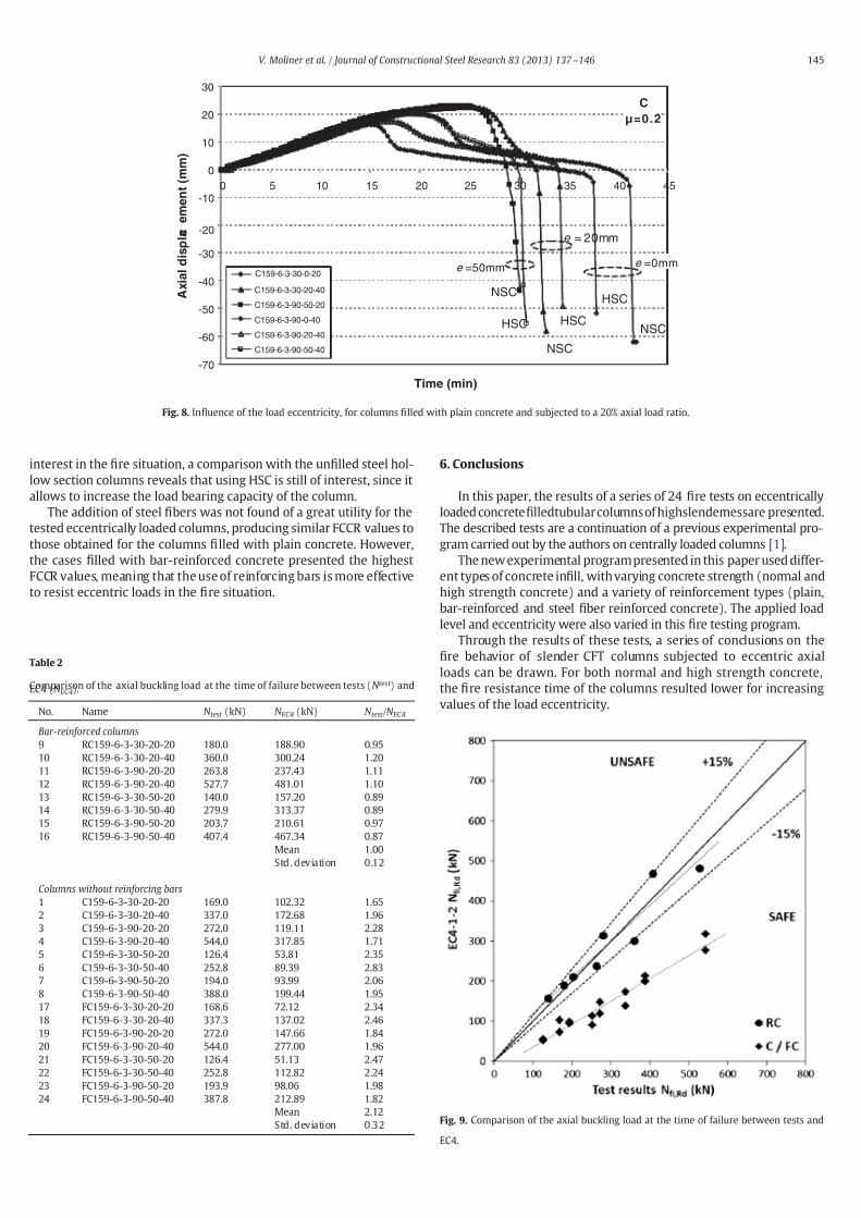
7172019 1-s20-S0143974X13000308-main
httpslidepdfcomreaderfull1-s20-s0143974x13000308-main 1010
The 1047297re resistance of the HSC specimens was found lower than
that of the NSC specimens for the higher load levels (40) while for
the smaller load levels (20) the HSC specimens produced the same
or higher 1047297re resistance times with a higher axial load applied in
terms of absolute values A comparison in terms of FCCR reveals
that using HSC is still of interest in the 1047297re situation since it allows
to increase the load bearing capacity of the columns
The use of steel 1047297bers did not show an increase in the 1047297re resis-
tance of normal or high strength concrete1047297lled columns under eccen-
tric loads since the failure in most of the tests was due to the hollow
steel column premature buckling the concrete in1047297ll only helping to
delay the heating of the column but not contributing to sustain the
load Nevertheless an improvement in the 1047297re resistance was found
when using reinforcing bars as it had been previously observed for
centrally loaded columns [1] The addition of reinforcing bars pro-
duced a signi1047297cant bene1047297t in the 1047297re resistance of the eccentrically
loaded specimens helping in some cases to avoid a premature failure
of the column
Therefore it can be concluded that for slender CFT columns no
special bene1047297t in the 1047297re resistance is found through the addition of
steel 1047297bers while the use of reinforcing bars can improve the 1047297re per-
formance of these columns under eccentric loads
The simple calculation model for composite columns from Eurocode
4 Part 12 was evaluated by means of the results of this series of 1047297re
tests In contrast with previous results obtained for centrally loaded col-umns where the method had been found unsafe for slender columns
[1] under eccentric loads the method turns to the safe side although
producing high errors for those columns which do not make use of
reinforcing bars Nevertheless for bar-reinforced columns the method
results in accurate predictions Therefore it is suggested here that the
current simple calculation model in Eurocode 4 Part 12 should be re-
vised and improved in the future on the basis of this 1047297ndings
Acknowledgments
The authors wish to express their sincere gratitude to the Spanish
Ministry of Science and Innovation for the help provided through pro-
ject BIA 2009_09411 to the Generalitat Valenciana for the IMPIVA
funds in the framework of the project FUEGOSTRUCT and to the Euro-
pean Community for the FEDER funds
References[1] Romero ML Moliner V Espinos A Ibantildeez C Hospitaler A Fire behavior of axially
loaded slender high strength concrete-1047297lled tubular columns J Constr Steel Res2011671953ndash65
[2] Twilt L Hass R Klingsch W Edwards M Dutta D Design guide for structural hol-low section columns exposed to 1047297re Cologne Germany Comiteacute Internationalpour le Deacuteveloppement et lEtude de la Construction Tubulaire (CIDECT) 1996
[3] Wang Y Kodur V Research toward use of unprotected steel structures J StructEng 2000126(12)1442ndash50
[4] Lie TT Chabot M Experimental studies on the 1047297re resistance of hollow steel col-umns 1047297lled with plain concrete Internal report No 611 Ottawa Canada Institutefor Research in Construction National Research Council of Canada (NRCC) 1992
[5] Chabot M Lie TT Experimental studies on the 1047297re resistance of hollow steel col-umns 1047297lled with bar-reinforced concrete Internal report No 628 Ottawa Cana-da Institute for Research in Construction National Research Council of Canada(NRCC) 1992
[6] Kodur VKR Latour JC Experimental studies on the 1047297re resistance of hollow steelcolumns 1047297lled with high-strength concrete Ottawa Canada Institute for Re-
search in Construction National Research Council of Canada (NRCC) 2005[7] Grandjean G Grimault JP Petit L Deacutetermination de la dureacutee au feu des pro1047297les
creus remplis de beacuteton CIDECT Research Project 15Bndash8010 Cologne GermanyComiteacute International pour le Deacuteveloppement et lEtude de la ConstructionTubulaire 1980
[8] Kordina K Klingsch W Fire resistance of composite columns of concrete 1047297lledhollow sections CIDECT Research Project 15C1C2ndash8327 Cologne GermanyComiteacute International pour le Deacuteveloppement et lEtude de la ConstructionTubulaire 1983
[9] Renaud C Kruppa J Unprotected concrete 1047297lled columns 1047297re tests mdash veri1047297cationof 15Q CIDECT Research Project 15R Saint-Reacutemy-legraves-Chevreuse France CentreTechnique Industriel de la Construction Meacutetallique (CTICM) 2004
[10] Renaud C Joyeux D Kruppa J Improvement and extension of the simple calcula-tion method for 1047297re resistance of unprotected concrete 1047297lled hollow columnsCIDECT Research Project 15Q-1203 Saint-Reacutemy-legraves-Chevreuse France CentreTechnique Industriel de la Construction Meacutetallique (CTICM) 2004
[11] Han L Zhao X YangY Feng J Experimental study and calculation of 1047297re resistanceof concrete-1047297lled hollow steel columns J Struct Eng 2003129(3)346ndash56
[12] Lu H Zhao XL Han LH Fire behaviour of high strength self-consolidating concrete
1047297lled steel tubular stub columns J Constr Steel Res 200965(10ndash11)1995ndash2010[13] Schaumann P Kodur V Bahr O Fire behaviour of hollow structural section steel
columns 1047297lled with high strength concrete J Constr Steel Res 200965(8ndash9)1794ndash802
[14] CEN EN 1994-1-2 Eurocode 4 design of composite steel and concrete structuresPart 1ndash2 general rules mdash structural 1047297re design Brussels Belgium ComiteacuteEuropeacuteen de Normalisation 2005
[15] Espinos A Romero M Hospitaler A Advanced model for predicting the 1047297re re-sponse of concrete 1047297lled tubular columns J Constr Steel Res 201066(8ndash9)1030ndash46
[16] Lacuesta C Romero ML Ivorra S Portoles JM A three-dimensional numericalmodel of circular concrete 1047297lled columns In Topping BHV Montero GMontenegro R editors Proceedings of the eight international conference oncomputational structures technology Stirlingshire UK Civil-Comp Press2006 httpdxdoiorg104203ccp8322 [Paper 22]
[17] CEN EN 1363-1 1047297re resistance tests Part 1 general requirements Brussels Bel-gium Comiteacute Europeacuteen de Normalisation 1999
[18] CEN EN 1994-1-1 Eurocode 4 design of composite steel and concrete structures
Part 1-1 general rules and rules for buildings Brussels Belgium ComiteacuteEuropeacuteen de Normalisation 2004[19] ISO 834 Fire resistance tests elements of building construction Switzerland In-
ternational Standards Organisation 1980[20] Lennon T Moore DB Wang YC Bailey CG Designers guide to EN 1991-1-2 EN
1992-1-2 EN 1993-1-2 and EN 1994-1-2 Thomas Telford Limited 2007[21] Espinos A Romero ML Hospitaler A Simple calculation model for evaluating the
1047297re resistance of unreinforced concrete 1047297lled tubular columns Eng Struct201242231ndash44
[22] Espinos A Gardner L Romero M Hospitaler A Fire behaviour of concrete 1047297lled el-liptical steel columns Thin-Walled Struct 201149(2)239ndash55
Table 3
Fire concrete contribution ratio (FCCR)
No Name FRR concrete-1047297lled
(min)
FRR hollow(min)
FCCR
1 C159-6-3-30-20-20 32 14 229
2 C159-6-3-30-20-40 16 10 160
3 C159-6-3-90-20-20 34 12 283
4 C159-6-3-90-20-40 11 6 183
5 C159-6-3-30-50-20 29 16 188
6 C159-6-3-30-50-40 23 11 2097 C159-6-3-90-50-20 30 13 231
8 C159-6-3-90-50-40 16 9 178
9 RC159-6-3-30-20-20 47 15 320
10 RC159-6-3-30-20-40 2 4 11 218
11 RC159-6-3-90-20-20 4 8 12 400
12 RC159-6-3-90-20-40 22 8 288
13 RC159-6-3-30-50-20 3 9 15 260
14 RC159-6-3-30-50-40 2 0 11 182
15 RC159-6-3-90-50-20 4 0 12 333
16 RC159-6-3-90-50-40 15 6 267
17 FC159-6-3-30-20-20 30 14 221
18 FC159-6-3-30-20-40 16 11 155
19 FC159-6-3-90-20-20 23 12 192
20 FC159-6-3-90-20-40 13 6 217
21 FC159-6-3-30-50-20 30 15 200
22 FC159-6-3-30-50-40 19 11 173
23 FC159-6-3-90-50-20 29 12 24224 FC159-6-3-90-50-40 14 8 188
Mean 230
146 V Moliner et al Journal of Constructional Steel Research 83 (2013) 137 ndash146


