Embed Size (px)
Citation preview
A
ittscuas©
K
1
jcwauvttopc
ppPf
0d
Wear 263 (2007) 727–735
Microstructural aspects of wear in soft tribological alloys
R. Schouwenaars ∗, V.H. Jacobo, A. OrtizDepartment of Mechanical Engineering, DIMEI, Universidad Nacional Autonoma de Mexico,
Avenida Universidad 3000, 04510 Coyocacan, Mexico D.F., Mexico
Received 13 August 2006; received in revised form 30 November 2006; accepted 9 December 2006Available online 23 May 2007
bstract
Soft tribological alloys, based on the Al–Sn and Cu–Pb systems, have been used for decades in journal bearings, but detailed studies on thenteraction between wear and microstructures in such materials are rare. This work analyses a series of laboratory tests and case studies to elucidatehe relationship between wear and the underlying microstructural processes in these alloys. SEM-results of sections through the tribolayer revealwo important processes. While the tribological compatibility between the materials prevents the formation of a transfer layer, auto-transfer ofeized bearing material onto the bearing surface is common under severe loading conditions. This results in mechanical mixing of the alloyomponents, producing metastable and driven phases in the tribolayer. A simple analysis based on the free energy of mixing provides qualitative
nderstanding of these effects. The second feature is formed by localised zones of severe plastic deformation showing pronounced vorticity. Thesere distinguished from other documented vortices formed during wear by the fact that their axis is parallel to the sliding direction and by the largetrain level and may be explained by cyclic plasticity, induced by hydrodynamic pressure oscillations due to asperities on the rotating shaft.2007 Elsevier B.V. All rights reserved.
ip line
AWm
hcmsro
unot1
eywords: Journal bearing; Tribolayer; Mechanical alloying; Plastic vortex; Sl
. Introduction
With more than 109 bearing shells produced annually [1],ournal bearings can hardly be considered a niche product. Theyonsist of a cylindrical steel shell with a thin overlay of whatill be called a “soft tribological alloy”, which typically hasthickness of 0.2 mm. As a consequence, a common bearing
ses only between 1 and 10 g of overlay, resulting in a low-olume product with high added value. The first designated softriboalloys (patented by Isaac Babbit in 1839 [2]) were based onhe Pb–Sb–Sn system. If used as overlays, they are directly castnto the steel strip [3]. Their low strength and low melting pointrohibit their use in fast-running engines and the toxicity of theiromponents presents environmental and occupational hazards.
Electroplated Babbit is still extensively used as a coating torotect Cu–Pb alloys from corrosion. In Cu–Pb alloys, the Cu-
hase provides strength and ductility and a reticular network ofb provides the anti-friction and anti-adhesion characteristicsound in Babbits. Cu–Pb was partially substituted by Al–Sn and∗ Corresponding author. Tel.: +52 55 56 22 80 57; fax: +52 55 56 22 80 58.E-mail address: raf [email protected] (R. Schouwenaars).
ctc[cic
043-1648/$ – see front matter © 2007 Elsevier B.V. All rights reserved.oi:10.1016/j.wear.2006.12.037
field; Thermodynamic stability
l–Pb alloys due to copper shortages during the Second Worldar. Al-based alloys now predominate in European and Asianarkets for compact engines.All important soft triboalloys have been developed in the first
alf of the 20th century, i.e. prior to the introduction of dislo-ation theory [4] and electron microscopy [5] into mainstreametallurgy. More surprisingly, little or no evolution has been
een in their processing and properties, as can be learned fromeviews on the subject over the years [7–9], as well as from somef the few technical papers available in open literature [10–14].
Such limited research and technological evolution can benderstood from the basic observation that soft triboalloys doot normally present significant wear. In a well designed engine,perated under normal conditions, bearings are generally foundo show no more than a slight surface polish, even after00,000 kms. Evidently, the alloys are not immune to wear, butomponents are designed well within infinite-life limits. Addi-ionally, hydrodynamic lubrication [1,15] prevents solid–solidontact in the bearing-crankshaft tribopair. Marginal lubrication
16,17] occurs only during engine start-up and severe regimehanges; dry friction is (almost) never present. This is importantn the design of wear experiments, as it has been shownlearly that even in dry friction the atmosphere is of primordial
7 / Wear 263 (2007) 727–735
i[
tcapdadk
totmotdsc
2
2
aiedtcfal
2
atascaiU
aedtadea
Ft
cad
ateimwi
2
etCaTiBa(fb
wwaadwfE
28 R. Schouwenaars et al.
mportance for the friction and wear of Al-based triboalloys18].
Increasing demands for engine efficiency have now reachedhe point where the load bearing capacity of existing alloys isonsidered a limit for design. The use of lighter cylinder blocksnd a higher peak pressure (needed to increase the specific out-ut) increase the load on the bearing surface as well as the timeuring which marginal lubrication occurs [19]. Smaller bearingslso help reducing mechanical losses, but new alloys cannot beesigned and existing ones cannot be optimised without precisenowledge of damage mechanisms.
This work will focus on the wear mechanisms in existingriboalloys when exposed to severe conditions. Little would bebserved under normal loading conditions (under which no morehan run-in is observed) and future alloys will be exposed to
ore demanding regimes of operation. Some information wasbtained from failure cases, which were used as a reference forhe experiments. Focus will be on the microstrucutral changesuring wear, because relatively little was learned from the wornurfaces, due to the presence of sufficient lubrication in mostases.
. Experiments
.1. Failure cases
All failure cases reported to a bearing manufacturer overperiod of 10 years were investigated by the authors. These
nclude cases remitted by large engine builders as well as smallerngine rebuilders. The overwhelming majority of cases wereue to gross errors during engine assembly, generally relatedo insufficient cleaning after machining and shot-peening. Onease, due to corrosion, has been reported elsewhere [20]. Only aew examples related to shaft misalignment or machining toler-nces were found to cause the kind of damage related to severeoading conditions and will be discussed into more detail.
.2. Wear tests
At the moment of writing, there seems to be no generallyccepted test method to evaluate the wear and fatigue resis-ance of journal bearings. A widely used family of wear testspplies a load by means of a hydraulic cylinder acting on atationary bearing with rotating shaft operating under fully lubri-ated conditions. Another family, known as the Underwood test,pplies a varying load by means of eccentric weights on a rotat-ng shaft, which is supported by connecting rods [6,10,11]. Thenderwood test is often referred to as a fatigue test.In both types of rigs, only approximate knowledge exists
bout pressure and temperature in the lubricating film. This isxplained by the fact that that a shaft running on a set of hydro-ynamically lubricated bearings (some or all of whom are theest samples) is a hyperstatic system; moreover, the bearings
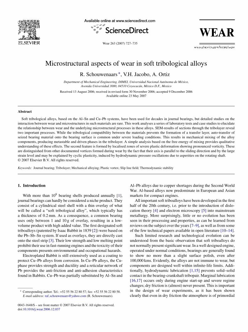
re complex non-linear components. A full description of theynamic behaviour of the test rig needs to take into accountlastic deformation and thermal expansion of the componentsnd the proper solution of the Reynolds equation under dynamicTmsi
ig. 1. Image showing the basic scheme of the Underwood testing rig (omittingransmission and lubrication systems).
onditions [1,2,15]. Reports on a fully dynamic calculation ofcrankshaft with lubricated bearings have reached the public
omain only recently [21].Consequently, results of such a test have a qualitative char-
cter and permit ranking different materials whenever they areested on the same rig under comparable conditions. On differ-nt rigs with similar designs, the physical phenomena involvedn wear are expected to be similar, even if quantitative results
ay differ. Taking these considerations into account, an Under-ood testing rig was designed based on information available
n literature [6,10,11] (Fig. 1.).
.3. Materials and materials characterisation
Five sets of new connecting rod bearings for four-cylinderngines were purchased. All examples in the study refer towo important commercial alloys. The first one (SAE 49P) isu–24%Pb–1%Sn (weight percent), produced by sintering pre-lloyed powder onto steel strip in a continuous annealing line.he bimetal strip, with a typical thickness of 200 �m after shap-
ng and machining, is electroplated with a 20 �m SAE 191abbit coating (Pb–10%Sn), resulting in a trimetal, function-lly graded system. The Al-based samples use alloy SAE 783Al–20%Sn–1%Cu), which is produced by thin slab casting,ollowed by cold rolling, annealing and cladding onto the steelacking [14].
Two bearings of each producer were tested in the Under-ood rig; another one was destined to metallography. Testsere run for 30 h at 1700 rpm (≈2.5 × 10⁶ cycles). Temper-
ture was monitored at the bearing surface and was constantt 140 ± 10 ◦C. Sections of worn parts were prepared by stan-ard metallographic practice. The SAE 49P samples were etchedith a mix of 1/3 concentrated ammonia, 1/3H2O2 and 1/3H2O
or 10 s. Observations were done on a Philips XL20 Scanninglectron Microscope.
The natural reference system for bearings is given in Fig. 2.
he sliding direction (SD) corresponds to the direction of move-ent between shaft and bearing. In this study, all metallographicections are cut perpendicular to the sliding direction. Thenformation contained in transverse sections is omitted by this

R. Schouwenaars et al. / Wear 263 (2007) 727–735 729
F(t
aotimp
3
3
bwatoabimbhpot
FRp
FA
mbwpnWtdw
FisrPifl
ig. 2. Sample reference system for strip and bearings, indicating the NormalND), Transverse (TD) and Sliding Direction (SD) of the Bearing shell. TD ishe rolling direction (RD) of the strip during manufacturing.
pproach. Other studies on the microstructural modificationf ductile metals during wear have focused instead on sec-ions perpendicular to TD, omitting the information containedn the ND–SD-plane [22–25]. Neither approach is complete;ore detailed metallographic characterisation will have to be
erformed in future experiments.
. Results
.1. Some observations from failure analysis
Some of the essential features of journal bearing failure wille outlined by means of a series of micrographs. Fig. 2 illustrateshat happens if insufficient cleaning is applied after machining
nd shot-peening of the crankshaft. Chips and shot are retained inhe lubrication channels and failure occurs quickly during testingf the engine. This is an evident example of severe errors duringssembly and is not related to the fundamentals of bearing wear,ut the example explains the concept of “embeddability”, whichs the capability to trap hard particles, preventing damage to the
ore expensive parts of the engine. It is seen in Fig. 3 (trimetalearing) and in Fig. 4 (Al–Sn alloy) that such severe damage
ardly causes any material loss, because the alloys respond bylastic deformation, as evidenced in Fig. 4 by the deformationf the Sn-phase and by the embedded wear flakes at the base ofhe scratch.ig. 3. Particle of shot ploughing through the surface of a Cu–Pb-triboalloy.ather than suffering material loss due to chip removal, the alloy deformslastically.
i
Tah
Fo
ig. 4. Section through a groove generated by a chip of nodular cast iron in anl–Sn alloy. The Sn-phase (white) serves as a marker for the strain field.
The next series of examples corresponds to a V6-engine withisalignment of the crankshaft, resulting in severe wear of the
earings in the first cylinder, gradually decreasing to almost noear at the sixth. This permits to investigate a single set ofroducts at varying degrees of wear. In Fig. 5, the coating isot yet worn away, but is clearly affected by the wear process.ear debris of the Cu–Pb-alloy (generated in other zones of
he system) is embedded in the babbit. The debris is not justeposited on top of the coating; but is mixed with it throughear-induced mechanical alloying.A more advanced stage of this alloying process is seen in
ig. 6. Here, all the flakes are broken into fine particles, mixedntimately within a Babbit matrix. The particles have an ellip-oidal form, which can be understood from the thermodynamicequirement for reducing the surface energy between the Cu andb-phases. Diffusion can be supposed to be strongly enhanced
n these structures due to the high specific area of the originalakes and the high defect content (dislocations and vacancies)
nduced by severe plastic deformation.
Fig. 7 shows the surface in the most severely affected zone.he coating has worn away and a damage pattern typical fordhesive wear is found, indicating that the pressure was tooigh for a significant oil film to be formed. Still, the interest-
ig. 5. Tribolayer formed by mechanical mixing of Cu–Pb flakes removed atther zones of the system and embedded into the original babbit coating [26].

730 R. Schouwenaars et al. / Wear 263 (2007) 727–735
Fig. 6. Tribolayer formed by mechanical mixing of Cu-based wear debris withths
isflpatstTa
f(twcprnat
FS
Fig. 8. Section through the most severely worn part of Fig. 7. The sliding direc-tion is perpendicular to the plane of the image (not to the right). Importantfww
ou
3
tsatbiSwtc
he Babbit coating. The cyclic mechanical action imposed by the rotating shaftas refined and broken up the original Cu-flakes while diffusion has lead to theirpheroidisation [26].
ng part of the information is contained in the metallographicections. Fig. 8 illustrates how a tribolayer develops. Small Cuakes are embedded in the Pb phase, and a rim of finely dis-ersed Pb is found around the lead particles, as indicated byclearer grey tone in the backscattered electron image. The
ribolayer is not limited to the immediate surface, as can beeen from the presence of Cu heterogeneously dispersed inhe Pb-phase (darker grey zones within a white Pb-particle).he mechanically mixed zone extends at least 12 �m into thelloy.
The observation of grey levels intermediate to the dark levelor Cu and the white level of Pb in the Backscattered electronBSE) images indicates the formation of mixtures whose struc-ure cannot be resolved using BSE in the SEM. Some hints abouthether these are metastable solid solutions or very fine parti-
le distributions can be obtained from Fig. 9. Submicron Pbarticles are arranged along a regular pattern in a Cu-grain, sur-
ounded by clouds of more homogeneous Pb-rich material (butot by pure Pb). The authors consider this as an indication thatn unstable phase was formed during mechanical mixing whichhen decomposes spinodally during extended testing or storageig. 7. Surface of a severely overloaded bearing, showing adhesive wear of theAE49P-surface which was exposed after removal of the coating.
lsst
Fb
eatures are: (A) fresh Cu flakes embedded in the Pb-phase; (B) Pb-rich rimithin the Cu-phase as evidenced by atomic number contrast; (C) Cu-rich zonesithin the Pb-phase well below the exposed surface of the bearing [26].
f the prepared samples. Such room temperature ageing is notncommon for low-melting alloys [3,27].
.2. Results of wear tests
In the Underwood rig, testing conditions are probably gen-ler than in the last example, but the duration of the test isignificantly longer. Tribolayers are generally more extendednd better developed. The most striking feature in all samples ishe vortex character of plastic flow which is clearly illustratedy the morphology of the second phase and etching patternsn the copper grains (Fig. 10). The axis of vorticity is alongD, contrary to other studies where a less developed vorticityas observed with axis along TD [23,24]. By assuming that the
hickness reduction of the second phase particles after tribologi-al modification is a measure for strain, true (logarithmic) strains
arger than 4 are estimated in the Cu–Pb alloy; for the Sn-alloy,trains are larger than 6. In the latter, the particles break up inmall fragments which become unrecognisable at the nucleus ofhe vortex.ig. 9. Unmixing driven by thermodynamic instability of a Cu–Pb phase formedy mechanical mixing [26].

R. Schouwenaars et al. / Wea
Fig. 10. Section through a Cu–Pb alloy. A fully developed vortex with tribolog-ically modified nucleus is shown (A). Etching patterns around the nucleus arean indication of the plastic flow, a rotation of at least 180◦ can be derived fromthe flow patterns (B). Grain refinement in Cu is seen at the surface (C).
Fig. 11. Details of a severely mixed vortex nucleus. Large zones of intermediategsb
tbbtbcsvga
4
4
rro
boarT5aoiafcgssp
st[swcbibmitnth
4
utctolbdgtbhFatai
rey levels indicate the mixture of Cu and Pb while ellipsoidal grains of Cu areurrounded by a thin rim enriched in Pb. Some pores are present, possibly createdy the annihilation of excess vacancies.
In the Al–Sn alloy, Sn-grains break up into small particlesoward the centre of the vortex. Enhanced solubility is suggestedy the cloudy appearance of the nucleus, but this may as welle an electron-optic effect. In the Cu–Pb alloy, it is seen thathe extruded Pb-ribbons disappear into the nucleus of the vortexefore breaking up mechanically. The structure of the nucleusannot be determined in Fig. 10. Fig. 11 (BSE, unetched sample)hows the detail of a heavily intermixed zone in the nucleus of aortex, where Pb-rich rims can be found around ellipsoidal Curains, apparently created by the unmixing of Cu and Pb fromn unstable phase.
. Discussion
.1. Testing method
To guarantee that engine components are tested under fullyealistic conditions, the dynamometer is used: a real engine isun under controlled conditions, preferably with a high degreef instrumentation. It would not be too difficult to modify the
wi
l
r 263 (2007) 727–735 731
earing-shaft assembly such as to introduce controlled levels ofverload onto the bearing surface. However, such proceduresre expensive and are generally substituted by simplified testigs which are still relatively large and difficult to instrument.his was not deemed critical when the methods were designed0 years ago. The Underwood rig was originally conceived asfatigue test. In modern bearing shells, the triboalloy forms
nly a thin overlay. The critical crack length to induce fatiguen these highly ductile materials is likely to be larger than thelloy thickness, while the steel backing shields the triboalloyrom elevated stresses and the bearing operates under elevatedompressive stresses. Hacifazlioglu and Karadeniz [28] investi-ated the presence of tensile stresses and found that small tensiletresses are present at the leading edge of the hydrodynamic pres-ure distribution. They did not take into account the compressivere-stresses applied during assembly.
The present authors attempted to detect the presence of exces-ive tensile or shear stresses due to the complex features of thewo-phase microstructure by means of finite element models29]. It was found that tensile stresses never occur and thathear stresses reach critical values only at nominal pressureshich were twice the ones expected in normal engine appli-
ations. Apparently, fatigue is not a real concern in modernearing shells. Even if the Underwood test is not a fatigue test,t does produce interesting results. Although it is not possi-le to assign precise values of pressure or frictional forces, theicrostructures can be studied in the framework of the phys-
cal and mechanical metallurgy of tribolayer formation. Fromhe viewpoint of modern tribometry, the Underwood test doeso longer fit the standards. Precise tribometers which respecthe geometry and lubrication conditions of the axis-bearing pairave to be developed.
.2. On the mechanical aspects of tribolayer formation
The study of tribolayer formation is fundamental for thenderstanding of wear in ductile materials [22–25,30–33]. Fromhe viewpoint of substructural refinement [22,33], this processlearly falls under the classification of severe plastic deforma-ion (SPD) [34,35]. It is characterised by the rapid accumulationf dislocations during the early stages of straining, whichower their energy by accommodating into low-angle subgrainoundaries. Upon further deformation, the subgrain diameterecreases, while subrgrain misorientation increases and sub-rain boundary thickness is reduced. At a certain level of strain,he accumulated misorientation is such that high-angle grainoundaries appear, marking the continuous transition between aeavily deformed material and a nanostructured (SPD) material.or FCC metals, this transition occurs around equivalent (log-rithmic) strains of 4–6, which are doubtlessly reached in theribolayers. A recent orientation mapping study by Battaile etl. illustrated this phenomenon in Ni-single crystals, document-ng how a refined polycrystal structure developed during sliding
ear [25]. It is logical to assume that the same process is activen Cu–Pb (Fig. 10) and Al–Sn alloys.There is a clear distinction between SPD processing and tribo-
ayer formation. In the first, a small number of passes with high

7 / Wear 263 (2007) 727–735
ssdhshppcmi
dttapsdfluacs
fliafsse{
o{
wcpto(tafssot
o
Fib
iibtntscioF
trirpure plane strain. Rotational fields such as shown in Fig. 10 andthe left-hand side of Fig. 14 can be understood either from theviewpoint of Fig. 12 or Fig. 13. Fig. 12 would present the caseof a localised pressure peak caused by the presence of an asper-
32 R. Schouwenaars et al.
train is applied. During wear, only small zones of the materialurpass their yield strength momentarily, causing small localeformations which may stop and jump to other regions if strainardening is sufficient. Even so, only 10,000 cycles of 0.1%train would be necessary to reach a SPD of 10. SPD processesave been designed specifically to maintain a high hydrostaticressure to prevent void formation and fracture, while wearrocesses have not. Nonetheless, high hydrostatic pressures areharacteristic for the contact zone and thus may permit the accu-ulation of large strains before fracture occurs and wear debris
s generated.What appears to distinguish the present materials from other
uctile materials is the formation of pronounced sideward vor-ices. The word “Sideward” is introduced to distinguish fromhe well-documented “Forward” vortices which have their axislong TD and are found in dry sliding wear of less-ductile, singlehase alloys [23,24]. Forward vortices are explained by the sheartrain induced by friction at the sliding interface, producing aisplacement gradient analogous to the one found in Poisseuilleow. Whether such phenomenon occurs in the present case isncertain due to the choice of reference system. An argumentgainst it is the fact that tests were performed under lubricatedonditions, which reduce the tangential loads compared to dryliding.
In an attempt to formulate a phenomenological explanationor the observed flow fields, the analogy with two classical slipine field (SLF) solutions for ideal plane strain plasticity wasnvestigated. The SLF is the graphical presentation of the char-cteristics of the parabolic equation that describes plastic flowor an incompressible, rigid-plastic medium subject to planetrain [36]. The lines correspond to the direction of maximumhear strain. The SLF can be dually described by the Henckyquations:
dp + 2k dφ = 0 (α-line)
dp − 2k dφ = 0 (β-line)(1)
r the Geiringer equations
du − v dφ = 0 (α-line)
dv + u dφ = 0 (β-line)(2)
here the former express stress equilibrium and the latter strainompatibility. p is the hydrostatic pressure, k the yield strength inure shear and the angle φ = α + β is the rotation angle betweenhe characteristic curvilinear co-ordinate system and the co-rdinate system at each point (x, y) of the physical plane, α
respectively, β) is the variation of φ along an α-line (respec-ively, β-line). u and v are the velocity components along the α
nd β lines, respectively. Two classical solutions are of interestor the present study (for a comprehensive textbook treatment,ee Chakrabarty [37]). The first one is the classical Prandtl-olution for indentation by a flat punch (Fig. 12), the second
ne corresponds to the compression (expansion) of a cylindricalube (Fig. 13).It is relatively easy to connect the outward movement of theuter triangles in the Prandtl field to the flat ridges observed
Fsf
ig. 12. Prandtl SLF for indentation by a flat punch. The central triangular zones pushed down, the outer triangles move up and out at an angle of 45◦ as rigidodies.
n Fig. 3. However, this geometry is affected by the restraintmposed by the rotating shaft. The Prandtl field predicts rigidody translation in the triangular regions and rigid body rota-ion in the fans. Fig. 4 clearly shows a strain gradient in theeighbourhood of the indentation. Indentation problems haveherefore been studied rather through the analogy with the expan-ion of a spherical cavity [41]. A plane strain equivalent is theompression of a cylindrical cavity (Fig. 13). Instead of a cav-ty, one can imagine the presence of a soft zone (e.g. Pb or Snccupying the triple line between adjoining matrix grains). Inig. 13, Strain increases inversely proportional with r2.
Many theoretical objections can surely be formulated againsthis proposal. There is no cavity in the physical problem and aigid-plastic boundary which complies with all the mathemat-cal conditions of SLF-theory cannot be found. However, theeal material is not ideally rigid-plastic and the problem is not
ig. 13. SLF for the compression of a cylindrical cavity under an external pres-ure p. The slip lines are logarithmic spirals, α and β can be interchangedreely.

R. Schouwenaars et al. / Wea
Fig. 14. Tribological modification of a SAE783 alloy. To the left, a divergingpattern of extruded Sn-particles indicates an outward material flow (A). To therwc
ieswnItt
4
mnpagitSs
ootsnto
r(
�
Ctse
�
Ta
c
i⎡⎢⎣
a
ight, a similar flow is seen, but instead of diverging, it converges to form aell-developed vortex (B). A smaller vortex is found at the centre (C) and more
omplex patterns are seen in the upper right part of the micrograph (D).
ty on the rotating shaft, while Fig. 13 would correspond to theffect of a more extended zone of high pressure which samples aoft spot beneath the surface. Small displacements at the surfaceould result in large displacements at the centre and the vortexucleus seen in Fig. 15 would have to be interpreted as a “sink”.n the real problem, material is lost at the surface, not in the cen-re of the vortices. Three-dimensional flow patterns are neededo explain the observed phenomena in a rigorous manner.
.3. On the thermodynamics of tribolayer formation
The reasons why non-equilibrium phases are formed duringechanical mixing of alloys are still far from clear. Surya-
arayana, in an extensive review [39] as well as Ma [40,41] avoidresenting quantitative assessments of this problem. The latterlso indicates the difficulty of demonstrating that a real homo-eneous phase is formed, even with highly advanced analytic
nstruments and specimens prepared under controlled labora-ory conditions. A definite answer must not be expected from aEM-analysis on worn journal bearings. A simple approach fortudying phase instability is found by considering the nucleationFig. 15. Centre of the vortex.
a
T
�
Ig
V
S
Euae
r 263 (2007) 727–735 733
f a second phase in a supersaturated solid solution. The goalf such model is not to reach quantitative agreement, but rathero explore the nature of the phenomena involved. Consequently,train energy will be neglected and only approximate thermody-amic parameters will be used. A more complete analysis, basedhermodynamic databases, can be made but is outside the scopef this paper.
If a particle of Pb or Sn were to precipitate from a supersatu-ated solid solution in Cu or Al, the driving force for precipitation�Gp) would be given by [38]:
Gp = RT ln
(C0
CM
)(3)
0 represents the molar concentration of the supersaturated solu-ion and CM the equilibrium concentration in the matrix. A smallpherical particle embedded in the matrix would have a freenergy of:
G = −4πr3
3
�Gp
Vm+ 4πr2γ (4)
he second term accounts for the surface energy γ of the particlend Vm is its molar volume. The critical radius rc is given by:
∂�G
∂r= 0 or rc = Vm
2γ
�Gp(5)
Smaller particles will shrink and disappear; larger particlesan lower their free energy by growing.
Now if a spherical particle with radius r0 is deformed accord-ng to a (logarithmic) strain tensor:
ε11 0 0
0 ε22 0
0 0 −(ε11 + ε22)
⎤⎥⎦ (6)
Then, the particle transforms into an ellipsoid whose principalxes are equal to:
= r0eε11 ; b = r0eε22 ; c = r0e−ε11−ε22 (7)
he free energy of the particle is now:
G = −VE�Gp
Vm+ SEγ (8)
n (8), VE is the volume and SE the surface area of the ellipsoid,iven by:
E = 4π
3abc (9)
E =∫ π
02√
2b√
a2 + c2 + (a2 − c2)cos 2φE
×[
2(b2 − a2)c2 sin2 φ
b2(a2 + c2 + (a2 − c2)cos 2φ)
]sin φ dφ (10)
(ϕ) is the Elliptic Integral of the Second Kind; (10) was eval-ated numerically. The stability criterion is no longer as simples (5), because particles can lower their free energy by changingither size (r0) or shape.

734 R. Schouwenaars et al. / Wear 263 (2007) 727–735
Table 1Estimation of thermodynamic data for the assessment of particle evolution in deformed Cu–Pb and Al–Sn alloys
θMP (◦) γMM (J/m2) γ (J/m2) Vm (10−6 m3) C0 (at%) CM (at%) �Gp (kJ/Mol) rc (nm)
CA
l6afcf
γ
γ
oqsi0Paaa
gwicp
Fpb
obirdwbahiind
Eoeisom
u–Pb 46 0.38 0.27 18.2l–Sn 33 0.6 0.36 16.3
Surface energies for Cu–Pb or Al–Sn are not readily found initerature. As an indication, cusp angles 2θ of 92◦ for Cu–Pb and6◦ for Al–Sn were measured at the intersection of phase bound-ries with grain boundaries in the matrix. These intersections areormed under conditions of liquid–solid equilibrium but may beonsidered approximations for the incoherent solid–solid inter-ace. The matrix–particle surface tension γMP is calculated by:
MM = 2γMP cos θ (11)
MM was taken from Ref. [42]. The equilibrium solubilityf the alloying elements into the matrix is another difficultuestion. Although both systems are generally considered tohow “zero” solid solubility, thermodynamically spoken, thiss not true. Scant literature data on the present systems give.01 at% of Sn in Al at room temperature [43] and 0.05 at% ofb in Cu at 873 K [44]. Because such small levels of solubilityre difficult to determine even through detailed thermodynamicnalysis, a value of Cm = 0.02% will be assumed for both alloyst a testing temperature of 413 K.
The relevant parameters are resumed in Table 1.The result of the analysis is given by Fig. 16, which plots the
radient of −�G (8). This gradient indicates how the particles
ould evolve if left to thermodynamic effects only. Also plotteds the line at which ∂�G/∂r = 0. To the left of this line, a parti-le would diminish its volume by dissolution, to the right, thearticle would grow.
ig. 16. Gradient of −�G, indicating the sense of evolution of an ellipsoidarticle in the absence of additional strain increments induced by wear. Thelack line indicates the condition ∂�G/∂r = 0.
bftftpl
5
ftptwjsibc
hpswma
8.8 0.02 20.9 0.465.4 0.02 19.2 0.61
Fig. 16 indicates that ductile particles which are several ordersf magnitude larger than the critical size for a nucleus wouldecome unstable if sufficiently strained. The sense of the arrowsndicates that at very high strains, particles would stabilise byeducing their ellipticity first and then would grow or shrinkepending on their original size. At lower strains, the effect iseak and simple growth or shrinking would predominate. It muste mentioned that for the present examples, the driving forcegainst dissolution is enormous (several times higher than theeat of melting of the pure metals). In the presence of metastablentermediate phases, or if the free energy of the amorphous phases lower than that of the solid solution, then the size of the criticalucleus would increase and the black line in Fig. 16 would moveownward.
There are also mechanical factors to be taken into account.xcess vacancies and dislocations will have a strong effectn the kinetics by increasing the diffusion coefficient. Theirnergetic impact is likely to be small compared to the driv-ng forces for phase transformation. A more direct effect oftrain is the mechanical break-up of elongated ribbons/flakesf second phase. This may occur when shear bands cross theicrostructure but also by tensile fracture of the ribbons. Such
reak-up can occur at much lower strains than the ones neededor thermodynamic instability and would move the particles tohe lower-left corner of Fig. 16. This is likely to be responsibleor the stringers of fine Sn-grains found in Fig. 15. Addi-ional straining would be necessary to further reduce the smallerarticles and push them over their thermodynamic stabilityimits.
. Summary and conclusions
The simplicity of tools which have hitherto been reportedor the study of wear in journal bearings stands in stark con-rast with the complexity of the problem as illustrated by thisaper. Measurement rigs which are capable of determining fric-ion and wear in a controlled manner will have to be designed,ithout deviating too much from the operation conditions for
ournal bearings. Next, instead of simply observing the wornurfaces, microstructures must be studied. Tribolayer formations a three-dimensional problem, so perpendicular sections muste combined or serial sectioning must be used to construct aomplete picture.
In spite of the relative simplicity of the observations presentedere, the complex interplay of mechanic and thermodynamicrocesses involved in tribolayer formation is clearly demon-
trated. No intermixing between shaft material and triboalloyas found. The shaft induces accumulated cyclic plastic defor-ation into the two-phase materials. The vortex patterns shownre the most striking features of the strain field.

/ Wea
Llgamfas
iemiwao
R
[
[
[
[
[
[
[
[
[
[
[
[
[
[
[
[
[
[
[
[
[
[
[
[
[
[
[
[[[
[
[
[
R. Schouwenaars et al.
An attempt was made to explain these vortices through Slipine Theory, which doubtlessly is an oversimplification. Simi-
arly, to gain some understanding on the thermodynamic effectsenerated by such high strains, a simple analogy to the nucle-tion and growth model for phase transformation was used. Thisodel indicates that thermodynamic instability plays a role to
orm the non-equilibrium structures observed, but it must bessisted by the mechanical break-up of the particles to reach aufficiently small size for dissolution.
Both models presented here can obviously be refined, mod-fied or rejected, in which case alternative hypothesis must bexplored. Rather than explaining the problem into detail, theodels indicate the fields of study which must be accessed
n this largely unexplored area. While such fields are fairlyell-defined for most other technologically important alloys,discussion to this respect seems to be non-existent in the casef soft triboalloys.
eferences
[1] J.A. Williams, Engineering Tribology, Oxford University Press, 1994.[2] M.M. Khonsari, R.E. Booser, Applied Tribology (Bearing Design and
Lubrication), J. Wiley & Sons, 2001.[3] R. Schouwenaars, J.L. Romero, V.H. Armendariz, A. Ortiz, Microstruc-
tures of rapidly solidified Sb–Sn–Pb-alloys, Adv. Mater. Res. 15–17 (2007)621–626.
[4] D.E. Newbury, D.B. Williams, The electron microscope: the materialscharacterization tool of the millenium, Acta Mater. 48 (2000) 323–346.
[5] R.E. Mehl, R.W. Cahn, Historical development, in: R.W. Cahn, P. Haasen(Eds.), Physical Metallurgy, Elsevier Science Publishers, 1983.
[6] G.C. Pratt, Materials for plain bearings, Int. Metall. Rev. 18 (1973) 62–88.[7] G.R. Kingsbury, Friction and wear of sliding bearing materials ASM
Handbook (Friction, Lubrication and Wear Technology), vol. 18, ASMInternational, 1992.
[8] K. Holmes, Solid materials, in: C.M. Taylor (Ed.), Engine Tribology, Else-vier Science Publishers, 1993.
[9] G.R. Kingsbury, Oil film bearing materials, in: Tribology Data Handbook,CRC Press, 1997.
10] G.C. Pratt, C.A. Perkins, Aluminum based crankshaft bearings for the highspeed diesel engine, SAE (1981) 810199.
11] R. Alexander, U. Engel, U. Lehmann, P. Neuhaus, AlSn10Ni2MnCu-A newhigh strength Al-bearing material, SAE (1995) 950951.
12] T. Stuczynsky, Metallurgical problems associated with the production ofaluminium–tin alloys, Mater. Des. 18 (1997) 369–372.
13] R. Schouwenaars, S. Cerrud, A. Ortiz, Analysis of the frequency, causesand consequences of a common quality problem in the babbit coating oftrimetal journal bearings, SAE 110 (2001) 1148–1154.
14] R. Schouwenaars, V.H. Jacobo, S.M. Cerrud, A. Ortiz, The obtention ofhomogeneous microstructures in Al–Sn-based tribological alloys, Mater.Sci. Forum 426–432 (2003) 387–392.
15] C.M. Taylor, Engine bearings: background and lubrication analysis, in:
C.M. Taylor (Ed.), Engine Tribology, Elsevier, 1993.16] H.S. Cheng, Lubrication regimes ASM Handbook (Friction, Lubricationand Wear Technology), vol. 18, ASM International, 1992.
17] C.M. Taylor, Lubrication regimes and the internal combustion engine, in:C.M. Taylor (Ed.), Engine Tribology, Elsevier, 1993.
[
[
r 263 (2007) 727–735 735
18] K. Lepper, M. James, J. Chashechkina, D.A. Rigney, Sliding behavior ofselected aluminum alloys, Wear 203/204 (1997) 46–56.
19] M. Priest, C.M. Taylor, Automobile engine tribology—approaching thesurface, Wear 241 (2000) 193–203.
20] R. Schouwenaars, A. Ortiz Prado, Accelerated wear in journal bearings forinternal combustion engines converted to the use of LPG, Mater. Perform.41 (12) (2002) 32–37.
21] Z.P. Mourelatos, A crankshaft system model for structural dynamic analysisof internal combustion engines, Comput. Struct. 79 (2001) 2009–2027.
22] D.A. Rigney, Transfer, mixing and associated chemical and mechanicalprocesses during the sliding of ductile materials, Wear 245 (2000) 209.
23] Y.P. Sharkeev, E.V. Legostaeva, S.V. Panin, B.P. Gritsenko, Experimentalinvestigation of friction and wear of Mo ion implanted ferritic-pearliticsteel, Surf. Coat. Technol. 158/159 (2002) 674–679.
24] V. Panin, A. Kolubaev, S. Tarasov, V. Popov, Subsurface layer formationduring sliding friction, Wear 249 (2002) 860–867.
25] C.C. Battaile, S.V. Prasad, P.G. Michael, P.G. Kotula, B.S. Majum-dar, Modelling subsurface plastic deformation, mechanical mixing andmicrostructure formation during wear on nickel single crystals. Unpub-lished research, presented at Thermec’2006, Vancouver (2006).
26] R. Schouwenaars, V.H. Jacobo, S.M. Cerrud, A. Ortiz, Tribolayer formationas a functionally self-grading process in soft anti-friction alloys, Mater. Sci.Forum 492–493 (2005) 531–536.
27] M. Abtew, G. Selvaduray, Lead-free solders in microelectronics, Mater.Sci. Eng. R 27 (5/6) (2000) 95–141.
28] S. Hacifazlioglu, S. Karadeniz, A parametric study of stress sources injournal bearings, Int. J. Mech. Sci. 38 (8/9) (1996) 1001–1015.
29] R. Schouwenaars, V.H. Jacobo, S.M. Cerrud, A. Ortiz, Finite element sim-ulation of microstresses in a traditional FGM: the case of soft tribo-alloys,Mater. Sci. Forum 492/493 (2005) 421–426.
30] A. Kapoor, F.J. Franklin, Tribological layers and the wear of ductile mate-rials, Wear 245 (2000) 204–215.
31] A. Kapoor, F.J. Franklin, S.K. Wong, M. Ishida, Surface roughness andplastic flow in rail wheel contact, Wear 253 (2002) 257–264.
32] M. Ueda, K. Uchino, T. Senumura, Effects of carbon content on wearproperty in pearlitic steel., Mater. Sci. Forum 426–432 (2003) 1175–1180.
33] D.A. Rigney, M.G.S. Naylor, R. Divakar, L.K. Ives, Dislocation struc-tures caused by sliding and by particle impact, Mater. Sci. Eng. 81 (1986)409–425.
34] N. Hanssen, New discoveries in deformed materials, Metall. Mater. Trans.A 23A (2001) 2917–2935.
35] R.Z. Valiev, R.K. Islamgaliev, I.V. Alexandrov, Bulk nanostructured mate-rials from severe plastic deformation, Prog. Mater. Sci. 45 (2000) 103–189.
36] R. Hill, The Mathematical Theory of Plasticity, Oxford University Press,Oxford, 1950.
37] J. Charkabarty, Theory of Plasticity, Butterworth-Heinemann, 2006.38] D. Tabor, The Hardness of Metals, Clarendon Press, Oxford, 2000.39] C. Suryanarayana, Mechanical alloying and milling, Prog. Mater. Sci 46
(2001) 1–184.40] E. Ma, Alloys created between immiscible elements, Prog. Mater. Sci 50
(2005) 413–509.41] E. Ma, Amorphisation in mechanically driven material systems, Scripta
Mater. 49 (2003) 941–946.42] J.W. Martin, R.D. Doherty, B. Cantor, Stability of Microstructures in Metal-
lic Systems, Cambridge University Press, Cambridge, 1997.
43] J.M. Silcock, H.M. Flower, Comments on a comparison of early and recentwork on the effect of trace additions of Cd. In of Sn on nucleation andgrowth of θ′ in Al–Cu-alloys, Scripta Mater. 46 (2002) 289–294.
44] F.H. Hayes, H.L. Lukas, G. Effenberg, G. Petzow, Z. Metallkd. 77 (1986)749.


