Embed Size (px)
Citation preview
REPORT DOCUMENTATION PAGE Form Approved
OMB No. 0704-0188 Public reporting burden for this collection of information is estimated to average 1 hour per response, including the time for reviewing instructions, searching existing data sources, gathering and maintaining the data needed, and completing and reviewing this collection of information. Send comments regarding this burden estimate or any other aspect of this collection of information, including suggestions for reducing this burden to Department of Defense, Washington Headquarters Services, Directorate for Information Operations and Reports (0704-0188), 1215 Jefferson Davis Highway, Suite 1204, Arlington, VA 22202-4302. Respondents should be aware that notwithstanding any other provision of law, no person shall be subject to any penalty for failing to comply with a collection of information if it does not display a currently valid OMB control number. PLEASE DO NOT RETURN YOUR FORM TO THE ABOVE ADDRESS.
1. REPORT DATE (DD-MM-YYYY) 31-03-2011
2. REPORT TYPEBook Chapter
3. DATES COVERED (From - To)
4. TITLE AND SUBTITLE
5a. CONTRACT NUMBER
Chapter 18 - Propulsion Systems 5b. GRANT NUMBER
5c. PROGRAM ELEMENT NUMBER
6. AUTHOR(S) Ivett A. Leyva, Marcus Young, William A. Hargus Jr., Richard Van Allen, Charles M.
5d. PROJECT NUMBER
Zakrzwski
5f. WORK UNIT NUMBER
23070725 7. PERFORMING ORGANIZATION NAME(S) AND ADDRESS(ES)
8. PERFORMING ORGANIZATION REPORT NUMBER
Air Force Research Laboratory (AFMC) AFRL/RZSA 10 E. Saturn Blvd. Edwards AFB CA 93524-7680
AFRL-RZ-ED-BK-2011-057
9. SPONSORING / MONITORING AGENCY NAME(S) AND ADDRESS(ES) 10. SPONSOR/MONITOR’S ACRONYM(S)
Air Force Research Laboratory (AFMC) AFRL/RZS 11. SPONSOR/MONITOR’S
5 Pollux Drive NUMBER(S) Edwards AFB CA 93524-7048 AFRL-RZ-ED-BK-2011-057
12. DISTRIBUTION / AVAILABILITY STATEMENT Approved for public release; distribution unlimited (PA #10985).
13. SUPPLEMENTARY NOTES For publication in textbook: “Space Mission and Analysis Design”
14. ABSTRACT This chapter starts with a review of the basic rocket performance parameters, the rocket equation and staging. Different classes of chemical rockets used for space propulsion are then examined. The System Design Elements section guides the reader on how to size common components for a conventional chemical propulsion system. Electric propulsion and other potential new systems are presented next. This chapter concludes with two examples of preliminary designs for a propulsion system.
15. SUBJECT TERMS
16. SECURITY CLASSIFICATION OF:
17. LIMITATION OF ABSTRACT
18. NUMBER OF PAGES
19a. NAME OF RESPONSIBLE PERSON Dr. Ivett A. Leyva
a. REPORT Unclassified
b. ABSTRACT Unclassified
c. THIS PAGE Unclassified
SAR
71 19b. TELEPHONE NUMBER (include area code) N/A
Standard Form 298 (Rev. 8-98)Prescribed by ANSI Std. 239.18
Distribution A: Approved for public release; distribution unlimited
18. Propulsion Systems
Ivett A. Leyva, Air Force Research Lab, Edwards AFB, CA
18.1 Basic Rocket Equations
18.2 Staging
18.3 Chemical Propulsion Systems
18.4 Plume Considerations
18.5 System Design Elements
18.6 Electric Propulsion
18.7 Alternative Propulsion Systems
18.8 Examples
This chapter starts with a review of the basic rocket performance parameters, the rocket equation and
staging. Different classes of chemical rockets used for space propulsion are then examined. The System
Design Elements section guides the reader on how to size common components for a conventional
chemical propulsion system. Electric propulsion and other potential new systems are presented next.
This chapter concludes with two examples of preliminary designs for a propulsion system. Commonly
used references in the field of rocket propulsion are: Sutton and Blibarz [2010], Turner [2009], Hill and
Peterson [1992], Jahn [1968], Micci and Ketsdever [2000], Brown [2002], Brown [1996] and Humble
[1995].
The first task of a propulsion system is to propel a spacecraft from the Earth’s surface to an initial or
parking orbit using one of the launch vehicles discussed in Chap. 26. Depending on the desired final
orbit, an onboard propulsion system or an upper stage might be needed to provide the final boost.
Chapters 9 and 10 offer a detailed description of orbits. As the spacecraft performs its mission, when its
orbit needs to be closely controlled, an onboard propulsion system also accomplishes orbit maintenance
(Chap. 9), de-orbit (Chap. 30) and reentry operations. Beside translational movements, rotational
movements are needed as well to keep a satellite pointing in the right direction. This is achieved
through what is called attitude control (Sec. 19.1). An onboard propulsion system can either perform
attitude control maneuvers or it can be used to unload momentum from onboard equipment, such as
reaction wheels.
Propulsion systems distinguish themselves by their energy source and how they produce thrust. With
the exception of a few cases, the propulsion systems discussed in this chapter produce thrust by
accelerating and ejecting a fluid through a converging-diverging nozzle. The oldest and most common
type of propulsion system is a chemical rocket in which propellants combust producing high
temperature products that are then expanded through a nozzle. The historic rockets that propelled the
Distribution A: Approved for public release; distribution unlimited
Apollo missions, those most commonly used on launch vehicles and missiles, and even the rockets that
the Chinese used nearly 1000 years ago all fall under this category. Other types of propulsion systems
are nuclear and solar. In nuclear rockets, propellants are heated through nuclear fission of certain
materials like uranium. In solar propulsion, energy from the sun is collected and used to produce thrust.
Some designs use solar energy directly to heat a propellant which can then be expanded through a
nozzle to produce thrust. Alternatively, in solar sails, discussed in Sec. 18.7, the pressure from solar
photon bombardment pushes against a sail to produce low levels of thrust. In electric propulsion,
discussed in detail in Sec. 18.6, solar or nuclear energy is converted to electrical energy to either heat
and then accelerate a propellant, or directly accelerate a propellant through electric and magnetic body
forces. Finally, missions with minimal propulsive needs can use a cold gas thruster, where a non-
reacting high-pressure gas is accelerated through a nozzle. Because of their similarities with chemical
propulsion systems, cold gas thrusters are presented in Sec. 18.3.
In designing a propulsion system, the first step is to determine the objectives of the mission. Is it an
interplanetary mission? Is the spacecraft to be placed in LEO or GEO? How long will the spacecraft be
functional? What are the top level constraints on cost, schedule, and what is the risk allowed to try a
new propulsion technology? Are there any political angles to the mission that need to be taken into
consideration? For example, are international partners available? Does the nature of the payload bias
the choice for a propulsion system? For example, having very sensitive instruments might put a
constraint on what kind of exhaust you can have from a propulsion system. The orbit of the spacecraft
needs to be determined at this stage as well.
Designing a propulsion system is by nature a multidisciplinary effort. Once the top level objectives for
the mission are set, the lower level requirements for the propulsion system can be addressed. For a
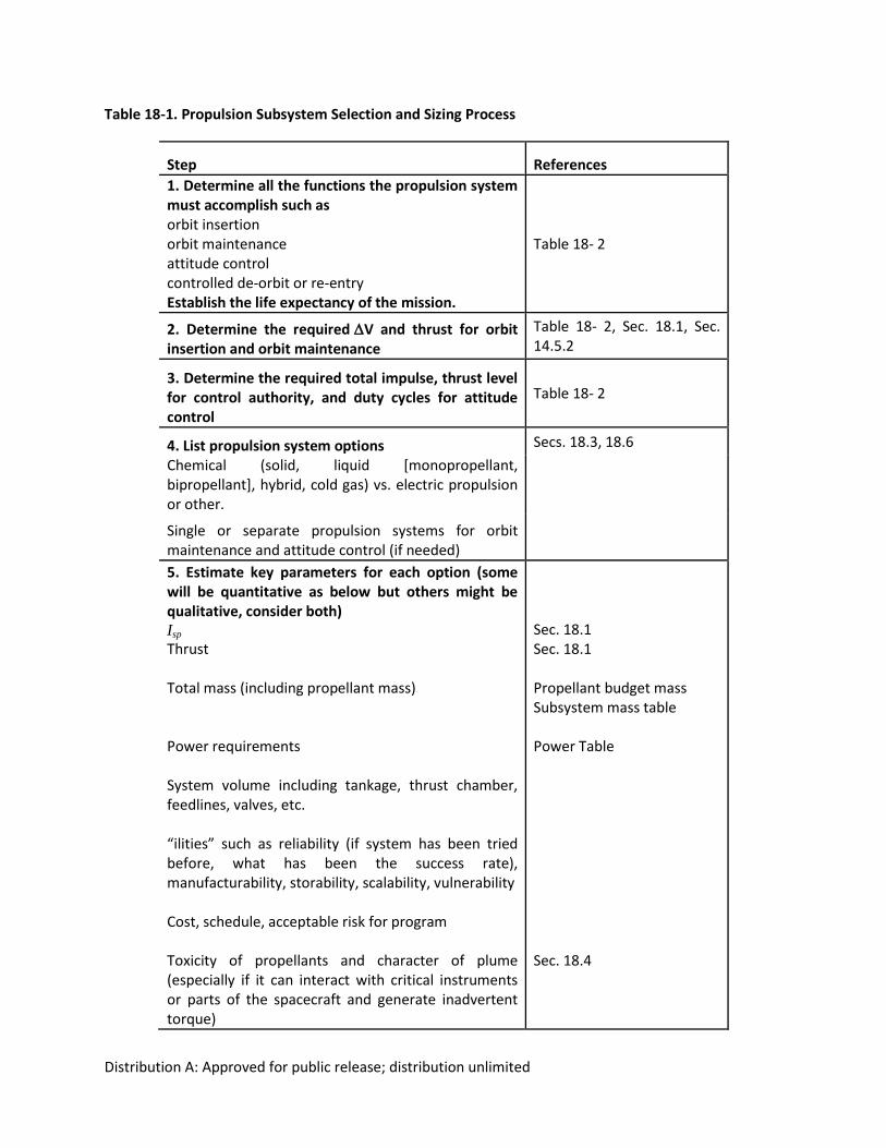
detailed discussion of this process see Humble [1995]. Table 18-1 lists a series of considerations for
determining the propulsion system for a given mission. In step 1 list all the functions the propulsion
system will have to fulfill for the duration of the mission, i.e. from orbit insertion to de-orbit. In steps 2
and 3 get quantitative details on performance requirements like V, thrust, and total impulse needed
from the propulsion system. In Step 4 list the available propulsion systems to meet the above
requirements. Don’t try to select a system at this point, just list the available options. In step 5, list all
the quantifiable figures of merit for the propulsion system, such as thrust, Isp, propellant mass,
propellant mass fraction and volume. Qualitative factors also have a big play on ranking different
propulsion systems. For example, a system which has been successfully used before and can meet the
requirements could directly provide a design solution. Also, if the people in the team have experience
with a particular rocket type, this might also play into the decision of which one to choose. In step 6,
reach a consensus with the team on what factors matter the most. Once the weight factors are
determined for each quantitative requirement, you can proceed to rank the different options and
choose a baseline in step 7. Document your decisions and how you arrived to them. More often than
not, as the design matures the requirements change, making you reconsider the choices for propulsion
systems. Keep flexibility in mind and be prepared for your design to change over time.
Distribution A: Approved for public release; distribution unlimited
Table 18-1. Propulsion Subsystem Selection and Sizing Process
Step References
1. Determine all the functions the propulsion system must accomplish such as orbit insertion orbit maintenance attitude control controlled de-orbit or re-entry Establish the life expectancy of the mission.
Table 18- 2
2. Determine the requiredV and thrust for orbit insertion and orbit maintenance
Table 18- 2, Sec. 18.1, Sec. 14.5.2
3. Determine the required total impulse, thrust level for control authority, and duty cycles for attitude control
Table 18- 2
4. List propulsion system options Secs. 18.3, 18.6
Chemical (solid, liquid [monopropellant, bipropellant], hybrid, cold gas) vs. electric propulsion or other.
Single or separate propulsion systems for orbit maintenance and attitude control (if needed)
5. Estimate key parameters for each option (some will be quantitative as below but others might be qualitative, consider both) Isp
Thrust Total mass (including propellant mass) Power requirements System volume including tankage, thrust chamber, feedlines, valves, etc. “ilities” such as reliability (if system has been tried before, what has been the success rate), manufacturability, storability, scalability, vulnerability Cost, schedule, acceptable risk for program Toxicity of propellants and character of plume (especially if it can interact with critical instruments or parts of the spacecraft and generate inadvertent torque)
Sec. 18.1 Sec. 18.1 Propellant budget mass Subsystem mass table Power Table Sec. 18.4
Distribution A: Approved for public release; distribution unlimited
6. Conduct Trade Studies
Choose a baseline propulsion system
Document trade results and the reasons for those results. Iterate the process as necessary
18.1 Basic rocket equations
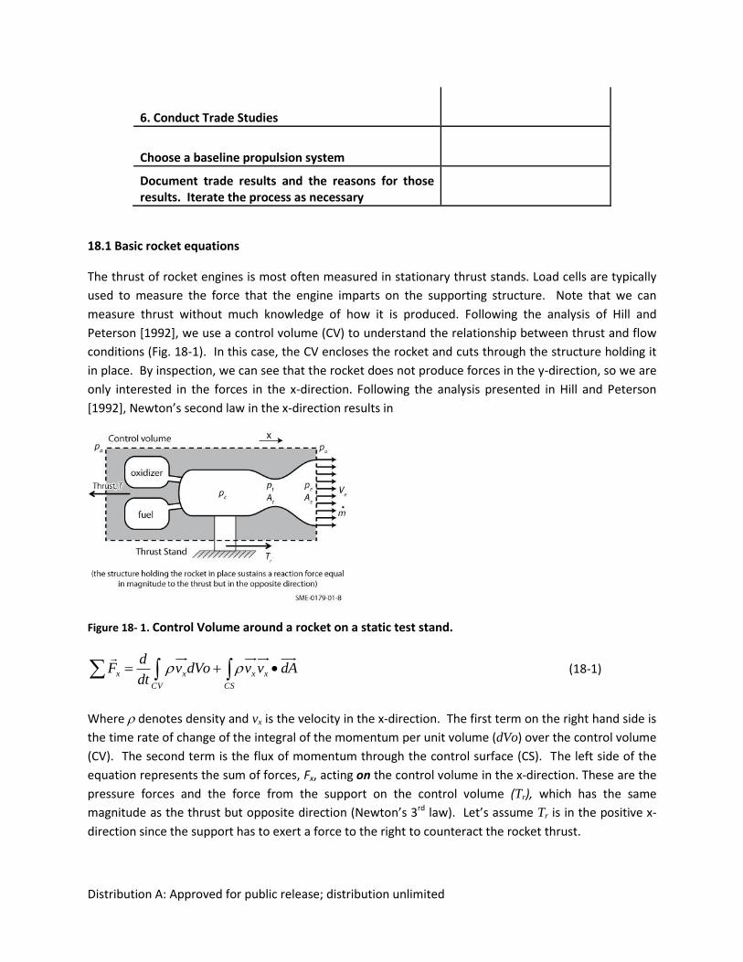
The thrust of rocket engines is most often measured in stationary thrust stands. Load cells are typically
used to measure the force that the engine imparts on the supporting structure. Note that we can
measure thrust without much knowledge of how it is produced. Following the analysis of Hill and
Peterson [1992], we use a control volume (CV) to understand the relationship between thrust and flow
conditions (Fig. 18-1). In this case, the CV encloses the rocket and cuts through the structure holding it
in place. By inspection, we can see that the rocket does not produce forces in the y-direction, so we are
only interested in the forces in the x-direction. Following the analysis presented in Hill and Peterson
[1992], Newton’s second law in the x-direction results in
Figure 18- 1. Control Volume around a rocket on a static test stand.
CV CS
xxxx dAvvdVovdt
dF
(18-1)
Where denotes density and vx is the velocity in the x-direction. The first term on the right hand side is
the time rate of change of the integral of the momentum per unit volume (dVo) over the control volume
(CV). The second term is the flux of momentum through the control surface (CS). The left side of the
equation represents the sum of forces, Fx, acting on the control volume in the x-direction. These are the
pressure forces and the force from the support on the control volume (Tr), which has the same
magnitude as the thrust but opposite direction (Newton’s 3rd law). Let’s assume Tr is in the positive x-
direction since the support has to exert a force to the right to counteract the rocket thrust.
Distribution A: Approved for public release; distribution unlimited
Evaluating the terms on the left and right hand sides of Eq. 18-1, and for the case of steady operation,
we have,
eeeear VmApApT
(18-2)
)( aeeer ppAVmT (Tr acts in the positive x-direction) (18-3)
where Ae is the exit area of the rocket nozzle, m is the mass flow rate being expelled through the nozzle
(mass the rocket is losing per unit time), pe and pa are the nozzle exit plane and ambient pressures
respectively, and Ve is the nozzle exhaust velocity. Since m Ve is positive and dominates over the second
term for practical operating conditions, the reaction force Tr will be in the positive x-direction.
The thrust, T, and the reaction force Tr have the same magnitude but act in opposite directions as
required by Newton’s 3rd law. The resulting expression for thrust is then:
)( aeee ppAVmT (T acts in the negative x-direction) (18-4)
Examining Eq. 18-4 we see from the first term that thrust depends on how much mass you eject from
the engine and the velocity it attains as it leaves the nozzle. The second term represents a mismatch
between the nozzle exit plane and the ambient pressures. As the rocket travels through the atmosphere
and pa changes, this force changes and it can add to or subtract from the thrust. For upper stage engines
and in-space propulsion systems pa is close to or equal to zero.
To increase thrust, we could increase Ve by using a larger nozzle exit area (Ae) while keeping the same
chamber temperature and pressure, chemical composition, and throat area. However, this would result
in a lower pe, which could have adverse effects if pe drops below pa. This is why large area ratios (Ae
/Athroat) are preferred in upper stage engines where the rocket is fired at very low values of atmospheric
pressure or at vacuum. However, we must make a trade-off between the extra thrust produced and the
additional weight of a larger nozzle.
For a fixed area ratio, we can increase Ve and thrust by increasing the chamber pressure or temperature,
which can be accomplished by changing the fuel/oxidizer mixture ratio or the propellants used.
Increasing the chamber pressure would require thicker (heavier) walls. Increasing the flame
temperature would require more cooling (which degrades performance) or more expensive materials.
Finally, we can augment thrust by increasing m . This could, however, imply a shorter burn time for a
given amount of propellants or more propellants to carry which would require larger and heavier tanks.
If we divide the thrust (Eq. 18-4) by the mass flow rate exhausting from the nozzle, we obtain the
equivalent or effective exhaust velocity, which is a measure of how efficiently the engine produces
thrust. Some authors denote this velocity as c.
eae
eeq Am
ppV
m
TV )(
(18-5)
Distribution A: Approved for public release; distribution unlimited
Note that when pe equals pa, Ve
equals Veq.
A relatively easy way to measure the performance of a rocket in a static stand is by measuring c*,
(pronounced c star) which is the characteristic exhaust velocity,
m
Apc tc
*
(18-6)
where pc is the chamber pressure and At
is the throat area. This is a measure of the efficiency of the
combustion. Note that it is independent of the nozzle design. Values for c* range from 1333 m/s for
hydrazine (N2H4), 1640 m/s for hypergolic systems of N2O4 and MMH (monomethylhydrazine), and up to
2360 m/s for liquid oxygen (LOX)-liquid hydrogen (LH2) systems. Experimental results, though, are
usually given in terms of c* efficiency against the theoretical values computed from thermochemistry.
Efficiency values (c*exper/c*theor) are usually in the range of 96-98%.
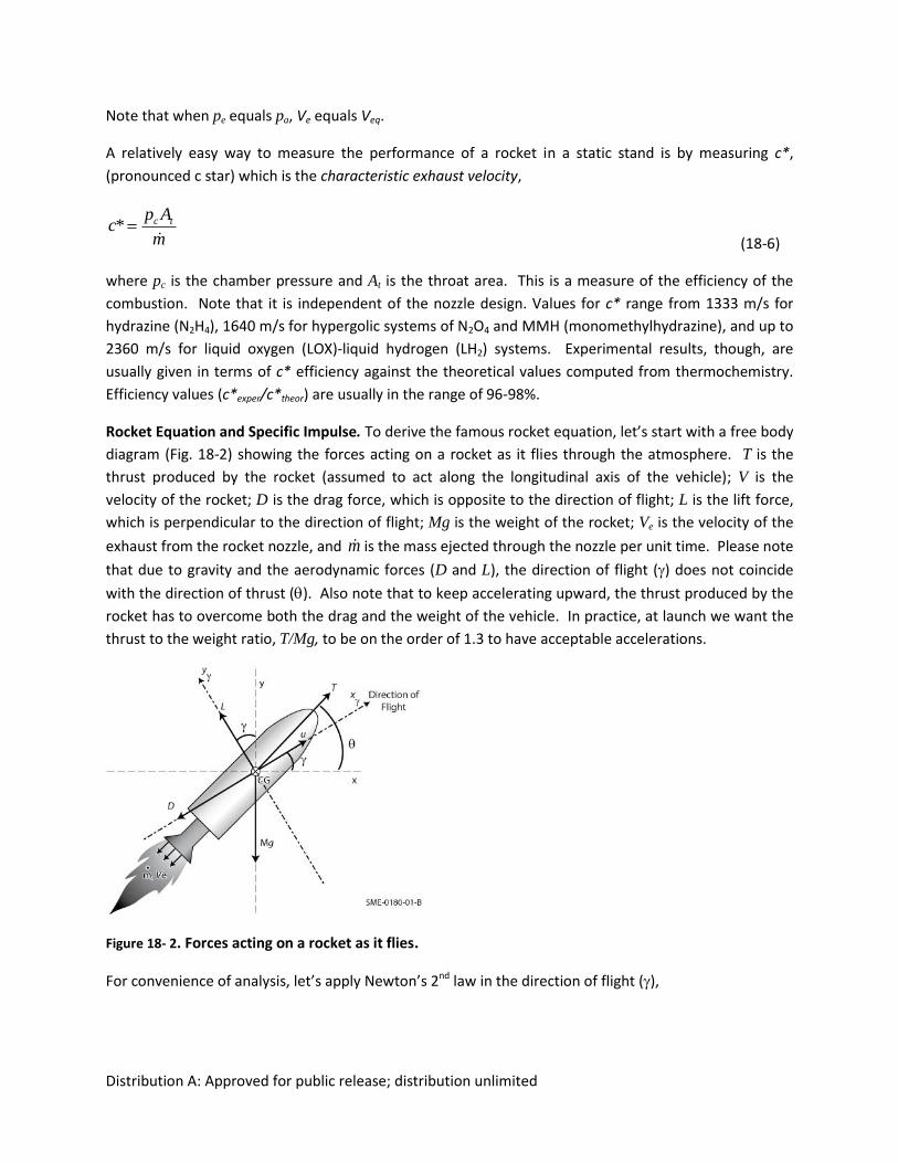
Rocket Equation and Specific Impulse. To derive the famous rocket equation, let’s start with a free body
diagram (Fig. 18-2) showing the forces acting on a rocket as it flies through the atmosphere. T is the
thrust produced by the rocket (assumed to act along the longitudinal axis of the vehicle); V is the
velocity of the rocket; D is the drag force, which is opposite to the direction of flight; L is the lift force,
which is perpendicular to the direction of flight; Mg is the weight of the rocket; Ve is the velocity of the
exhaust from the rocket nozzle, and m is the mass ejected through the nozzle per unit time. Please note
that due to gravity and the aerodynamic forces (D and L), the direction of flight () does not coincide
with the direction of thrust (). Also note that to keep accelerating upward, the thrust produced by the
rocket has to overcome both the drag and the weight of the vehicle. In practice, at launch we want the
thrust to the weight ratio, T/Mg, to be on the order of 1.3 to have acceptable accelerations.
Figure 18- 2. Forces acting on a rocket as it flies.
For convenience of analysis, let’s apply Newton’s 2nd law in the direction of flight (),
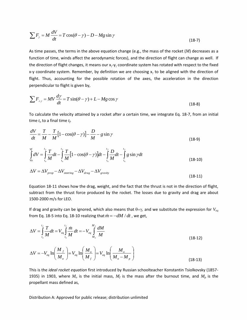
Distribution A: Approved for public release; distribution unlimited
sin)cos( MgDTdt
dVMF
(18-7)
As time passes, the terms in the above equation change (e.g., the mass of the rocket (M) decreases as a
function of time, winds affect the aerodynamic forces), and the direction of flight can change as well. If
the direction of flight changes, it means our x-y coordinate system has rotated with respect to the fixed
x-y coordinate system. Remember, by definition we are choosing x to be aligned with the direction of
flight. Thus, accounting for the possible rotation of the axes, the acceleration in the direction
perpendicular to flight is given by,
cos)sin( MgLT
dt
dMVF
(18-8)
To calculate the velocity attained by a rocket after a certain time, we integrate Eq. 18-7, from an initial
time to to a final time tf.
sin)cos(1 gM
D
M
T
M
T
dt
dV
(18-9)
dtgdtM
Ddt
M
Tdt
M
TdV
f
o
f
o
f
o
f
o
t
t
t
t
t
t
Vf
Vo
t
t
sin)cos(1 (18-10)
gravitydragsteeringprop VVVVV (18-11)
Equation 18-11 shows how the drag, weight, and the fact that the thrust is not in the direction of flight,
subtract from the thrust force produced by the rocket. The losses due to gravity and drag are about
1500-2000 m/s for LEO.
If drag and gravity can be ignored, which also means that and we substitute the expression for Veq
from Eq. 18-5 into Eq. 18-10 realizing that dtdMm / , we get,
f
o
f
o
f
o
M
M
eq
t
t
eq
t
tM
dMVdt
M
mVdt
M
TV
(18-12)
po
oeq
f
oeq
o
f
eqMM
MV
M
MV
M
MVV lnlnln
(18-13)
This is the ideal rocket equation first introduced by Russian schoolteacher Konstantin Tsiolkovsky (1857-
1935) in 1903, where Mo is the initial mass, Mf
is the mass after the burnout time, and Mp is the
propellant mass defined as,
Distribution A: Approved for public release; distribution unlimited
Mp = Mo - Mf (18-14)
The mass ratio has been defined by different authors as either Mf/Mo or Mo/Mf. We will be using the
rocket equation later in our examples section (18.8).
For solid rocket motors in particular, the total impulse, I, is an important performance parameter
defined as the integral of thrust, T, over the burn time, t,
t
dttTI0
)( (18-15)
This quantity is the energy released by a propulsion system. If the thrust is constant over the burn time,
the total impulse is simply the product of the thrust times the burn time.
The specific impulse, is usually defined as the total impulse normalized by the weight of the propellants.
For constant thrust force and uniform propellant mass flow rate the specific impulse reduces to,
o
eq
o
spg
V
gm
TI
(18-16)
where T is the thrust, m is the mass flow rate, and g0 is the gravitational constant at the Earth’s surface,
9.80665 m/s2, which gives a value of Isp expressed in seconds in SI units. The expression in terms of Veq
comes from using Eq. 18-5. The use of the constant g0 is in fact arbitrary, depending on whether the
total impulse was normalized by the mass or the weight of the propellants. It can be thought of as a
conversion factor and does not change where the gravitational acceleration is different. If omitted, Isp is
expressed in m/s and becomes the effective exhaust velocity of Eq. 18-5. Whether one uses g0 or not to
compute Isp has been matter of confusion in the rocket community so keep good track of units when
dealing with Isp values.
We can see that Isp is a measure of how efficiently we produce thrust. In a sense, it is similar to the
specific fuel consumption for a gas turbine or miles per gallon for a car. Analyzing the expression for Isp
(Eq. 18-16) we can see that higher values of Isp reduce the propellant rate needed to achieve a given
amount of thrust. For launch propulsion systems, thrust is more important than Isp because you must
have enough force to get off the ground and through the atmosphere. For upper stage engines and in-
space propulsion, Isp is more important because the weight has been significantly reduced and you want
to minimize the propellant you carry.
****************************Move to Side Bar all text in green *****************************
A simplified relationship between specific impulse, Isp, chamber temperature, Tc, and exhaust species
molecular weight, MW, is given by,
Distribution A: Approved for public release; distribution unlimited
*11
21
cp
pp
p
p
k
k
MW
TRI
c
aek
k
c
ecusp
(18-17)
where k is the ratio of the specific heats cp/cv (assumed constant for reactants and products). Usually
this ratio is denoted by but to avoid confusion with from Eqs. 18-7 to 10, it is denoted k in this
formula. Ru is the universal gas constant (8.314472 J/mol K), pe is the nozzle exhaust pressure, pc is the
combustion chamber pressure, pa is the ambient pressure,is the nozzle area expansion ratio; namely
the nozzle exit area divided by the throat area, Ae/At, and c* is the characteristic exhaust velocity
defined in Eq. (18-6). From this expression we see why it is preferred to have exhaust gases with low
molecular weight such as the water vapor produced when H2 and O2 are used as propellants. Also, we
see why the higher the combustion temperature the higher the specific impulse.
Substituting Eq. (18-16) into the ideal rocket equation (18-13) we obtain an expression in terms of Isp,
f
oosp
M
MgIV ln
(18-18)
where we can see that V is linear with Isp so any improvements on the specific impulse have a big
effect on V. Because the rocket equation is so widely used the following alternate forms, solving for
the propellant mass, can be very useful for preliminary design calculations as we will see in the examples
at the end of this Chapter.
)1(1//
ospe
gIV
f
VV
fp eMeMM (18-19)
)1(1// ospe
gIV
o
VV
op eMeMM
(18-20)
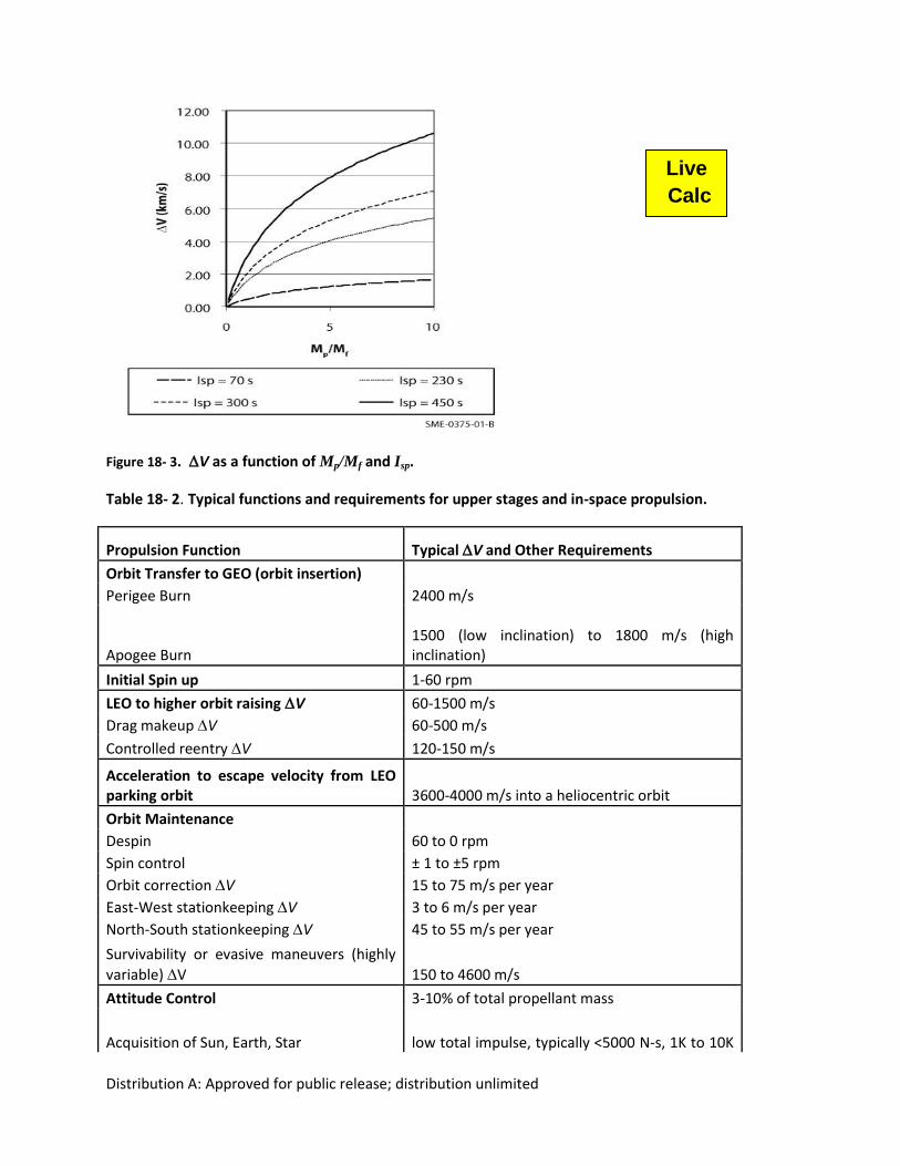
Figure 18-3 shows the effect on V from systems with different Isp values as a function of the ratio of the
propellant mass to the final mass after the propellant has been burned out, Mp/Mf. For launch vehicles
this ratio might approach 5-10 but for in-space propulsion it ranges from 0.2 to 1, showing how hard it is
to achieve the required V to at least reach LEO. In ascending order, the values of Isp selected are
representative of cold gas thrusters, monopropellant, solid and high performing liquid rockets, as we will
see later. We can see that the higher the Isp the higher the V achieved for a given mass ratio. Also, for a
given Isp, you want to maximize the mass ratio to achieve the largest V values.
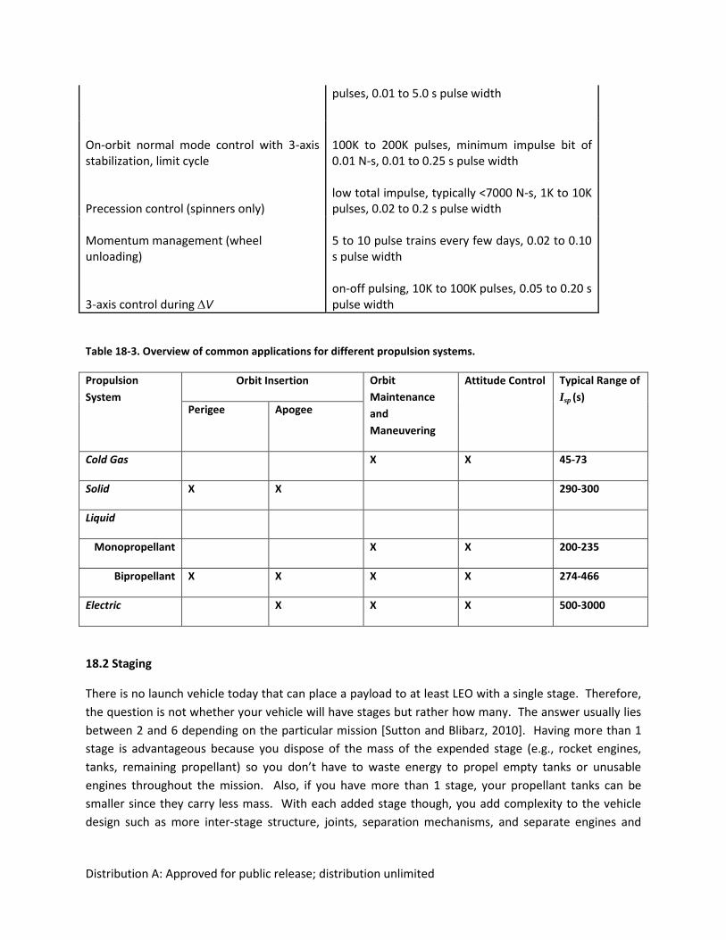
As a common practice, the requirements for a propulsion system are listed in terms of V, thrust, total
impulse, number of pulses and duration of the pulses from the rocket. Table 18- 2 shows typical
requirements for different functions a propulsion system has to execute. Table 18-3 serves as an
overview of how different propulsions systems, to be studied in the rest of this chapter, can be used for
different applications along with typical ranges for their Isp.
Distribution A: Approved for public release; distribution unlimited
Figure 18- 3. V as a function of Mp/Mf and Isp.
Table 18- 2. Typical functions and requirements for upper stages and in-space propulsion.
Propulsion Function Typical V and Other Requirements
Orbit Transfer to GEO (orbit insertion)
Perigee Burn 2400 m/s
Apogee Burn
1500 (low inclination) to 1800 m/s (high inclination)
Initial Spin up 1-60 rpm
LEO to higher orbit raisingV 60-1500 m/s
Drag makeup V 60-500 m/s
Controlled reentry V 120-150 m/s
Acceleration to escape velocity from LEO parking orbit 3600-4000 m/s into a heliocentric orbit
Orbit Maintenance
Despin 60 to 0 rpm
Spin control ± 1 to ±5 rpm
Orbit correction V 15 to 75 m/s per year
East-West stationkeeping V 3 to 6 m/s per year
North-South stationkeeping V 45 to 55 m/s per year
Survivability or evasive maneuvers (highly
variable) V 150 to 4600 m/s
Attitude Control 3-10% of total propellant mass
Acquisition of Sun, Earth, Star low total impulse, typically <5000 N-s, 1K to 10K
Live
Calc
Distribution A: Approved for public release; distribution unlimited
pulses, 0.01 to 5.0 s pulse width
On-orbit normal mode control with 3-axis stabilization, limit cycle
100K to 200K pulses, minimum impulse bit of 0.01 N-s, 0.01 to 0.25 s pulse width
Precession control (spinners only)
low total impulse, typically <7000 N-s, 1K to 10K pulses, 0.02 to 0.2 s pulse width
Momentum management (wheel unloading)
5 to 10 pulse trains every few days, 0.02 to 0.10 s pulse width
3-axis control during V
on-off pulsing, 10K to 100K pulses, 0.05 to 0.20 s pulse width
Table 18-3. Overview of common applications for different propulsion systems.
Propulsion
System
Orbit Insertion Orbit
Maintenance
and
Maneuvering
Attitude Control Typical Range of
Isp (s) Perigee Apogee
Cold Gas X X 45-73
Solid X X 290-300
Liquid
Monopropellant X X 200-235
Bipropellant X X X X 274-466
Electric X X X 500-3000
18.2 Staging
There is no launch vehicle today that can place a payload to at least LEO with a single stage. Therefore,
the question is not whether your vehicle will have stages but rather how many. The answer usually lies
between 2 and 6 depending on the particular mission [Sutton and Blibarz, 2010]. Having more than 1
stage is advantageous because you dispose of the mass of the expended stage (e.g., rocket engines,
tanks, remaining propellant) so you don’t have to waste energy to propel empty tanks or unusable
engines throughout the mission. Also, if you have more than 1 stage, your propellant tanks can be
smaller since they carry less mass. With each added stage though, you add complexity to the vehicle
design such as more inter-stage structure, joints, separation mechanisms, and separate engines and
Distribution A: Approved for public release; distribution unlimited
tanks. Therefore, it is recommended that you use as few stages as needed to achieve the mission
objectives.
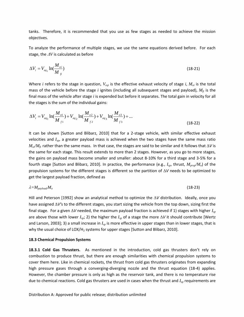
To analyze the performance of multiple stages, we use the same equations derived before. For each
stage, the V is calculated as before
)ln(fi
oi
ieqiM
MVV (18-21)
Where i refers to the stage in question, Veqi is the effective exhaust velocity of stage i, Moi is the total
mass of the vehicle before the stage i ignites (including all subsequent stages and payload), Mfi is the
final mass of the vehicle after stage i is expended but before it separates. The total gain in velocity for all
the stages is the sum of the individual gains:
...)ln()ln()ln(3
3
32
2
21
1
1
f
oeq
f
oeq
f
oeqt
M
MV
M
MV
M
MVV
(18-22)
It can be shown [Sutton and Blibarz, 2010] that for a 2-stage vehicle, with similar effective exhaust
velocities and Isp, a greater payload mass is achieved when the two stages have the same mass ratio
Moi/Mfi rather than the same mass. In that case, the stages are said to be similar and it follows that V is
the same for each stage. This result extends to more than 2 stages. However, as you go to more stages,
the gains on payload mass become smaller and smaller: about 8-10% for a third stage and 3-5% for a
fourth stage [Sutton and Blibarz, 2010]. In practice, the performance (e.g., Isp, thrust, Mprop/Mo) of the
propulsion systems for the different stages is different so the partition of V needs to be optimized to
get the largest payload fraction, defined as
=Mpayload/Mo (18-23)
Hill and Peterson [1992] show an analytical method to optimize the V distribution. Ideally, once you
have assigned V’s to the different stages, you start sizing the vehicle from the top down, sizing first the
final stage. For a given V needed, the maximum payload fraction is achieved if 1) stages with higher Isp
are above those with lower Isp; 2) the higher the Isp of a stage the more V it should contribute [Wertz
and Larson, 2003]; 3) a small increase in Isp is more effective in upper stages than in lower stages, that is
why the usual choice of LOX/H2 systems for upper stages [Sutton and Blibarz, 2010].
18.3 Chemical Propulsion Systems
18.3.1 Cold Gas Thrusters. As mentioned in the introduction, cold gas thrusters don’t rely on
combustion to produce thrust, but there are enough similarities with chemical propulsion systems to
cover them here. Like in chemical rockets, the thrust from cold gas thrusters originates from expanding
high pressure gases through a converging-diverging nozzle and the thrust equation (18-4) applies.
However, the chamber pressure is only as high as the reservoir tank, and there is no temperature rise
due to chemical reactions. Cold gas thrusters are used in cases when the thrust and Isp requirements are
Distribution A: Approved for public release; distribution unlimited
low and a small impulse bit is important. Generally they are used for total impulse up to about 22,000
N-s [Sutton and Blibarz, 2010]. Their main use is for attitude control and small V applications. The Isp of
the commonly used gases like He, N2, and Freon-14 are 165 s, 73 s, and 45 s respectively [Micci and
Ketsdever, 2000]. Hydrogen could also be used (Isp~ 272 s) but both H2 and He have the worst risk of
leaks because of the small size of the molecules. The main advantage of cold gas systems is their
simplicity. In a typical cold gas thruster system there are only valves, filters, regulators and relief valves
connecting the storage high pressure tank to the thruster (Fig. 18-8). Historic examples of systems using
cold gas propulsion systems include 1) the Viking Orbiter using N2 thrusters (Isp = 68 s) on its reaction
control system [Brown, 1996; Holmberg, 1980], 2) the Landsat 3 using Freon-14 thrusters for attitude
control [Brown, 1996; Landsat 1978] and 3) the manned maneuvering unit used by shuttle astronauts
for extra vehicular activities in 1984, which was powered by N2 cold gas thrusters [Bergonz, 1982]. Table
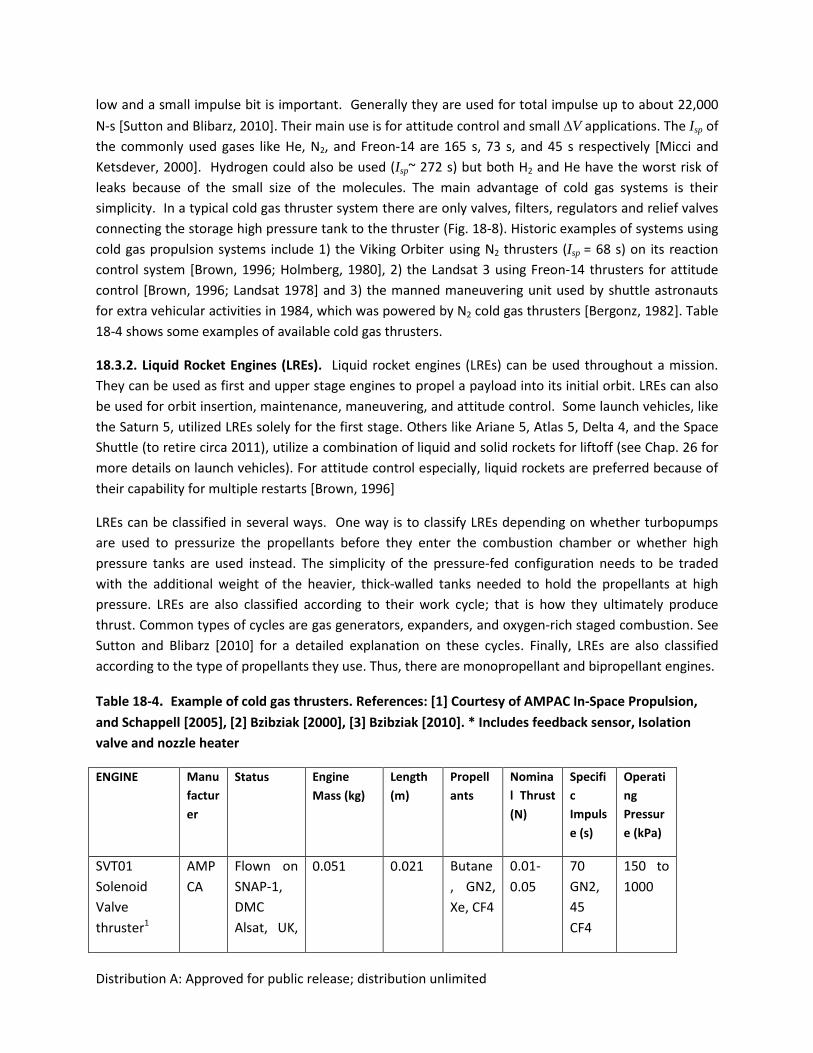
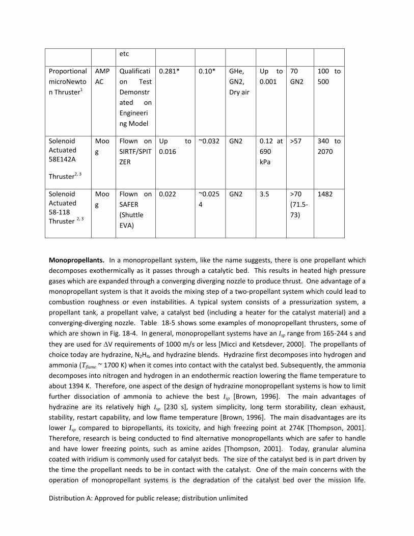
18-4 shows some examples of available cold gas thrusters.
18.3.2. Liquid Rocket Engines (LREs). Liquid rocket engines (LREs) can be used throughout a mission.
They can be used as first and upper stage engines to propel a payload into its initial orbit. LREs can also
be used for orbit insertion, maintenance, maneuvering, and attitude control. Some launch vehicles, like
the Saturn 5, utilized LREs solely for the first stage. Others like Ariane 5, Atlas 5, Delta 4, and the Space
Shuttle (to retire circa 2011), utilize a combination of liquid and solid rockets for liftoff (see Chap. 26 for
more details on launch vehicles). For attitude control especially, liquid rockets are preferred because of
their capability for multiple restarts [Brown, 1996]
LREs can be classified in several ways. One way is to classify LREs depending on whether turbopumps
are used to pressurize the propellants before they enter the combustion chamber or whether high
pressure tanks are used instead. The simplicity of the pressure-fed configuration needs to be traded
with the additional weight of the heavier, thick-walled tanks needed to hold the propellants at high
pressure. LREs are also classified according to their work cycle; that is how they ultimately produce
thrust. Common types of cycles are gas generators, expanders, and oxygen-rich staged combustion. See
Sutton and Blibarz [2010] for a detailed explanation on these cycles. Finally, LREs are also classified
according to the type of propellants they use. Thus, there are monopropellant and bipropellant engines.
Table 18-4. Example of cold gas thrusters. References: [1] Courtesy of AMPAC In-Space Propulsion,
and Schappell [2005], [2] Bzibziak [2000], [3] Bzibziak [2010]. * Includes feedback sensor, Isolation
valve and nozzle heater
ENGINE Manu
factur
er
Status Engine
Mass (kg)
Length
(m)
Propell
ants
Nomina
l Thrust
(N)
Specifi
c
Impuls
e (s)
Operati
ng
Pressur
e (kPa)
SVT01
Solenoid
Valve
thruster1
AMP
CA
Flown on
SNAP-1,
DMC
Alsat, UK,
0.051 0.021 Butane
, GN2,
Xe, CF4
0.01-
0.05
70
GN2,
45
CF4
150 to
1000
Distribution A: Approved for public release; distribution unlimited
etc
Proportional
microNewto
n Thruster1
AMP
AC
Qualificati
on Test
Demonstr
ated on
Engineeri
ng Model
0.281* 0.10* GHe,
GN2,
Dry air
Up to
0.001
70
GN2
100 to
500
Solenoid Actuated 58E142A
Thruster2, 3
Moo
g
Flown on
SIRTF/SPIT
ZER
Up to
0.016
~0.032 GN2 0.12 at
690
kPa
>57 340 to
2070
Solenoid Actuated 58-118 Thruster 2, 3
Moo
g
Flown on
SAFER
(Shuttle
EVA)
0.022 ~0.025
4
GN2 3.5 >70
(71.5-
73)
1482
Monopropellants. In a monopropellant system, like the name suggests, there is one propellant which
decomposes exothermically as it passes through a catalytic bed. This results in heated high pressure
gases which are expanded through a converging diverging nozzle to produce thrust. One advantage of a
monopropellant system is that it avoids the mixing step of a two-propellant system which could lead to
combustion roughness or even instabilities. A typical system consists of a pressurization system, a
propellant tank, a propellant valve, a catalyst bed (including a heater for the catalyst material) and a
converging-diverging nozzle. Table 18-5 shows some examples of monopropellant thrusters, some of
which are shown in Fig. 18-4. In general, monopropellant systems have an Isp range from 165-244 s and
they are used for V requirements of 1000 m/s or less [Micci and Ketsdever, 2000]. The propellants of
choice today are hydrazine, N2H4, and hydrazine blends. Hydrazine first decomposes into hydrogen and
ammonia (Tflame ~ 1700 K) when it comes into contact with the catalyst bed. Subsequently, the ammonia
decomposes into nitrogen and hydrogen in an endothermic reaction lowering the flame temperature to
about 1394 K. Therefore, one aspect of the design of hydrazine monopropellant systems is how to limit
further dissociation of ammonia to achieve the best Isp [Brown, 1996]. The main advantages of
hydrazine are its relatively high Isp [230 s], system simplicity, long term storability, clean exhaust,
stability, restart capability, and low flame temperature [Brown, 1996]. The main disadvantages are its
lower Isp compared to bipropellants, its toxicity, and high freezing point at 274K [Thompson, 2001].
Therefore, research is being conducted to find alternative monopropellants which are safer to handle
and have lower freezing points, such as amine azides [Thompson, 2001]. Today, granular alumina
coated with iridium is commonly used for catalyst beds. The size of the catalyst bed is in part driven by
the time the propellant needs to be in contact with the catalyst. One of the main concerns with the
operation of monopropellant systems is the degradation of the catalyst bed over the mission life.
Distribution A: Approved for public release; distribution unlimited
Degradation is a function of the total amount of propellant used, mass flow rate or operating pressure,
number and size of thermal cycles, and number of pulses.1 Catalyst bed heaters are almost always used
to preheat the bed prior to operation in order to increase bed life and to also decrease the ignition
delay. Monopropellant systems used for attitude control need to be able to restart multiple times. How
quickly thrust can be generated is also important. Other factors to consider when designing a
monopropellant system are how fast the valve responds, how fast the catalyst heats up so that it can
promote decomposition of the propellant, and how fast the pressure rises [Brown, 1996].
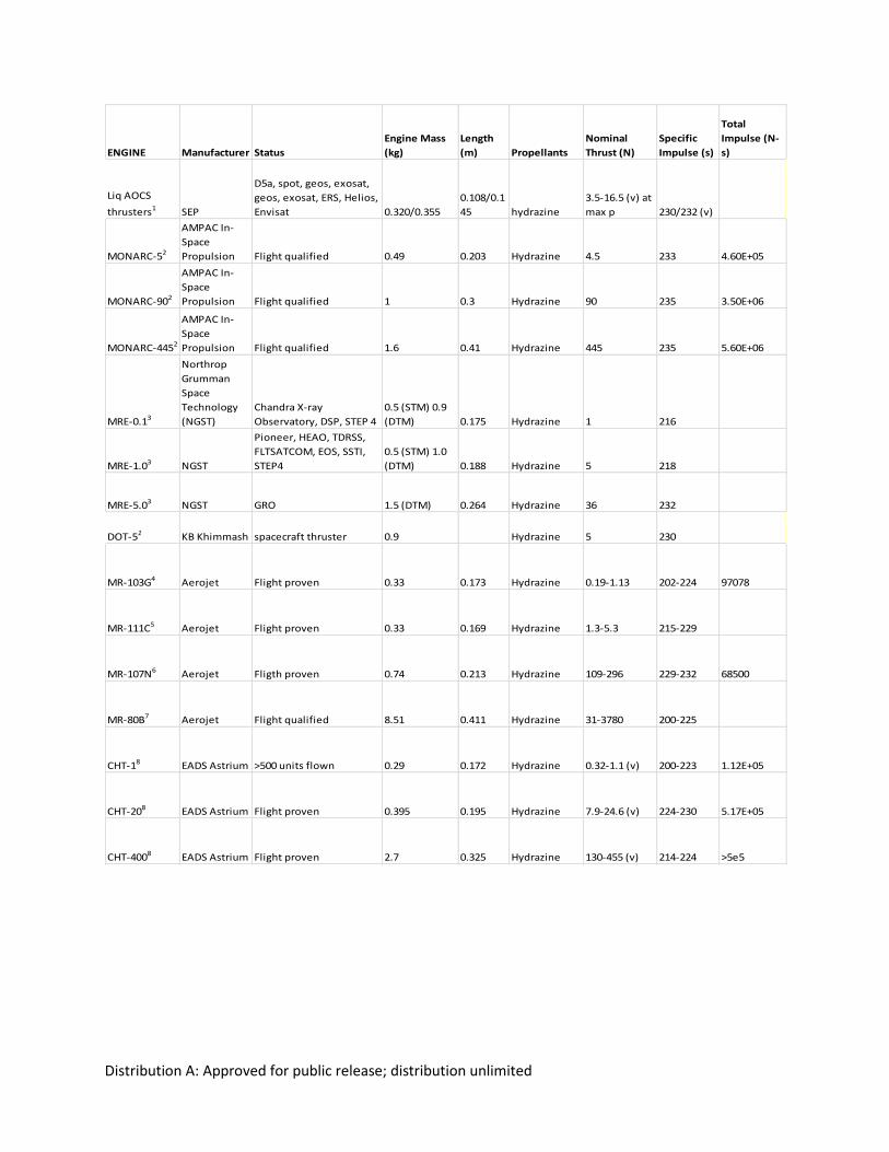
Table 18-5. Representative Monopropellant Systems. References: [1] Sweetman [2006], [2] Courtesy
of AMPAC In-Space Propulsion, [3] Northrop [2010a], [4] McRight [2005], [5] Swink [1999], [6] Frei
[2001], [7] Morrisey [1992] and Dawnson [2007], [8] Astrium [2010b]. (v)= vacuum
1 As a note, because of the smaller mass flow rates, microsatellites (10-100 kg) will likely incur less degradation
[Ketsdever, 2006].
Distribution A: Approved for public release; distribution unlimited
ENGINE Manufacturer Status
Engine Mass
(kg)
Length
(m) Propellants
Nominal
Thrust (N)
Specific
Impulse (s)
Total
Impulse (N-
s)
Liq AOCS
thrusters1 SEP
D5a, spot, geos, exosat,
geos, exosat, ERS, Helios,
Envisat 0.320/0.355
0.108/0.1
45 hydrazine
3.5-16.5 (v) at
max p 230/232 (v)
MONARC-52
AMPAC In-
Space
Propulsion Flight qualified 0.49 0.203 Hydrazine 4.5 233 4.60E+05
MONARC-902
AMPAC In-
Space
Propulsion Flight qualified 1 0.3 Hydrazine 90 235 3.50E+06
MONARC-4452
AMPAC In-
Space
Propulsion Flight qualified 1.6 0.41 Hydrazine 445 235 5.60E+06
MRE-0.13
Northrop
Grumman
Space
Technology
(NGST)
Chandra X-ray
Observatory, DSP, STEP 4
0.5 (STM) 0.9
(DTM) 0.175 Hydrazine 1 216
MRE-1.03 NGST
Pioneer, HEAO, TDRSS,
FLTSATCOM, EOS, SSTI,
STEP4
0.5 (STM) 1.0
(DTM) 0.188 Hydrazine 5 218
MRE-5.03 NGST GRO 1.5 (DTM) 0.264 Hydrazine 36 232
DOT-51 KB Khimmash spacecraft thruster 0.9 Hydrazine 5 230
MR-103G4 Aerojet Flight proven 0.33 0.173 Hydrazine 0.19-1.13 202-224 97078
MR-111C5 Aerojet Flight proven 0.33 0.169 Hydrazine 1.3-5.3 215-229
MR-107N6 Aerojet Fligth proven 0.74 0.213 Hydrazine 109-296 229-232 68500
MR-80B7 Aerojet Flight qualified 8.51 0.411 Hydrazine 31-3780 200-225
CHT-18 EADS Astrium >500 units flown 0.29 0.172 Hydrazine 0.32-1.1 (v) 200-223 1.12E+05
CHT-208 EADS Astrium Flight proven 0.395 0.195 Hydrazine 7.9-24.6 (v) 224-230 5.17E+05
CHT-4008 EADS Astrium Flight proven 2.7 0.325 Hydrazine 130-455 (v) 214-224 >5e5
Distribution A: Approved for public release; distribution unlimited
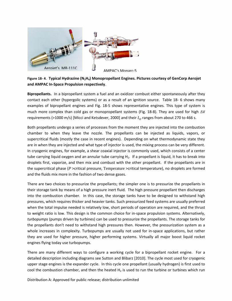
Figure 18- 4. Typical Hydrazine (N2H4) Monopropellant Engines. Pictures courtesy of GenCorp Aerojet
and AMPAC In-Space Propulsion respectively.
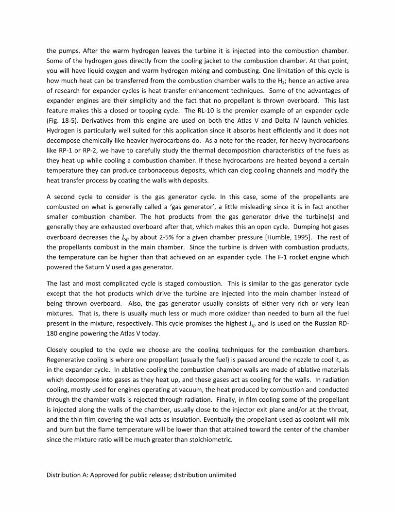
Bipropellants. In a bipropellant system a fuel and an oxidizer combust either spontaneously after they
contact each other (hypergolic systems) or as a result of an ignition source. Table 18- 6 shows many
examples of bipropellant engines and Fig. 18-5 shows representative engines. This type of system is
much more complex than cold gas or monopropellant systems (Fig. 18-8). They are used for high V
requirements (>1000 m/s) [Micci and Ketsdever, 2000] and their Isp ranges from about 270 to 466 s.
Both propellants undergo a series of processes from the moment they are injected into the combustion
chamber to when they leave the nozzle. The propellants can be injected as liquids, vapors, or
supercritical fluids (mostly the case in recent engines). Depending on what thermodynamic state they
are in when they are injected and what type of injector is used, the mixing process can be very different.
In cryogenic engines, for example, a shear coaxial injector is commonly used, which consists of a center
tube carrying liquid oxygen and an annular tube carrying H2. If a propellant is liquid, it has to break into
droplets first, vaporize, and then mix and combust with the other propellant. If the propellants are in
the supercritical phase (P >critical pressure, Temperature >critical temperature), no droplets are formed
and the fluids mix more in the fashion of two dense gases.
There are two choices to pressurize the propellants; the simpler one is to pressurize the propellants in
their storage tank by means of a high pressure inert fluid. The high pressure propellant then discharges
into the combustion chamber. In this case, the storage tanks have to be designed to withstand high
pressures, which requires thicker and heavier tanks. Such pressurized feed systems are usually preferred
when the total impulse needed is relatively low, short periods of operation are required, and the thrust
to weight ratio is low. This design is the common choice for in-space propulsion systems. Alternatively,
turbopumps (pumps driven by turbines) can be used to pressurize the propellants. The storage tanks for
the propellants don’t need to withstand high pressures then. However, the pressurization system as a
whole increases in complexity. Turbopumps are usually not used for in-space applications, but rather
they are used for higher pressure, higher performing systems. Virtually all major boost liquid rocket
engines flying today use turbopumps.
There are many different ways to configure a working cycle for a bipropellant rocket engine. For a
detailed description including diagrams see Sutton and Blibarz [2010]. The cycle most used for cryogenic
upper stage engines is the expander cycle. In this cycle one propellant (usually hydrogen) is first used to
cool the combustion chamber, and then the heated H2 is used to run the turbine or turbines which run
Aerojet’s MR-111C AMPAC’s Monarc-5
Distribution A: Approved for public release; distribution unlimited
the pumps. After the warm hydrogen leaves the turbine it is injected into the combustion chamber.
Some of the hydrogen goes directly from the cooling jacket to the combustion chamber. At that point,
you will have liquid oxygen and warm hydrogen mixing and combusting. One limitation of this cycle is
how much heat can be transferred from the combustion chamber walls to the H2; hence an active area
of research for expander cycles is heat transfer enhancement techniques. Some of the advantages of
expander engines are their simplicity and the fact that no propellant is thrown overboard. This last
feature makes this a closed or topping cycle. The RL-10 is the premier example of an expander cycle
(Fig. 18-5). Derivatives from this engine are used on both the Atlas V and Delta IV launch vehicles.
Hydrogen is particularly well suited for this application since it absorbs heat efficiently and it does not
decompose chemically like heavier hydrocarbons do. As a note for the reader, for heavy hydrocarbons
like RP-1 or RP-2, we have to carefully study the thermal decomposition characteristics of the fuels as
they heat up while cooling a combustion chamber. If these hydrocarbons are heated beyond a certain
temperature they can produce carbonaceous deposits, which can clog cooling channels and modify the
heat transfer process by coating the walls with deposits.
A second cycle to consider is the gas generator cycle. In this case, some of the propellants are
combusted on what is generally called a ‘gas generator’, a little misleading since it is in fact another
smaller combustion chamber. The hot products from the gas generator drive the turbine(s) and
generally they are exhausted overboard after that, which makes this an open cycle. Dumping hot gases
overboard decreases the Isp by about 2-5% for a given chamber pressure [Humble, 1995]. The rest of
the propellants combust in the main chamber. Since the turbine is driven with combustion products,
the temperature can be higher than that achieved on an expander cycle. The F-1 rocket engine which
powered the Saturn V used a gas generator.
The last and most complicated cycle is staged combustion. This is similar to the gas generator cycle
except that the hot products which drive the turbine are injected into the main chamber instead of
being thrown overboard. Also, the gas generator usually consists of either very rich or very lean
mixtures. That is, there is usually much less or much more oxidizer than needed to burn all the fuel
present in the mixture, respectively. This cycle promises the highest Isp and is used on the Russian RD-
180 engine powering the Atlas V today.
Closely coupled to the cycle we choose are the cooling techniques for the combustion chambers.
Regenerative cooling is where one propellant (usually the fuel) is passed around the nozzle to cool it, as
in the expander cycle. In ablative cooling the combustion chamber walls are made of ablative materials
which decompose into gases as they heat up, and these gases act as cooling for the walls. In radiation
cooling, mostly used for engines operating at vacuum, the heat produced by combustion and conducted
through the chamber walls is rejected through radiation. Finally, in film cooling some of the propellant
is injected along the walls of the chamber, usually close to the injector exit plane and/or at the throat,
and the thin film covering the wall acts as insulation. Eventually the propellant used as coolant will mix
and burn but the flame temperature will be lower than that attained toward the center of the chamber
since the mixture ratio will be much greater than stoichiometric.
Distribution A: Approved for public release; distribution unlimited
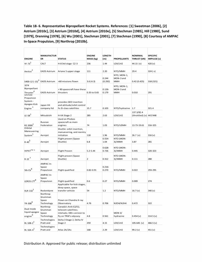
Table 18- 6. Representative Bipropellant Rocket Systems. References: [1] Sweetman [2006], [2]
Astrium [2010c], [3] Astrium [2010d], [4] Astrium [2010e], [5] Stechman [1985], Hill [1980], Sund
[1979], Drenning [1978], [6] Wu [2001], Stechman [2001], [7] Stechman [1990], [8] Courtesy of AMPAC
In-Space Propulsion, [9] Northrop [2010b].
ENGINE
MANUFACTUR
ER STATUS
ENGINE
MASS (kg)
LENGTH
(m) PROPELLANTS
NOMINAL
THRUST (kN)
SPECIFIC
IMPULSE (s)
YF-731
CALT H-8 3rd stage CZ-3 236 1.44 LOX/LH2 44.15 (v) 420 (v)
Aestus2
EADS Astrium Ariane 5 upper stage 111 2.20 NTO/MMH 29.4 324 ( v)
S400-12 (-15)3
EADS Astrium >60 missions flown 3.6 (4.3)
0.244
(0.292)
NTO, MON-1,
MON-3 and
MMH 0.42 (0.425) 318 (321)
10 N
Bipropellant
Thruster4
EADS Astrium
> 90 spacecraft have these
thrusters 0.35 to 0.65
0.126-
0.179
NTO, MON-1,
MON-3 and
MMH 0.010 291Unified
Propulsion
System -
Apogee Kick
Engine 1
Japan IHI
company ltd
provides GEO insertion
and attitude/orbit control
fo 2t-class satellites 15.7 0.103 NTO/hydrazine 1.7 321.4
LE-5B1
Mitsubishi H-IIA Stage 2 285 2.63 LOX/LH2
137.3/82.4
(throttled) (v) 447/448
R2.20001
Russian
Federation
Used on Phobos
spacecraft as main
engines 74 1.03 NTO/UDMH 13.73-19.61 316-325Orbital
Maneuvering
System1
Aerojet
Shuttle: orbit insertion,
manuevering, and reentry
initiation 118 1.96 NTO/MMH 26.7 (v) 316 (v)
R-405
Aerojet
Flight proven (Space
Shuttle) 6.8
0.554-
1.04
NTO (MON-
3)/MMH 3.87 281
HiPATTM 6 Aerojet Flight Proven 5.2-5.44
0.628-
0.726
NTO (MON-
3)/MMH 0.445 320-323
R-1E 7
Aerojet
Flight proven (Space
Shuttle) 2 0.312
NTO (MON-
3)/MMH 0.111 280
5lb Cb8
AMPAC In-
Space
Propulsion Flight qualified 0.82-0.91
0.216-
0.270 NTO/MMH 0.022 293-295
LEROS LTT8
AMPAC In-
Space
Propulsion Flight qualified 0.6 0.27 NTO/MMH 0.009 274
XLR-1321
Rocketdyne
Applicable for kick stages,
deep space, space
transfer vehicle 54 1.2 NTO/MMH 16.7 (v) 340 (v)
TR-3089
Northrop
Grumman
Space
Technology
Flown on Chandra X-ray
Observatory 4.76 0.706 N2O4/N2H4 0.472 322
Dual mode
liquid apogee
engine9
Northrop
Grumman
Space
Technology
Canada's Anik E2/E1;
telecom satellites;
intelsats; 330 s version to
fly on TRW's odyssey 4.8 0.561
MON 3/
hydrazine 0.454 (v) 314.5 (v)
RL 10B-21
United
Technologies
Pratt and
Delta 3 Stage 2, Delta IV
Stage 2 259 4.15 LOX/LH2 105.645 (v) 466.5 (v)
RL 10A-41
United
Technologies
Pratt and Atlas 2A/2As 168 2.29 LOX/LH2 99.2 (v) 451 (v)
Distribution A: Approved for public release; distribution unlimited
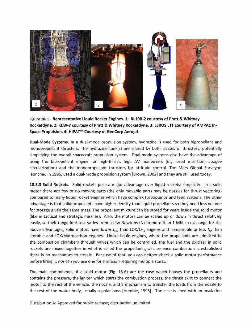
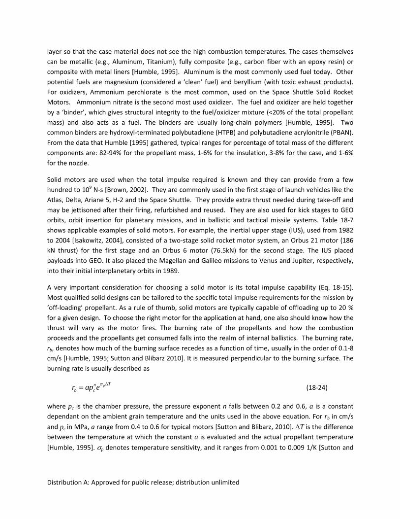
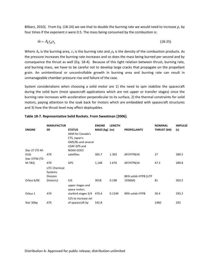
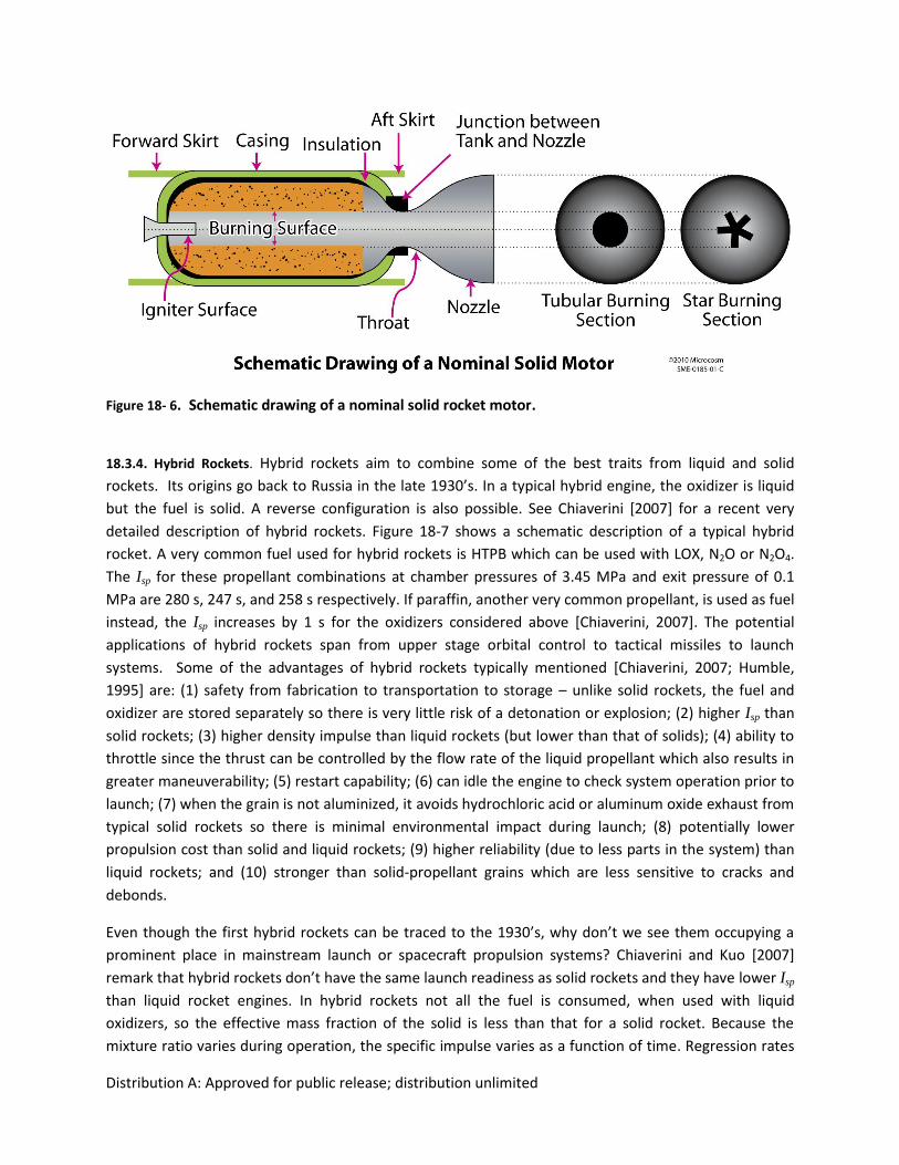
Figure 18- 5. Representative Liquid Rocket Engines. 1: RL10B-2 courtesy of Pratt & Whitney
Rocketdyne, 2: KEW-7 courtesy of Pratt & Whitney Rocketdyne, 3: LEROS LTT courtesy of AMPAC In-
Space Propulsion, 4: HiPAT™ Courtesy of GenCorp Aerojet.
Dual-Mode Systems. In a dual-mode propulsion system, hydrazine is used for both bipropellant and
monopropellant thrusters. The hydrazine tank(s) are shared by both classes of thrusters, potentially
simplifying the overall spacecraft propulsion system. Dual-mode systems also have the advantage of
using the bipropellant engine for high-thrust, high V maneuvers (e.g. orbit insertion, apogee
circularization) and the monopropellant thrusters for attitude control. The Mars Global Surveyor,
launched in 1996, used a dual-mode propulsion system [Brown, 2002] and they are still used today.
18.3.3 Solid Rockets. Solid rockets pose a major advantage over liquid rockets: simplicity. In a solid
motor there are few or no moving parts (the only movable parts may be nozzles for thrust vectoring)
compared to many liquid rocket engines which have complex turbopumps and feed systems. The other
advantage is that solid propellants have higher density than liquid propellants so they need less volume
for storage given the same mass. The propellant mixture can be stored for years inside the solid motor
(like in tactical and strategic missiles). Also, the motors can be scaled up or down in thrust relatively
easily, so their range in thrust varies from a few Newtons (N) to more than 1 MN. In exchange for the
above advantages, solid motors have lower Isp, than LOX/LH2 engines and comparable or less Isp than
storable and LOX/hydrocarbon engines. Unlike liquid engines, where the propellants are admitted to
the combustion chambers through valves which can be controlled, the fuel and the oxidizer in solid
rockets are mixed together in what is called the propellant grain, so once combustion is established
there is no mechanism to stop it. Because of that, you can neither check a solid motor performance
before firing it, nor can you use one for a mission requiring multiple starts.
The main components of a solid motor (Fig. 18-6) are the case which houses the propellants and
contains the pressure, the igniter which starts the combustion process, the thrust skirt to connect the
motor to the rest of the vehicle, the nozzle, and a mechanism to transfer the loads from the nozzle to
the rest of the motor body, usually a polar boss [Humble, 1995]. The case is lined with an insulation
1 2 3 4
Distribution A: Approved for public release; distribution unlimited
layer so that the case material does not see the high combustion temperatures. The cases themselves
can be metallic (e.g., Aluminum, Titanium), fully composite (e.g., carbon fiber with an epoxy resin) or
composite with metal liners [Humble, 1995]. Aluminum is the most commonly used fuel today. Other
potential fuels are magnesium (considered a ‘clean’ fuel) and beryllium (with toxic exhaust products).
For oxidizers, Ammonium perchlorate is the most common, used on the Space Shuttle Solid Rocket
Motors. Ammonium nitrate is the second most used oxidizer. The fuel and oxidizer are held together
by a ‘binder’, which gives structural integrity to the fuel/oxidizer mixture (<20% of the total propellant
mass) and also acts as a fuel. The binders are usually long-chain polymers [Humble, 1995]. Two
common binders are hydroxyl-terminated polybutadiene (HTPB) and polybutadiene acrylonitrile (PBAN).
From the data that Humble [1995] gathered, typical ranges for percentage of total mass of the different
components are: 82-94% for the propellant mass, 1-6% for the insulation, 3-8% for the case, and 1-6%
for the nozzle.
Solid motors are used when the total impulse required is known and they can provide from a few
hundred to 109 N-s [Brown, 2002]. They are commonly used in the first stage of launch vehicles like the
Atlas, Delta, Ariane 5, H-2 and the Space Shuttle. They provide extra thrust needed during take-off and
may be jettisoned after their firing, refurbished and reused. They are also used for kick stages to GEO
orbits, orbit insertion for planetary missions, and in ballistic and tactical missile systems. Table 18-7
shows applicable examples of solid motors. For example, the inertial upper stage (IUS), used from 1982
to 2004 [Isakowitz, 2004], consisted of a two-stage solid rocket motor system, an Orbus 21 motor (186
kN thrust) for the first stage and an Orbus 6 motor (76.5kN) for the second stage. The IUS placed
payloads into GEO. It also placed the Magellan and Galileo missions to Venus and Jupiter, respectively,
into their initial interplanetary orbits in 1989.
A very important consideration for choosing a solid motor is its total impulse capability (Eq. 18-15).
Most qualified solid designs can be tailored to the specific total impulse requirements for the mission by
‘off-loading’ propellant. As a rule of thumb, solid motors are typically capable of offloading up to 20 %
for a given design. To choose the right motor for the application at hand, one also should know how the
thrust will vary as the motor fires. The burning rate of the propellants and how the combustion
proceeds and the propellants get consumed falls into the realm of internal ballistics. The burning rate,
rb, denotes how much of the burning surface recedes as a function of time, usually in the order of 0.1-8
cm/s [Humble, 1995; Sutton and Blibarz 2010]. It is measured perpendicular to the burning surface. The
burning rate is usually described as
Tn
cbpeapr
(18-24)
where pc is the chamber pressure, the pressure exponent n falls between 0.2 and 0.6, a is a constant
dependant on the ambient grain temperature and the units used in the above equation. For rb in cm/s
and pc in MPa, a range from 0.4 to 0.6 for typical motors [Sutton and Blibarz, 2010]. T is the difference
between the temperature at which the constant a is evaluated and the actual propellant temperature
[Humble, 1995]. p denotes temperature sensitivity, and it ranges from 0.001 to 0.009 1/K [Sutton and
Distribution A: Approved for public release; distribution unlimited
Blibarz, 2010]. From Eq. (18-24) we see that to double the burning rate we would need to increase pc by
four times if the exponent n were 0.5. The mass being consumed by the combustion is:
bbbrAm (18-25)
Where Ab is the burning area, rb is the burning rate and b is the density of the combustion products. As
the pressure increases the burning rate increases and so does the mass being burned per second and by
consequence the thrust as well (Eq. 18-4). Because of this tight relation between thrust, burning rate,
and burning mass, we have to be careful not to develop large cracks that propagate on the propellant
grain. An unintentional or uncontrollable growth in burning area and burning rate can result in
unmanageable chamber pressure rise and failure of the case.
System considerations when choosing a solid motor are 1) the need to spin stabilize the spacecraft
during the solid burn (most spacecraft applications which are not upper or transfer stages) since the
burning rate increases with acceleration perpendicular to its surface, 2) the thermal constraints for solid
motors, paying attention to the soak back for motors which are embedded with spacecraft structures
and 3) how the thrust level may affect deployables.
Table 18-7. Representative Solid Rockets. From Sweetman [2006].
ENGINE
MANUFACTUR
ER STATUS
ENGINE
MASS (kg)
LENGTH
(m) PROPELLANTS
NOMINAL
THRUST (kN)
SPECIFIC
IMPULSE
(s)
Star 27 (TE-M-
616) ATK
AKM for Canada's
CTS, Japan's
GMS/Bs and several
USAF GPS and
NOAA GOES
satellites 365.7 1.303 AP/HTPB/Al 27 289.5
Star 37FM (TE-
M-783) ATK GPS 1,148 1.676 AP/HTPB/Al 47.3 289.8
Orbus 6/6E
UTC Chemical
Systems
Division
(historic) IUS 3018 0.198
86% solids HTPB (UTP
19360A) 81 303.5
Orbus 1 ATK
upper stages and
space motor;
starbird stages 3/4 470.4 0.1249 90% solids HTPB 30.4 293.3
Star 30bp ATK
used in contour p.
525 to increase vel
of spacecraft by 542.8 1460 292
Distribution A: Approved for public release; distribution unlimited
Figure 18- 6. Schematic drawing of a nominal solid rocket motor.
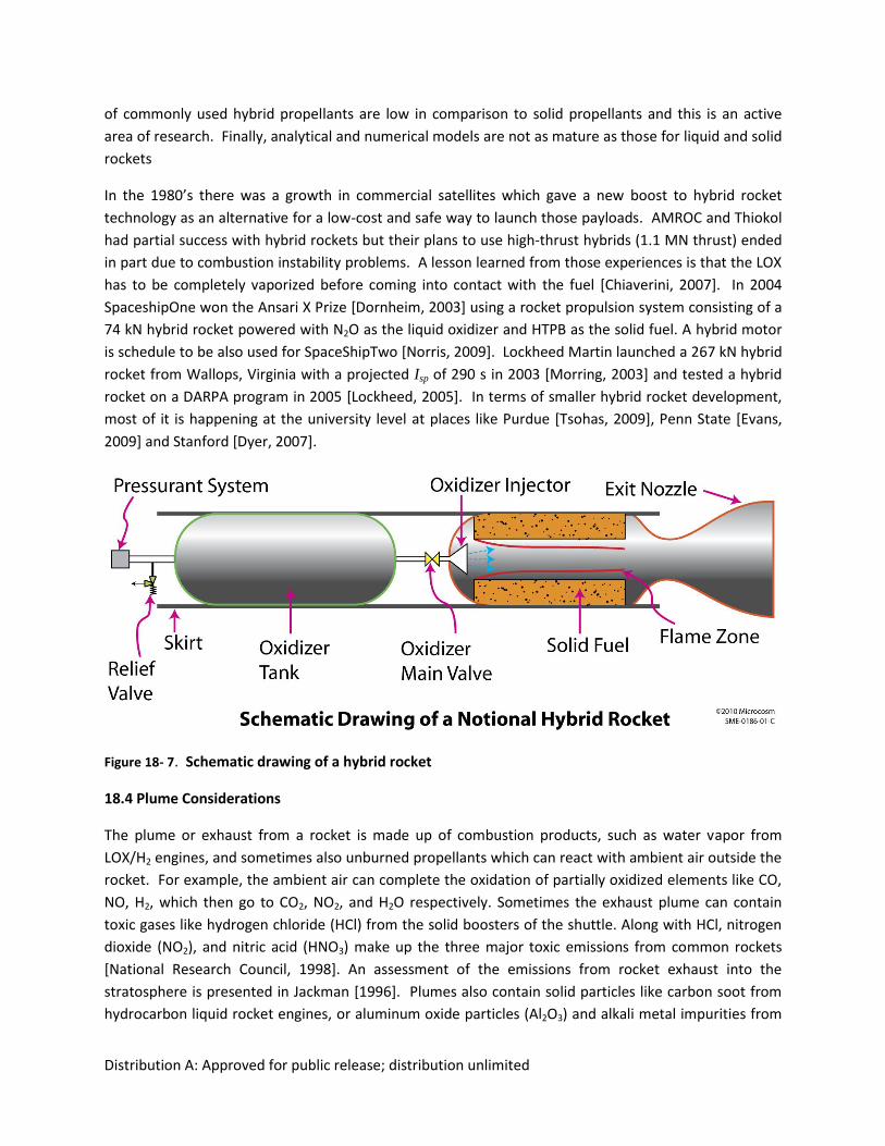
18.3.4. Hybrid Rockets. Hybrid rockets aim to combine some of the best traits from liquid and solid
rockets. Its origins go back to Russia in the late 1930’s. In a typical hybrid engine, the oxidizer is liquid
but the fuel is solid. A reverse configuration is also possible. See Chiaverini [2007] for a recent very
detailed description of hybrid rockets. Figure 18-7 shows a schematic description of a typical hybrid
rocket. A very common fuel used for hybrid rockets is HTPB which can be used with LOX, N2O or N2O4.
The Isp for these propellant combinations at chamber pressures of 3.45 MPa and exit pressure of 0.1
MPa are 280 s, 247 s, and 258 s respectively. If paraffin, another very common propellant, is used as fuel
instead, the Isp increases by 1 s for the oxidizers considered above [Chiaverini, 2007]. The potential
applications of hybrid rockets span from upper stage orbital control to tactical missiles to launch
systems. Some of the advantages of hybrid rockets typically mentioned [Chiaverini, 2007; Humble,
1995] are: (1) safety from fabrication to transportation to storage – unlike solid rockets, the fuel and
oxidizer are stored separately so there is very little risk of a detonation or explosion; (2) higher Isp than
solid rockets; (3) higher density impulse than liquid rockets (but lower than that of solids); (4) ability to
throttle since the thrust can be controlled by the flow rate of the liquid propellant which also results in
greater maneuverability; (5) restart capability; (6) can idle the engine to check system operation prior to
launch; (7) when the grain is not aluminized, it avoids hydrochloric acid or aluminum oxide exhaust from
typical solid rockets so there is minimal environmental impact during launch; (8) potentially lower
propulsion cost than solid and liquid rockets; (9) higher reliability (due to less parts in the system) than
liquid rockets; and (10) stronger than solid-propellant grains which are less sensitive to cracks and
debonds.
Even though the first hybrid rockets can be traced to the 1930’s, why don’t we see them occupying a
prominent place in mainstream launch or spacecraft propulsion systems? Chiaverini and Kuo [2007]
remark that hybrid rockets don’t have the same launch readiness as solid rockets and they have lower Isp
than liquid rocket engines. In hybrid rockets not all the fuel is consumed, when used with liquid
oxidizers, so the effective mass fraction of the solid is less than that for a solid rocket. Because the
mixture ratio varies during operation, the specific impulse varies as a function of time. Regression rates
Distribution A: Approved for public release; distribution unlimited
of commonly used hybrid propellants are low in comparison to solid propellants and this is an active
area of research. Finally, analytical and numerical models are not as mature as those for liquid and solid
rockets
In the 1980’s there was a growth in commercial satellites which gave a new boost to hybrid rocket
technology as an alternative for a low-cost and safe way to launch those payloads. AMROC and Thiokol
had partial success with hybrid rockets but their plans to use high-thrust hybrids (1.1 MN thrust) ended
in part due to combustion instability problems. A lesson learned from those experiences is that the LOX
has to be completely vaporized before coming into contact with the fuel [Chiaverini, 2007]. In 2004
SpaceshipOne won the Ansari X Prize [Dornheim, 2003] using a rocket propulsion system consisting of a
74 kN hybrid rocket powered with N2O as the liquid oxidizer and HTPB as the solid fuel. A hybrid motor
is schedule to be also used for SpaceShipTwo [Norris, 2009]. Lockheed Martin launched a 267 kN hybrid
rocket from Wallops, Virginia with a projected Isp of 290 s in 2003 [Morring, 2003] and tested a hybrid
rocket on a DARPA program in 2005 [Lockheed, 2005]. In terms of smaller hybrid rocket development,
most of it is happening at the university level at places like Purdue [Tsohas, 2009], Penn State [Evans,
2009] and Stanford [Dyer, 2007].
Figure 18- 7. Schematic drawing of a hybrid rocket
18.4 Plume Considerations
The plume or exhaust from a rocket is made up of combustion products, such as water vapor from
LOX/H2 engines, and sometimes also unburned propellants which can react with ambient air outside the
rocket. For example, the ambient air can complete the oxidation of partially oxidized elements like CO,
NO, H2, which then go to CO2, NO2, and H2O respectively. Sometimes the exhaust plume can contain
toxic gases like hydrogen chloride (HCl) from the solid boosters of the shuttle. Along with HCl, nitrogen
dioxide (NO2), and nitric acid (HNO3) make up the three major toxic emissions from common rockets
[National Research Council, 1998]. An assessment of the emissions from rocket exhaust into the
stratosphere is presented in Jackman [1996]. Plumes also contain solid particles like carbon soot from
hydrocarbon liquid rocket engines, or aluminum oxide particles (Al2O3) and alkali metal impurities from
Distribution A: Approved for public release; distribution unlimited
solid rockets. Al2O3 particles are in fact an orbital debris issue if they stay in orbit. For a detailed
treatment of plumes see Simmons [2000]. For a good introduction see Sutton and Blibarz [2010].
Depending on the altitude at which the vehicle is flying (ambient pressure, pa) and the combustion
conditions of the rocket, the plume takes on different shapes. Since the area ratio and the chamber
pressure usually don’t change as the rocket is fired, then there is only one value of ambient pressure for
which the rocket exit pressure (pe) will match the ambient pressure. This exit pressure or altitude is a
design parameter. For upper stage engines, which operate at or near vacuum conditions, the bell
nozzles have much greater exit-to-throat area ratios than booster engines.
As an example, if we were to test the full nozzle of an upper stage engine exhausting to atmosphere,
then for pa > ~2.5pe [Sutton and Blibarz, 2010] the flow would separate creating recirculation zones
inside the nozzle. Even if the flow does not separate creating additional losses, when pa > pe we have a
loss in thrust as seen in Eq. (18-4). In this situation, the nozzle is said to be overexpanded because the
nozzle was “expanded” to a value of exit pressure lower than the value of the ambient pressure (see
Thompson [1972] for a nice explanation of supersonic nozzle flow regimes). A system of oblique shocks
will be created to bring the pressure up to the ambient value. The initial slope of this plume is
contracting. In actual flight, the plume of an upper stage engine would look very different when
expanded into vacuum. At high altitudes when the exit pressure is more than the ambient pressure, the
nozzle is said to be underexpanded because it did not expand down to the ambient pressure. A series of
Prandtl-Meyer expansions will be setup to bring the exhaust pressure down to ambient. In this case, the
plume will be expanding. When the nozzle exit and the ambient pressures match the plume has more of
a cylindrical shape.
When designing the propulsion system for a spacecraft, consider where the exhaust of the plume will
go. Will it impinge on critical instruments, such as cameras or other optical instruments which can be
contaminated, or solar panels where it can alter the effective thrust direction? Unintended torque
results if the axis of the thrust force associated with the plume is misaligned with the primary vehicle or
spacecraft axes. For example, if the plume impinges on a solar panel, a force is developed (integration
of the plume pressure over the impinging surface) which, when multiplied by the moment arm of the
thruster to the center of mass of the spacecraft or applicable control axis, results on a torque. If such
torques exist, they represent an added burden to the attitude control propulsion system which has to
correct them. It is a complicated matter to predict the force the plume exerts on a surface. The
analyses vary from quick estimates [Genovese, 1978] to very complicated computational fluid dynamic
simulations and direct simulation Monte Carlo methods [Markelov, 2007]. The objective is to
understand, among others, the spread of the plume, the chemical composition, and the velocity of the
gases as they impinge a surface. In the initial design stages, a rule of thumb for thruster placement is to
use a 60-degree half angle cone as a keep-out zone with the origin at the midpoint of the thruster’s
nozzle throat. The cone half angle is measured from the centerline of the nozzle.
Plumes can transfer significant heat to the spacecraft even if they are directed away from it. High
temperature blankets or metallic heat shields are often employed to protect spacecraft surfaces from
heating due to thruster radiation and plume impingement. We must consider cases in which thrusters in
Distribution A: Approved for public release; distribution unlimited
close proximity fire simultaneously, as well as cases in which operating thrusters thermally affect non-
operating thrusters.
The plumes are also very closely studied as identifiers for defense purposes. The emissions are mostly in
the infrared range with some in the visible and ultraviolet. The specific wavelengths depend on the
propellants used. For example for LH2/LOX engines, the major plume component is water vapor which
has emissions in the infrared at 2.7 and 6.3 m [Sutton and Blibarz, 2010]. As a note, when a stage event
happens and the plume from the starting stage impinges on the discarded stage, a stagnation region will
be created between the two stages, and this will create a region of very high temperature which will
increase the emission signal of the plume in the infrared. The plume can also attenuate radio and radar
signals, so consider if the plume is on the communication line between an antenna on the vehicle and an
antenna on the ground. The exhaust from solid rockets attenuates communication more than that from
liquids. Finally, the plumes produce a lot of noise. The level of noise is highest close to the exit plane
[Sutton and Blibarz, 2010]. We need to estimate the noise produced by the propulsion system if noise
regulations need to be met.
18.5 System Design Elements
Charles M. Zakrzwski, NASA Goddard Space Flight Center, Greenbelt MD
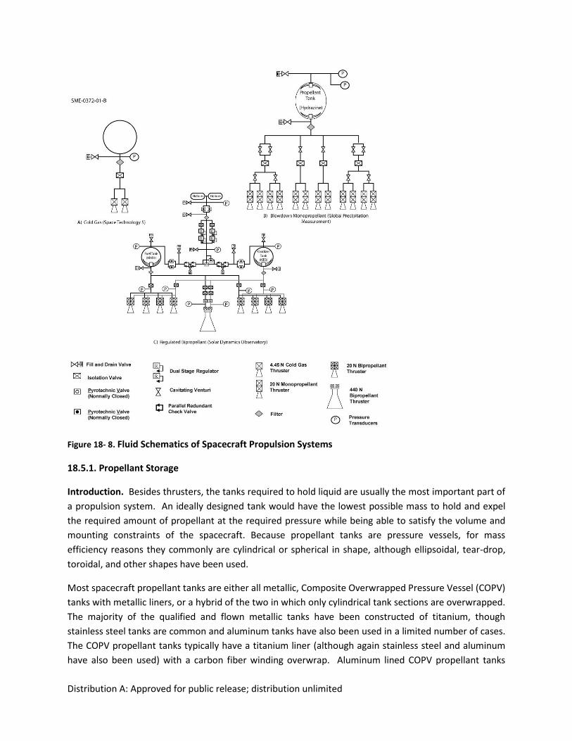
This section will cover more detailed aspects of spacecraft liquid propulsion design. Figures 18-8 a-c
gives a system schematic of representative cold gas, monopropellant and hypergolic bipropellants
systems. One can see the simplicity of a typical cold gas thruster which consists only of a tank, a couple
of valves, a filter, a pressure transducer and a nozzle. In what follows we will focus on options for
propellant storage and manifolding, pressurization systems, and other miscellaneous elements.
Distribution A: Approved for public release; distribution unlimited
Figure 18- 8. Fluid Schematics of Spacecraft Propulsion Systems
18.5.1. Propellant Storage
Introduction. Besides thrusters, the tanks required to hold liquid are usually the most important part of
a propulsion system. An ideally designed tank would have the lowest possible mass to hold and expel
the required amount of propellant at the required pressure while being able to satisfy the volume and
mounting constraints of the spacecraft. Because propellant tanks are pressure vessels, for mass
efficiency reasons they commonly are cylindrical or spherical in shape, although ellipsoidal, tear-drop,
toroidal, and other shapes have been used.
Most spacecraft propellant tanks are either all metallic, Composite Overwrapped Pressure Vessel (COPV)
tanks with metallic liners, or a hybrid of the two in which only cylindrical tank sections are overwrapped.
The majority of the qualified and flown metallic tanks have been constructed of titanium, though
stainless steel tanks are common and aluminum tanks have also been used in a limited number of cases.
The COPV propellant tanks typically have a titanium liner (although again stainless steel and aluminum
have also been used) with a carbon fiber winding overwrap. Aluminum lined COPV propellant tanks
Distribution A: Approved for public release; distribution unlimited
with aluminum Propellant Management Devices (see internal devices below) are being developed
specifically to demise upon reentry into the Earth’s atmosphere.
Integral to the choice of tanks and overall spacecraft design is the tank mounting provision. Tanks can
be mounted in a variety of ways, but the most common methods are boss end mounts, hemispherical
ring mounts, or circumferential skirts or tabs. Attention should be given to the most efficient way to
mount the tanks so that the combined tank mass and spacecraft support structure mass are minimized.
The change in tank size as it is pressurized can be significant. Usually tank mounting designs must make
provisions to allow for the expansion and contraction of the tank during pressure cycles. Flexures are
often used for this purpose.
Because of the amount of stored energy in both propellant and pressurant tanks, tanks are often the
most safety critical component on a spacecraft, and their design, testing, and implementation are
governed by several standards [AIAA, 1999; AIAA, 2006; Air Force Space Command, 2004].
Propellant tank internal devices. Devices internal to propellant tanks are used to ensure that only
propellant (and not pressurant gas) is expelled from the tanks. If significant pressurant gas is sent
through the thrusters, the system can lose its ability to maintain the required pressure, and thruster
performance and life can be compromised. Internal fluid management devices can also act as controls
on the location and movement of propellant (slosh) which can affect attitude control and act as an
energy dissipation mechanism for spin-stabilized spacecraft. For spin stabilized spacecraft or spacecraft
using launch vehicles with spin-stabilized stages, it is important to develop an early understanding of
how the on-board propellant configuration affects what is known as the nutation time constant. The
nutation time constant is the exponential constant, k, in an equation of the form: = ekt, where t is
time and represents the nutation angle, which is the angle between the momentum vector and the
coning angle. If grows faster than the vehicle control system can compensate, the system will be
headed in the wrong direction. Baffles, vanes, screens, bladders, diaphragms, and other internal devices
can be added to tanks to help control internal propellant motion, but testing is often required to prove
the effectiveness of a particular design. (See discussion of LRO’s nutation time constant issue in Sec.
14.6.1). Propellant slosh can also be a concern for 3-axis stabilized spacecraft. Slosh can cause pointing
disturbances, and has the potential of being magnified during thruster maneuvers if the periodic
thruster force is in resonance with the fluid motion.
To separate liquid propellant from pressurant gas, tanks use either physical barriers or devices that
depend on surface tension. Positive expulsion devices include diaphragm tanks (both metallic and
elastomeric), bladder tanks, bellows tanks, and piston tanks. Elastomeric diaphragms, which are
internally attached around the hemisphere of the tank, are perhaps the most common positive
expulsion devices because of their large cycle capability and minimal operational constraints.
Disadvantages of diaphragms tanks include their higher mass and material incompatibilities with
common oxidizers.
Surface tension devices internal to tanks, often referred to as Propellant Management Devices (PMD’s),
come in a variety of designs and levels of complexity. They are typically lighter than positive expulsion
Distribution A: Approved for public release; distribution unlimited
devices and are compatible with most fuels and oxidizers. PMD’s use surface tension forces to keep
fluids separate from gases as fluid is depleted from the tank. The design of PMD’s is a specialized field
and can be very complicated depending on mission requirements. PMD design relies on empirical and
analytical approaches. End-to-end testing of a PMD in zero gravity environments is almost always cost
prohibited. Detailed design depends on the detailed mission profile.
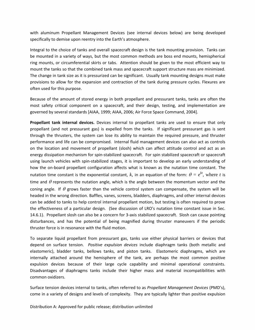
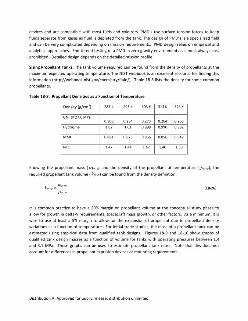
Sizing Propellant Tanks. The tank volume required can be found from the density of propellants at the
maximum expected operating temperature. The NIST webbook is an excellent resource for finding this
information (http://webbook.nist.gov/chemistry/fluid/). Table 18-8 lists the density for some common
propellants.
Table 18-8. Propellant Densities as a Function of Temperature
Density (g/cm3) 283 K 293 K 303 K 313 K 323 K
GN2 @ 27.6 MPa 0.300 0.284 0.273 0.264 0.255
Hydrazine 1.02 1.01 0.999 0.990 0.982
MMH 0.884 0.875 0.866 0.856 0.847
NTO 1.47 1.44 1.42 1.40 1.38
Knowing the propellant mass (
mprop) and the density of the propellant at temperature (
prop), the
required propellant tank volume (
Vprop) can be found from the density definition:
Vprop mprop
prop
(18-26)
It is common practice to have a 20% margin on propellant volume at the conceptual study phase to
allow for growth in delta-V requirements, spacecraft mass growth, or other factors. As a minimum, it is
wise to use at least a 5% margin to allow for the expansion of propellant due to propellant density
variations as a function of temperature. For initial trade studies, the mass of a propellant tank can be
estimated using empirical data from qualified tank designs. Figures 18-9 and 18-10 show graphs of
qualified tank design masses as a function of volume for tanks with operating pressures between 1.4
and 3.1 MPa. These graphs can be used to estimate propellant tank mass. Note that this does not
account for differences in propellant expulsion devices or mounting requirements.
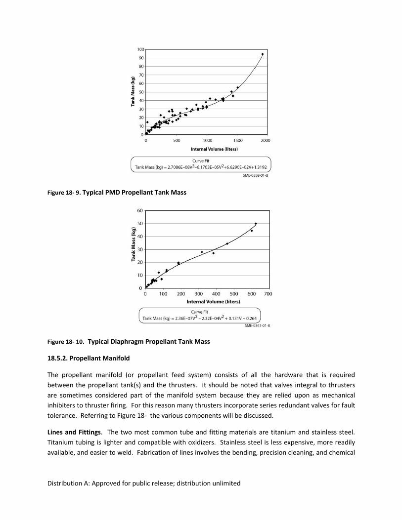
Distribution A: Approved for public release; distribution unlimited
Figure 18- 9. Typical PMD Propellant Tank Mass
Figure 18- 10. Typical Diaphragm Propellant Tank Mass
18.5.2. Propellant Manifold
The propellant manifold (or propellant feed system) consists of all the hardware that is required
between the propellant tank(s) and the thrusters. It should be noted that valves integral to thrusters
are sometimes considered part of the manifold system because they are relied upon as mechanical
inhibiters to thruster firing. For this reason many thrusters incorporate series redundant valves for fault
tolerance. Referring to Figure 18- the various components will be discussed.
Lines and Fittings. The two most common tube and fitting materials are titanium and stainless steel.
Titanium tubing is lighter and compatible with oxidizers. Stainless steel is less expensive, more readily
available, and easier to weld. Fabrication of lines involves the bending, precision cleaning, and chemical
Distribution A: Approved for public release; distribution unlimited
passivation of the lines. Integration of manifolds and components is performed in clean rooms to
prevent any internal contamination of the propulsion systems.
Isolation Valves. Isolation valves (or latch valves) are valves that can be commanded to an open or
closed position and remain in that position without continuous power. They serve several functions like
providing a required mechanical inhibit between the tank and the thruster outlet, isolating groups or
banks of thrusters in the event of systems failures; and isolating individual tanks in a multi-tank system
in order to control spacecraft mass properties.
Pyro Valves. Pyro valves are pyrotechnically actuated, one-time-use valves. They can be either
normally open (allowing flow until fired closed) or normally closed (preventing flow until fired open).
They can serve the same function as isolation valves with the exception that they can only be operated
once. The advantages they have over isolation valves include lower leak rates, smaller steady state
pressure drop, and smaller mass. Pyro valves are often used to isolate components for safety and
reliability concerns during the ground operations and launch phase or to isolate system components
after they have completed their function during the mission. System implementation of pyro valves
must include consideration of shock induced from activation.
Filters. The standard practice is to have propellant filters immediately downstream of propellant tanks
and any fill and drain valve servicing the tank, since the majority of particulates are likely to come from
the tank or fuel itself. The size of the filter is dependent on the amount of propellant required to pass
through the filter, the size of particulate filtration, and the allowable steady state pressure drop. In
addition to these stand-alone filters, other individual components such as isolation valves, regulators,
and thruster can have integral filters. The inclusion of filters in the system does not alleviate the need to
maintain strict cleanliness of the propulsion system. Particulate contamination can cause valve leakage
or flow blockage that can be mission ending. Chemical contamination can lead to catalyst bed poisoning
for monopropellant systems or degradation of material properties in high temperature coatings for
bipropellant systems.
Fill and Drain Valves. Some fill and drain valves are used solely for functional testing of components
once the systems is fully integrated. It is a standard requirement to have access to the fill and drain
valves once the spacecraft is in the launch vehicle fairing to allow for emergency offloading of
propellants.
Pressure Transducers. Pressure monitoring is required for propellant loading, pressurization, and
ground operations. Pressure monitoring on orbit is also used to evaluate the performance of the
system, to indicate possible failures, and to estimate parameters such as thrust, specific impulse, and
propellant mass consumption.
Flow Control Orifices. They are typically simple, machined fittings welded in line with the system
manifold. Flow control orifices are sometimes used to equalize any difference in pressure drops
between fuel and oxidizer feed lines so that the ideal thruster mixture ratio is maintained. Flow control
orifices are also used to minimize the transient flow in propulsion systems that can cause damaging
internal pressure spikes. Pressure spikes of this nature, called water-hammer events are common in the
Distribution A: Approved for public release; distribution unlimited
plumping and piping industry. Water-hammer events occur in liquid propulsion systems when valves
command to change state. (You may have experienced water hammer in your home plumbing system if
you suddenly turn a faucet on or off.)
18.5.3. Aspects of Pressurization Systems
Blow-Down Systems. A blow-down system is one in which an initial gas volume (or ullage) in a
propellant tank system is pressurized to a beginning-of-life pressure and then allow to expand and
decrease in pressure as propellant is consumed. This simple pressurization scheme can save on the cost
and complexity of a regulated pressurization system. To use this type of system the mission must allow
for the required tank volume and accommodate decreasing thrust levels as the mission proceeds Blow-
down systems are more common on cold gas and monopropellant systems since monopropellant
thrusters are typically qualified over a wide range of thruster inlet operating pressures (5.5 – 2.4 MPa).
Bipropellant systems often have a limitation on the allowable inlet pressure range because of the need
to have an acceptable fuel to oxidizer mixture ratio. Because of this, the blow-down pressure range for
bipropellants is limited. It is common to have bipropellant systems start off in a pressure regulated
mode and then transition to a blow-down mode once the ullage in the propellant tank is sufficient large
to allow for blow-down operation.
Regulated Systems. Pressure regulated systems are, as the term implies, systems in which the
propellant tank pressure is regulated at a fixed pressure over part or all of the mission life. The
advantages of pressure regulated system include; maximizing the propellant that can be carried in a
given tank volume, providing for consistent thrust and impulse levels, and providing consistent mixture
ratios for bipropellant systems. The pressurant gas, most often He or N2, is stored in high pressure tanks
(typically at 13.8 to 41.4 MPa) and regulated to the operational pressure of the propellant tanks and/or
thrusters. Regulation is performed by a mechanical regulator or, in some cases, a series of high-pressure
valves commanded open and closed by a pressure feedback control loop.
Pressurant Mass Determination. To obtain a first order estimate the mass of pressurant gas and the
size and mass of the high pressure tank you can work backwards from the end-of-life pressure required
and total propellant tank volume. (For a detailed determination of pressurant gas mass you must
consider the effects of the pressurant gas dissolving into the propellant, which is a function of pressure,
temperature, and the type of fluids being used.) For a pressure regulated system, the following steps
can be taken as a first approximation.
1. Estimate a maximum beginning of life operating pressure and temperature of the high pressure
tank. This would be the operational design requirements for the pressurant tank. Choose 27.6
MPa at 323 K as a starting point if you have no other inputs.
2. Determine the density of the pressurant gas at this state using a lookup table like Table 18-9 or
http://webbook.nist.gov/chemistry/fluid
Table 18-9. Pressurant Gas Density as a Function of Temperature and Pressure
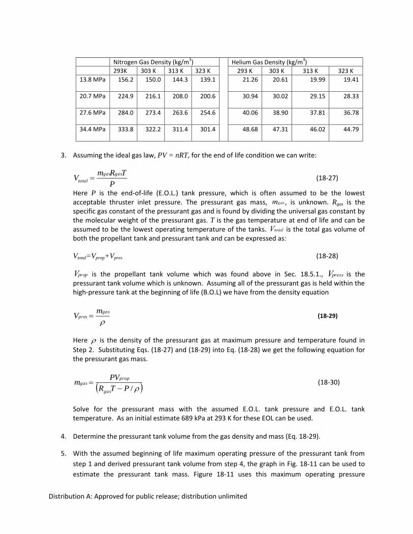
Distribution A: Approved for public release; distribution unlimited
Nitrogen Gas Density (kg/m
3) Helium Gas Density (kg/m
3)
293K 303 K 313 K 323 K 293 K 303 K 313 K 323 K
13.8 MPa 156.2 150.0 144.3 139.1 21.26 20.61 19.99 19.41
20.7 MPa 224.9 216.1 208.0 200.6 30.94 30.02 29.15 28.33
27.6 MPa 284.0 273.4 263.6 254.6 40.06 38.90 37.81 36.78
34.4 MPa 333.8 322.2 311.4 301.4 48.68 47.31 46.02 44.79
3. Assuming the ideal gas law, PV = nRT, for the end of life condition we can write:
P
TRmV
gasgas
total
(18-27)
Here P is the end-of-life (E.O.L.) tank pressure, which is often assumed to be the lowest acceptable thruster inlet pressure. The pressurant gas mass,
mgas, is unknown. Rgas is the specific gas constant of the pressurant gas and is found by dividing the universal gas constant by the molecular weight of the pressurant gas. T is the gas temperature at end of life and can be assumed to be the lowest operating temperature of the tanks.
Vtotal is the total gas volume of both the propellant tank and pressurant tank and can be expressed as:
Vtotal=Vprop+Vpres
(18-28)
Vprop is the propellant tank volume which was found above in Sec. 18.5.1.,
Vpress is the pressurant tank volume which is unknown. Assuming all of the pressurant gas is held within the high-pressure tank at the beginning of life (B.O.L) we have from the density equation
gaspres
mV
(18-29)
Here
is the density of the pressurant gas at maximum pressure and temperature found in
Step 2. Substituting Eqs. (18-27) and (18-29) into Eq. (18-28) we get the following equation for the pressurant gas mass.
/PTR
PVm
gas
propgas
(18-30)
Solve for the pressurant mass with the assumed E.O.L. tank pressure and E.O.L. tank temperature. As an initial estimate 689 kPa at 293 K for these EOL can be used.
4. Determine the pressurant tank volume from the gas density and mass (Eq. 18-29).
5. With the assumed beginning of life maximum operating pressure of the pressurant tank from
step 1 and derived pressurant tank volume from step 4, the graph in Fig. 18-11 can be used to
estimate the pressurant tank mass. Figure 18-11 uses this maximum operating pressure
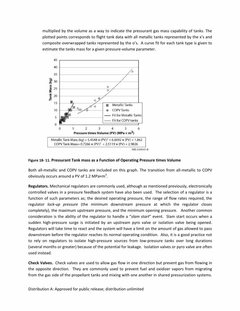
Distribution A: Approved for public release; distribution unlimited
multiplied by the volume as a way to indicate the pressurant gas mass capability of tanks. The
plotted points corresponds to flight tank data with all metallic tanks represented by the x’s and
composite overwrapped tanks represented by the o’s. A curve fit for each tank type is given to
estimate the tanks mass for a given pressure-volume parameter.
Figure 18- 11. Pressurant Tank mass as a Function of Operating Pressure times Volume
Both all-metallic and COPV tanks are included on this graph. The transition from all-metallic to COPV
obviously occurs around a PV of 1.2 MPa×m3.
Regulators. Mechanical regulators are commonly used, although as mentioned previously, electronically
controlled valves in a pressure feedback system have also been used. The selection of a regulator is a
function of such parameters as; the desired operating pressure, the range of flow rates required, the
regulator lock-up pressure (the minimum downstream pressure at which the regulator closes
completely), the maximum upstream pressure, and the minimum opening pressure. Another common
consideration is the ability of the regulator to handle a “slam start” event. Slam start occurs when a
sudden high-pressure surge is initiated by an upstream pyro valve or isolation valve being opened.
Regulators will take time to react and the system will have a limit on the amount of gas allowed to pass
downstream before the regulator reaches its normal operating condition. Also, it is a good practice not
to rely on regulators to isolate high-pressure sources from low-pressure tanks over long durations
(several months or greater) because of the potential for leakage. Isolation valves or pyro valve are often
used instead.
Check Valves. Check valves are used to allow gas flow in one direction but prevent gas from flowing in
the opposite direction. They are commonly used to prevent fuel and oxidizer vapors from migrating
from the gas side of the propellant tanks and mixing with one another in shared pressurization systems.
Distribution A: Approved for public release; distribution unlimited
Most bipropellants pressurize both fuel and oxidizer from a common regulated gas source in order to
have a reliable mixture ratio at the thrusters. If fuel and oxidizer vapor mix, there is a strong potential
for combustion which will cause catastrophic system failure.
18.5.4. Other System Considerations
Thermal Integration. Although temperature limits can vary slightly, typical hydrazine and non-cryogenic
bipropellants have temperatures ranging from 281 to 323 K. Many spacecraft configurations will
require that part or all of the propellant lines be wrapped with heaters to keep the propellant above a
minimum temperature. Individual flow components may have heaters placed directly on them or on
mounting brackets or plates. These heaters are typically etched foil elements enclosed on both sides by
Kapton film. Propellant tanks are typically covered with heaters attached to the outside of the tanks.
The poor thermal conductivity of titanium, stainless steel, and carbon windings drives the thermal
design such that relatively low power heaters cover a large portion of the components. Often aluminum
or even copper tape is used to distribute the heat from the heaters to the rest of the components. In
most situations the propellant lines, components, and tanks have individual blankets. These heaters,
tape, wiring and blankets can add significant mass.
Hydrazine thrusters typically require preheating of the catalyst bed prior to operation of the thruster.
Catalyst bed heaters are usually heated for a predetermined time prior to thruster operation instead of
relying on temperature monitoring. This power is usually book kept under the thruster’s operating
power instead of thermal system power.
Another thermal concern is the temperature drop due to pressurant gas expansion as propellant is
consumed. This is primarily a concern for long and/or high thrust burns in which the pressurant gas is
expanded at a rate that does not allow for relative thermal equilibrium between the tank and gas. It is
possible for the temperature in the pressurant tanks to decrease dramatically (for example a change of
over 50 K may be possible). To accommodate large burns you can start with a high initial gas
temperature before the start of the burn or you can heat the pressurant gas heated through a heat
exchanger before it reaches critical components.
Electrical Interfaces. Electronics are required to operate propulsion systems. Drive electronics for
propulsion valves (thruster valves, isolation valves, and pyro valves) supply the appropriate power to
actuate valves and account for effects such as the back EMF (Electro-Magnetic Field) seen with
solenoids. Valve drive electronics are often part of the attitude control subsystem because they must
work in union with the rest of the spacecraft control system. Sometimes pyro valve drivers are placed
on a separate pyro valve bus with other pyrotechnic components. Power to the propulsion survival
heaters often comes directly from the spacecraft power supply subsystem. Power for catalyst bed
heaters and pressure transducers may also come directly from the power subsystem or from an attitude
control box. Propulsion telemetry, which is primarily pressure, temperature, and valve position readings,
is sometimes handled directly by the spacecraft command and data handling subsystem.
18.6 Electric Propulsion
Distribution A: Approved for public release; distribution unlimited
William Hargus, Air Force Research Laboratory, Edwards AFB, CA
Electric propulsion traces its roots to Robert Goddard and others who independently determined that, unlike chemical propulsion, which is limited to intrinsic molecular bond energy, electric propulsion has the capability to increase specific impulse to values of 20,000 s or more [Jahn, 1968; Goddard and Penray, 1970; Choueriri, 2004]. Despite this early recognition of the potential benefits of electric propulsion, routine electric propulsion flight did not occur until the early 1990s. Although confined to low thrust applications due to limited onboard power generation and storage, electric propulsion is presently one of the more dynamic and inventive propulsion fields. 18.6.1. Classification by Acceleration Mechanism. Although there are a multitude of thruster concepts, electric propulsion may be divided into three general classes by the mechanism by which the propellant is accelerated [Jahn, 1968]. Electrothermal. In electrothermal electric propulsion, propellants are electrically heated and then
expanded through a nozzle. There are several energy deposition methods by which electrothermal
acceleration of propellants may be realized. These vary from relatively simple resistive heaters
(resistojets) and slightly more complex electrical arc heaters (arcjets), both of which accelerate their
heated propellant through a supersonic converging-diverging nozzle [Jahn, 1968], to more exotic laser
ablative thrusters, which have demonstrated that a nozzle is not necessary due to the two dimensional
isentropic expansion of the superheated ablation products from a surface [Phipps, 2006].
For electrothermal thrusters, the rocket equation (18-13 and 18-18) holds and light propellants will yield
the highest specific impulse. The use of propellants containing carbon and oxygen is generally avoided
due to carbon deposits shorting across electrodes and oxidation of refractory metal nozzles. However,
various electrodeless thruster concepts utilizing inductively coupled, or microwave resonance cavity,
plasmas have been developed in the laboratory to overcome this limitation [Hruby, 1997; Balaam, 1995;
Sullivan 2004].
Electrostatic. In electrostatic propulsion, electric fields are used to accelerate charged particles. The force acting on a charged particle in the presence of electric and magnetic fields is described by the Lorentz equation [Jahn, 1968; Wangsness, 1986].
)( BvEqF
(18-31)
where is the force on a charged particle of charge q and velocity produced by electric field and
magnetic field . For electrostatic electric propulsion, where there is no magnetic field or it does not
contribute substantially to the propellant acceleration, Eq. (18-31) reduces to .
An interesting system level issue for electrostatic electric propulsion is that heavy propellants are
preferred to light propellants. This preference stems from limited spacecraft electrical power. Using the
definition of Isp and defining the thruster efficiency as the quotient of the output directed kinetic
Distribution A: Approved for public release; distribution unlimited
energy flux ( spoe ITgVm2
1
2
1 2 ) and the input electrical power Pelec Eq. (18-32) illustrates the limiting
relationship between Pelec, T, and Isp [Jahn, 1968].
spo
elec
Ig
PT
2
(18-32)
where go (9.80665 m/s) is the Earth's gravitational constant, and Isp is the thruster's specific impulse.
Since electrical potentials of several hundred volts are required to accelerate ion beams, light ions
produce very high specific impulses, but correspondingly low thrust levels at constant thruster power.
High mass ions have long been used to increase thrust levels but consequently the Isp is lowered. This is
strongly preferred in Earth orbit where customer demand often dictates shorter orbit transfer times. For
interplanetary missions, high specific impulse may alternatively be the mission enabler.
The original propellants of interest for electrostatic thrusters during early development efforts in the
1960s and 1970s were cesium and mercury, but owing to their toxicity, modern thrusters generally use
xenon, although krypton and bismuth have received recent attention [Jahn, 1968; Goebel, 2008].
Electrostatic thrusters must also neutralize the accelerated ion beam to ensure the spacecraft is not
charged negative by the emitted positive ion beam. Due to charge separation during acceleration by
electric fields, neutralization of the ion beam is required of all electrostatic thrusters. The use of
dedicated neutralizers, particularly hollow cathode electron sources, generally requires very high
propellant purity (less than 10 ppm oxygen or water) in order to avoid oxidation, and subsequent failure,
of the sensitive, easily poisoned electron sources.
Electrostatic thrusters may be subdivided into two categories. The first includes gridded and Hall effect
thrusters. Gridded thrusters (Isp = 1,500-10,000 s), often referred to as ion engines or Kaufmann
thrusters, and Hall effect thrusters (Isp = 1,000-3,000 s) both produce a plasma and then accelerate the
positive ions which are subsequently externally neutralized. The primary difference between the two
types is that the gridded ion engines produce their electric field between two, or more, very precisely
aligned perforated screens, while the Hall effect thrusters magnetize the electrons in order to produce a
similar, but less focused, potential difference. A more subtle difference is that ion engines produce and
confine their ions non-neutrally, while the Hall effect thrusters retain a net neutral plasma during
propellant production and acceleration. Ion thrusters are therefore limited in their specific thrust due to
their need to contain substantial charge densities. The second subcategory of electrostatic thruster is
the electrospray [Zeimer, 2009]. Here, ions, or in some cases charged clusters or droplets, are
electrostatically extracted from an electrically conductive liquid and accelerated. Specific impulses
ranging from 100 s to over 20,000 s have been demonstrated with liquids including doped glycerin,
liquid metals, and various ionic liquids (molten salts). It is possible to operate these devices in a bipolar
mode where the ion accelerator alternatively extracts positive and then negative ions thus eliminating
the need for a dedicated neutralizer. The primary technical barrier to more widespread application of
this technology has been the difficulty in scaling from microscopic single emitters to large parallelized
ion extraction arrays.
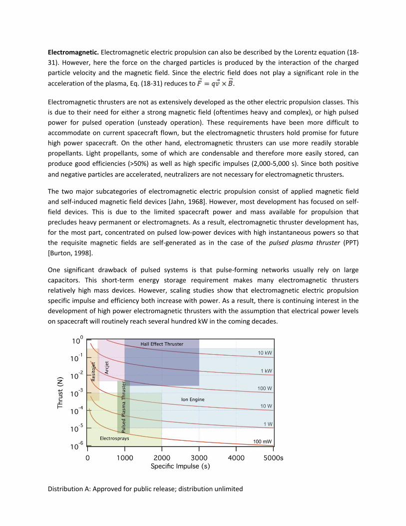
Distribution A: Approved for public release; distribution unlimited
Electromagnetic. Electromagnetic electric propulsion can also be described by the Lorentz equation (18-
31). However, here the force on the charged particles is produced by the interaction of the charged
particle velocity and the magnetic field. Since the electric field does not play a significant role in the
acceleration of the plasma, Eq. (18-31) reduces to .
Electromagnetic thrusters are not as extensively developed as the other electric propulsion classes. This
is due to their need for either a strong magnetic field (oftentimes heavy and complex), or high pulsed
power for pulsed operation (unsteady operation). These requirements have been more difficult to
accommodate on current spacecraft flown, but the electromagnetic thrusters hold promise for future
high power spacecraft. On the other hand, electromagnetic thrusters can use more readily storable
propellants. Light propellants, some of which are condensable and therefore more easily stored, can
produce good efficiencies (>50%) as well as high specific impulses (2,000-5,000 s). Since both positive
and negative particles are accelerated, neutralizers are not necessary for electromagnetic thrusters.
The two major subcategories of electromagnetic electric propulsion consist of applied magnetic field
and self-induced magnetic field devices [Jahn, 1968]. However, most development has focused on self-
field devices. This is due to the limited spacecraft power and mass available for propulsion that
precludes heavy permanent or electromagnets. As a result, electromagnetic thruster development has,
for the most part, concentrated on pulsed low-power devices with high instantaneous powers so that
the requisite magnetic fields are self-generated as in the case of the pulsed plasma thruster (PPT)
[Burton, 1998].
One significant drawback of pulsed systems is that pulse-forming networks usually rely on large
capacitors. This short-term energy storage requirement makes many electromagnetic thrusters
relatively high mass devices. However, scaling studies show that electromagnetic electric propulsion
specific impulse and efficiency both increase with power. As a result, there is continuing interest in the
development of high power electromagnetic thrusters with the assumption that electrical power levels
on spacecraft will routinely reach several hundred kW in the coming decades.
Distribution A: Approved for public release; distribution unlimited
Figure 18- 12. Thruster operational envelopes with respect to thrust and specific impulse. Constant
power lines assuming 100% conversion efficiency are included to illustrate electric propulsion thruster
electrical power requirements.
18.6.2. Thruster Selection and Critical Subsystems. Selection of an appropriate electric propulsion
thruster for any particular mission must take into account a number of important engineering
constraints, including available power, mass, and volume. Furthermore, the use of electric propulsion at
present constrains the mission planner to low thrust trajectories. Once all these constraints are
identified and understood, a chart such as the one in Fig. 18-12 can be used to select an appropriate
thruster.
It is important to note that there is considerable variability in the operating parameters (namely power)
of nearly all electric propulsion thrusters. Thruster performance is usually quoted for an optimal so
called nominal condition. Usually this condition exhibits peak electrical conversion efficiency, maximum
lifetime, most stable operation, or some such combination. However, many steady state electric
thrusters maybe operated between 25% and 200% of their nominal power. With special regard to
electrostatic thrusters, the specific impulse can also be raised and lowered somewhat arbitrarily by
varying the applied acceleration potential. It must be stressed that operation at off nominal operating
parameters will likely be detrimental to the thruster electrical conversion efficiency in the short term,
and lifetime in the long term. The loss of efficiency can generally be discerned from available test data,
but the effect of off-nominal operation on lifetime is difficult to predict without ground test verification.
Electric propulsion systems are themselves composed of a number of subsystems. These include the
thruster itself, power processing, propellant distribution, tankage, and thruster mounts (sometimes
including gimbals). The most complex electric propulsion subsystem is nearly always the power
processing unit (PPU) subsystem. The PPU regulates the spacecraft bus power and converts it into
thruster required electrical potentials and currents. PPU’s vary from relatively simple current sources for
resistojet heating elements, several independent high voltage DC power supplies for ion engines and
Hall thrusters, and extend even to high current, negative impedance arcjet power supplies coupled with
pulsed arc initiation start circuits. The PPU subsystem also generally includes valve drivers for the
propellant management subsystem and the digital control interface to spacecraft-based command and
control.
PPU subsystems required to produce and regulate suitable electrical power for electric thrusters have
finite efficiencies that strongly depend on the spacecraft bus voltage since higher bus voltages tend to
increase processing efficiency. PPUs can be single set point, multiple set point, or continuously variable
over some range. The addition of flexible power operation may decrease efficiencies from above 95% to
below 90%. The resulting waste heat must be rejected without adversely affecting the operation of the
host spacecraft. Thermal design of electric propulsion systems must be accounted for early in spacecraft
design. As an example, consider the difficulties involved in safely rejecting 1 kW of heat from a 10 kW,
90% efficient PPU subsystem mounted within a spacecraft.
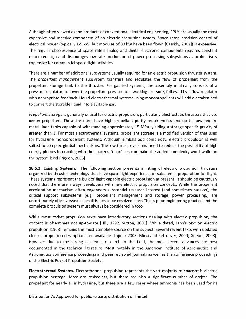
Distribution A: Approved for public release; distribution unlimited
Although often viewed as the products of conventional electrical engineering, PPUs are usually the most
expensive and massive component of an electric propulsion system. Space rated precision control of
electrical power (typically 1-5 kW, but modules of 30 kW have been flown [Cassidy, 2002]) is expensive.
The regular obsolescence of space rated analog and digital electronic components requires constant
minor redesign and discourages low rate production of power processing subsystems as prohibitively
expensive for commercial spaceflight activities.
There are a number of additional subsystems usually required for an electric propulsion thruster system.
The propellant management subsystem transfers and regulates the flow of propellant from the
propellant storage tank to the thruster. For gas fed systems, the assembly minimally consists of a
pressure regulator, to lower the propellant pressure to a working pressure, followed by a flow regulator
with appropriate feedback. Liquid electrothermal systems using monopropellants will add a catalyst bed
to convert the storable liquid into a suitable gas.
Propellant storage is generally critical for electric propulsion, particularly electrostatic thrusters that use
xenon propellant. These thrusters have high propellant purity requirements and up to now require
metal lined tanks capable of withstanding approximately 15 MPa, yielding a storage specific gravity of
greater than 1. For most electrothermal systems, propellant storage is a modified version of that used
for hydrazine monopropellant systems. Although gimbals add complexity, electric propulsion is well
suited to complex gimbal mechanisms. The low thrust levels and need to reduce the possibility of high
energy plumes interacting with the spacecraft surfaces can make the added complexity worthwhile on
the system level [Pigeon, 2006].
18.6.3. Existing Systems. The following section presents a listing of electric propulsion thrusters organized by thruster technology that have spaceflight experience, or substantial preparation for flight. These systems represent the bulk of flight capable electric propulsion at present. It should be cautiously noted that there are always developers with new electric propulsion concepts. While the propellant acceleration mechanism often engenders substantial research interest (and sometimes passion), the critical support subsystems (e.g., propellant management and storage, power processing.) are unfortunately often viewed as small issues to be resolved later. This is poor engineering practice and the complete propulsion system must always be considered in toto. While most rocket propulsion texts have introductory sections dealing with electric propulsion, the
content is oftentimes not up-to-date [Hill, 1992; Sutton, 2001]. While dated, Jahn's text on electric
propulsion [1968] remains the most complete source on the subject. Several recent texts with updated
electric propulsion descriptions are available [Tajmar 2003; Micci and Ketsdever, 2000; Goebel, 2008].
However due to the strong academic research in the field, the most recent advances are best
documented in the technical literature. Most notably in the American Institute of Aeronautics and
Astronautics conference proceedings and peer reviewed journals as well as the conference proceedings
of the Electric Rocket Propulsion Society.
Electrothermal Systems. Electrothermal propulsion represents the vast majority of spacecraft electric
propulsion heritage. Most are resistojets, but there are also a significant number of arcjets. The
propellant for nearly all is hydrazine, but there are a few cases where ammonia has been used for its
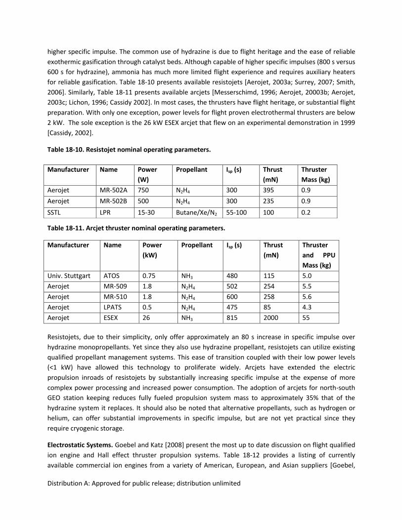
Distribution A: Approved for public release; distribution unlimited
higher specific impulse. The common use of hydrazine is due to flight heritage and the ease of reliable
exothermic gasification through catalyst beds. Although capable of higher specific impulses (800 s versus
600 s for hydrazine), ammonia has much more limited flight experience and requires auxiliary heaters
for reliable gasification. Table 18-10 presents available resistojets [Aerojet, 2003a; Surrey, 2007; Smith,
2006]. Similarly, Table 18-11 presents available arcjets [Messerschimd, 1996; Aerojet, 20003b; Aerojet,
2003c; Lichon, 1996; Cassidy 2002]. In most cases, the thrusters have flight heritage, or substantial flight
preparation. With only one exception, power levels for flight proven electrothermal thrusters are below
2 kW. The sole exception is the 26 kW ESEX arcjet that flew on an experimental demonstration in 1999
[Cassidy, 2002].
Table 18-10. Resistojet nominal operating parameters.
Table 18-11. Arcjet thruster nominal operating parameters.
Manufacturer Name Power
(kW)
Propellant Isp (s) Thrust
(mN)
Thruster
and PPU
Mass (kg)
Univ. Stuttgart ATOS 0.75 NH3 480 115 5.0
Aerojet MR-509 1.8 N2H4 502 254 5.5
Aerojet MR-510 1.8 N2H4 600 258 5.6
Aerojet LPATS 0.5 N2H4 475 85 4.3
Aerojet ESEX 26 NH3 815 2000 55
Resistojets, due to their simplicity, only offer approximately an 80 s increase in specific impulse over
hydrazine monopropellants. Yet since they also use hydrazine propellant, resistojets can utilize existing
qualified propellant management systems. This ease of transition coupled with their low power levels
(<1 kW) have allowed this technology to proliferate widely. Arcjets have extended the electric
propulsion inroads of resistojets by substantially increasing specific impulse at the expense of more
complex power processing and increased power consumption. The adoption of arcjets for north-south
GEO station keeping reduces fully fueled propulsion system mass to approximately 35% that of the
hydrazine system it replaces. It should also be noted that alternative propellants, such as hydrogen or
helium, can offer substantial improvements in specific impulse, but are not yet practical since they
require cryogenic storage.
Electrostatic Systems. Goebel and Katz [2008] present the most up to date discussion on flight qualified
ion engine and Hall effect thruster propulsion systems. Table 18-12 provides a listing of currently
available commercial ion engines from a variety of American, European, and Asian suppliers [Goebel,
Manufacturer Name Power
(W)
Propellant Isp (s) Thrust
(mN)
Thruster
Mass (kg)
Aerojet MR-502A 750 N2H4 300 395 0.9
Aerojet MR-502B 500 N2H4 300 235 0.9
SSTL LPR 15-30 Butane/Xe/N2 55-100 100 0.2
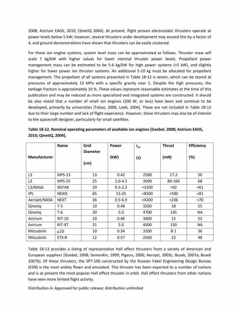
Distribution A: Approved for public release; distribution unlimited
2008; Astrium EADS, 2010; QinetiQ 2004]. At present, flight proven electrostatic thrusters operate at
power levels below 5 kW; however, several thrusters under development may exceed this by a factor of
4, and ground demonstrations have shown that thrusters can be easily clustered.
For these ion engine systems, system level mass can be approximated as follows. Thruster mass will
scale 7 kg/kW with higher values for lower nominal thruster power levels. Propellant power
management mass can be estimated to be 5-6 kg/kW for high power systems (>5 kW), and slightly
higher for lower power ion thruster systems. An additional 5-10 kg must be allocated for propellant
management. The propellant of all systems presented in Table 18-12 is xenon, which can be stored at
pressures of approximately 13 MPa with a specific gravity near 1. Despite the high pressures, the
tankage fraction is approximately 10 %. These values represent reasonable estimates at the time of this
publication and may be reduced as more specialized and integrated systems are constructed. It should
be also noted that a number of small ion engines (200 W, or less) have been and continue to be
developed, primarily by universities [Takao, 2006; Loeb, 2004]. These are not included in Table 18-12
due to their large number and lack of flight experience. However, these thrusters may also be of interest
to the spacecraft designer, particularly for small satellites.
Table 18-12. Nominal operating parameters of available ion engines [Goebel, 2008; Astrium EADS,
2010; QinetiQ, 2004].
Manufacturer
Name Grid
Diameter
(cm)
Power
(kW)
Isp
(s)
Thrust
(mN)
Efficiency
(%)
L3 XIPS-13 13 0.42 2500 17.2 50
L3 XIPS-25 25 2.0-4.3 3500 80-166 68
L3/NASA NSTAR 29 0.5-2.3 <3100 <92 <61
JPL NEXIS 65 15-25 <8500 <500 <81
Aerojet/NASA NEXT 36 0.5-6.9 <4200 <236 <70
Qinetiq T-5 10 0.48 3200 18 55
Qinetiq T-6 30 5.0 4700 145 NA
Astrium RIT-10 10 0.46 3400 15 52
Astrium RIT-XT 21 5.0 4500 150 NA
Mitsubishi 10 10 0.34 3100 8.1 36
Mitsubishi ETS-8 12 0.57 2500 22 48
Table 18-13 provides a listing of representative Hall effect thrusters from a variety of American and
European suppliers [Goebel, 2008; Semenkin, 1999; Pigeon, 2006; Aerojet, 2003c; Busek, 2007a; Busek
2007b]. Of these thrusters, the SPT-100 constructed by the Russian Fakel Engineering Design Bureau
(EDB) is the most widely flown and emulated. This thruster has been exported to a number of nations
and is at present the most popular Hall effect thruster in orbit. Hall effect thrusters from other nations
have seen more limited flight activity.
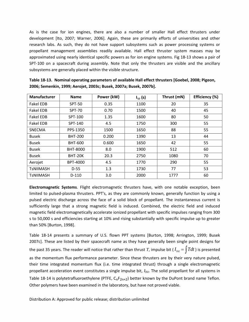
Distribution A: Approved for public release; distribution unlimited
As is the case for ion engines, there are also a number of smaller Hall effect thrusters under
development [Ito, 2007; Warner, 2006]. Again, these are primarily efforts of universities and other
research labs. As such, they do not have support subsystems such as power processing systems or
propellant management assemblies readily available. Hall effect thruster system masses may be
approximated using nearly identical specific powers as for ion engine systems. Fig 18-13 shows a pair of
SPT-100 on a spacecraft during assembly. Note that only the thrusters are visible and the ancillary
subsystems are generally placed within the visible structure.
Table 18-13. Nominal operating parameters of available Hall effect thrusters [Goebel, 2008; Pigeon,
2006; Semenkin, 1999; Aerojet, 2003c; Busek, 2007a; Busek, 2007b].
Manufacturer Name Power (kW) Isp (s) Thrust (mN) Efficiency (%)
Fakel EDB SPT-50 0.35 1100 20 35
Fakel EDB SPT-70 0.70 1500 40 45
Fakel EDB SPT-100 1.35 1600 80 50
Fakel EDB SPT-140 4.5 1750 300 55
SNECMA PPS-1350 1500 1650 88 55
Busek BHT-200 0.200 1390 13 44
Busek BHT-600 0.600 1650 42 55
Busek BHT-8000 8.0 1900 512 60
Busek BHT-20K 20.3 2750 1080 70
Aerojet BPT-4000 4.5 1770 290 55
TsNIIMASH D-55 1.3 1730 77 53
TsNIIMASH D-110 3.0 2000 1777 60
Electromagnetic Systems. Flight electromagnetic thrusters have, with one notable exception, been
limited to pulsed-plasma thrusters. PPT's, as they are commonly known, generally function by using a
pulsed electric discharge across the face of a solid block of propellant. The instantaneous current is
sufficiently large that a strong magnetic field is induced. Combined, the electric field and induced
magnetic field electromagnetically accelerate ionized propellant with specific impulses ranging from 300
s to 50,000 s and efficiencies starting at 10% and rising substantially with specific impulse up to greater
than 50% [Burton, 1998].
Table 18-14 presents a summary of U.S. flown PPT systems [Burton, 1998; Arrington, 1999; Busek
2007c]. These are listed by their spacecraft name as they have generally been single point designs for
the past 35 years. The reader will notice that rather than thrust T, impulse bit ( TdtIbit ) is presented
as the momentum flux performance parameter. Since these thrusters are by their very nature pulsed,
their time integrated momentum flux (i.e. time integrated thrust) through a single electromagnetic
propellant acceleration event constitutes a single impulse bit, Ibit. The solid propellant for all systems in
Table 18-14 is polytetrafluoroethylene (PTFE, CnF2n+2) better known by the DuPont brand name Teflon.
Other polymers have been examined in the laboratory, but have not proved viable.
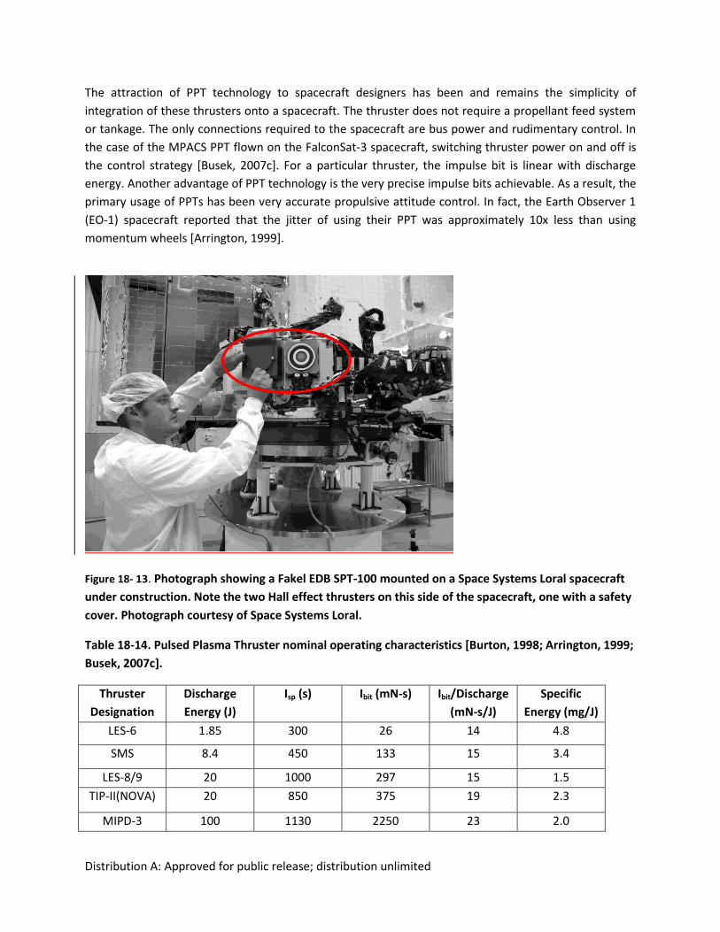
Distribution A: Approved for public release; distribution unlimited
The attraction of PPT technology to spacecraft designers has been and remains the simplicity of
integration of these thrusters onto a spacecraft. The thruster does not require a propellant feed system
or tankage. The only connections required to the spacecraft are bus power and rudimentary control. In
the case of the MPACS PPT flown on the FalconSat-3 spacecraft, switching thruster power on and off is
the control strategy [Busek, 2007c]. For a particular thruster, the impulse bit is linear with discharge
energy. Another advantage of PPT technology is the very precise impulse bits achievable. As a result, the
primary usage of PPTs has been very accurate propulsive attitude control. In fact, the Earth Observer 1
(EO-1) spacecraft reported that the jitter of using their PPT was approximately 10x less than using
momentum wheels [Arrington, 1999].
Figure 18- 13. Photograph showing a Fakel EDB SPT-100 mounted on a Space Systems Loral spacecraft
under construction. Note the two Hall effect thrusters on this side of the spacecraft, one with a safety
cover. Photograph courtesy of Space Systems Loral.
Table 18-14. Pulsed Plasma Thruster nominal operating characteristics [Burton, 1998; Arrington, 1999;
Busek, 2007c].
Thruster
Designation
Discharge
Energy (J)
Isp (s) Ibit (mN-s) Ibit/Discharge
(mN-s/J)
Specific
Energy (mg/J)
LES-6 1.85 300 26 14 4.8
SMS 8.4 450 133 15 3.4
LES-8/9 20 1000 297 15 1.5
TIP-II(NOVA) 20 850 375 19 2.3
MIPD-3 100 1130 2250 23 2.0
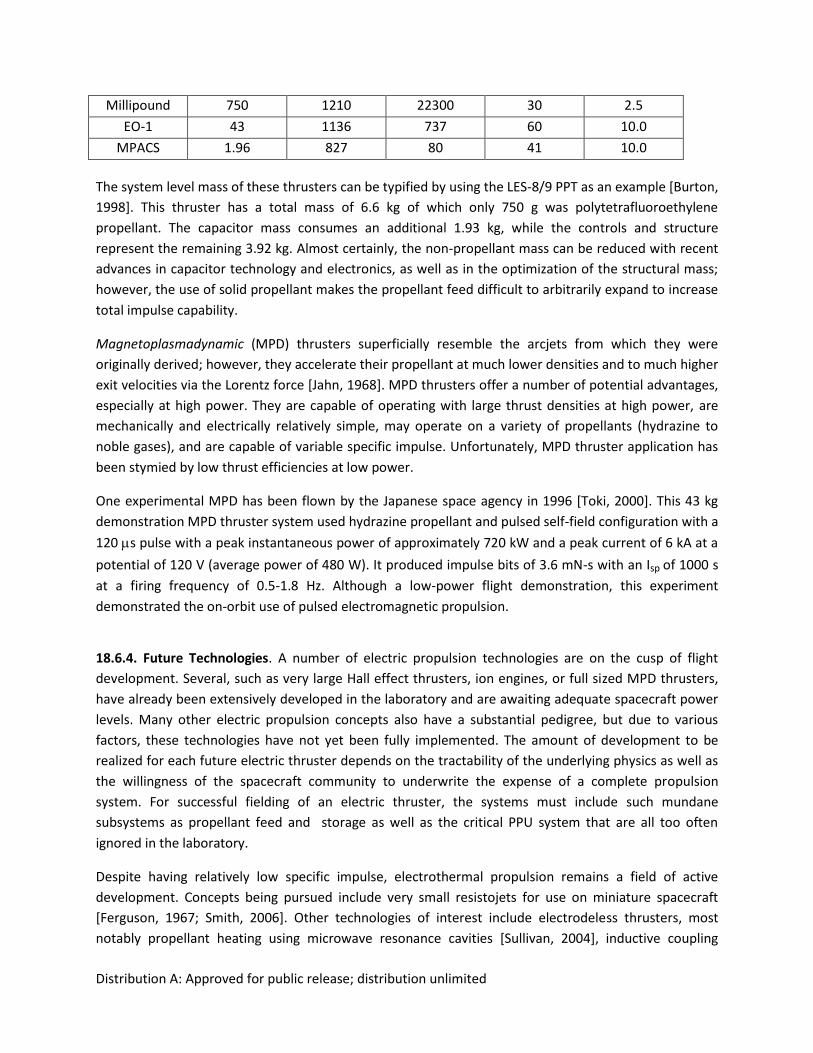
Distribution A: Approved for public release; distribution unlimited
Millipound 750 1210 22300 30 2.5
EO-1 43 1136 737 60 10.0
MPACS 1.96 827 80 41 10.0
The system level mass of these thrusters can be typified by using the LES-8/9 PPT as an example [Burton,
1998]. This thruster has a total mass of 6.6 kg of which only 750 g was polytetrafluoroethylene
propellant. The capacitor mass consumes an additional 1.93 kg, while the controls and structure
represent the remaining 3.92 kg. Almost certainly, the non-propellant mass can be reduced with recent
advances in capacitor technology and electronics, as well as in the optimization of the structural mass;
however, the use of solid propellant makes the propellant feed difficult to arbitrarily expand to increase
total impulse capability.
Magnetoplasmadynamic (MPD) thrusters superficially resemble the arcjets from which they were
originally derived; however, they accelerate their propellant at much lower densities and to much higher
exit velocities via the Lorentz force [Jahn, 1968]. MPD thrusters offer a number of potential advantages,
especially at high power. They are capable of operating with large thrust densities at high power, are
mechanically and electrically relatively simple, may operate on a variety of propellants (hydrazine to
noble gases), and are capable of variable specific impulse. Unfortunately, MPD thruster application has
been stymied by low thrust efficiencies at low power.
One experimental MPD has been flown by the Japanese space agency in 1996 [Toki, 2000]. This 43 kg
demonstration MPD thruster system used hydrazine propellant and pulsed self-field configuration with a
120 s pulse with a peak instantaneous power of approximately 720 kW and a peak current of 6 kA at a
potential of 120 V (average power of 480 W). It produced impulse bits of 3.6 mN-s with an Isp of 1000 s
at a firing frequency of 0.5-1.8 Hz. Although a low-power flight demonstration, this experiment
demonstrated the on-orbit use of pulsed electromagnetic propulsion.
18.6.4. Future Technologies. A number of electric propulsion technologies are on the cusp of flight
development. Several, such as very large Hall effect thrusters, ion engines, or full sized MPD thrusters,
have already been extensively developed in the laboratory and are awaiting adequate spacecraft power
levels. Many other electric propulsion concepts also have a substantial pedigree, but due to various
factors, these technologies have not yet been fully implemented. The amount of development to be
realized for each future electric thruster depends on the tractability of the underlying physics as well as
the willingness of the spacecraft community to underwrite the expense of a complete propulsion
system. For successful fielding of an electric thruster, the systems must include such mundane
subsystems as propellant feed and storage as well as the critical PPU system that are all too often
ignored in the laboratory.
Despite having relatively low specific impulse, electrothermal propulsion remains a field of active
development. Concepts being pursued include very small resistojets for use on miniature spacecraft
[Ferguson, 1967; Smith, 2006]. Other technologies of interest include electrodeless thrusters, most
notably propellant heating using microwave resonance cavities [Sullivan, 2004], inductive coupling
Distribution A: Approved for public release; distribution unlimited
[Gesto, 2006], or laser ablation [Phipps, 2004]. The goal of these new electrothermal thrusters is to be
able to use propellants with oxygen, and/or carbon that are more storable, exhibit higher performance,
and are less toxic than hydrazine. There is also some discussion of multimode propulsion where a single
propellant is used for both onboard chemical and electric propulsion systems, thereby providing
considerably increased mission flexibility.
In addition to the scaling up of electrostatic thrusters [Jacobson, 2003], several programs are
investigating boosting Hall effect thruster specific impulse above 3,000 s for interplanetary missions,
primarily to take advantage of commercial Hall effect thruster system-level investments [Vial, 2009;
Peterson, 2005; Hofer, 2006]. Hall effect thruster developers are also examining alternative propellants
such as krypton [Linnell, 2006], bismuth [Tverdokhlebov, 2002], and iodine [Dressler, 2000].
Probably the most exciting ongoing research in electrostatic thrusters is the development of massively
parallel arrays of electrosprays [Smith, 2009; Legge, 2007; Zeimer, 2009]. If the efficiencies
demonstrated for single emitters can be maintained over thousands, or millions, of microscopic
emitters, it may be possible to develop electrostatic thrusters of very large power levels with greater
than 80% electrical efficiency over wide ranges of specific impulse, using condensed phase propellant
storage. Progress in this technology lies not in improving on the physics of the propellant acceleration,
but in the engineering of the parallel arrays and requisite propellant distribution system.
High power electromagnetic thruster development has long focused on MPD thrusters, which scale best
for power levels above 100 kW. Metal propellants such as lithium have been proposed [Tikhonov, 1997],
but lifetimes are expensive to verify and spacecraft interactions with condensable metal propellants are
worrisome. Other devices such as pulsed inductive thrusters (PIT) [Mikellides, 2007], the field reversed
configurations (FRC) [Martin, 2005], the variable specific impulse magneto-plasma rocket (VASIMR)
[Chang-Diaz, 2000], and several other plasmoid accelerators [Choueriri, 2006; Poehlmann, 2007] are also
currently being investigated as potential high power thruster technologies (Sec. 18.7.3). These systems
scale well for very high power systems and are not limited by propellant selection.
18.7 Alternative Propulsion Systems for In-Space Use
Marc Young, Air Force Research Laboratory, Edwards AFB, CA
Research and development is very active in the space propulsion field in general: flight qualified
propulsion systems are continuously being improved; steady research is being conducted on alternative,
but not yet adopted, propulsion systems, and entirely new types of propulsion systems are being
investigated. It is useful to stay up-to-date on propulsion research because significant developments in
either space access or in-space propulsion systems may enable entirely new classes of space missions.
This section will summarize the current state of development of in-space propulsion systems as of 2010.
The state of development of emerging propulsion technologies is commonly measured relative to the
DOD or NASA Technology Readiness Level (TRL) defined in Chap. 11. This section will focus primarily on
the most fundamental characteristics of propulsion technologies with intermediate TRLs, 3 - 6.
Distribution A: Approved for public release; distribution unlimited
In-space propulsion systems are, in general, physically smaller than space access systems and are
applied to a much broader range of applications which leads to a much wider range of useful
technologies. A primary difference is the inclusion of electric propulsion systems which have significantly
higher specific impulses at significantly lower thrust levels. Development continues on the entire range
of systems and only a very brief review can be given here.
It is reasonable to assume that the current state-of-the-art for in-space propulsion systems will continue
to improve through improvements in available materials, wider operating ranges, increased lifetimes,
and new propellants. This section will instead focus on new ways of propelling moderately sized
spacecraft (m = 500 kg - 10,000 kg) and summarize leading candidates for both small spacecraft (m <
500 kg) propulsion systems and large spacecraft (m > 10,000 kg) propulsion systems.
18.7. 1 New Propulsion Systems for Moderately Sized Spacecraft
A variety of high performance chemical and electric propulsion systems for moderate-scale satellites
have been developed. Chemical propulsion systems with ever higher energy density are being
investigated. Existing moderate-scale electric propulsion systems provide a nearly complete set of
consistent high performance devices except, perhaps, at a specific impulse of around 1000 s where both
electrothermal and electrostatic/electromagnetic systems typically have unacceptably low efficiencies.
This section discusses several representative propulsion systems that operate significantly differently
than existing systems and may find use in niche applications.
Solar Thermal Propulsion. One potential method of achieving high thrust efficiency at specific impulses
around 1000 s is solar thermal propulsion [Henshall, 2006]. Solar thermal propulsion absorbs direct
solar energy with a heat exchanger. A propellant gas, typically hydrogen, flows over the heat exchanger
and is expelled out of a nozzle to produce thrust. The technology has been under development for
decades and may also find use in small satellite propulsion systems. Designs for solar thermal
propulsion typically yield specific impulses between 400 s (ammonia) and 1000 s (hydrogen) and operate
at heat exchanger temperatures of 2000 K to 3000 K. Long term hydrogen storage is still a problem that
requires addressing for many systems. Dual mode systems (both power and propulsion) using
significant thermal energy storage may bypass the need for photovoltaic cells and electrochemical
batteries entirely. The basic technology for solar thermal propulsion systems is proven and could be
employed in microsatellites in the near-term.
Solar Sail
Richard Van Allen, Microcosm, Hawthorne, CA
The concept of utilizing light pressure as a means of space propulsion is attributed to Konstantine Tsiolkovskii
[1921], 5 years before Robert Goddard launched the first liquid-fueled rocket. Tsander [1924] coined the term
“solar sailing” in the first technical publication on this topic. In that paper, Tsander calculated several
interplanetary trajectories for solar sail spacecraft and identified several useful configurations. It wasn’t until the
1950’s that additional papers were published *Wiley, 1951; Garwin, 1958+. Leap forward 20 years to the 1970’s
before the possibility of rendezvousing with Halley’s Comet triggered more analyses of solar sail applications
(Wright, 1974, 1976; Friedman, 1978).
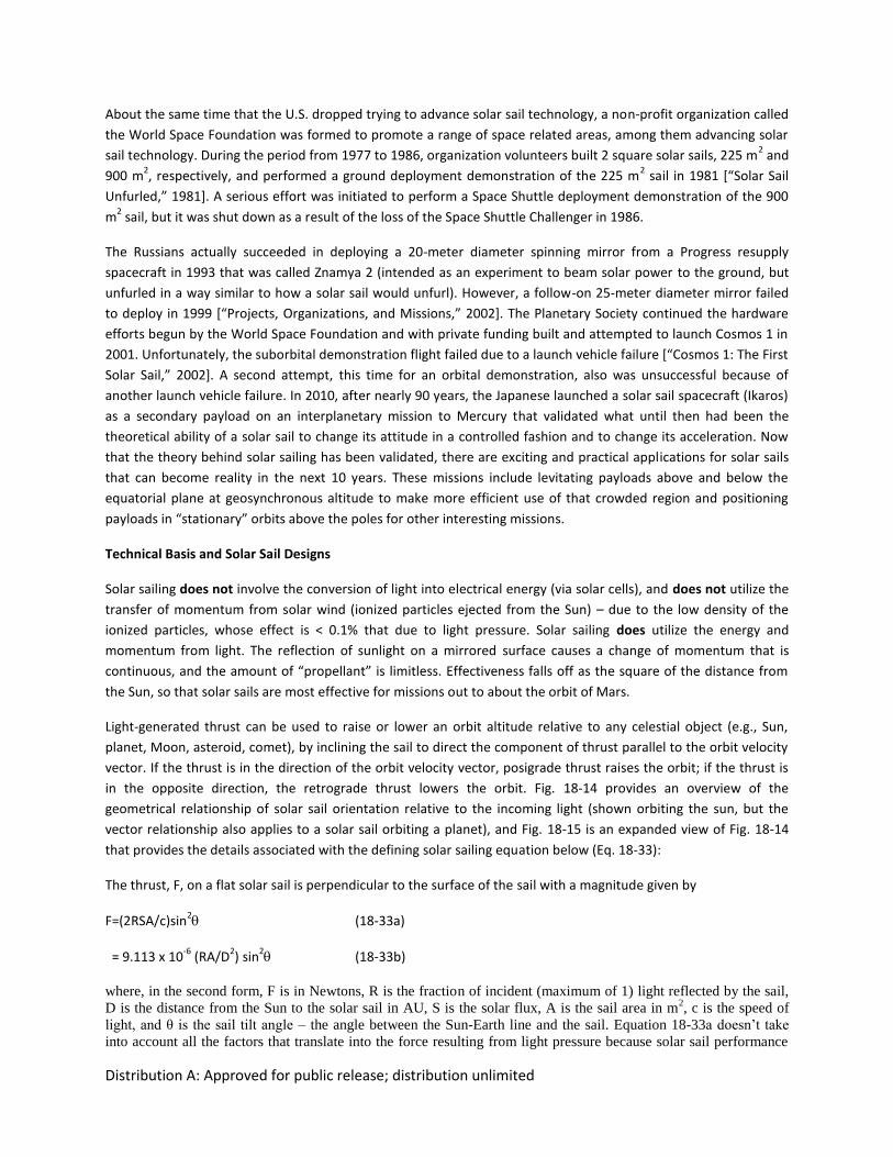
Distribution A: Approved for public release; distribution unlimited
About the same time that the U.S. dropped trying to advance solar sail technology, a non-profit organization called
the World Space Foundation was formed to promote a range of space related areas, among them advancing solar
sail technology. During the period from 1977 to 1986, organization volunteers built 2 square solar sails, 225 m2 and
900 m2, respectively, and performed a ground deployment demonstration of the 225 m
2 sail in 1981 *“Solar Sail
Unfurled,” 1981+. A serious effort was initiated to perform a Space Shuttle deployment demonstration of the 900
m2 sail, but it was shut down as a result of the loss of the Space Shuttle Challenger in 1986.
The Russians actually succeeded in deploying a 20-meter diameter spinning mirror from a Progress resupply
spacecraft in 1993 that was called Znamya 2 (intended as an experiment to beam solar power to the ground, but
unfurled in a way similar to how a solar sail would unfurl). However, a follow-on 25-meter diameter mirror failed
to deploy in 1999 *“Projects, Organizations, and Missions,” 2002+. The Planetary Society continued the hardware
efforts begun by the World Space Foundation and with private funding built and attempted to launch Cosmos 1 in
2001. Unfortunately, the suborbital demonstration flight failed due to a launch vehicle failure *“Cosmos 1: The First
Solar Sail,” 2002+. A second attempt, this time for an orbital demonstration, also was unsuccessful because of
another launch vehicle failure. In 2010, after nearly 90 years, the Japanese launched a solar sail spacecraft (Ikaros)
as a secondary payload on an interplanetary mission to Mercury that validated what until then had been the
theoretical ability of a solar sail to change its attitude in a controlled fashion and to change its acceleration. Now
that the theory behind solar sailing has been validated, there are exciting and practical applications for solar sails
that can become reality in the next 10 years. These missions include levitating payloads above and below the
equatorial plane at geosynchronous altitude to make more efficient use of that crowded region and positioning
payloads in “stationary” orbits above the poles for other interesting missions.
Technical Basis and Solar Sail Designs
Solar sailing does not involve the conversion of light into electrical energy (via solar cells), and does not utilize the
transfer of momentum from solar wind (ionized particles ejected from the Sun) – due to the low density of the
ionized particles, whose effect is < 0.1% that due to light pressure. Solar sailing does utilize the energy and
momentum from light. The reflection of sunlight on a mirrored surface causes a change of momentum that is
continuous, and the amount of “propellant” is limitless. Effectiveness falls off as the square of the distance from
the Sun, so that solar sails are most effective for missions out to about the orbit of Mars.
Light-generated thrust can be used to raise or lower an orbit altitude relative to any celestial object (e.g., Sun,
planet, Moon, asteroid, comet), by inclining the sail to direct the component of thrust parallel to the orbit velocity
vector. If the thrust is in the direction of the orbit velocity vector, posigrade thrust raises the orbit; if the thrust is
in the opposite direction, the retrograde thrust lowers the orbit. Fig. 18-14 provides an overview of the
geometrical relationship of solar sail orientation relative to the incoming light (shown orbiting the sun, but the
vector relationship also applies to a solar sail orbiting a planet), and Fig. 18-15 is an expanded view of Fig. 18-14
that provides the details associated with the defining solar sailing equation below (Eq. 18-33):
The thrust, F, on a flat solar sail is perpendicular to the surface of the sail with a magnitude given by
F=(2RSA/c)sin2 (18-33a)
= 9.113 x 10⁻⁶
(RA/D2) sin
2 (18-33b)
where, in the second form, F is in Newtons, R is the fraction of incident (maximum of 1) light reflected by the sail,
D is the distance from the Sun to the solar sail in AU, S is the solar flux, A is the sail area in m2, c is the speed of
light, and θ is the sail tilt angle – the angle between the Sun-Earth line and the sail. Equation 18-33a doesn’t take
into account all the factors that translate into the force resulting from light pressure because solar sail performance
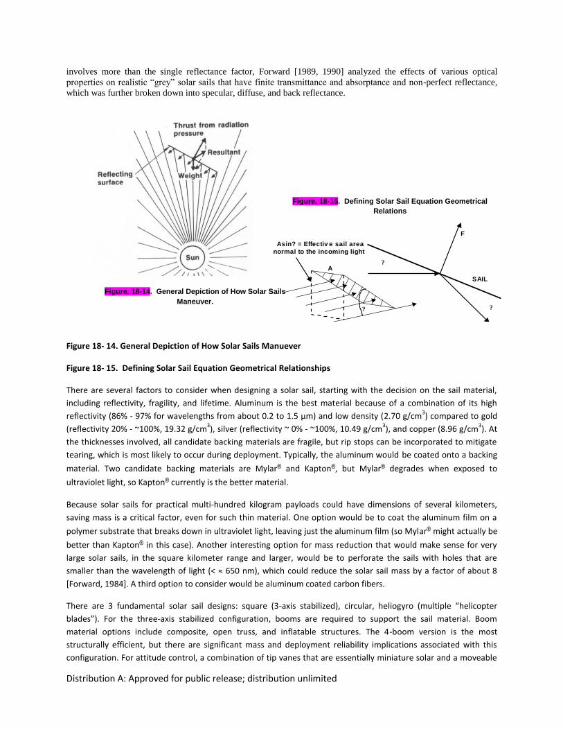
Distribution A: Approved for public release; distribution unlimited
involves more than the single reflectance factor, Forward [1989, 1990] analyzed the effects of various optical
properties on realistic “grey” solar sails that have finite transmittance and absorptance and non-perfect reflectance,
which was further broken down into specular, diffuse, and back reflectance.
Figure 18- 14. General Depiction of How Solar Sails Manuever
Figure 18- 15. Defining Solar Sail Equation Geometrical Relationships
There are several factors to consider when designing a solar sail, starting with the decision on the sail material,
including reflectivity, fragility, and lifetime. Aluminum is the best material because of a combination of its high
reflectivity (86% - 97% for wavelengths from about 0.2 to 1.5 μm) and low density (2.70 g/cm3) compared to gold
(reflectivity 20% - ~100%, 19.32 g/cm3), silver (reflectivity ~ 0% - ~100%, 10.49 g/cm
3), and copper (8.96 g/cm
3). At
the thicknesses involved, all candidate backing materials are fragile, but rip stops can be incorporated to mitigate
tearing, which is most likely to occur during deployment. Typically, the aluminum would be coated onto a backing
material. Two candidate backing materials are Mylar® and Kapton®, but Mylar® degrades when exposed to
ultraviolet light, so Kapton® currently is the better material.
Because solar sails for practical multi-hundred kilogram payloads could have dimensions of several kilometers,
saving mass is a critical factor, even for such thin material. One option would be to coat the aluminum film on a
polymer substrate that breaks down in ultraviolet light, leaving just the aluminum film (so Mylar® might actually be
better than Kapton® in this case). Another interesting option for mass reduction that would make sense for very
large solar sails, in the square kilometer range and larger, would be to perforate the sails with holes that are
smaller than the wavelength of light (< ≈ 650 nm), which could reduce the solar sail mass by a factor of about 8
[Forward, 1984]. A third option to consider would be aluminum coated carbon fibers.
There are 3 fundamental solar sail designs: square (3-axis stabilized), circular, heliogyro (multiple “helicopter
blades”). For the three-axis stabilized configuration, booms are required to support the sail material. Boom
material options include composite, open truss, and inflatable structures. The 4-boom version is the most
structurally efficient, but there are significant mass and deployment reliability implications associated with this
configuration. For attitude control, a combination of tip vanes that are essentially miniature solar and a moveable
Figure. 18-14. General Depiction of How Solar Sails
Maneuver.
Figure. 18-15. Defining Solar Sail Equation Geometrical
Relations
SAIL
?
?
F
A
?
Asin? = Effectiv e sail area
normal to the incoming light
Solar fluxh
ips.
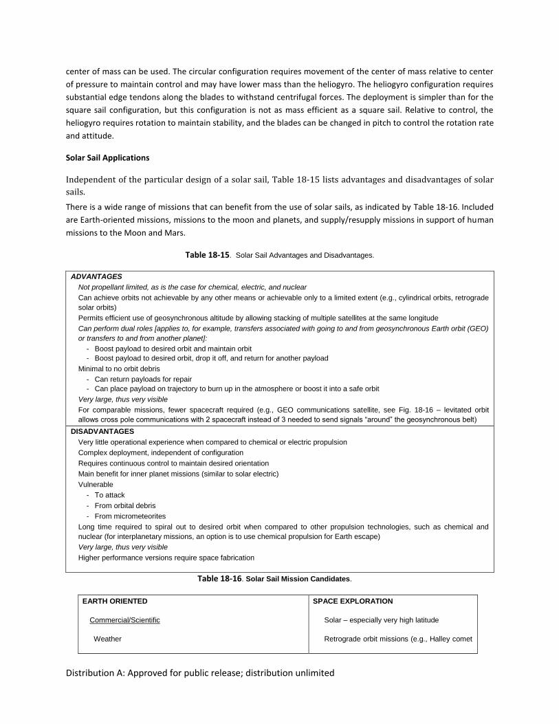
Distribution A: Approved for public release; distribution unlimited
center of mass can be used. The circular configuration requires movement of the center of mass relative to center
of pressure to maintain control and may have lower mass than the heliogyro. The heliogyro configuration requires
substantial edge tendons along the blades to withstand centrifugal forces. The deployment is simpler than for the
square sail configuration, but this configuration is not as mass efficient as a square sail. Relative to control, the
heliogyro requires rotation to maintain stability, and the blades can be changed in pitch to control the rotation rate
and attitude.
Solar Sail Applications
Independent of the particular design of a solar sail, Table 18-15 lists advantages and disadvantages of solar
sails.
There is a wide range of missions that can benefit from the use of solar sails, as indicated by Table 18-16. Included
are Earth-oriented missions, missions to the moon and planets, and supply/resupply missions in support of human
missions to the Moon and Mars.
Table 18-15. Solar Sail Advantages and Disadvantages.
ADVANTAGES
Not propellant limited, as is the case for chemical, electric, and nuclear
Can achieve orbits not achievable by any other means or achievable only to a limited extent (e.g., cylindrical orbits, retrograde
solar orbits)
Permits efficient use of geosynchronous altitude by allowing stacking of multiple satellites at the same longitude
Can perform dual roles [applies to, for example, transfers associated with going to and from geosynchronous Earth orbit (GEO)
or transfers to and from another planet]:
- Boost payload to desired orbit and maintain orbit
- Boost payload to desired orbit, drop it off, and return for another payload
Minimal to no orbit debris
- Can return payloads for repair
- Can place payload on trajectory to burn up in the atmosphere or boost it into a safe orbit
Very large, thus very visible
For comparable missions, fewer spacecraft required (e.g., GEO communications satellite, see Fig. 18-16 – levitated orbit
allows cross pole communications with 2 spacecraft instead of 3 needed to send signals “around” the geosynchronous belt)
DISADVANTAGES
Very little operational experience when compared to chemical or electric propulsion
Complex deployment, independent of configuration
Requires continuous control to maintain desired orientation
Main benefit for inner planet missions (similar to solar electric)
Vulnerable
- To attack
- From orbital debris
- From micrometeorites
Long time required to spiral out to desired orbit when compared to other propulsion technologies, such as chemical and
nuclear (for interplanetary missions, an option is to use chemical propulsion for Earth escape)
Very large, thus very visible
Higher performance versions require space fabrication
Table 18-16. Solar Sail Mission Candidates.
EARTH ORIENTED
Commercial/Scientific
Weather
SPACE EXPLORATION
Solar – especially very high latitude
Retrograde orbit missions (e.g., Halley comet

Distribution A: Approved for public release; distribution unlimited
Communications
Miscellaneous
- Solar storm warning
- Payload repair/replacement
Government/Military
Weather
Communications
Surveillance, especially at high latitudes – optical, signals
Satellite Inspection/Negation (i.e., anti-satellite)
Orbit transfer vehicle – transport payloads to/from desired orbits
rendezvous)
Inner planets – Venus, Mercury, Earth, Mars
Human mission supply/resupply – moon,
Mars
Outer planets – combine sail capabilities with
gravity assist
Interstellar missions – use gravity assist from
close flyby of the Sun to accelerate sail to
solar system escape velocity; replace solar
light source with laser source to push sail
Regarding the disadvantage listed in Table 18-15 associated with chemical and nuclear propulsion, this one needs
some amplification and expansion because the disadvantage is not necessarily a true disadvantage. Regarding
flight time, as solar sail technology improves, and assuming for interplanetary missions that chemical propulsion is
used to achieve Earth escape, absolute flight times can approach achievable flight times possible from chemical
propulsion. McInnes [2004] in a figure originally created by NASA/JPL provides data on flight times to Mars. From
that figure, the minimum flight time to Mars for a solar sail capable of achieving an acceleration of 1 mm/s2 is 370
days (+ about 100 days for capture and spiral down to a useful altitude). The corresponding minimum energy
(chemical propulsion) coplanar Hohmann Transfer time to Mars is approximately 259 days. The characteristic
Hohmann Transfer is representative of a flight time to Mars, but is not what realistically would be implemented.
However, if the launch date is missed (as was the case for the Mars Science Laboratory mission to Mars), the
impact will be a wait of 780 days for Earth and Mars to be aligned for another Hohmann Transfer trajectory flight
opportunity.
There are 2 Earth-oriented missions that are particularly fascinating, are extremely challenging technologically, and
demonstrate the unique capabilities of solar sails. One will be discussed in the paragraphs that follow, while the
other will be contained in a more complete discussion of solar sails that will be available on the web. They were
chosen also because of the increased focus on the utilization of space to better understand the Earth’s
environment that is certain to be an area of continuously increasing interest over time. Both of them were devised
by Forward. In the first instance, solar sails can use light pressure to levitate a payload (e.g., communications)
above or below the geosynchronous plane and maintain it there indefinitely at a fixed longitude, called a
cylindrical orbit [Forward, 1984, 1990]. More specifically, a levitated orbit allows continuous communications with
and/or observation of latitudes not possible with equatorial geosynchronous satellites or with high inclination low
altitude satellites. Even more intriguing, but technologically extremely challenging, for levitation distances > 1
Earth radius, only 2 satellites are required for cross-Earth communications (180 deg separation), rather than the
three minimum required for geosynchronous equatorial communications satellites (120 deg separation).
In the second instance, a solar sail maintains its position over a pole and can provide continuous service (e.g.,
broadcast, data transmission, weather services, and various types of observation) to any region on the Earth,
including polar regions, with only 1 spacecraft, called a statite orbit – [Forward, 1989, 1991, 1993]. See the website
for a more extended discussion and sample calculations.
Get More
Live Calc
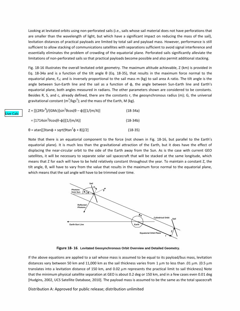
Distribution A: Approved for public release; distribution unlimited
Looking at levitated orbits using non-perforated sails (i.e., sails whose sail material does not have perforations that
are smaller than the wavelength of light, but which have a significant impact on reducing the mass of the sail),
levitation distances of practical payloads are limited by total sail and payload mass. However, performance is still
sufficient to allow stacking of communications satellites with separations sufficient to avoid signal interference and
essentially eliminates the problem of crowding of the equatorial plane. Perforated sails significantly alleviate the
limitations of non-perforated sails so that practical payloads become possible and also permit additional stacking.
Fig. 18-16 illustrates the overall levitated orbit geometry. The maximum altitude achievable, Z (km) is provided in
Eq. 18-34a and is a function of the tilt angle θ (Eq. 18-35), that results in the maximum force normal to the
equatorial plane, FP; and is inversely proportional to the sail mass m (kg) to sail area A ratio. The tilt angle is the
angle between Sun-Earth line and the sail as a function of φ, the angle between Sun-Earth line and Earth’s
equatorial plane, both angles measured in radians. The other parameters shown are considered to be constants.
Besides R, S, and c, already defined, there are the constants r, the geosynchronous radius (m); G, the universal
gravitational constant (m3/kgs
2); and the mass of the Earth, M (kg).
Z = [[(2RSr3)/(GMc)]sin
2θcos(θ – φ)][1/(m/A)] (18-34a)
= [1714sin2cos(-φ)][1/(m/A)] (18-34b)
θ = atan[[3tanφ + sqrt(9tan2φ + 8)]/2] (18-35)
Note that there is an equatorial component to the force (not shown in Fig. 18-16, but parallel to the Earth’s
equatorial plane). It is much less than the gravitational attraction of the Earth, but it does have the effect of
displacing the near-circular orbit to the side of the Earth away from the Sun. As is the case with current GEO
satellites, it will be necessary to separate solar sail spacecraft that will be stacked at the same longitude, which
means that Z for each will have to be held relatively constant throughout the year. To maintain a constant Z, the
tilt angle, θ, will have to vary from the value that results in the maximum force normal to the equatorial plane,
which means that the sail angle will have to be trimmed over time.
Figure 18- 16. Levitated Geosynchronous Orbit Overview and Detailed Geometry.
If the above equations are applied to a sail whose mass is assumed to be equal to its payload/bus mass, levitation
distances vary between 50 km and 11,000 km as the sail thickness varies from 1 m to less than .01 m. (0.5 m
translates into a levitation distance of 150 km, and 0.02 m represents the practical limit to sail thickness) Note
that the minimum physical satellite separation at GEO is about 0.2 deg or 150 km, and in a few cases even 0.01 deg
[Hudgins, 2002, UCS Satellite Database, 2010]. The payload mass is assumed to be the same as the total spacecraft
Reflected
Photons
Photons
from Sun
Sail
FP
F
Earth-Sun Line
Sail
Z
r
NCylindrical Orbit
Earth
Equatorial Orbit Plane
Fig. 13. Levitated Geosynchronous Orbit Overview and Detailed Geometry.
Live Calc
Distribution A: Approved for public release; distribution unlimited
mass for a GEO satellite, since the Sail/Payload/Bus will still require such subsystems as solar cells for power and a
communications subsystem. Launch masses for GEO satellites range from about 1,000 kg to 6,500 kg [Union of
Concerned Scientists (UCS) Satellite Database, 2010]. Assuming no change in launch capability would imply a
maximum bus/payload mass of 3,250 kg, which is what has been chosen. Clearly, very large sails are required.
There are some interesting general operational issues/challenges associated solar sails in general and with each of
these orbit types in particular. In the general category, reflection from the sails is not specular since the sail
material is not a perfect reflector. Hence some light is absorbed and some light is transmitted through the sail
material. Also, the sail is not perfectly flat. In the case of the levitated orbits, 2 times/day the sail is approximately
edge-on to the Earth so that there is potential communications impairment due to the physical blockage of the
spacecraft antenna by the sail itself. Candidate solutions to this situation include cutout in the sail to permit an
unobstructed communications path and putting the antennas on the tip vanes (at least for square sail
configurations). Additionally, 1 or 2 times/year the sail is shadowed by the Earth once/day at all levitated altitudes
that are less than about 4 Earth radii. The worst case time in the shadow is about 70 minutes, during which the
levitated altitude decreases by about 5%, which is not a major impact. Besides the long round trip light time of
several seconds previously mentioned, another operational issue for stationary polar orbits is the need for a clock
drive for the ground station antennas. However, the electronics are still relatively simple because the spacecraft
remains at almost the same range.
Finally, there are some regulatory issues to consider, in particular for the levitated orbits. Since multiple satellites
can be stacked at the same longitude, some regulation will be required relative to stacking separation distances.
Related to the stacking issue is who will control the physical separation of the satellites at a particular longitudinal
location to ensure that separation distances are maintained. Finally, as is already the case, care will be needed to
avoid communications interference.
A number of enabling technologies required to field a functionally useful solar sail are listed in Table 18-17.
Table 18-17. Enabling Technologies and Related Events.
SPACE FABRICATION
- Sail material
- Supporting structure/deployment methods
CAPABILITY TO REPAIR/UPGRADE SPACECRAFT
- Periodically replace part or all of sail
- Perforated substituted for part or all of non-perforated sail material
- Carbon fiber replacement for aluminized Kapton
UPGRADE/REPLACE PAYLOADS
- Change of mission
- Take advantage of technology improvements – continued advances in electronics will
cause payload components to shrink in mass/volume, while capabilities increase
Solar sails can perform unique scientific, commercial, and military missions, and the stage is set for near-term
space missions to validate deployment and control methodologies. Enabling technologies are still required to
permit high performance missions (e.g., levitated geosynchronous, stationary polar).
Distribution A: Approved for public release; distribution unlimited
Momentum Exchange. Traditional propulsion systems generate thrust by accelerating propellant and
ejecting it from the spacecraft. The useful lifetime of the propulsion system is completed once the store
of propellant has been exhausted. For a limited class of missions (certain formation flying missions with
satellite spacing of 10s of meters to over 1 km) it is conceptually possible to either bounce the
propellant (in the case of light) [Bae, 2008] or collect the ejected propellant and reuse it (in the case of
droplets) [Joslyn, 2010] between multiple satellites. In GEO the required thrust forces for such
applications are typically between 20 and 100 mN (1 km), while in LEO it is 100 to 1000 mN.
Liquid droplet propulsion systems send a stream of liquid droplets between two spacecraft to maintain a
separation force between them. One recently investigated concept uses a stream of low vapor pressure
silicon oil droplets between two satellites to produce thrust [Joslyn, 2010]. The droplet propulsion
system requires an order of magnitude less mass than traditional electric propulsion systems and two
orders of magnitude less power to accomplish this limited role. The liquid droplets typically have
diameters < 1.5 mm, speeds of about 5 m/s, and are fired at a frequency of about 0.5 Hz.
The highest achievable specific impulse is produced by photon emission: 3x10⁷ seconds. Photons are not
regularly used for propulsion because the power/thrust is prohibitively high. A photonic laser thruster
investigated by Bae [2007], however, bounces the laser multiple times between the emitting craft and a
reflector on the satellite that is being accelerated. The laser gain media is in between two mirrors (one
on each satellite) effectively creating a laser cavity in the entire gap between the two satellites. Proof-of-
concept experiments using mirrors with a reflectance of 0.99967 achieved a thrust amplification factor
of approximately 3000x achieving a thrust per unit power of approximately 20 mN/kW. Using a higher
reflectance mirror (R = 0.99995) a total thrust of 1.34mN could be generated with 10W (134 mN/kW).
The maximum separation that can be maintained between the two surfaces is estimated to be 1000 km.
Both classes of momentum exchange propulsion systems are at a relatively low level of development
and would require significant developmental efforts to yield flight-ready systems. It is unlikely that the
technology could be ready for application in the near-term.
18.7.2 Propulsion Systems for Small Satellites
Satellites with practical functionality are being constructed with ever decreasing dimensions. The
classes of small satellites are discussed in Sec. 2.1.8 and smallsats and cubesats are discussed in Secs.
25.3 and 25.4, respectively, so only relevant propulsion systems will be discussed in this section.
Propulsion systems are advantageous at all size scales and propulsion systems are being investigated for
the entire range of smallsats. Microsatellite propulsion requirements vary significantly, but often times
require very low impulse bits, high thrust levels, high thrust to noise levels, and significant Vs.
Solid and liquid chemical propulsion systems are being developed along with electrothermal,
electrostatic, and electromagnetic electric propulsion systems. The following discussion will focus
primarily on propulsion for microsatellites, or micropropulsion. Microsatellites represent the transition:
at 100 kg propulsion systems can be shrunken down versions of traditional propulsion systems while by
10 kg they are likely to be very different systems. The general rule of thumb for microsatellites is that
they have 1 W/kg of power available for propulsion. A total wet mass of the propulsion system itself is
Distribution A: Approved for public release; distribution unlimited
typically 10-20% of the total mass of the satellite. In general the smaller the satellite the more
integrated (sharing components with other subsystems) the propulsion system must be and the more
MEMS fabrication will be used. All of the support hardware must also be shrunk. Issues arising from
scaling propulsion systems to small dimensions produce a wide variety of concerns across the entire
range of micropropulsion systems as shown in Table 18-18.
Table 18-18.Common Micropropulsion Concerns.
Scaling Issue Concern Affected Thrusters
Small Length Scale High Heat Transfer Chemical
Passage Clogging Chemical
High Field Strengths Electric
Rarefied Flows Chemical
High Magnetic Fields Electromagnetic
Valve Leakage All
Voltage Limited Electric
High Surface to Volume Ratio Increase Heat Transfer Chemical
Increase Wall Losses Electric
Short Residence Times Limited Mixing Time Bipropellant
Frozen Flow Losses Chemical
Limited Vaporization Time Chemical
Reynold's Number 102 - 104 High Viscous Losses Chemical
Limited Mixing Chemical
Limited Materials/Manufacturing Relative Surface Roughness Chemical
Compatibility Limitations Chemical
Nonuniform Properties All
Propulsion systems from all classifications of full-scale propulsion have been successfully shrunk to the
scale relevant for microsatellites. Additional new types of propulsion systems, such as solid propellant
digital microthrusters, have also been developed, primarily for application at the smaller size scales
(near 10 kg). Table 18-19 lists typical performance numbers for micropropulsion systems that have been
demonstrated in the laboratory environment, but have typically not been flight qualified (TRL 3 - 6).
Positions left blank lack sufficient published information to draw conclusions. With a sufficient
developmental effort the majority of technologies listed in Table 18-19 could be flight ready in the next
10-20 years. Research is being conducted in the fields of nanopropulsion and picopropulsion, but in
general the technologies are not sufficiently developed to warrant inclusion in the table.
Table 18-19. Representative Relatively Mature Micropropulsion Systems [Scharfe, 2009]
Thruster Type Thrust [N] Isp [s] Power [W] Thruster Mass [kg]
Cold Gas 5x10⁻⁴ – 3 40 – 80 --- 0.01 – 1
Laser (Ignition) 1x10⁻³ – 1x10⁻² 37 – 100 --- ---
Monopropellant 1x10⁻⁶ – 1.5 100 – 230 0.01 – 0.5
Distribution A: Approved for public release; distribution unlimited
Decomposing Solid --- 230 --- ---
Electrothermal 0.22 50 – 250 3 – 300 0.1 – 1
Laser (Ablation) 1x10⁻⁶ 100 – 300 2 ---
Bipropellant 1x10⁻⁶ – 45 100 – 320 0.01 – 0.5
Laser (Plasma) 1x10⁻⁴ – 1x10⁻³ 500 – 1000 2 1
Solar Thermal 5.6x10⁻² – 1 200 – 1100 --- 10
Hollow Cathode 1x10⁻⁶ – 1x10⁻² 50 – 1200 5 – 1000 ---
Hall/Ion 4x10⁻⁴ – 2x10⁻² 300 – 3700 14 – 300 1
Electromagnetic 3x10⁻⁵ – 2x10⁻³ 200 – 4000 10 0.06 – 0.5
FEEP/Colloid 1x10⁻⁷ – 1.5x10⁻³ 450 – 9000 1 – 100 0.1 – 1
18.7.3 Propulsion Systems for Very Large Satellites
In contrast with smallsats, however, some categories of satellites continue to increase in size. GEO
communications satellites, for example, have steadily increased in size from approximately 35 kg with 28
Watts in 1963 (Syncom 2) to approximately 6910 kg (Terrestar-1) with up to 25 kW in total power in
2009 (Space Systems Loral 1300 series). It is assumed that there are no technical limitations to scaling
chemical propulsion systems to the larger sizes relevant for this range of satellites. High performance
electric propulsion systems at power levels of 100 – 200 kW, however, must be further developed.
Several candidate technologies have already been demonstrated in the lab and are sufficiently well
characterized to begin to make comparisons.
As mentioned in Sec. 18.6.3., a magnetoplasmadynamic (MPD) thruster is similar to an arcjet in physical
geometry, but it accelerates the propellant using the Lorentz force as the ionized propellant passes
through a high intensity arc. Two classifications of the MPD thruster exist depending on whether the
magnetic field is self-generated (self field MPD) or externally applied (applied field MPD). Applied field
MPDs are typically a more attractive option at lower power levels in 2009.
Hall thrusters for moderately sized spacecraft are a flight-qualified technology as described in Sec.
18.6.3. Traditional single channel Hall thrusters can become quite heavy at high-power levels, but it is
conceivable that an array of small thrusters could be assembled to achieve power levels of 100s of kW at
acceptable mass levels. The NASA-457M is chosen to represent the possibility of clustering existing
systems [Manzella, 2002]. One way to overcome this limitation is to use a Hall thruster with multiple
concentric channels. This allows the thruster channels to share the magnetic circuit and significantly
reduce the thruster footprint. Nested channel Hall (NHT) thrusters are under development.
The Variable Specific Impulse Magnetoplasma Rocket (VASIMR) was designed as a high-power electric
propulsion system so it has both high specific impulse (4000 – 5000 s) and high thrust (5 N). VASIMR has
three different stages: a helicon radiofrequency (RF) section to ionize the plasma, a second RF section
that uses ion cyclotron resonance frequency (ICRF) to further heat the plasma, and a superconducting
electromagnetic nozzle as the final stage. Ground testing of a laboratory model (VX-200) has validated
the expected performance levels of the device (t = 60 %, Isp = 5000 s, P = 200 kW). A VASIMR device
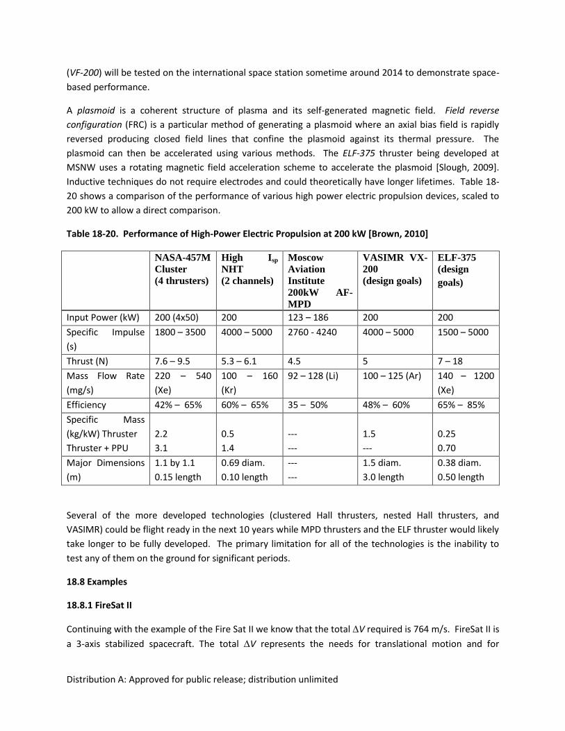
Distribution A: Approved for public release; distribution unlimited
(VF-200) will be tested on the international space station sometime around 2014 to demonstrate space-
based performance.
A plasmoid is a coherent structure of plasma and its self-generated magnetic field. Field reverse
configuration (FRC) is a particular method of generating a plasmoid where an axial bias field is rapidly
reversed producing closed field lines that confine the plasmoid against its thermal pressure. The
plasmoid can then be accelerated using various methods. The ELF-375 thruster being developed at
MSNW uses a rotating magnetic field acceleration scheme to accelerate the plasmoid [Slough, 2009].
Inductive techniques do not require electrodes and could theoretically have longer lifetimes. Table 18-
20 shows a comparison of the performance of various high power electric propulsion devices, scaled to
200 kW to allow a direct comparison.
Table 18-20. Performance of High-Power Electric Propulsion at 200 kW [Brown, 2010]
NASA-457M
Cluster
(4 thrusters)
High Isp
NHT
(2 channels)
Moscow
Aviation
Institute
200kW AF-
MPD
VASIMR VX-
200
(design goals)
ELF-375
(design
goals)
Input Power (kW) 200 (4x50) 200 123 – 186 200 200
Specific Impulse
(s)
1800 – 3500 4000 – 5000 2760 - 4240 4000 – 5000 1500 – 5000
Thrust (N) 7.6 – 9.5 5.3 – 6.1 4.5 5 7 – 18
Mass Flow Rate
(mg/s)
220 – 540
(Xe)
100 – 160
(Kr)
92 – 128 (Li) 100 – 125 (Ar) 140 – 1200
(Xe)
Efficiency 42% – 65% 60% – 65% 35 – 50% 48% – 60% 65% – 85%
Specific Mass
(kg/kW) Thruster
Thruster + PPU
2.2
3.1
0.5
1.4
---
---
1.5
---
0.25
0.70
Major Dimensions
(m)
1.1 by 1.1
0.15 length
0.69 diam.
0.10 length
---
---
1.5 diam.
3.0 length
0.38 diam.
0.50 length
Several of the more developed technologies (clustered Hall thrusters, nested Hall thrusters, and
VASIMR) could be flight ready in the next 10 years while MPD thrusters and the ELF thruster would likely
take longer to be fully developed. The primary limitation for all of the technologies is the inability to
test any of them on the ground for significant periods.
18.8 Examples
18.8.1 FireSat II
Continuing with the example of the Fire Sat II we know that the total V required is 764 m/s. FireSat II is
a 3-axis stabilized spacecraft. The total V represents the needs for translational motion and for
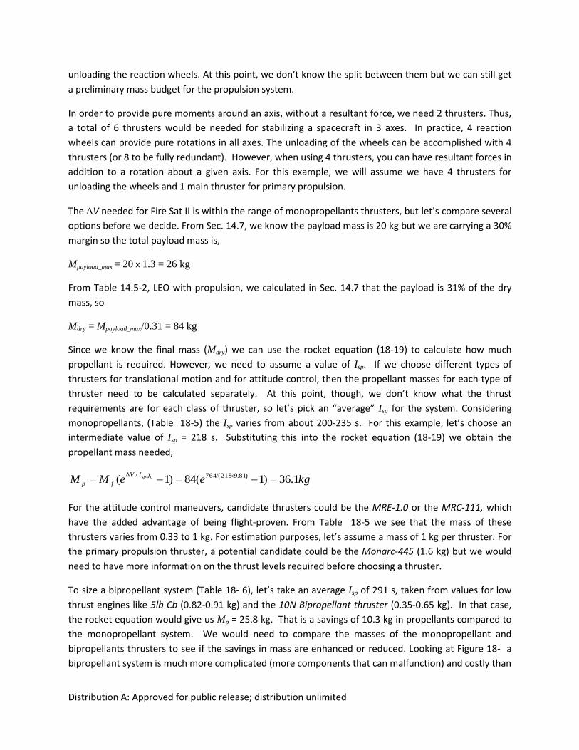
Distribution A: Approved for public release; distribution unlimited
unloading the reaction wheels. At this point, we don’t know the split between them but we can still get
a preliminary mass budget for the propulsion system.
In order to provide pure moments around an axis, without a resultant force, we need 2 thrusters. Thus,
a total of 6 thrusters would be needed for stabilizing a spacecraft in 3 axes. In practice, 4 reaction
wheels can provide pure rotations in all axes. The unloading of the wheels can be accomplished with 4
thrusters (or 8 to be fully redundant). However, when using 4 thrusters, you can have resultant forces in
addition to a rotation about a given axis. For this example, we will assume we have 4 thrusters for
unloading the wheels and 1 main thruster for primary propulsion.
The V needed for Fire Sat II is within the range of monopropellants thrusters, but let’s compare several
options before we decide. From Sec. 14.7, we know the payload mass is 20 kg but we are carrying a 30%
margin so the total payload mass is,
Mpayload_max = 20 x 1.3 = 26 kg
From Table 14.5-2, LEO with propulsion, we calculated in Sec. 14.7 that the payload is 31% of the dry
mass, so
Mdry = Mpayload_max/0.31 = 84 kg
Since we know the final mass (Mdry) we can use the rocket equation (18-19) to calculate how much
propellant is required. However, we need to assume a value of Isp. If we choose different types of
thrusters for translational motion and for attitude control, then the propellant masses for each type of
thruster need to be calculated separately. At this point, though, we don’t know what the thrust
requirements are for each class of thruster, so let’s pick an “average” Isp for the system. Considering
monopropellants, (Table 18-5) the Isp varies from about 200-235 s. For this example, let’s choose an
intermediate value of Isp = 218 s. Substituting this into the rocket equation (18-19) we obtain the
propellant mass needed,
kgeeMM ospgIV
fp 1.36)1(84)1( )81.9218/(764/
For the attitude control maneuvers, candidate thrusters could be the MRE-1.0 or the MRC-111, which
have the added advantage of being flight-proven. From Table 18-5 we see that the mass of these
thrusters varies from 0.33 to 1 kg. For estimation purposes, let’s assume a mass of 1 kg per thruster. For
the primary propulsion thruster, a potential candidate could be the Monarc-445 (1.6 kg) but we would
need to have more information on the thrust levels required before choosing a thruster.
To size a bipropellant system (Table 18- 6), let’s take an average Isp of 291 s, taken from values for low
thrust engines like 5lb Cb (0.82-0.91 kg) and the 10N Bipropellant thruster (0.35-0.65 kg). In that case,
the rocket equation would give us Mp = 25.8 kg. That is a savings of 10.3 kg in propellants compared to
the monopropellant system. We would need to compare the masses of the monopropellant and
bipropellants thrusters to see if the savings in mass are enhanced or reduced. Looking at Figure 18- a
bipropellant system is much more complicated (more components that can malfunction) and costly than
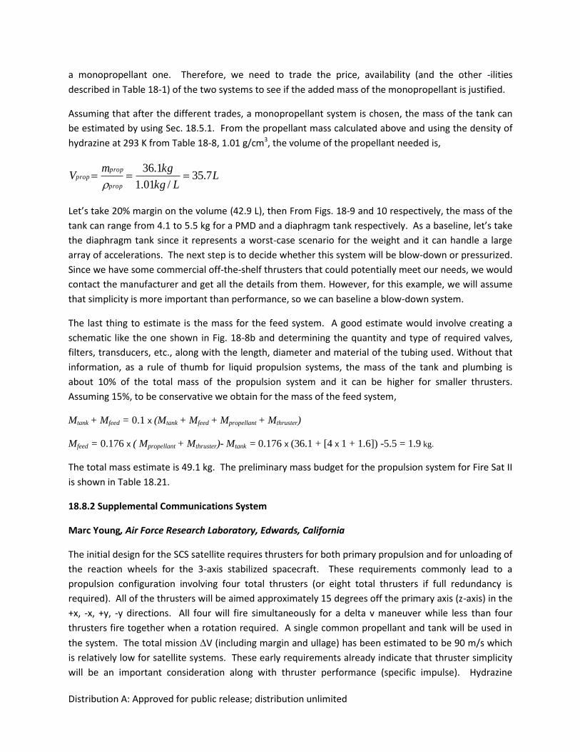
Distribution A: Approved for public release; distribution unlimited
a monopropellant one. Therefore, we need to trade the price, availability (and the other -ilities
described in Table 18-1) of the two systems to see if the added mass of the monopropellant is justified.
Assuming that after the different trades, a monopropellant system is chosen, the mass of the tank can
be estimated by using Sec. 18.5.1. From the propellant mass calculated above and using the density of
hydrazine at 293 K from Table 18-8, 1.01 g/cm3, the volume of the propellant needed is,
LLkg
kgmV
prop
propprop 7.35
/01.1
1.36
Let’s take 20% margin on the volume (42.9 L), then From Figs. 18-9 and 10 respectively, the mass of the
tank can range from 4.1 to 5.5 kg for a PMD and a diaphragm tank respectively. As a baseline, let’s take
the diaphragm tank since it represents a worst-case scenario for the weight and it can handle a large
array of accelerations. The next step is to decide whether this system will be blow-down or pressurized.
Since we have some commercial off-the-shelf thrusters that could potentially meet our needs, we would
contact the manufacturer and get all the details from them. However, for this example, we will assume
that simplicity is more important than performance, so we can baseline a blow-down system.
The last thing to estimate is the mass for the feed system. A good estimate would involve creating a
schematic like the one shown in Fig. 18-8b and determining the quantity and type of required valves,
filters, transducers, etc., along with the length, diameter and material of the tubing used. Without that
information, as a rule of thumb for liquid propulsion systems, the mass of the tank and plumbing is
about 10% of the total mass of the propulsion system and it can be higher for smaller thrusters.
Assuming 15%, to be conservative we obtain for the mass of the feed system,
Mtank + Mfeed = 0.1 x (Mtank + Mfeed + Mpropellant + Mthruster)
Mfeed = 0.176 x ( Mpropellant + Mthruster)- Mtank = 0.176 x (36.1 + [4 x 1 + 1.6]) -5.5 = 1.9 kg.
The total mass estimate is 49.1 kg. The preliminary mass budget for the propulsion system for Fire Sat II
is shown in Table 18.21.
18.8.2 Supplemental Communications System
Marc Young, Air Force Research Laboratory, Edwards, California
The initial design for the SCS satellite requires thrusters for both primary propulsion and for unloading of
the reaction wheels for the 3-axis stabilized spacecraft. These requirements commonly lead to a
propulsion configuration involving four total thrusters (or eight total thrusters if full redundancy is
required). All of the thrusters will be aimed approximately 15 degrees off the primary axis (z-axis) in the
+x, -x, +y, -y directions. All four will fire simultaneously for a delta v maneuver while less than four
thrusters fire together when a rotation required. A single common propellant and tank will be used in
the system. The total mission V (including margin and ullage) has been estimated to be 90 m/s which
is relatively low for satellite systems. These early requirements already indicate that thruster simplicity
will be an important consideration along with thruster performance (specific impulse). Hydrazine
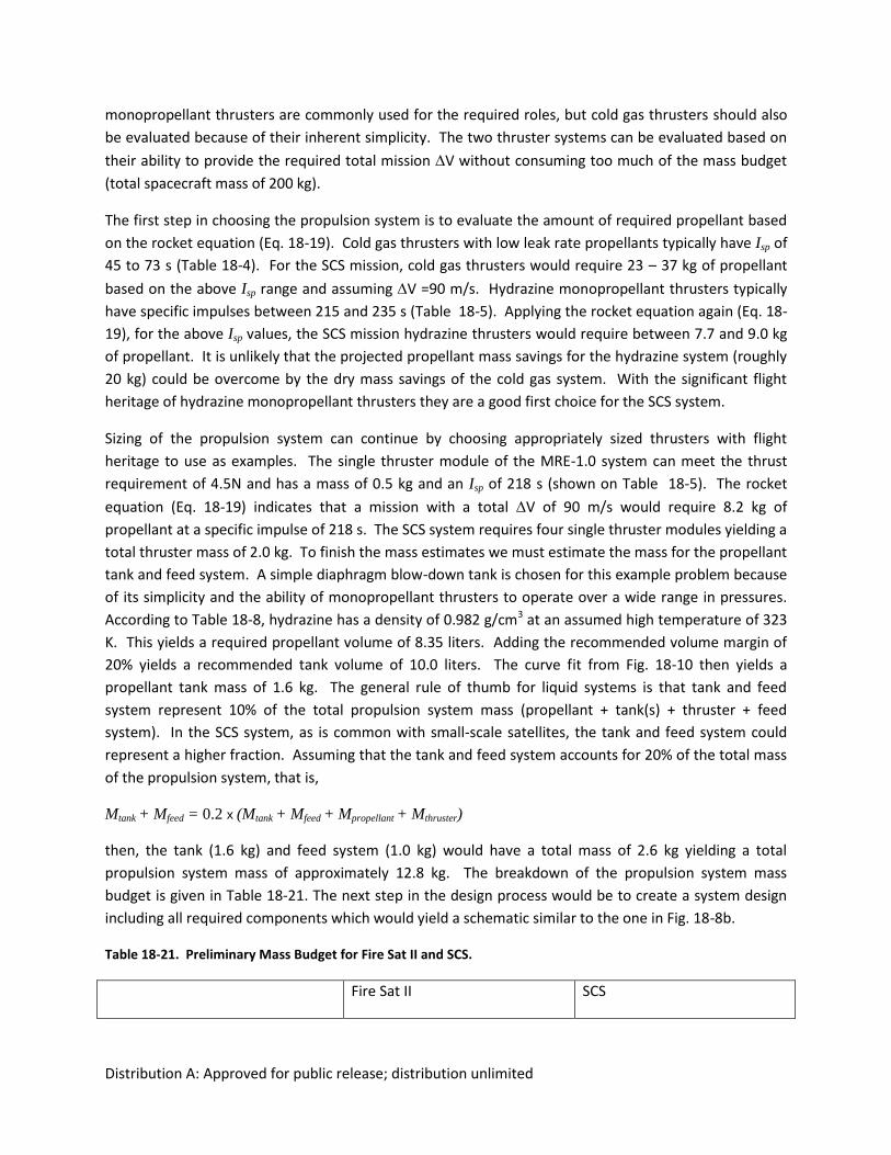
Distribution A: Approved for public release; distribution unlimited
monopropellant thrusters are commonly used for the required roles, but cold gas thrusters should also
be evaluated because of their inherent simplicity. The two thruster systems can be evaluated based on
their ability to provide the required total mission V without consuming too much of the mass budget
(total spacecraft mass of 200 kg).
The first step in choosing the propulsion system is to evaluate the amount of required propellant based
on the rocket equation (Eq. 18-19). Cold gas thrusters with low leak rate propellants typically have Isp of
45 to 73 s (Table 18-4). For the SCS mission, cold gas thrusters would require 23 – 37 kg of propellant
based on the above Isp range and assuming V =90 m/s. Hydrazine monopropellant thrusters typically
have specific impulses between 215 and 235 s (Table 18-5). Applying the rocket equation again (Eq. 18-
19), for the above Isp values, the SCS mission hydrazine thrusters would require between 7.7 and 9.0 kg
of propellant. It is unlikely that the projected propellant mass savings for the hydrazine system (roughly
20 kg) could be overcome by the dry mass savings of the cold gas system. With the significant flight
heritage of hydrazine monopropellant thrusters they are a good first choice for the SCS system.
Sizing of the propulsion system can continue by choosing appropriately sized thrusters with flight
heritage to use as examples. The single thruster module of the MRE-1.0 system can meet the thrust
requirement of 4.5N and has a mass of 0.5 kg and an Isp of 218 s (shown on Table 18-5). The rocket
equation (Eq. 18-19) indicates that a mission with a total V of 90 m/s would require 8.2 kg of
propellant at a specific impulse of 218 s. The SCS system requires four single thruster modules yielding a
total thruster mass of 2.0 kg. To finish the mass estimates we must estimate the mass for the propellant
tank and feed system. A simple diaphragm blow-down tank is chosen for this example problem because
of its simplicity and the ability of monopropellant thrusters to operate over a wide range in pressures.
According to Table 18-8, hydrazine has a density of 0.982 g/cm3 at an assumed high temperature of 323
K. This yields a required propellant volume of 8.35 liters. Adding the recommended volume margin of
20% yields a recommended tank volume of 10.0 liters. The curve fit from Fig. 18-10 then yields a
propellant tank mass of 1.6 kg. The general rule of thumb for liquid systems is that tank and feed
system represent 10% of the total propulsion system mass (propellant + tank(s) + thruster + feed
system). In the SCS system, as is common with small-scale satellites, the tank and feed system could
represent a higher fraction. Assuming that the tank and feed system accounts for 20% of the total mass
of the propulsion system, that is,
Mtank + Mfeed = 0.2 x (Mtank + Mfeed + Mpropellant + Mthruster)
then, the tank (1.6 kg) and feed system (1.0 kg) would have a total mass of 2.6 kg yielding a total
propulsion system mass of approximately 12.8 kg. The breakdown of the propulsion system mass
budget is given in Table 18-21. The next step in the design process would be to create a system design
including all required components which would yield a schematic similar to the one in Fig. 18-8b.
Table 18-21. Preliminary Mass Budget for Fire Sat II and SCS.
Fire Sat II SCS
Distribution A: Approved for public release; distribution unlimited
Propellant (kg) 36.1 8.2
Thrusters (kg) 5.6 2.0
Tank (kg) 5.5 1.6
Feed System (kg) 1.9 1.0
Total Mass of Propulsion System
(kg)
49.1 12.8
REFERENCES
1. Aerojet Redmond. 2003. MR-502A Improved Electrothermal Hydrazine Thruster (IMPEHT) Data Sheet. Redmond, WA: Aerojet Redmond. April.
2. Aerojet Redmond. 2003. MR-509 Low Power Arcjet System Data Sheet. Redmond, WA: Aerojet Redmond. April.
3. Aerojet Redmond. 2003. MR-510 Arcjet Thruster and Cable Assembly Data Sheet. Redmond, WA: Aerojet Redmond. April.
4. Aerojet Redmond. 2003. BPT-4000 Hall Effect Thruster Data Sheet. Redmond, WA: Aerojet Redmond, April.
5. AIAA. 1999. “AIAA Standard for Space Systems – Metallic Pressure Vessels, Pressurized Structures, and Pressure Components,” S-080-1998e.
6. AIAA. 2006. “AIAA Standard for Space Systems – Composite Overwrapped Pressure Vessels (COPVs),” S-081A-2006e. Revised.
7. Air Force Space Command. 2004. “Range safety user requirements manual – volume 2 flight safety requirements,“ Manual 91-710 Vol. 2 (AFSPCMAN 91-710 V2).
8. Astrium EADS. 2010. cs.astrium.eads.net. April.
9. Astrium EADS. 2010. : http://cs.astrium.eads.net/sp/SpacecraftPropulsion/MonopropellantThrusters.html. October.
10. Astrium EADS. 2010. http://cs.astrium.eads.net/sp/LauncherPropulsion/Brochures/aestus.pdf. October.
11. Astrium EADS. 2010. http://cs.astrium.eads.net/sp/SpacecraftPropulsion/Bipropellant_Thrusters/400N_Bipropellant_Apogee_Engine_S400.html. October.
12. Astrium EADS. 2010. http://cs.astrium.eads.net/sp/Brochures/PDF/10N%20Bipropellant%20Thruster.pdf. October.
Distribution A: Approved for public release; distribution unlimited
13. Bae, Y. 2007. "Photonic Laser Propulsion: Photon Propulsion Using and Active Resonant Optical Cavity," paper no. AIAA-2007-6131 presented at the AIAA Space 2007 Conference. Long Beach, CA, September 18-20.
14. Bae, Y. 2008. “Photonic Laser Propulsion: Proof-of-Concept Demonstration,” Journal of Spacecraft and Rockets. 45:153-155.
15. Balaam, P. and M. M. Micci. 1995. “Investigation of Stabilized Resonant Cavity Microwave Plasmas for Propulsion." Journal of Propulsion and Power. Vol. 11, No. 5, September-October 1995, pp. 1021.
16. Benson, S., L. A. Arrington, W. A., Hoskins, N. J. Meckel.1999. “Development of a PPT for the EO-1 Spacecraft," paper no. AIAA-1999-2276 presented at the 35th Joint Propulsion Conference and Exhibit. Los Angeles, CA, June 20-24.
17. Bergonz, F. 1982. Manned maneuvering unit, NASA Johnson Space Center Satellite Serv. Workshop, Vol. 1 p 32-43 (SEE N83-11175 02-16).
18. Bolonkin, A. 2006. Non-Rocket Space Launch and Flight. Oxford, UK: Elsevier.
19. Brown, C. D. 1996. Spacecraft Propulsion, AIAA Education Series.
20. Brown, C.D. 2002. Elements of Spacecraft Design. AIAA Education Series.
21. Brown, D. L. 2010. Personal Communication.
22. Burton, R. L. and P. J. Turchi. 1998. “Pulsed Plasma Thruster." Journal of Propulsion and Power. Vol. 14, No. 5, September-October, pp. 716-735.
23. Busek Company. 2007. Low Power Hall Effect Thruster Systems Data Sheet, 2nd ed. Natik, MA:Busket Company.
24. Busek Company. 20087. High Power Hall Effect Thruster Systems Data Sheet. Natik, MA:Busek Company.
25. Busek Company. 2007. Micro Pulsed Plasma Thruster Data Sheet. Natik, MA:Busek Company.
26. Bzibziak, R. 2000. “Update of Cold Gas Propulsion at Moog,” paper no. AIAA 2000-3718 presented at the 36th Joint Propulsion Conference and Exhibit. Huntsville, AL, July 17-19.
27. Bzibziak, R. 2010. Private Communication.
28. Cassidy, R. J., W. A. Hoskinsand C. E. Vaughn. 2002. “Development and Flight Qualification of a 26-Kilowatt Arcjet Propulsion Subsystem." Journal of Propulsion and Power. Vol. 18, No. 4, July-August, pp. 740-748.
29. Chiaverini, M. J., K. K. Kuo, eds. 2007. Fundamentals of Hybrid Rocket Combustion and Propulsion. Progress in Astronautics and Aeronautics, Vol. 218.
30. Choueriri, E. Y. 2004. “A Critical History of Electric Propulsion: The First 50 Years (1906-1956)." Journal of Propulsion and Power. Vol. 20, No. 2, March-April.
31. Choueriri, E. Y. and K. A. Polzin. 2006. “Faraday Acceleration with Radio-Frequency Assisted Discharge." Journal of Propulsion and Power. Vol. 22, No. 3, May-June, pp. 611-619.
32. Clark, J. D. 1972. Ignition! An Informal History of Liquid Rocket Propellants. New Brunswick, NJ: Rutgers University Press.
Distribution A: Approved for public release; distribution unlimited
33. Cole, J., I. Silvera, J. Foote. 2008. “Conceptual Launch Vehicles Using Metallic Hydrogen Propellant,” in Proceedings of the Space Technology and Applications International Forum-STAIF 2008, ed. M.S. El-Genk, Melville, NY: AIP, Vol. 969, pp. 977-984.
34. Dawnson, M., G. Brewster, C. Conrad., M. Kilwine, B. Chenevert, O. Morgan. 2007. “Monopropellant Hydrazine 700 lbf Throttling Terminal Descent Engine for Mars Science Laboratory,” paper no. AIAA 2007-5481 presented at the 43rd AIAA/ASME/SAE/ASEE Joint Propulsion Conference and Exhibit. Cincinnati, OH, July 8-11.
35. Dornheim, M. A. 2003. “Ideal hybrid fuel is … wax?” Aviation Week & Space Technology. February 3, p.50.
36. Dornheim, M. A. 2003. “Burt Rutan’s quest for space.” Aviation Week & Space Technology. April 21, p.64.
37. Dressler, R., Y. Chu, D. J. Levandier. 2000. “Propellant Alternatives for Ion and Hall EffectThrusters," paper no. AIAA-2000-0602 presented at the 38th Aerospace Sciences Meeting and Exhibit. Reno, NV. January 10-13.
38. Drenning, C. K., R. J. Phillips, R.V. Loustau, F.L. Falconer. 1978. “Design and Fabrication of Space Shuttle Reaction Control Thruster Insulated Scarf Nozzles,” paper no. AIAA 1978-1006 presented at the 14th AIAA and SAE Joint Propulsion Conference. Las Vegas, NV, July 25-27.
39. Dyer, J., E. Doran, Z. Dunn, K. Lohner, C. Bayart, A. Sadhwani, G. Zilliac, B. Cantwell, A. Karabevoglu. 2007. “Design and Development of a 100km Nitrous Oxide/Paraffin Hybrid Rocket Vehicle,” paper no. AIAA 2007-5362 presented at the 43rd AIAA and SAE Joint Propulsion Conference. Cincinnati, OH, July 8-11.
40. Evans, B., E. Boyer, K. Kuo, G. Risha, M. Chiaverini. 2009. “Hybrid Rocket Investigations at Penn State University’s High Pressure Combustion Laboratory: Overview and Recent Results,” paper no. AIAA-2009-5349 presented at the 45th AIAA/ASME/SAE/ASEE Joint Propulsion Conference. Denver, CO, August 2-5.
41. Ferguson, H. and J. S. Sovey, J. S. 1967. Performance Tests of a 1/2-Millipound (2.2 mN) Ammonia Resistojet Thruster System. Tech. rep., NASA Lewis Research Center.
42. Frei T. E., T.L. Fischer, J. M. Weiss. 2001. “Mars Polar Lander Thruster Cold Start Validation Testing,” paper no. AIAA-2001-3261 presented at the 37th AIAA/ASME/SAE/ASEE Joint Propulsion Conference. Salt Lake City, UT, July 8-11.
43. General Electric Space Division. 1978. Landsat 3 Reference Manual, Philadelphia, PA.
44. Gesto, F., B. Blackwell, C. Charles, R. Boswell. 2006. “Ion Detachment in the Helicon Double-Layer Thruster Exhaust Beam." Journal of Propulsion and Power. Vol. 22, No. 1, January-February, pp. 24-30.
45. Goddard, E. C. and G. E. Penray (editors). 1970. The Papers of Robert H. Goddard. McGraw-Hill Book Company.
46. Goebel, D. M. and I. Katz. 2008. Fundamentals of Electric Propulsion: Ion and Hall Thrusters. Vol. 1, JPL Space Science and Technology Series, John Wiley and Sons, Inc., New York, 1st ed.
47. Henshall, P., P. Palmer. 2006. "Solar Thermal Propulsion Augmented with Fiber Optics: Technology Development," paper no. AIAA-2006-4874 presented at the 42nd AIAA/ASME/SAE/ASEE Joint Propulsion Conference. Sacramento, CA, July 9-12.
Distribution A: Approved for public release; distribution unlimited
48. Hill, P., C. Peterson. 1992. Mechanics and Thermodynamics of Propulsion, 2nd Edition. Addison-Wesley Publishing Company.
49. Hill, C. S. 1980. “SSRCS First Flight Certification Testing,” paper no. AIAA 1980-1130 presented at the 16th SAE and ASME Joint Propulsion Conference. Hartford, CT, June 30-July 2.
50. Hofer, R. R. and A. D. Gallimore. 2006. “High Specific Impulse Hall Thrusters, Part 2: Efficiency Analysis." Journal of Propulsion and Power. Vol. 22, No. 4, July-August, pp. 732-740.
51. Holmberg N. A., R.P. Faust, H.M. Holt. 1980. Viking ’75 Spacecraft Design and Test Summary, NASA Reference Publication 1027.
52. Hruby, V., J. Kolencik, K. D. Annen, R. C. Brown. 1997. “Methane Arcjet Experiments," paper no. AIAA-1997-2427 presented at the 28th AIAA Plasma Dynamics and Lasers Conference. Atlanta, GA, June 23-25.
53. Humble, R. W., G. N. Henry, W. J. Larson. 1995. Space Propulsion Analysis and Design. Space Technology Series. 1st Edition, New York, NY: McGraw-Hill.
54. Huzel, D. K., D. H. Huang. 1992. Modern Engineering for Design of Liquid-Propellant Rocket Engines, AIAA.
55. Isakowitz S. J., J. B. Hopkins, J. P. Hopkins Jr. 2004. International Reference Guide to Space Launch Systems, 4th edition. AIAA.
56. Ito, T., N. Gascon, S. Crawford, M. A. Cappelli. 2007. “Experimental Characterization of a Micro-Hall Thruster." Journal of Propulsion and Power. Vol. 23, No. 5, September-October, pp. 1069-1074.
57. Jackman C.H., D.B. Considine, E. L. Fleming. 1996. “Space shuttle’s impact on the stratosphere: an update”. J of Geophysical Research. Vol. 101, No. D7, pp 12,523-12,529.
58. Jacobson, D. and D. Manzella. 2003. “50 kW Class Krypton Hall Thruster Performance," paper no. AIAA-2003-4550 presented at the 39th Joint Propulsion Conference and Exhibit. Huntsville, AL, July 20-23.
59. Jahn, R., 1968. Physics of Electric Propulsion. McGraw-Hill.
60. Joslyn, T. B., A.K. Ketsdever. 2010. "Constant Momentum Exchange between Microspacecraft Using Liquid Droplet Thrusters," paper no. AIAA-2010-6966 presented at the 46th AIAA/ASME/SAE/ASEE Joint Propulsion Conference and Exhibit. Nashville, TN, July 25-28.
61. Kare, J.T. 2002. “Near-Term Laser Launch Capability: The Heat Exchanger Thruster,” in Proceedings of the First International Symposium on Beamed Energy Propulsion, ed. A.V. Pakhomov, AIP Conference Proceedings 664, Melville, NY, pp. 442-453.
62. Ketsdever, A. 2000. “System Considerations and Design Options for Microspacecraft Propulsion Systems”, Micropropulsion for small spacecraft. Progress in Astronautics and Aeronautics, Vol. 187, edited by M. Micci and A. Ketsdever, AIAA Reston, VA, Chapter 4.
63. Ketsdever, A. D., M. P. Young, J. B. Mossman, A. P Pancotti. 2010. "Overview of Advanced Concepts for Space Access." Journal of Spacecraft and Rockets. 47:238-250.
64. Kodys, A. D., and E. Y. Choueiri. 2005. "A Critical Review of the State-of-the-Art in the Performance of Applied-field Magnetoplasmadynamic Thrusters," paper no. AIAA-2005-4247 presented at the 41st AIAA/ASME/SAE/ASEE Joint Propulsion Conference. Tucson, AZ, July 11-13.
Distribution A: Approved for public release; distribution unlimited
65. Legge, R. S., P. Lozano, M. Martinez-Sanchez, M. 2007. “Fabrication and Characterization of Porous Metal Emitters for Electrospray Thrusters," paper no. IEPC-2007-145 presented at the 43rd Joint Propulsion Conference and Exhibit. Florence, Italy, September 17-20.
66. Lichon, P. G. and J. M. Sankovic. 1996. “Development and Demonstration of a 600-Second Mission-Average Isp Arcjet." Journal of Propulsion and Power. Vol. 12, No. 6, November-December, pp. 1018-1025.
67. Linnell, J. A. and A. D. Gallimore. 2006. “Efficiency Analysis of a Hall Thruster Operating with Krypton and Xenon." Journal of Propulsion and Power. Vol. 22, No. 6, November-December, pp. 1402-1418.
68. Lockheed Martin Corp. 2005.
(http://www.lockheedmartin.com/news/press_releases/2005/LOCKHEEDMARTINSUCCESSFULLY
TESTFIRES.html). November.
69. Loeb, H. W., D. Feili, B. K. Meyer.2004. “Development of RIT Microthrusters”, paper no. No. IAC-04-S.4.04 presented at the 55thInternational Astronautical Congress, American Institute of Aeronauticsand Astronautics, Vancouver, October.
70. Manzella, D., R. Jankovsky, R. Hofer. 2002. "Laboratory Model 50 kW Hall Thruster," paper no. AIAA-2002-3676 presented at the 38th AIAA/ASME/SAE/ASEE Joint Propulsion Conference, Indianapolis, IN, July 7-10.
71. Martin, A. and R. Eskridge. 2005. “Electrical Coupling Efficiency of Inductive Plasma Accelerators." Journal of Physics D: Applied Physics. Vol. 38, November, pp. 4168-4179.
72. McRight, P., C. Popp, C. Pierce, A. Turpin, W. Urbanchock. 2005. “Confidence Testing of Shell-405 Catalysts in a Monopropellant Hydrazine Thruster,” paper no. AIAA-2005-3952 presented at the 41st AIAA/ASME/SAE/ASEE Joint Propulsion Conference. Tucson, AZ, July 10-13.
73. Messerschimd, E. W., D. M. Zube, K.Meinzer, H. L. Kurtz. 1996. “Arcjet Developmentfor Amateur Radio Satellite." Journal of Spacecraft and Rockets. Vol. 33, No. 1, January-February, pp. 86-91.
74. Micci, M. M. and Ketsdever, A. D., Micropropulsion for Small Spacecraft, Progress in Astronautics and Astronautics, V-187, American Institute of Aeronautics and Astronautics, 2000.
75. Mikellides, P. G. and C. Neilly. 2007. “Modeling and Performance Analysis of the Pulsed Inductive Thruster." Journal of Propulsion and Power. Vol. 23, No. 1, January-February, pp. 51-58
76. Moog. 2010. http://www.moog.com/products/propulsion- controls/spacecraft/components/cold-gas-thrusters/solenoid-actuated. November.
77. Morgan, J. A. 1997. "A Brief History of Cannon Launch," paper no. AIAA-1997-3138 presented at the 33rd AIAA/ASME/SAE/ASEE Joint Propulsion Conference. Seattle, WA, July 6-9.
78. Morrisey, D. C. 1992. “Historical perspective - Viking Mars Lander propulsion.“ Journal of Propulsion and Power. Vol. 8, No. 2, pp. 320-331.
79. Morring, Jr., F. 2003. “Test puts Hybrid Rockets back on the Table.” Aviation Week & Space Technology. February 3, p.50.
Distribution A: Approved for public release; distribution unlimited
80. Myrabo, L., D. Messitt, F. Mead. 1998. “Ground and Flight Tests of a Laser-Boosted Vehicle,” paper no. AIAA-1998-1001 presented at the 36th Aerospace Sciences Meeting and Exhibit. Reno, NV, Jan. 12-15.
81. National Research Council. 1998. Assessment of Exposure-Response Functions for Rocket-Emission Toxicants, Subcommittee on Rocket-Emission Toxicants. Committee on Toxicology, Board on Environmental Studies and Toxicology, Commission on Life Sciences, National Academy Press, Washington, D.C.
82. Norris, G. 2009. “Virgin Galactic’s SpaceShip Two Revealed in Desert Rollout.” Aviation Week & Space Technology. Dec. 14, p.37
83. Northrop Grumman Space Technology; Propulsion Systems. 2010. http://www.as.northropgrumman.com/products/monoprpellant_thrust/index.html. November.
84. Northrop Grumman Space Technology; Propulsion Systems. 2010. http://www.as.northropgrumman.com/products/bipropellant_engines/index.html. November.
85. Oda, Y., K. Komurasaki, K.Takahashi,A. Kasugai, K. Sakamoto. 2006. “Plasma Generation Using High-Power Millimeter-Wave Beam and Its Application for Thrust Generation.” J. Appl. Phys. 100: 113307.
86. Parkin, K.L. 2006. “The Microwave Thermal Thruster and Its Application to the Launch Problem,” PhD Thesis, California Institute of Technology.
87. Peterson, P., D. Jacobson, D. Manzella, J. John, J. 2005. “The Performance and Wear Characterization of a High-Power High-Isp NASA Hall Thruster," paper no. AIAA-2005-4243 presented at the 41st Joint Propulsion Conference and Exhibit. Tucson, AZ, July 10-13.
88. Phipps, C., J. Luke, T. Lippert, M. Hauer, A. Wokum. 2004. “Micropropulsion Using a Laser Ablation Jet." Journal of Propulsion and Power. Vol. 20, No. 6, November-December, pp. 1000-1011.
89. Phipps, C. R. 2006. Laser Ablation and Its Applications. Springer-Verlag, New York.
90. Pidgeon, D. J., R. L. Corey, B. Sauer, M. L. Day. 2006. “Two Years On-Orbit Performance of SPT-100 Electric Propulsion," paper no. AIAA-2006-5353 presented at the 24th International Communications Satellite Systems Conference. San Diego, CA, June 11-14.
91. Poehlmann, F. and M. A. Cappelli. 2007. “The Deflagration-Detonation Transition in Gas-FedPulsed Plasma Accelerators," paper no. AIAA-2007-5263 presented at the 43rd Joint Propulsion Conference and Exhibit. Cincinnati, OH, July 8-11.
92. “Projects, Organizations, and Missions.” Online. Available http://www.ugcs.caltech.edu/~diedrich/solarsails/links/, July 14, 2002.
93. QinetiQ. 2004.GOCE T5 Based Electric Propulsion System Data Sheet. United Kingdom:QinetiQ.
94. Schapell, D. T., E. Scarduffa, P. Smith, N. Solway. 2005. “Advances in Marotta Electric and Small Satellite Propulsion Fluid Control Activities,” paper no. AIAA-2005-4055 presented at the 41st Joint Propulsion Conference and Exhibit. Tucson, AZ, July 10-13.
95. Semenkin, A., A. Kochergin, A. Rusakov, V.Bulaev, J.Yuen, J. Shoji, C.Garner, D. Mazella. 1999.“Development Program and Preliminary Results of the TAL-110 Thruster," paper no. AIAA-1999-2279 presented at the 35th Joint Propulsion Conference and Exhibit. Los Angeles, CA, June 20-24.
Distribution A: Approved for public release; distribution unlimited
96. Simmons, F.S. 2000. Rocket Exhaust Plume Phenomenology. The Aerospace Press.
97. Slough, J., D. E. Kirtley,T. Weber. 2009. “Pulsed Plasmoid Propulsion: The ELF Thruster,” paper no. IEPC-2009-265, presented at the International Electric Propulsion Conference. Ann Arbor, MI, Sept. 20-24.
98. Smith, P. 2006. “Resistojet Thruster Design and Development Programme,” paper no. AIAA-2006-5210 presented at the 42nd Joint Propulsion Conference and Exhibit. Sacramento, CA, July 9-11.
99. Smith, K. L., M.S. Alexander, M. D. Paine, J. P. W. Stark. 2009. “Scaling of a Colloid Thruster System for MicroNewton to MilliNewton Thrust Levels," paper no. IEPC-2009-112 presented at the 30thInternational Electric Propulsion Conference. Ann Arbor, MI, September 20-24.
100. Stechman R. C. 1985. “Modification of the Space Shuttle Primary Thruster (870 lbf) for Apogee and Perigee Kick Stages,” paper no. AIAA 1985-1222 presented at the 21st SAE, ASME and ASEE Joint Propulsion Conference. Monterey, CA, July 8-10.
101. Stechman R. C. 1990. “Development History of the 25 lbf (110 Newton) Space Shuttle Vernier Thruster,” paper no. AIAA 1990-1837 presented at the 26th SAE, ASME and ASEE Joint Propulsion Conference. Orlando, FL, July 16-18.
102. Stechman C. R., P. Woll, R. Fuller, A. Colette. 2000. “A High Performance Liquid Rocket Engine for Satellite Main Propulsion,” paper AIAA 2000-3161 presented at the 36th AIAA/ASME/SAE/ASEE Joint Propulsion Conference and Exhibit. Huntsville, AL, July 16-19.
103. Stwalley, W. 1991. "Survey of Potential Novel High Energy Content Metastable Materials," in Proceedings of the High Energy Density Matter (HEDM) Conference. Albuquerque, NM, February 24-27, (Phillips Lab PL-CP-91-3003, p. 3).
104. Sullivan, D. J., J. F. Kline, R. B. Miles, S. H. Zaidi. 2004. “A 300 W Microwave Thruster Design and Performance Testing," paper no. AIAA-2004-4122 presented at the 40th Joint Propulsion Conference and Exhibit. Fort Lauderdale, FL, July 11-14.
105. Sund, D. C., C.S. Hill.1979. “Reaction Control System Thrusters for Space Shuttle Orbiter,” paper no. AIAA 1979-1144 presented at the 15th SAE and ASME Joint Propulsion Conference. Las Vegas, NV June 18-20.
106. Surrey Satellite Technologies, Ltd. 2007.SSTL Low Power Resistojet Data Sheet SSTL-9029-02. United Kingdom: Surrey Satellite Technologies. August.
107. Sutton, G. P. and O. Biblarz. 2010. Rocket Propulsion Elements, John Wiley and Sons, Inc., 7th ed.
108. Sweetman B., (editor). 2006. Jane’s Space Directory, 2006-2007. Jane’s Information Group.
109. Sweetman, B., (editor). 2008. Jane’s Space Systems and Industry 2008-2009. Jane's Information Group.
110. Swink, D. G., O. M. Morgan, J. C. Robinson. 1999. “Design and analysis of a low-cost reaction control system for GPS llF,” paper no. AIAA 1999-2469, presented at the 35th Joint Propulsion Conference and Exhibit. Los Angeles, CA, June 20-24.
111. Tajmar, M. 2003. Advanced Space Propulsion Systems. Austria, Springer-Verlag.
112. Takao, Y., H. Kataharada, T.Miyamoto, H.Masui,N.Yamamoto, H. Nakashima. 2006. “Performance Test of Micro Ion Thruster Using Microwave Discharge." Vacuum. Vol. 80, No. 11-12, September, pp. 1239-1243.
Distribution A: Approved for public release; distribution unlimited
113. Thompson, D. 2001. “Amine Azides used as monopropellants”, US Patent 6,299,654 B1.
114. Thompson P. A. 1972. Compressible Fluid Dynamics, McGraw-Hill, Inc.
115. Tikhonov, V. B., S. A. Semenkin, J. R. Brophy, J. E. Polk. 1997. “Performance of 130kWMPD Thruster with an External Magnetic Field and Li as Propellant," paper no. IEPC-1997-117 presented at the 25th International Electric Propulsion Conference. Cleveland, OH, August 24-28.
116. Tishkoff, J. M., and M. R. Berman. 2002. "Air Force Basic Research in Propellants and Combustion," paper no. AIAA-2002-0901 presented at the 40th AIAA Aerospace Sciences Meeting. Reno, NV, Jan. 14-17.
117. Toki, K., Y. Shimizu, K. Kurki. 2000. “On-Orbit Demonstration of a Pulsed Self-Field Magnetoplasmadynamic Thruster System." Journal of Propulsion and Power. Vol. 16, No. 5, September-October.
118. Tsander, F. A., From A Scientific Heritage, NASA TTF-541, 1967 (quoting from author 1924 report).
119. Tsiolkovskii, K. E., Extension of Man Into Outer Space, 1921.
120. Tsohas, J., B. Appel, A. Rettenmaier, M. Walker, S. Heister. 2009. “Development and Launch of the Purdue Hybrid Rocket Technology Demonstrator,” paper no. AIAA-2009-4842 presented at the 45th AIAA/ASME/SAE/ASEE Joint Propulsion Conference, Denver, CO, Aug. 2-5.
121. Turner, M. J. L., 2009. Rocket and Spacecraft Propulsion, 3rd Edition, Springer.
122. Tverdokhlebov, S. O., A. V. Semenkin, J. E. Polk. 2002. “Bismuth Propellant Option for Very High Power TAL Thruster," paper no. AIAA-2002-0348 presented at the 40th AIAA Aerospace Sciences Meeting and Exhibit. Reno, NV, January 14-17.
123. Vial, V. and O. Duchemin. 2009. “Optimization of the PPS Rx000-Technological Demonstrator for High ISP Operation," paper no. AIAA-2009-5283 presented at the 45th Joint Propulsion Conference and Exhibit. Denver, CO, Aug. 2-5.
124. Wangsness, R. K. 1986. Electromagnetic Fields. John Wiley and Sons, Inc., New York, 2nd ed.
125. Warner, N. Z. and M. Martinez-Sanchez. 2006. “Design and Preliminary Testing of a Miniaturized TAL Hall Thruster," paper no. AIAA-2006-4994 presented at the 42nd Joint Propulsion Conference and Exhibit. Sacramento, CA, July 9-12.
126. Wertz, J. R. and W. Larson (editors). 1999. Space Analysis and Mission Design. Microcosm Press and Springer. Hawthorne, 3rd ed.
127. Wu, P. -K., P. Woll, C. Stechman, B. McLemore, J. Neiderman, C. Crone. 2001. “Qualification Testing of a 2nd Generation High Performance Apogee Thruster,” paper no. AIAA 2001-3253 presented at the 37th AIAA/ASME/SAE/ASEE Joint Propulsion Conference and Exhibit. Salt Lake City, UT, July 8-11.
128. Zeimer, J. K. 2009. “Performance of Electrospray Thrusters," Paper No. IEPC-2009-242 presented at the 30th International Electric Propulsion Conference. Ann Arbor, MI, September.

Distribution A: Approved for public release; distribution unlimited
Bibliography for the Solar Sail Section
1. Tsiolkovskii, K. E., Extension of Man into Outer Space, 1921.
2. Tsander, F. A., “On Using the Force of Light Pressure for Flights into Interplanetary Space,” pp. 361 – 381, The
Problem of Flying Using Rocket Devices: Interplanetary Flights [Russian], 2nd Edition, Moscow, Oborongiz, 1961.
3. Tsander, F. A., From a Scientific Heritage, NASA TTF-541, 1967 (quoting from author 1924 report).
4. Wiley, C., (pseudonym: Sanders, R.), “Clipper Ships of Space”, Astounding Science Fiction, p. 135, May 1951.
5. Garwin, R. L., “Solar Sailing – A Practical Method of Propulsion within the Solar System,” Jet Propulsion, Vol.
28, March 1958, pp. 188 – 190.
6. Wright, J. L., Solar Sailing: Evaluation of Concept and Potential, Battelle Memorial Institute Report, No. BMI-
NLVP-TM-74-3, Nov. 1974.
7. Wright, J. L. and Warmke, J., “Solar Sailing Mission Applications,” AIAA/AAS Astrodynamics Conference,
August 1976, Paper No. 76-808.
8. Friedman, L., et al, “Solar Sailing – The Concept Made Realistic,” AIAA 16th
Aerospace Sciences Meeting,
Jan. 1978.
9. “Solar Sail Unfurled,” Bulletin – Quarterly Report of the Solar Sail Project, Vol. II, No. 3, July – Sept. 1981.
10. Koryo, M., Prado, J., Staehle, R., “Report on SSU, U3P, and Foundation Activities for the Earth-Moon Race,”
42nd
Congress of the International Astronautical Federation, October 5 – 11, 1991.
11. “Projects, Organizations, and Missions.” Online. Available
http://www.ugcs.caltech.edu/~diedrich/solarsails/links/, July 14, 2002.
12. “Cosmos 1: The First Solar Sail.” http://www.planetary.org/solarsail/who_where_when.htm, July 5, 2002.
13. “Other Solar Sail Developments.” http://www.planetary.org/solarsail/other-sails.htm, July 5, 2002.
14. “General Astronautics Services and Products.” Online. Available
http://www.spacecityone.com/genastro/serviceproduct.htm, July 5, 2002.
15. Blomquist, R., “Solar Blade Nanosatellite Development: Heliogyro Deployment, Dynamics, and Control,”
Proceedings of the 13th
Annual AIAA/USU Conference on Small Satellites, August 1999.
16. Forward, R. L., "Statite: A Spacecraft That Does Not Orbit," J. Spacecraft 28, #5, 606-611 (Sept-Oct 1991).
17. Forward, R. L., “The Statite: A Non-Orbiting Spacecraft,” AIAA 89-2546, AIAA/ASME/SAE/ASEE 25th
Joint
Propulsion Conference, Monterey, CA, July 10-12, 1989.
18. U.S. Patent 5,183,225 "Statite: Spacecraft That Utilizes Light Pressure and Method of Use," R.L. Forward, filed
9 January 1989, issued 2 February 1993, 4 claims (Forward Unlimited FUN-89/002).
19. Forward, R. L., “Light-Levitated Geostationary Cylindrical Orbits Using Perforated Light Sails,” Technical
Note, The Journal of the Astronautical Sciences, Vol. 32, No. 2, April – June 1984, pp. 221 – 226.
20. Forward, R. L., "Light-Levitated Geostationary Cylindrical Orbits: Correction and Expansion," The Journal of
the Astronautical Sciences, Vol. 38, No. 3, July-September 1990, pp. 335-353.
21. “Solar Sail Technology Development 15-Year Roadmap.” Online. Available
http://solarsail.jpl.nasa.gov/roadmap/images/roadmap-15-year2.gif, July 14, 2002.
22. Friedman, L. D., Starsailing: Solar Sails and Interstellar Travel, John Wiley & Sons, 1988.
23. Bass, M., Van Stryland, E.W. (eds.), Handbook of Optics vol. 2 (2nd ed.), McGraw-Hill (1994) ISBN
0070479747.
24. Forward, R. L., “Grey Solar Sails,” AIAA/ASME/SAE/ASEE 25th
Joint Propulsion Conference, Monterey,
California, July 10-14, 1989, AIAA Paper 89-2343.
25. Forward, R. L., “Grey Solar Sails,” The Journal of the Astronautical Sciences, Vol. 38, No. 2, April-June 1990,
pp. 161-185.
26. McInnes, C. R., Solar Sailing – Technology, Dynamics and Mission Applications, Springer-Verlag, 2004.
27. Norris, G., “Power Options,” Aviation Week & Space Technology, October 4, 2010, pp. 48, 49, 51.
28. Union of Concerned Scientists, “Satellite Database.” Online. Available
http://www.ucsusa.org/nuclear_weapons_and_global_security/space_weapons/technical_issues/ucs-satellite-
database.html, July 1, 2010.
29. Hudgins, E. L., ed., Space: The Free-Market Frontier, Cato Institute, 2002, p. 230.
30. Clark, J. S., George, J. A, Gefert, L. P., Doherty, M. P., and Sefcik, R. J., “Nuclear Electric Propulsion: A "Better,
Safer, Cheaper" Transportation System for Human Exploration of Mars,” NASA/TM 106406, Prepared for the 11th
Symposium on Space Nuclear Power and Propulsion Systems sponsored by the University of New Mexico,
Albuquerque, New Mexico, January 9-13, 1994.

Distribution A: Approved for public release; distribution unlimited
31. NASA Mars Exploration Program, Online: http://mars.jpl.nasa.gov/programmissions/missions/.


![[Type the document subtitle]](https://img.pdfslide.us/doc/110x75/61a5fdd09cd1c3637458cf63/type-the-document-subtitle.jpg)