Embed Size (px)
Citation preview
1
Public trial lecture:
A review of the state of the art for optical computer
Presented on the 6th of May 2011Andreas Kimsås
Department of Telematics
2
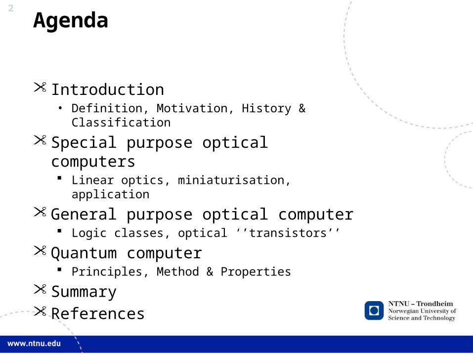
Agenda
Introduction• Definition, Motivation, History & Classification
Special purpose optical computers Linear optics, miniaturisation, application
General purpose optical computer Logic classes, optical ‘’transistors’’
Quantum computer Principles, Method & Properties
Summary References
3
INTRODUCTIONMotivation, Evolution & Classification
4
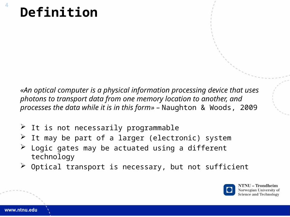
Definition
«An optical computer is a physical information processing device that uses photons to transport data from one memory location to another, and processes the data while it is in this form» – Naughton & Woods, 2009
It is not necessarily programmable It may be part of a larger (electronic) system Logic gates may be actuated using a different technology Optical transport is necessary, but not sufficient

5
Comparison optics/electronicsProperty Optical Electronic
Information signal Photon Electromagnetic pulse
Cross-talk None (free space) Yes
Electromagnetic interference
None Yes
Parallel processing Space & frequency in the same device
Space
Material & information signal coupling
Poor to moderate Excellent
Integrated circuits Research stage Mature
Gate size Limited by wavelength Quantum limit
Gate speed Milli- to Picoseconds Picoseconds
Fan in/out Poor to moderate Excellent
Heat dissipation Debated Bottleneck
6
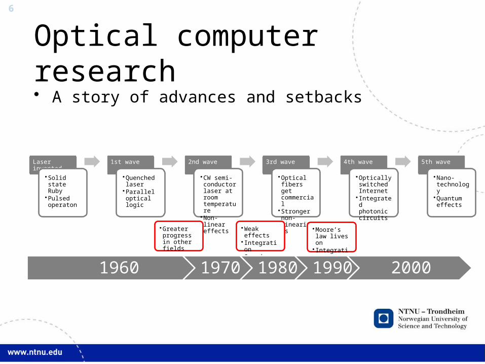
Optical computer research• A story of advances and setbacks
Laser invented
•Solid state Ruby
•Pulsed operaton
1st wave
•Quenched laser
•Parallel optical logic
2nd wave
•CW semi-conductor laser at room temperature
•Non-linear effects
3rd wave
•Optical fibers get commercial
•Stronger non-linearities
4th wave
•Optically switched Internet
• Integrated photonic circuits
5th wave
•Nano-technology
•Quantum effects
•Greater progress in other fields
•Weak effects• Integration•Speed
•Moore’s law lives on
• Integration
1960 1970 1980 1990 2000
7
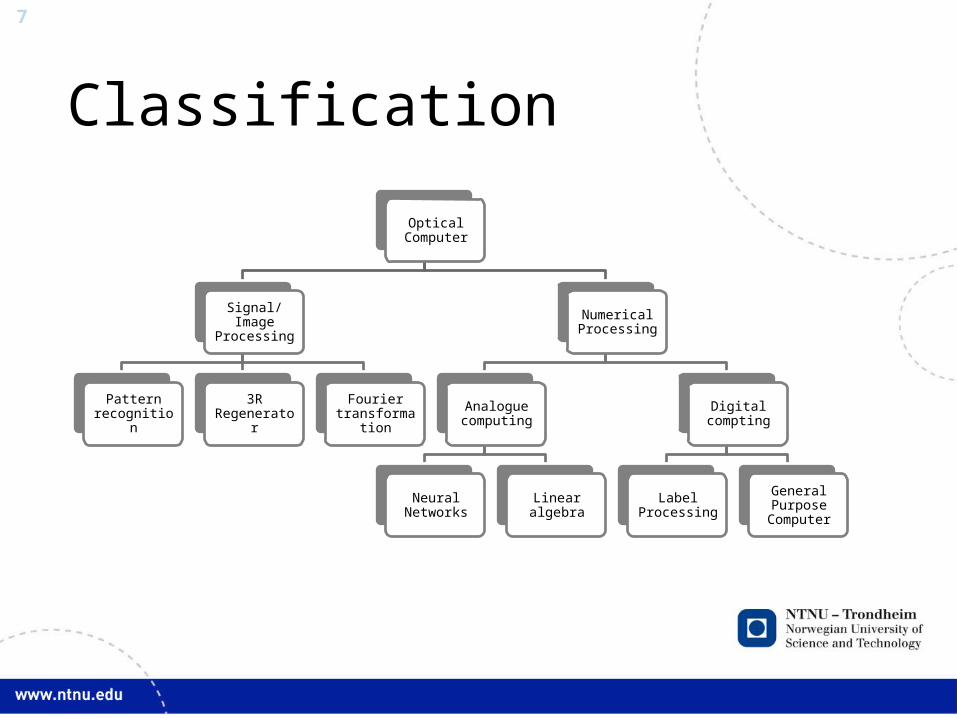
Classification
Optical Computer
Signal/Image Processing
Pattern recognition
3R Regenerator
Fourier transformation
Numerical Processing
Analogue computing
Neural Networks Linear algebra
Digital compting
Label Processing
General Purpose
Computer
8
SPECIAL PURPOSE COMPUTERS
Classic Linear Optics & Refinements

9
Using classic linear optics
• Perfect shuffle –permutes an analogue/digital address into any other adress in (logN)2 steps.
• Requires additional capability of exchanging nearest neigbours
• High spatial 3D paralellism
• Applications• All-optical label swapping• Image analysis (rotation)
Ref. & figure from Lohmann, 1985
10
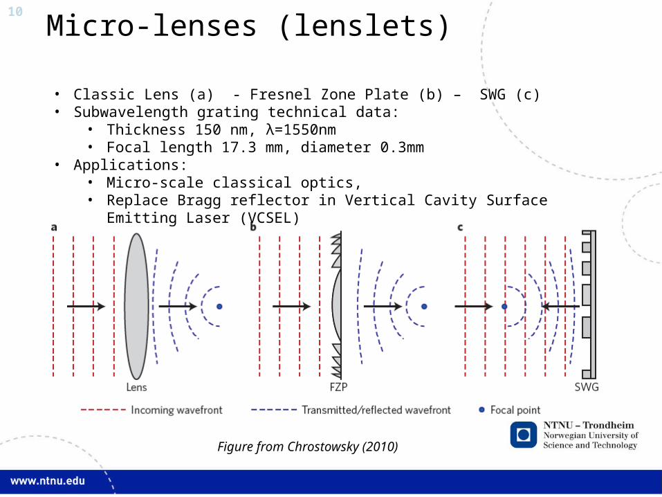
Micro-lenses (lenslets)
• Classic Lens (a) - Fresnel Zone Plate (b) – SWG (c)• Subwavelength grating technical data:
• Thickness 150 nm, λ=1550nm• Focal length 17.3 mm, diameter 0.3mm
• Applications: • Micro-scale classical optics, • Replace Bragg reflector in Vertical Cavity Surface Emitting Laser (VCSEL)
Figure from Chrostowsky (2010)
11
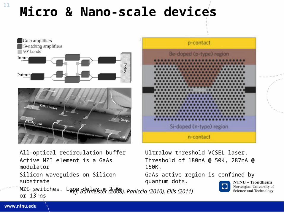
Micro & Nano-scale devices
Ultralow threshold VCSEL laser.
Threshold of 180nA @ 50K, 287nA @ 150K.
GaAs active region is confined by quantum dots.
All-optical recirculation buffer
Active MZI element is a GaAs modulator
Silicon waveguides on Silicon substrate
MZI switches. Loop delay = 2.6m or 13 ns
Ref: Burmeister (2008), Paniccia (2010), Ellis (2011)
12
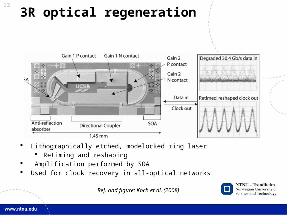
3R optical regeneration
Lithographically etched, modelocked ring laser Retiming and reshaping
Amplification performed by SOA Used for clock recovery in all-optical networks
Ref. and figure: Koch et al. (2008)
13
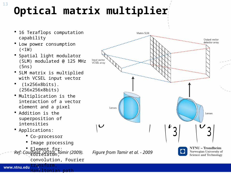
Optical matrix multiplier
(𝑎 𝑏 𝑐𝑑 𝑒 𝑓𝑔 h 𝑘) .(𝑖1𝑖2𝑖3)=(𝑜1𝑜2𝑜3)
16 Teraflops computation capability
Low power consumption (<1W) Spatial light modulator (SLM)
modulated @ 125 MHz (5ns) SLM matrix is multiplied with
VCSEL input vector (1x256x8bits).(256x256x8bits) Multiplication is the interaction of
a vector element and a pixel Addition is the superposition of
intensities Applications:
Co-processor Image processing Element for: correlaton,
convolution, Fourier transform, Hamiltonian path problem ++
Figure from Tamir et al. - 2009Ref: Caulfield (2010), Tamir (2009).

14
Versatility of matrix multiplier
General formGeneral form(analogue or digital)
Permutation, Spatial rotation & Shuffle
Addition & Logical OR
Multiplication & Logical AND
Notes: Binary OR requires boolean interpretation of addition output.
Binary AND uses the SLM matrix and input vector as inputs

15
GENERAL PURPOSEOPTICAL COMPUTER
Logic schemes & devices
16
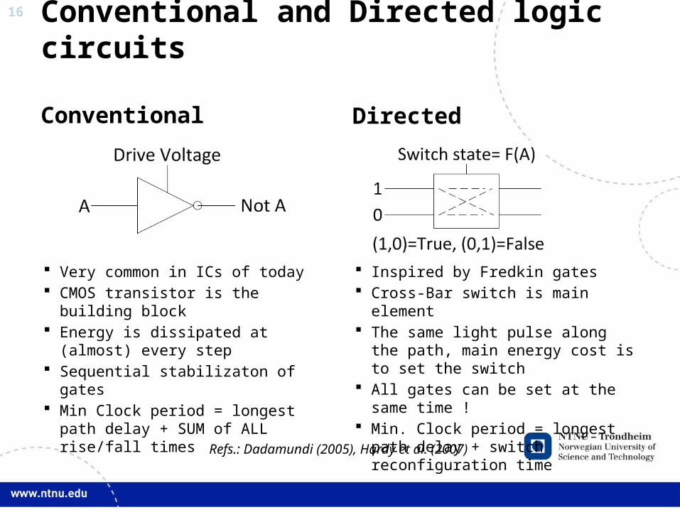
Conventional and Directed logic circuits
Conventional Directed
Refs.: Dadamundi (2005), Hardy et al. (2007)
Very common in ICs of today CMOS transistor is the building block Energy is dissipated at (almost) every
step Sequential stabilizaton of gates Min Clock period = longest path delay +
SUM of ALL rise/fall times
Inspired by Fredkin gates Cross-Bar switch is main element The same light pulse along the path,
main energy cost is to set the switch All gates can be set at the same time ! Min. Clock period = longest path delay
+ switch reconfiguration time
17
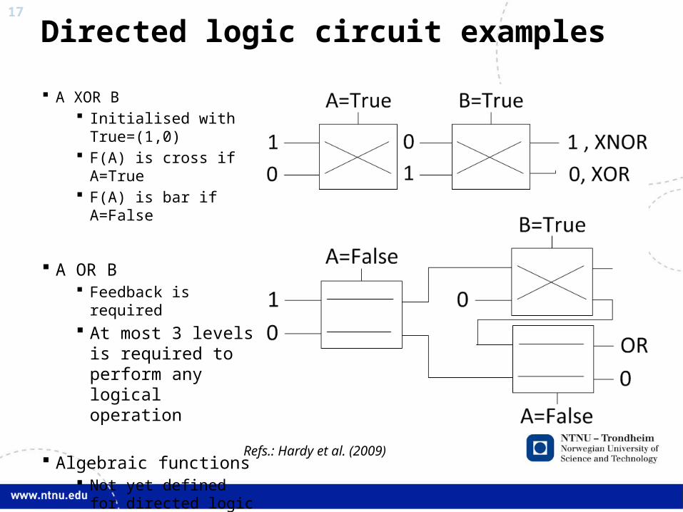
Directed logic circuit examples
Refs.: Hardy et al. (2009)
A XOR B Initialised with
True=(1,0) F(A) is cross if A=True F(A) is bar if A=False
A OR B Feedback is required At most 3 levels is
required to perform any logical operation
Algebraic functions Not yet defined for
directed logic Matrix operations ??
18
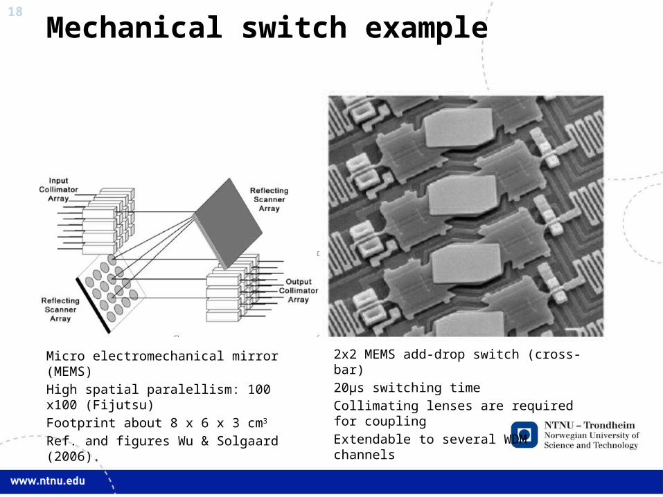
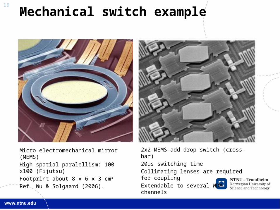
Mechanical switch example
2x2 MEMS add-drop switch (cross-bar)
20μs switching time
Collimating lenses are required for coupling
Extendable to several WDM channels
Micro electromechanical mirror (MEMS)
High spatial paralellism: 100 x100 (Fijutsu)
Footprint about 8 x 6 x 3 cm3
Ref. and figures Wu & Solgaard (2006).
19
Mechanical switch example
2x2 MEMS add-drop switch (cross-bar)
20μs switching time
Collimating lenses are required for coupling
Extendable to several WDM channels
Micro electromechanical mirror (MEMS)
High spatial paralellism: 100 x100 (Fijutsu)
Footprint about 8 x 6 x 3 cm3
Ref. Wu & Solgaard (2006).
20
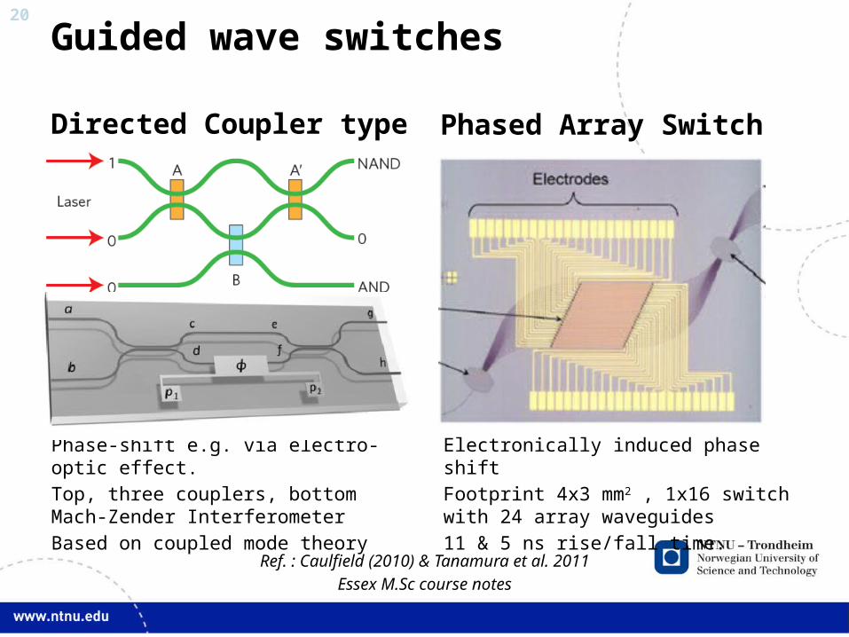
Guided wave switches
Directed Coupler type Phased Array Switch
Ref. : Caulfield (2010) & Tanamura et al. 2011
Essex M.Sc course notes
Phase-shift e.g. via electro-optic effect.
Top, three couplers, bottom Mach-Zender Interferometer
Based on coupled mode theory
Electronically induced phase shift
Footprint 4x3 mm2 , 1x16 switch with 24 array waveguides
11 & 5 ns rise/fall time.
21
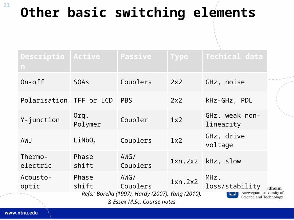
Other basic switching elements
Description Active Passive Type Techical data
On-off SOAs Couplers 2x2 GHz, noise
Polarisation TFF or LCD PBS 2x2 kHz-GHz, PDL
Y-junction Org. Polymer Coupler 1x2 GHz, weak non-linearity
AWJ LiNbO2 Couplers 1x2 GHz, drive voltage
Thermo-electric Phase shift AWG/Couplers 1xn,2x2 kHz, slow
Acousto-optic Phase shift AWG/Couplers 1xn,2x2 MHz, loss/stability
Refs.: Borella (1997), Hardy (2007), Yang (2010),
& Essex M.Sc. Course notes
22
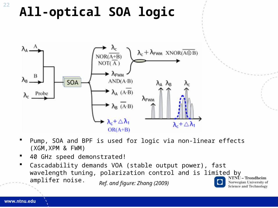
All-optical SOA logic
Pump, SOA and BPF is used for logic via non-linear effects (XGM,XPM & FWM) 40 GHz speed demonstrated! Cascadability demands VOA (stable output power), fast wavelength tuning,
polarization control and is limited by amplifer noise.
Ref. and figure: Zhang (2009)
23
QUANTUM COMPUTINGPrinciples & Advantages
24
Basic elements
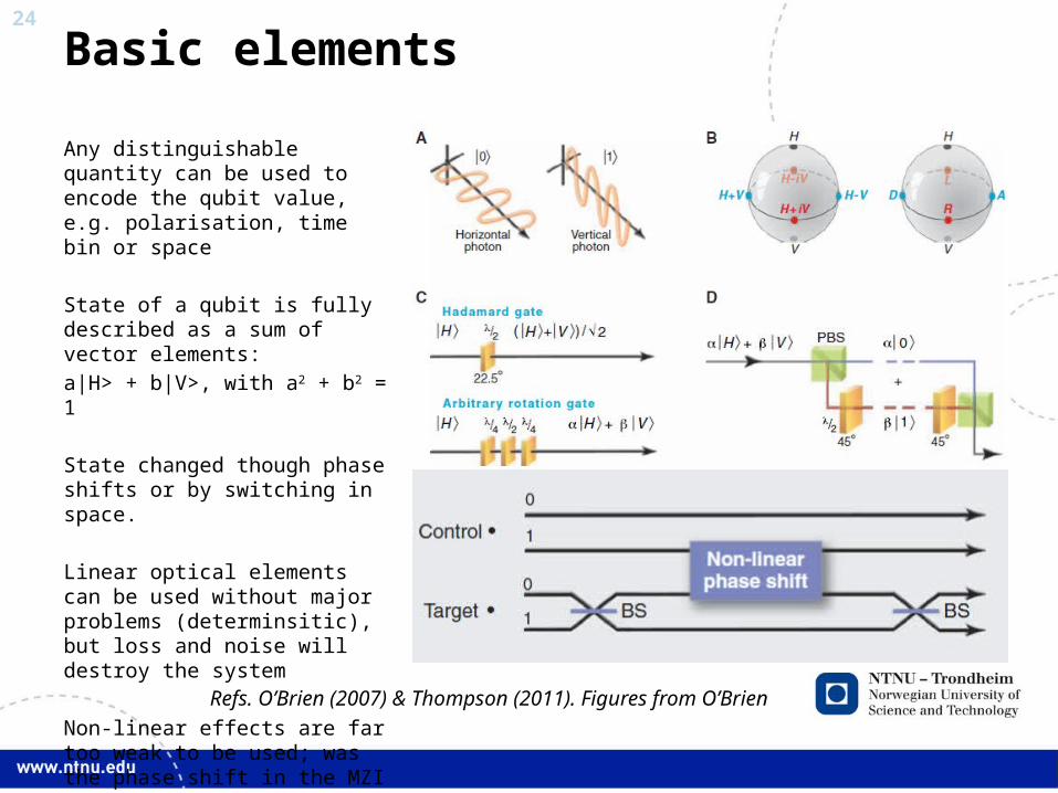
Any distinguishable quantity can be used to encode the qubit value, e.g. polarisation, time bin or space
State of a qubit is fully described as a sum of vector elements:
a|H> + b|V>, with a2 + b2 = 1
State changed though phase shifts or by switching in space.
Linear optical elements can be used without major problems (determinsitic), but loss and noise will destroy the system
Non-linear effects are far too weak to be used; was the phase shift in the MZI applied or not?
Refs. O’Brien (2007) & Thompson (2011). Figures from O’Brien
25
Entangled states
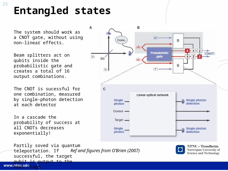
The system should work as a CNOT gate, without using non-linear effects.
Beam splitters act on qubits inside the probabilistic gate and creates a total of 16 output combinations.
The CNOT is sucessful for one combination, measured by single-photon detection at each detector
In a cascade the probability of success at all CNOTs decreases exponentially!
Partily soved via quantum teleportation. If successful, the target qubit is output to the next stage.
Ref and figures from O’Brien (2007)
26
Summary
• Paralellism is a key property for high performance optical computing• NP to P computational complexity• Reduces footprint
• Optical signal processing is useful for special purpose applications; e.g. for optical networking
• The general purpose computer should not be an optical blue-print of electronic systems
• Poor cascadability is currently the main impediment to general purpose optical computer
• Quantum effects enables small, power-efficient and computationally efficient algorithms, but a realization is far from immediate
27 Properties of a quantum computer
• Power efficient• Very compact (but not much smaller than other)• Spatial paralellism represents a speedup• Probabilistic overhead is compensated for by «quantum speed-
up». Ignoring overhead gives exponential speedup for some specific problems.
• Identify states that correspond to a certain problem is difficult• Known applications:
• Factorisation problem• Fourier transform• Probabilistic database search
28
References
1. Naughton, T. J. and D. Woods (2009). “Optical Computing”. Encyclopedia of Complexity and Systems Science. R. A. Meyers, Springer New York
2. Lohmann, A. W. (1986). "What classical optics can do for the digital optical computer." Appl. Opt. 25(10): 1543-1549
3. Abdeldayem, H., D. Frazier, et al. (2008). «Recent Advances in Photonic Devices for Optical Super Computing». Optical SuperComputing. S. Dolev, T. Haist and M. Oltean, Springer Berlin / Heidelberg.
4. Chrostowski, L. (2010). "Optical gratings: Nano-engineered lenses." Nat Photon 4(7): 413-415.
5. Dandamudi, S. (2005). Digital Logic Circuits. Guide to Assembly Language Programming in Linux, Springer US: 11-44
6. Ellis, B., M. A. Mayer, et al. (2011). "Ultralow-threshold electrically pumped quantum-dot photonic-crystal nanocavity laser." Nat Photon 5(5): 297-300
7. Tamir, D. E., N. T. Shaked, et al. (2008). Electro-Optical DSP of Tera Operations per Second and Beyond (Extended Abstract). Proceedings of the 1st international workshop on Optical SuperComputing. Vienna, Austria, Springer-Verlag: 56-69.
8. Hardy, J. and J. Shamir (2007). "Optics inspired logic architecture." Opt. Express 15(1): 150-165
9. Wu, M. C., O. Solgaard, et al. (2006). "Optical MEMS for Lightwave Communication." J. Lightwave Technol. 24(12): 4433-4454.
10. Caulfield, H. J. and S. Dolev (2010). "Why future supercomputing requires optics." Nat Photon 4(5): 261-263.
11. Borella, M. S., J. P. Jue, et al. (1997). "Optical components for WDM lightwave networks." Proceedings of the IEEE 85(8): 1274-1307.
12. Yang, W., Y. Liu, et al. (2010). "Wavelength-Tunable Erbium-Doped Fiber Ring Laser Employing an Acousto-Optic Filter." J. Lightwave Technol. 28(1): 118-122.
29
References II
13. Koch, B. R., A. W. Fang, et al. (2008). All-Optical Clock Recovery with Retiming and Reshaping Using a Silicon Evanescent Mode Locked Ring Laser. Optical Fiber communication/National Fiber Optic Engineers Conference
14. Paniccia, M., (2010), Integrating silicon photonics, Nature Photonics, Interview | Focus, Vol. 4.
15. Burmeister, E. F., J. Mack, et al. (2008). SOA Gate Array Recirculating Buffer for Optical Packet Switching, Optical Society of America
16. Zhang, X., J. Xu, et al. (2009). All-Optical Logic Gates Based on Semiconductor Optical Amplifiers and Tunable Filters. Optical SuperComputing. S. Dolev and M. Oltean, Springer Berlin / Heidelberg. 5882: 19-29.
17. Tucker, R. S. (2006). "The Role of Optics and Electronics in High-Capacity Routers." Lightwave Technology, Journal of 24(12): 4655-4673
18. Thompson, M. G., A. Politi, et al. (2011). "Integrated waveguide circuits for optical quantum computing." Circuits, Devices & Systems, IET 5(2): 94-102
19. O'Brien, J. L. (2007). "Optical Quantum Computing." Science 318(5856): 1567-1570
30
Optical label processing
• Klonidis et al. • Muligens 1 slide av Leuthold