Embed Size (px)
Citation preview

J
particular supply sources and loads - J1
1. protection of circuits supplied by an alternator
a major difficulty encountered whenan installation may be supplied fromalternative sources (e.g. a HV/LVtransformer or a LV generator) is theprovision of electrical protectionwhich operates satisfactorily oneither source. The crux of theproblem is the great difference in thesource impedances; that of thegenerator being much higher thanthat of the transformer, resulting in acorresponding difference in themagnitudes of fault currents.
Most industrial and large commercialelectrical installations include certainimportant loads for which a power supplymust be maintained, in the event that thepublic electricity supply fails:c either, because safety systems are involved(emergency lighting, automatic fire-protectionequipment, smoke dispersal fans, alarms andsignalization, and so on...) or:c because it concerns priority circuits, such
as certain equipment, the stoppage of whichwould entail a loss of production, or thedestruction of a machine tool, etc.One of the current means of maintaining asupply to the so-called “essential” loads, inthe event that other sources fail, is to install adiesel-generator set connected, via achangeover switch, to an emergency-powerstandby switchboard, from which theessential services are fed (figure J1-1).
G
standby supplychange-over switch
essential loadsnon essential loads
HV
LV
fig. J1-1: example of circuits supplied from a transformer or from an alternator.
1.1 an alternator on short-circuitthe establishment of short-circuitcurrent (fig. J1-2)Apart from the limited magnitude of faultcurrent from a standby alternator, a furtherdifficulty (from the electrical-protection pointof view) is that during the period in whichLV circuit breakers are normally intended tooperate, the value of short-circuit currentchanges drastically.For example, on the occurrence of a short-circuit at the three phase terminals of analternator, the r.m.s. value of current willimmediately rise to a value of 3 In to 5 In*.An interval of 10 ms to 20 ms following theinstant of short-circuit is referred to as the“sub-transient” period, in which the currentdecreases rapidly from its initial value. Thecurrent continues to decrease during theensuing “transient” interval which may last for80 ms to 280 ms depending on the machinetype, size, etc. The overall phenomenon isreferred to as the “a.c. decrement”. Thecurrent will finally stabilize in about
0.5 seconds, or more, at a value whichdepends mainly on the type of excitationsystem, viz:c manual;c automatic(see figure J1-2).Almost all modern generator sets haveautomatic voltage regulators, compounded tomaintain the terminal voltage sensiblyconstant, by overcoming the synchronousimpedance of the machine as reactive currentdemand changes.This results in an increase in the level of faultcurrent during the transient period to give asteady fault current in the order of 2.5 In to4 In* (figure J1-2).In the (rare) case of manual control of theexcitation, the synchronous impedance of themachine will reduce the short-circuit currentto a value which can be as low as 0.3 In, butis often close to In*.
r.m.s.
0.3 In
3 In
In
subtransientperiod
transientperiod
instantof fault
10 to20 ms
0.1 to0.3 s
alternatorwith automaticvoltage regulator
alternatorwith manualexcitation control
t
fig. J1-2: establishment of short-circuit current for a three-phase short circuit at theterminals of an alternator.* depending on the characteristics of the particular machine.

J
J2 - particular supply sources and loads
1. protection of circuits supplied by an alternator (continued)
1.1 an alternator on short-circuit (continued)
Figure J1-2 shows the r.m.s. values ofcurrent, on the assumption that no d.c.transient components exist. In practice, d.c.components of current are always present tosome degree in at least two phases, beingmaximum when the short-circuit occurs at thealternator terminals.This feature would appear to complicate stillfurther the matter of electrical protection, but,in fact, the d.c. component in each phasesimply increases the r.m.s. values alreadymentioned, so that calculations and tripping-current settings for protective devices basedonly on the a.c. components, as indicatedbelow, will be conservative, i.e. the actualcurrents will always be either equal to orhigher than those calculated.The further the point of short-circuit from thegenerator the lower the fault current, and themore rapidly the transient d.c. componentsdisappear. Furthermore, the a.c. decrementalso becomes negligible when the networkimpedance to the fault position attains ohmicvalues which are high compared with thereactance values of the alternator (since theoverall change in impedance is then relativelysmall).
alternator impedance dataManufacturers furnish values of the severalimpedances mentioned below. Resistancesare negligibly small compared to thereactances.It can be seen from the constantly-changingvalue of r.m.s. current that the effectivereactance* changes constantly from a lowvalue (sub-transient reactance) to a highvalue (synchronous reactance) in a smoothprogression.The values discussed below are derived fromtest curves and correspond with currentvalues measured at the instant of short-circuit.* An explanation of the significance of thefixed reactance values and how they relate toa smooth variation of current is brieflydescribed in Appendix J1.c the sub-transient reactance x”d isexpressed in % by the manufacturer(analogous to the short-circuit impedancevoltage of a transformer). The ohmic valueX”d is therefore calculated as follows:
X”d (ohms) = x”d Un2 10-5
Pnwhere:x”d is in %Un is in volts (phase/phase)Pn is in kVAc the % transient reactance x’d is given inohms by:
X'd (ohms) = x'd Un2 10-5
Pnc the % zero-phase-sequence reactance x’ois given in ohms by:
X'o (ohms) = x'o Un2 10-5
PnIn the absence of more precise information,the following representative values may beused:x”d = 20% ; x’d = 30 % ; x’o = 6%Pn and Un being, respectively, the rated3-phase power (kVA) and the ratedphase/phase voltage of the alternator (volts).
The sub-transient reactance is used whencalculating the short-circuit current-breakingrating for LV circuit breakers which haveopening times of 20 ms or less, and also forthe electrodynamic stresses to be withstoodby CBs and other components (such asbusbars, cleated single-core cables, etc.).The transient reactance is used whenconsidering the breaking capacity of LV circuitbreakers with an opening time that exceeds20 ms, and also for the thermal withstandcapabilities of switchgear and other systemcomponents.
Remark: from the instant at which the short-circuit is established, the alternator reactancewill rapidly increase. This means that thecurrents calculated from the defined fixedvalues x"d and x'd (for breaking capacity) willalways exceed those that will actually occurat the instant of circuit breaker contactseparation, i.e. there is an inherent safetyfactor incorporated in the current-levelcalculation.These calculations for the circuit breakershort-circuit breaking capacity are based onthe symmetrical a.c. components of currentonly, i.e. no account is taken of the d.c.unidirectional components.For the circuit breaker short-circuit makingcapacity, the d.c. components are crucial, asdiscussed in Chapter C, Sub-clause 1.1(figure C-5).

J
particular supply sources and loads - J3
short-circuit current magnitudeat the terminals of an alternatorc the transient 3-phase short-circuit currentat the terminals of an alternator is given by:
Isc = Ig 100* where: x’dIg: rated full-load current of the alternatorx’d = transient reactance per phase of thealternator in %;c when these values are compared withthose for a short-circuit at the LV terminals of
a transformer of equal kVA rating, the currentfrom the alternator will be found to be of theorder of 5 or 6 times less than that from thetransformer. The difference will be evengreater where (as is generally the case) thealternator rating is lower than that of thetransformer.* for CBs with opening time exceeding 20 ms.
non essential loads
630 kVA20 kV/400 VUsc = 4%
A
250 kVA400 VX'd = 30%
essential loads
fig. J1-3: example of an essential services switchboard supplied (in an emergency) from astandby alternator.
Example (figure J1 - 3)What is the value of 3-phase short-circuitcurrent at point A according to the origin ofsupply?Circuit impedances are negligible comparedwith those of the sources.c transformer supply3-phase Isc = 21.5 kA(see table C20 in Chapter C)
c alternator supply
3-phase Isc = Ig x 100 = Pn x 100 x'd eUn x'dwhere: Pn is expressed in kVA
Un is expressed in voltsx’d is expressed in %Isc is expressed in kA
3-phase Isc = 250 x 100 = 1.2 kA ex 400 x 30

J
J4 - particular supply sources and loads
1. protection of circuits supplied by an alternator (continued)
1.2 protection of essential services circuits supplied in emergencies from an alternator
the difficulty is due to the smallmargin between the rated currentand the short-circuit current of thealternator.
The characteristics (s.c. breaking capacityand range of adjustable magnetic trippingunit) of the CBs protecting the circuits ofessential loads must be defined as describedbelow:
Choice of s.c. breaking capacityThis parameter must always be calculated forthe condition of supply from the transformer,or other “normal” source.
Adjustment of magnetic tripping unitsIn practice, the only circuit breakersconcerned are those protecting the essentialservices circuits at the main generaldistribution board.The protection of circuits from localdistribution or sub-distribution boards isalways calibrated at a much lower level thanthose at the main general distribution board,so that, except in unusual cases, adequatefault currents are available from an alternatorto ensure satisfactory protective-gearoperation at these lower levels.Two difficulties have to be overcome:c the first is the need for discrimination ofcircuit protection with the protection schemefor the alternator.For the basic protection requirements of analternator, viz: overload protection, the curveshown in figure J1-4 is representative (seeNote 1).c the second concerns protection of personsagainst electric shock from indirect contact,when the protection depends on theoperation of overcurrent relays (for example,in IT* or TN systems). The operation of theserelays must be assured, whether the supplyis from the alternator or from the transformer(see Note 2).Instantaneous or short-time delay magnetic-relay trip settings of the circuit breakersconcerned must therefore be set to operateat minimum fault levels occurring at theextremity of the circuits they protect, whenbeing supplied from the alternator.
Note 1. Sensitive high-speed protection of analternator against internal faults (i.e.upstream of its CB) is always possible byusing a pilot-wire and current-transformersdifferential scheme of protection, with theadvantage that discrimination with circuitprotection schemes is absolute. The problemof discriminative overload protection (asnoted above) remains, however.A widely-used solution to this problem isprovided by a voltage-controlled overcurrentrelay, which depends on the followingprinciple: short-circuit currents cause muchlower system voltages than overloadcurrents. An inverse-time/current overloadrelay is used having two operating curves,one of which corresponds to that of fig. J1-4,and is effective when system voltage levelsare normal.If the system voltage falls below a pre-setvalue, the relay is automatically switched tooperate much faster and at lower currentlevels than those shown in fig. J1-4.Modern low-setting magnetic tripping units,however, often provide a simpler solution asnoted in 1.3 below.Note 2. Where the level of earth-fault currentis not sufficient, in IT* and TN systems, to tripCBs on overcurrent, the protection againstindirect-contact hazards can be provided byan appropriate use of RCDs, as indicated inChapter G Sub-clause 6.5 Suggestion 2 (forIT circuits) and Sub-clause 5.5. Suggestion 2(for TN circuits).
time (s)
1
32
1.1overload
71012
100
1000
1.2 1.5 2 3 4 5 I/IG
fig. J1-4: overload protection of analternator.
* Two concurrent earth faults on different phases or on one phase and on a neutral conductor, are necessary on IT systems, tocreate an indirect-contact hazard.

J
particular supply sources and loads - J5
1.3 choice of tripping units
the calculation of the minimum faultcurrent (in IT or TN schemes) iscomplex. Software packages for thispurpose are available.
calculation of the fault-currentloop impedance (Zs) for IT andTN systemsThe determination of the minimum level ofshort-circuit current, from the calculation ofthe fault-loop impedance Zs (by the sum ofimpedances method) is difficult, mainlybecause of the uncertainly, in a practicalinstallation, of the accuracy of the zero-phase-sequence impedances. Whenconductor routes are known in sufficientdetail, impedances can then be determinedby the use of software, currently availablecommercially. Approximate methods for3-phase and 1-phase short circuits arepresented in Sub-clause 1.4.
types of suitable tripping unitsThe choice of low-setting magnetic trippingunits will generally be necessary, such asCompact NS* with STR (magnetic-trip shorttime delay is adjustable from 1.5 to 10 Ir) orcircuit breakers Multi 9* curve B (trippingbetween 3 and 5 In).In practice, these CBs (or their equivalents)will always be necessary when the currentrating of the CB is greater than one third ofthe alternator current rating and will, in mostcases, obviate the need for voltage-controlledoverload relays.Switchgear manufacturers often furnishtables showing recommended combinationsof circuit breakers for commonly-usedstandby-generator schemes.* Merlin Gerin products.
characteristics of protectionfor essential-services circuitstype of circuit fault-breaking rating tripping unit adjustment
(FBR)
main FBR > Isc Im or short-delay trip settingcircuits with supply level < the minimum
from transformer fault current at the far endof the circuit when suppliedfrom the alternator(see Note 2 in Sub-clause 1.2)
sub- FBR > Isc check the protectionand final with supply of persons againstcircuits from transformer indirect-contact hazards,
particularly on IT and TNsystems (see Note 2in Sub-clause 1.2)
Isc: 3-ph short-circuit currentIm: magnetic-tripping-relay current setting
loads
B
diesel-generatorprotectioncabinet
power-sourcechangeover switch
fig. J1-5: the protection of essential services circuits.
J
J6 - particular supply sources and loads
1. protection of circuits supplied by an alternator (continued)
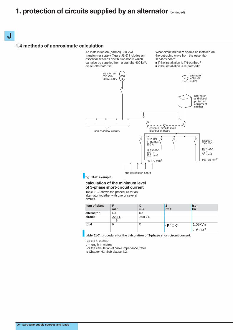
1.4 methods of approximate calculationAn installation on (normal) 630 kVAtransformer supply (figure J1-6) includes anessential-services distribution board whichcan also be supplied from a standby 400 kVAdiesel-alternator set.
What circuit breakers should be installed onthe out-going ways from the essential-services board:c if the installation is TN-earthed?c if the installation is IT-earthed?
sub-distribution board
NS160NTM400D
IB = 92 A70 m35 mm2
PE : 35 mm2
alternatorand dieselprotectionequipmentcabinet
transformer630 kVA20 kV/400 V
alternator400 kVA400 V
NS250NSTR22SE250 A
IB = 220 A100 m120 mm2
PE : 70 mm2
PE
non essential circuitsessential circuits maindistribution board
fig. J1-6: example.
calculation of the minimum levelof 3-phase short-circuit currentTable J1-7 shows the procedure for analternator together with one or severalcircuits.
item of plant R X Z IscmΩ mΩ mΩ kA
alternator Ra X'dcircuit 22.5 L 0.08 x L
Stotal R X R X2 2+ 1.05xVn
R X2 2+table J1-7: procedure for the calculation of 3-phase short-circuit current.
S = c.s.a. in mm2
L = length in metresFor the calculation of cable impedance, referto Chapter H1, Sub-clause 4.2.

J
particular supply sources and loads - J7
Consider the 220 A circuit in figure J1-6c alternatorRa = 0
X’d = Un2 x 0.30 = 4002 x 0.30 = 120 mΩ Pn 400c circuit
Rc = 22.5 x 100 = 18.75 mΩ 120Xc = 0.08 x 100 = 8 mΩc application of the method of impedances asindicated in table J1-7;R = Ra + Rc = 0 + 18.75 = 18.75 mΩX = X’d + Xc = 120 + 8 = 128 mΩtotal impedance per phase:
Isc = 1.05 Vn = 1.05 x 230 = 1.87 kA (r.m.s.) Z 0.129
Note: In practice there will always be somemeasure of d.c. transient current in at leasttwo phases, so that the above value willnormally be exceeded during the periodrequired to trip the CB.
Z R X (18.75) (128) 129.4 m2 2 2 2= + = + = Ω
calculation of the minimum levelof 1-phase to earth short-circuitfault currentTable J1-8 shows the procedure for analternator together with one or severalcircuits.
item of plant R X Z IscmΩ mΩ mΩ kA
alternator Ra 2 X'd + Xo 3
circuit 22.5 L (1 + m) 0.08 x L x 2 Sph
total R X R X2 2+ 1.05xVn
R X2 2+table J1-8: procedure for the calculation of 1-phase to neutral short-circuit current.
For the calculation of cable impedance, referto Chapter H1, Sub-clause 4.2.
Consider the 220 A circuit in figure J1-6c alternatorRa = 0
Xa = (2 x 120 + 4002 x 0.06) x 1 = 88 mΩ 400 3c circuit
Rc = 22.5 x 100 x (1 + 120 / 70) = 50.89 mΩ 120Xc = 0.08 x 100 x 2 = 16 mΩc application of the method of impedances,as for the previous example:R = Ra + Rc = 0 + 50.89 = 50.89 mΩX = Xa + Xc = 88 + 16 = 104 mΩThe total impedance:
and Isc1 (phase/neutral) = 1.05 x 230 = 2.09 kA. 115.8
Z R X 50.89 104 115.8 m2 2 2 2= + = + = Ω

J
J8 - particular supply sources and loads
1. protection of circuits supplied by an alternator (continued)
1.4 methods of approximate calculation (continued)
maximum permissible settingof instantaneous or short-timedelay tripping unitsc TN schemeOf the two fault conditions considered(3-phase and 1-phase/neutral) the 3-phasefault was found to give the lower short-circuitcurrent. The setting of the protective relaymust therefore be selected to a current levelbelow that calculated.For the 220 A outgoing circuit the trip unitwould be rated at 250 A and adjusted (inprinciple) to Isc/250, i.e. 1,870/250 = 7.4 In.Owing to a ± 20 % manufacturing tolerancehowever, the maximum permissible setting
would be 7.4 = 6.2 In 1.2A tripping unit type TM250D* set at 6 In on aNS250N* circuit breaker (breaking capacity= 36 kA i.e. > 21.5 kA) would be appropriate;c IT schemeIn this case the protection must operate for asecond earth fault occurring before the firstearth fault is cleared. This condition (only)produces indirect-contact hazards on an ITsystem.If the neutral conductor is not distributed, thenthe minimum short-circuit current for thesystem will be the phase-to-phase value(i.e. concurrent earth faults on two differentphases) which is equal to 0.866 Isc(Isc = the 3-phase s.c. current).If the neutral is distributed, the minimum s.c.current occurs when a phase-to-earth faultand a neutral-to-earth fault occurconcurrently, and a protective relay settingequal to 0.5 Isc (phase to neutral) i.e. half thevalue of a phase-to-neutral short-circuitcurrent, is conventionally used to ensurepositive relay operation,v for the case of a non-distributed neutral,the minimum s.c. current =0.5 x 0.866 x 1.87 = 0.81 kAThe tripping unit rated at 250 A will be set at810 x 1 = 2.7 In250 1.2(the factor 1.2 accounting for the ± 20 %manufacturing tolerance for tripping units).A TM250D or a STR22SE tripping unit set at2.5 In would be appropriate,v when the neutral is distributed, theminimum s.c. current relay setting= 0.5 x 2.08 = 1.04 kAThe 250 A tripping unit will be set at1.040 x 1 250 1.2= 3.5 In (the 1.2 factor coveringmanufacturing tolerance, as before)A STR22SE tripping unit, set at 3.0 In wouldbe satisfactory.Note: The foregoing method is based on asimplified application of the followingformulae:➀
Isc (3-phase) = V ph Z1➁
Isc (phase/phase) = eVph Z1+Z2
➂
Isc (phase/earth) = 3 Vph Z1+Z2+Z0
WhereZ1 = positive phase-sequence impedanceZ2 = negative phase-sequence impedanceZ0 = zero phase-sequence impedance
Simplifications:c Z1 is assumed to be equal to Z2 so thatformula ➁ becomeseVph = 0.866 Vph or 0.866 Isc (3-phase) 2 Z1 Z1
c In table J1-8 the calculated cable reactanceassumes that X1 = X2 = X0 for the cable, sothat in formula ③ the total reactance= (X1 + X2 + X0) 1/3 = (3 X1) 1/3 = X1
* Merlin Gerin product.
J
particular supply sources and loads - J9
1.5 the protection of standby and mobile a.c. generating setsPractical guides in certain national standardsclassify generator sets according to threecategories, viz:c permanent installations (as discussed inSub-clauses 1.1 to 1.4);c mobile sets (figure J1-9);c portable power packs (figure J1-10).
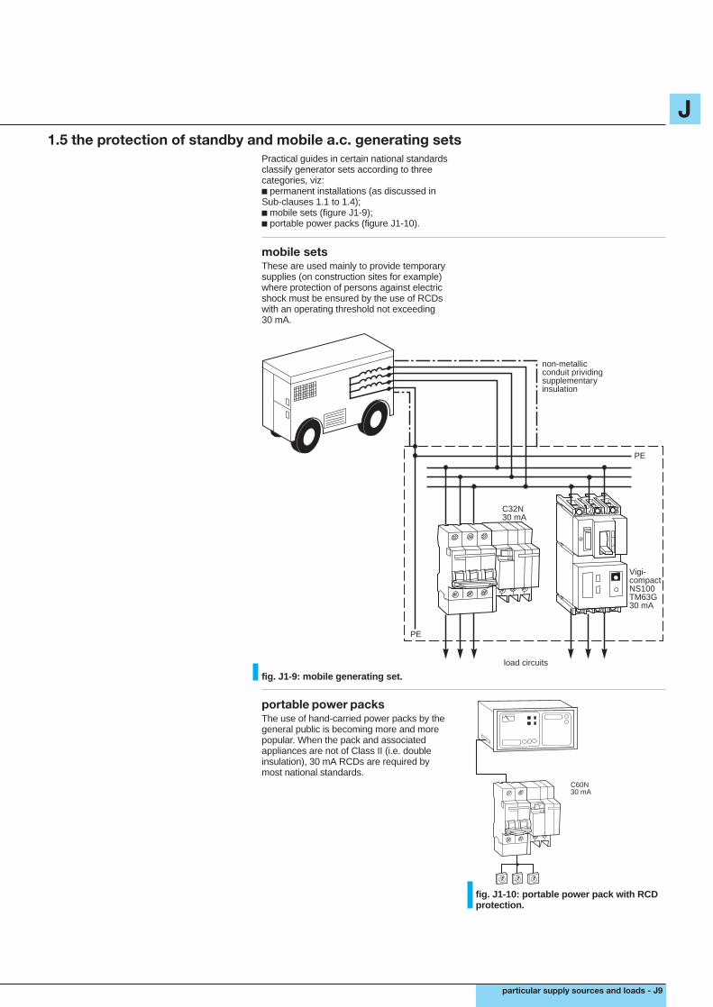
mobile setsThese are used mainly to provide temporarysupplies (on construction sites for example)where protection of persons against electricshock must be ensured by the use of RCDswith an operating threshold not exceeding30 mA.
Vigi-compactNS100TM63G30 mA
C32N30 mA
PE
load circuits
non-metallicconduit prividingsupplementaryinsulation
T
PE
fig. J1-9: mobile generating set.
portable power packsThe use of hand-carried power packs by thegeneral public is becoming more and morepopular. When the pack and associatedappliances are not of Class II (i.e. doubleinsulation), 30 mA RCDs are required bymost national standards.
C60N30 mA
T
fig. J1-10: portable power pack with RCDprotection.

J
J10 - particular supply sources and loads
2. inverters and UPS (Uninterruptible Power Supply units)
2.1 what is an inverter?An inverter produces an a.c. supply of highquality (i.e. an undistorted sine-wave, freefrom interference) from a d.c. source; itsfunction is the inverse of that of a rectifier(figure J2-1).Its main purpose (when associated with arectifier which provides its input) is to afford ahigh-quality power supply to equipment forwhich the interference and disturbances of anormal power-supply system cannot betolerated (e.g. to computer systems).Power systems are subjected to many kindsof perturbation which adversely affect thequality of supply: atmospheric phenomena(lightning, freezing), accidental faults (short-circuits), industrial parasites, the switching oflarge electric motors (lifts, fluorescent lighting)are among the many causes of poor qualityof supplies.Apart from occasional loss of supply, thedisturbances take the form of more-or-lesssevere voltage dips, high- and low-frequencyparasites, continuous “noise” from
fluorescent-lamp circuits and (normallyundetectable, but totally unacceptable tosensitive electronic systems) of mini-interruptions of several milli-seconds.By the addition of a storage battery at theinput terminals of the inverter (and thereforeacross the output terminals of the associatedrectifier), an elementary UPS system isformed.In normal circumstances, the rectifier suppliesthe load through the inverter, while, at thesame time, a trickle charge from the rectifiermaintains the battery fully charged.A loss of a.c. power supply from thedistribution network would simply result in thebattery automatically maintaining the outputfrom the inverter with no discernableinterruption.
inverter
d.c. source load
sinusoidala.c. output
fig. J2-1: inverter function.
2.2 types of UPS system
there are two main types of UPSsystem:c off-line,c on-line.
Several types of UPS system exist accordingto the degree of protection against power-network “pollution” required, and whethersupply autonomy (automatic standby-supplyon the loss of normal power supply) isspecified, or not. The two most commonly-used types are described below.
An off-line type of UPS system (figure J2-2)is connected in parallel with a supply directfrom the public distribution network, as shownin figure J2-2, and is autonomous, within thecapacity of its battery, on loss of the a.c.power supply. In normal operation the filterimproves the quality of the current while thevoltage is maintained sensibly constant at itsdeclared value by appropriate and automaticregulation within the filter unit.When the tolerance limits are exceeded,including a total loss of supply, a contactor,which carries the normal load, changes overrapidly to the UPS unit (in less than 10 ms)the power then being supplied from thebattery. On the return of normal power supply,the contactor changes back to its originalcondition; the battery then recharges to its fullcapacity.These units are normally of low rating(i 3 kVA) but are capable of passing large
transient currents such as those for motor-starting and switching on of (cold) resistiveloads. The most common use for such unitsis the supply to multi-workstation ITE(information technology equipment)installations, such as cash registers.
sensitiveload
a. c. power supplynetwork
rectifier/charger
battery
inverter filter
F
fig. J2-2: off-line UPS system.
An on-line type of UPS system (figure J2-3)is connected directly between the public a.c.supply network and the load, and has anautonomous capability, the period of whichdepends on the battery capacity and loadmagnitude.The total load passes through the system,which affords a supply of electrical energywithin strict tolerance limits, regardless of thestate of the a.c. power supply network.On loss of the latter, the battery automatically,and without interruption, maintains thepollution-free a.c. supply to the load.This system is equally suitable for small loads(i 3 kVA) or large loads (up to several MVA).
sensitiveload
a.c. power supplynetwork
rectifiercharger
battery
inverter
fig. J2-3: on-line UPS system.

J
particular supply sources and loads - J11
types of UPS units, filter plug mains-supply slim-line off-line on-lineconditioners and filters conditioner UPS UPS UPSdiagrams of principle
disturbances consideredtype of network correctivedisturbance measuresHF parasites c c c c cvariations of voltage regulation c c c cautonomy10 to 30 mn (according to battery capacity) c c crated poweri 250 VA c c c c c300 - 1,000 VA c c c c1,000 - 2,500 VA c c c> 2,500 VA c capplications
minimal all micro- micro-informatic highly disturbed a.c.protection sensitive informatic terminals power systems and/or
loads stand-alone PC heavy loads
Other apparatus, not assuring a no-breakperformance, but which protect sensitiveloads from certain disturbances commonlyoccurring on power distribution network,include the following:c the filter-plug which is simply an a.c. plugfor connecting or interconnecting loads, whichhas built-in HF (high-frequency) filters, inorder to reduce HF parasitic interference toacceptable levels. Its principal use is onmicro-informatic stand-alone PCs rated at250 to 1,000 VA, for general office purposes;c the network (or mains) -supply conditioneris a complete system for providing anuncontaminated a.c. power supply, butwithout autonomy, i.e. no provision againstloss of supply from the a.c. distributionnetwork.Its principal functions are to:v filter out HF parasites,v maintain a sensibly-constant voltage level,v isolate (galvanically) the load from the a.c.power network.It is equally applicable to office or industrialsystems which do not require a no-breakstandby supply, up to ratings of 5,000 VA;c the slim-line UPS has integral protectionwith autonomy for each micro-informaticstand-alone PC and its peripherals, and isinstalled immediately under the micro-processor. Two outputs, each with back-upfrom the UPS unit, supply the centralprocessor and screen. Two further outputs,which are filtered, supply other less-sensitiveunits (e.g. the printer). The slim-line UPSbelongs to the class of off-line UPS schemes.
F
F
table J2-4: examples of different possibilities and applications of inverters, in decontamination of supplies and in UPS scheme s.
2.3 standardsThe international standard presently coveringsemi-conductor converters is IEC 146-4.

J
J12 - particular supply sources and loads
2. inverters and UPS (Uninterruptible Power Supply units) (continued)
2.4 choice of a UPS systemThe choice of a UPS system is determinedmainly by the following parameters:c rated power, based on:v maximum value of actual estimated kVAdemand,v transitory current peaks (motor starting,energization of resistive loads,transformers...).Note: in order to obtain satisfactorydiscrimination of protective devices for all
types of load, it may be necessary to adjustthe power rating of the UPS system.c voltage levels upstream (input) anddownstream (output) of the UPS unit;c duration of autonomy required (i.e. supplyfrom the battery);c frequencies upstream (input) anddownstream (output) of the UPS unit;c level of availability required.
mains 1
(5) distribution board
(1)(2)
mains 2C/S
(4)
(3) (7)
(6)
UPS
(9)
(8)
fig. J2-5: classical arrangement of a UPS on-line installation, using an inverter.
UPS 1. inverter2. rectifier/charger3. batteries (usual periods of autonomy 10 - 15 - 30 mn - several hours)4. static contactor (see “availability” below)5. isolating transformer, if galvanic isolation from upstream circuits is necessary.6. outgoing ways7. transformer for specific downstream-circuits voltage8. changeover switch9. transformer to match the upstream voltage to that of the consumer.
Note: At first sight, the circuit arrangement infigure J2-5 closely resembles that of theoff-line UPS system (of figure J2-2). In fact,however, it is an on-line system, in which theload is normally passing through circuit 1.The static contactor is open in this situation,but closes automatically if the UPS systembecomes overloaded, or fails for any reason.In such a case, the load will then be suppliedfrom the (reserve) circuit 2. This action is theconverse of that of the off-line scheme.
Conditions will automatically return to normalif the overload, etc. is corrected.
In this arrangement, the voltage output ofthe inverter is always maintained insynchronism with the voltage of the power-supply network (i.e. within close tolerancelimits of magnitude and phase difference)thereby minimizing the disturbance in theevent of “instantaneous” changeover fromcircuit 1 to circuit 2 operation.
power (VA)The rated power of the UPS unit must besufficient to satisfy the steady load demandas well as loads of a transitory nature. Thedemand will be the sum of the apparent (VA)loads of individual items, for example, theCPU (central processing unit) and willamount to Pa, generally corrected by afactor (1.2 to 2) to allow for futureextensions.However, in order to avoid oversizing of theinstallation, account should be taken of theoverload capacity of the UPS components.For example, inverters manufactured byMerlin Gerin can safely withstand thefollowing overloaded condition:c 1.5 In for 1 minute;c 1.25 In for 10 minutes.
the power rating of a UPS unit musttake account of the peak motor-starting currents, of the possibility offuture extensions to the installation,and of the overload capability of theinverter and other UPS-unitcomponents.
Instantaneous variations of load:these variations occur at times of energizingand de-energizing of one or more items ofload. For an instantaneous change of load upto 100 % of the nominal rating of the UPSunit, the output voltage generally remainsbetween + 10 % and - 8 % of its rated value.

J
particular supply sources and loads - J13
Example of a power calculationChoice of a UPS unit suitable for the loadsshown in figure J2-6.
load circuits no.:
1 : 80 kVA
2 : 10 kVA
3 : 20 kVA
4 : 20 kVA
5 : 30 kVA
fig. J2-6: example.
Assumed operating constraints:circuit no. 4 will take a transitory current equalto 4 In for a period of 200 ms when initiallyenergized. This operation will be carried outat least once a day. The peak kVA demand,therefore, represents a supplement (over thesteady-state 20 kVA demand) of 3 x 20 kVA =60 kVA.The remaining circuits require no suchtransitory peak currents. In all cases the kVAvalues cited have taken the load powerfactors into account. Possible futureextensions to the installation are estimated toamount to 20% of the existing load.The maximum steady-state power demandpresently considered is therefore:P = 80 + 10 + 20 + 20 + 30 = 160 kVA.With allowance for extensions (of 20%)= 160 x 1.2 = 192 kVA.With an additional 200 ms peak of (3 x 20)kVA the total amounts to 192 + 60 = 252 kVA.The total of 252 kVA however, includes the60 kVA peak current which is easily absorbedby the 1.5 In overload capability of (a M.G)UPS system, so that the rating of a suitableUPS unit would be 252 x 1/1.5 = 168 kVAfor the nearest standard rating availableabove the calculated value, e.g. 200 kVA.For the choice of suitable protective devices,see Sub-clause 2.9. fig. J2-7: solution to the example.
200 kVA
C/S
availabilityA UPS system is generally provided with analternative (unconditioned) emergencysource, a situation which affords a relativelyhigh level of availability.By way of example, a UPS alone has aMTBF (mean time between failures) of50,000 hours.In the usual case, where the supply isdoubled as noted above (mains 1 andmains 2 in figure J2-5) the MTBF obtained isin the range 70,000 to 200,000 hours,depending on the availability of the secondsource.Switching from one source to the other isachieved automatically by a static (solidstate) contactor.Configurations having a higher redundancy,e.g. three UPS units each rated at P/2 tosupply a load of P (figure J2-8) are alsosometimes installed. The calculation of theirlevel of availability can be carried out byspecialists, and the manufacturers are able toquote availability levels, relative to their ownproducts and recommended layouts.
fig. J2-8: 3 UPS P/2 units providing a highlevel of availability of a power rated P.
C/S
P/2
P
P/2
P/2

J
J14 - particular supply sources and loads
2. inverters and UPS (Uninterruptible Power Supply units) (continued)
2.5 UPS systems and their environment
UPS system components include themeans to communicate with otherequipments.
UPS units can communicate with otherequipments, notably with IT (informationtechnology) systems, passing dataconcerning the state of the UPS components(static contactor open or closed, and so on...)and receiving orders controlling its function, inorder to:c optimize the protection scheme:the UPS, for example, transmits data(such as: condition normal, supply beingmaintained by the battery, alarm for periodof autonomy almost reached) to the computerit is supplying. The computer deduces theappropriate corrective action, and indicatesaccordingly;c permit remote control:the UPS transmits data concerning the stateof UPS components, together with measuredquantities, to the console of an operator, whois then able to carry out operationalmanœuvres through remote-controlchannels;c supervise (manage) the installation:the consumer (i.e. the “user”) has acentralized management technique facilitywhich allows him to acquire data from theUPS unit(s) which are then stored andanalysed, with anomalies indicated, and thestate of the UPS is presented on a mimicboard or displayed on a screen, and finally toexercise remote control of UPS functions(figures J2-9 to J2-11).
This evolution towards a general compatibilitybetween diverse systems and relatedhardware requires the incorporation of newfunctions in the UPS systems. Thesefunctions can be designed to ensuremechanical and electrical compatibility withother equipments: standard versions are nowprovided with dry contacts and current loops.Interconnection facilities according to thestandards RS 232, RS 422 or RS 485 can beincorporated on request.In fact, certain advanced modules includemodern cards with integral protocole (JBusfor example).Furthermore, they can make use ofspecialized software for automatic checkingand fault diagnosis (e.g. Soft-Monitor on PC)which may be integrated into other systemsof overall supervision (figure J2-10).
fig. J2-9: UPS units can communicate withcentralized system managementterminals.
fig. J2-10: software (e.g. Soft-Monitor)allows remote checking and automaticfault diagnosis of the UPS system.
fig. J2-11: UPS units are readily integrated into centralized management systems.

J
particular supply sources and loads - J15
2.6 putting into service and technology of UPS systems
UPS unit for individual stand-alonePCs.
location of UPS units
fig. J2-12: a UPS (slim-line) is easily accommodated under the computer of a stand-alonePC.
fig. J2-13: for large computer installations, the UPS cabinets are generally located in thecomputer room.
UPS system installed in a computerroom.
fig. J2-14: large UPS systems are frequently located in an electrical services room.
UPS cabinets installed in anelectrical services room.

J
J16 - particular supply sources and loads
2. inverters and UPS (Uninterruptible Power Supply units) (continued)
2.6 putting into service and technology of UPS systems (continued)
types of batteryTwo types of battery are associated withUPS systems.
Maintenance-free sealed unitsThese batteries are used for systems ratedat 250 kVA or less, and provide an autonomyof up to 30 minutes. For certain installations,the natural ventilation of its location isconsidered to be adequate, provided thatthe particular conditions of charging andregulation, together with the characteristicsof the battery, respect the necessaryconstraints. These constraints are defined inthe national standards of some countries(e.g. NF C 15-100, Sub-clause 554 forFrance). To date, there is no IEC equivalentrecommendation, so that consultation withthe battery manufacturer may be advisable.
Non-sealed batteriesThese batteries are generally lead-acid unitsand are used for all large installations.The batteries must be installed in dedicatedbattery rooms, which usually require forced-air ventilation.For certain applications, open-type (i.e. non-sealed) cadmium-nickel batteries arepreferred.
battery locationFor any closed location housing batteries,most national standards impose a system ofventilation, forced or natural, which relatesthe renewal rate of air to the size andcharging rate of the battery (or batteries).A recommended air-change rate in cubicmetres per hour can be calculated from theformula 0.05 NI where:N = number of cells in the batteryI = maximum charging-current capability ofthe battery charger (in amperes).
In the case of forced ventilation, the batterycharger must be automatically switched off ifthe fan(s) of the system fail, or if the air-flowis stopped or reduced, for any other reason.For UPS systems of large rating, the batteriesare generally located in specially designedbattery rooms, complying with the relevantlocal standards and regulations.
fig. J2-15: a typical battery room.

J
particular supply sources and loads - J17
2.7 earthing schemesgeneralIn the general case the UPS system is fedfrom two circuits (as shown typically in figureJ2-16) each of which is protected separately;they are referred to as mains 1 and mains 2.Mains 1 is a 3-phase 3-wire circuit connectedto the UPS rectifier/charger input terminals,while mains 2 is a 3-phase 4-wire circuitconnected to the upstream terminals of thestatic contactor. The downstream distributionboard is supplied at 230/400 V.Where other values of voltage are required,adaptor transformers may be employed.
galvanic separationof the upstreamand downstream circuitsof the UPS systemThe measures taken to provide protectionagainst electric shock depend on the earthingscheme, and therefore on the existence, ornot, of galvanic separation of the downstreamcircuits from the upstream circuits.Manufacturers should be ready to provide allthe necessary information.c if there is no separation, then the earthingscheme is evidently identical on both sides ofthe UPS system;
c if there is complete separation between theupstream and downstream sides of the UPSsystem, the earthing schemes upstream anddownstream may be different (or identical).The Technical Notes CT 129 of Merlin Gerinexplain this subject in more detail.
TT/TT schemeThe neutral of the inverter cannot bepermanently connected to earth, asdescribed above, but only temporarily, i.e.when D2 is open in figure J2-16. D2 is a4-pole circuit breaker which breaks theneutral conductor when it is open. The neutralconductor is earthed at the HV/LVtransformer, and so, when D2 opens,contactor C closes automatically to reconnectthe neutral busbar of the LV distribution boardto earth.
General protectionA RCD is installed at each outgoing way ofthe MGDB feeding the UPS system (D1 andD2 in figure J2-16) and discriminationbetween these RCDs and those on theoutgoing ways of the DB downstream of theUPS system, is arranged to ensure themaximum possible continuity of supply.The sensitivity of the RCDs is selectedaccording to the value of earthing resistance(electrode plus earth-wires).Note: Certain versions of RCD are designedto avoid malfunctioning under abnormalconditions (d.c. components of current...) thatare sometimes generated by UPS systems. Itis recommended that the manufacturers ofthe UPS system be consulted concerning thisaspect of their product.
Protection of the d.c. circuits of the UPSsystemc battery protection:most national standards and codes ofpractice, covering battery installations arebased on stringent regulations, which, ifproperly observed, reduces the probability ofa short-circuit fault or an accidental indirectcontact occurring, sufficiently, to consider thatthe circuit from the battery terminals to thecontrolling circuit breaker adequately assuresthe safety of persons. Such will be the case,if:v the battery and all d.c. circuits are in thesame cabinet as the other components of theUPS system, i.e. an equipotential location iscreated,v in the case of a battery location remotefrom the UPS system, class II insulationstandards are respected;c for the remainder of the installation:in particular, the section from the downstreamside of the battery circuit breaker and thejunction of the rectifier output with the inverterinput, where an insulation fault on the d.c.circuits presents a risk, an insulationmonitoring scheme is strongly recommended.A suitable system of permanent surveillanceinjects a low-frequency test current(a XM 200* monitor, as mentioned inMerlin Gerin Technical Notes CT 129, forexample).
Protection of pollution-free output circuitsCircuits supplying socket-outlets will beprotected by RCDs of 30 mA (or less)sensitivity (for example, differential circuitbreakers Multi 9 curve B 30 mA)*. Otheroutgoing ways should be protected by RCDsof suitable sensitivity (in general 300 mA)which must discriminate with the protectionafforded by D1 and 2 (figure J2-16).* Merlin Gerin product.

J
J18 - particular supply sources and loads
2. inverters and UPS (Uninterruptible Power Supply units) (continued)
2.7 earthing schemes (continued)
LV distribution board
C/S
UPS
D1
C
RCD30mA
RCD30mA
RCD
RCD
socketsoutletcircuits
D2
mains 2
mains 1
fig. J2-16: TT/TT scheme.
TN-C / TN-S schemec the automatic cut-off of supply by indirect-contact hazard protection is achieved in thisscheme by overcurrent relays. Thecalculation of the impedance loop Zshowever, is not possible in this case. Thebasic rule to be observed, is that the short-circuit current from the inverter (which is themaximum it can pass before its internalprotection operates) exceeds that of thetripping threshold of downstream overcurrentprotection.
Circuit breakers with magnetic trip units oflow-setting ranges are suitable for both TN-Cand TN-S schemes. For TN-S installations(only) RCDs of medium sensitivity may alsobe used;c the d.c. section of the UPS system isprotected as previously described for theTT scheme;c protection for the pollution-free outputcircuits will be by 30 mA RCDs for circuitssupplying socket outlets, and by circuitbreakers of low short-circuit tripping settings,previously mentioned.
LV distribution board
C/S
UPS
RCD30mA
RCD30mA
socketoutletcircuits
non essentialcircuits
mains 2
mains 1
C
fig. J2-17: TN-C/TN-S scheme.

J
particular supply sources and loads - J19
IT/IT schemec insulation monitoringThe CIC1 continuous insulation check relay atthe origin of the installation (between theisolated neutral point of the HV/LVtransformer and earth) is automaticallyreplaced by the CIC2 at the output of theinverter, when mains 2 is out of service;c the choice of CICv on the d.c. section of the system, CIC3 usesa very low frequency a.c. current injectionrelay, type Vigilohm XM 200*,v on the a.c. sections, the CIC1, and CIC2
relays are d.c. current-injection relays of typeTR 22A*. In fact, a fault on the d.c. part of thesystem will be detected by CIC1 and CIC2 butthese relays will not operate because theimpedance measurement made by them isnot correct.
CIC current-injection relays operating at verylow frequency (type XM 200* for example)allow correct measurement of the impedance;c reminder of IT system constraintsThe design and operation of an IT systemrequires careful study and exploitation.The advantages of IT operation can only berealized if an in-depth study is completed byclear and concise operating instructions.In particular, the capacitances present in thenetwork (cables and filters on appliances)must be taken into account, and all items ofload must be insulated to withstand phase-to-phase voltage.* a Merlin Gerin product.
LV distribution board
C/S
UPSmains 1
mains 2
CIC2
CIC1
fig. J2-18: IT/IT scheme.
complete galvanic separation ofthe circuits upstream of the UPSsystem from those downstreamGalvanic separation of the upstream anddownstream circuits of the UPS system issometimes required, and is effected byinstalling a 2-winding transformer upstream ofthe static contactor. In this case, the earthingschemes upstream and downstream of theseparation can be different, so that the typeof earthing required for the downstreamcircuits can be created at the outputtransformer of the inverter.
Protection of the d.c. circuits of the UPSsystemThe d.c. circuits of the UPS system areprotected as already described, and theinsulation monitoring relays, if required, areselected as indicated in Sub-clause 2.7 forthe IT/IT scheme.

J
J20 - particular supply sources and loads
2. inverters and UPS (Uninterruptible Power Supply units) (continued)
2.8 choice of main-supply and circuit cables, and cables for the battery connection
self-contained UPS units of smallpower ratings are supplied for directconnection, by plugging into theirinput and output sockets.
ready-to-use UPS unitsThe UPS units for low-power applicationssuch as individual PCs and micro-informaticinstallations are marketed as complete unitsin a metal enclosure, as shown typically infigure J2-19.All internal wiring is factory-installed andadapted to the characteristics of thecomponents.
fig. J2-19: ready-to-use UPS unit.
UPS systems requiringinterconnection of constituentelements.For larger UPS installations the battery isgenerally located at some distance from theinverter, and in the case of an off-linearrangement the static contactor and filters (ifinstalled) require interconnection. The cablesizes selected depend on the current level ateach interconnection, as indicated in figureJ2-20, and described below.
in other cases, wiring and cables, forinterconnection of the severalelements of the UPS system, mustbe installed by the consumer’scontractor.
static contactor
rectifier/charger
batterycapacity C10
Ib
inverterload
mains 2
mains 1
Iu
I1
Iu
CS
fig. J2-20: currents to be considered for cable selection.
Calculation of the currents I 1 and Iu
c current Iu is the maximum estimatedutilization current of the load;c current I1 input to the rectifier/charger of theUPS system depends on:v the capacity of the battery (C10) and itscharging rate,v the characteristics of the charger,v the output from the inverter;c the current Ib is the current in the batterycable. These current magnitudes areobtained from the manufacturers of the UPSequipment.
Choice of cablesIn this application the basis of cable selectionis the maximum voltage drop allowable forsatisfactory performance of the load.Preferable values are for this application:c 3% for a.c. circuits;c 1% for d.c. circuits.
Each of these parameters imposes aminimum c.s.a. of conductor. Calculation ofthe c.s.a. of conductors may be carried out asshown in Chapter H1 Clause 2.Merlin Gerin recommends cable sizes to beused with Maxipac and EPS 2000 systems(tables J2-22 to J2-24) in normal conditions,for cable lengths of less than 100 m (voltagedrop < 3 %).Table J2-21 shows the voltage drop for d.c.circuit lengths of less than 100 m of coppercable. That for a.c. cables can be calculatedas described in Chapter H1 Clause 3.

J
particular supply sources and loads - J21
nominal current (A) c.s.a. (mm 2)rated of copper-coredpower cables of length < 100 m
circuit 1 with battery (1) circuit 2 circuit 1 circuit 2I1 or or
load load3-phase 400 V 1-phase 230 V 3-phase 1-phase 1-phaseI1 battery I1 battery I1 battery I1 battery Iu 400 V 230 V 230 Vfloating on charge floating on charge
3.5 kVA 18 20 16 16 105 kVA 8.5 10.5 26 28 23 6 16 107.5 kVA 15 19 34 10 1610 kVA 20 24 45.5 10 1615 kVA 30 38 68 10 1620 kVA 40 48 91 10 16
The voltage-drop values in % given in tableJ2-21 correspond to a nominal d.c. voltageof 324 V. For other voltage levels multiplythe table values by a factor equalto the actual battery voltage divided by 324.
c.s.a. mm 2 25 35 50 70 95 120 150 185 240 300In (A) 100 5.1 3.6 2.6 1.9 1.3 1 0.8 0.7 0.5 0.4
125 4.5 3.2 2.3 1.6 1.3 1 0.8 0.6 0.5160 4.0 2.9 2.2 1.6 1.2 1.1 0.8 0.7200 3.6 2.7 2.2 1.6 1.3 1 0.8250 3.3 2.7 2.2 1.7 1.3 1320 3.4 2.7 2.1 1.6 1.3400 3.4 2.8 2.1 1.6500 3.4 2.6 2.1600 4.3 3.3 2.7800 4.2 3.41000 5.3 4.21250 5.3
table J2-21: voltage drop in % of 324 V d.c. for a copper-cored cable.
table J2-22: currents and c.s.a. of copper-cored cables feeding the rectifier, and supplyingthe load for UPS system Maxipac (cable lengths < 100 m).
nominal current (A) c.s.a. (mm 2)rated of copper-coredpower cables of length < 100 m
circuit 1 with battery circuit 2 battery circuit 1 circuit 2 battery3-phase 400 V or 3-phase orI1 load 400 V loadfloating recharging for 400 V Ib 3-phase
standby period of: Iu 400 V10 mn 15 mn 30 mn
10 kVA 19 23 25 25 15.2 27 10 10 1015 kVA 29 36 37 39 22.8 40.5 10 10 1020 kVA 37 49 50 52 30.4 54 16 10 1630 kVA 58 73 76 78 45 81 25 16 2540 kVA 75 97 100 104 60.8 108 35 25 3560 kVA 116 146 151 157 91.2 162 50 35 7080 kVA 151 194 201 209 121.6 216 70 50 95
table J2-23: currents and c.s.a. of copper-cored cables feeding the rectifier, and supplyingthe load for UPS system EPS 2000 (cable lengths < 100 m).Battery cable data are also included.

J
J22 - particular supply sources and loads
2. inverters and UPS (Uninterruptible Power Supply units) (continued)
2.8 choice of main-supply and circuit cables, and cables for the battery connection (continued)
nominal current (A)rated power
circuit 1 with battery circuit 2 battery3-phase 400 V - I1 or load Ibfloating recharging for standby period of: 3-phase 400 V
10 mn 15-30 mn Iu40 kVA 70 86 87.6 60.5 10960 kVA 100 123 127 91 16080 kVA 133 158 164 121 212100 kVA 164 198 200 151 255120 kVA 197 240 244 182 317160 kVA 261 317 322 243 422200 kVA 325 395 402 304 527250 kVA 405 493 500 360 658300 kVA 485 590 599 456 790400 kVA 646 793 806 608 1050500 kVA 814 990 1005 760 1300600 kVA 967 1180 1200 912 1561800 kVA 1290 1648 1548 1215 2082
table J2-24: input, output and battery currents for UPS system EPS 5000 (Merlin Gerin).
For a given power rating of a UPS system,these tables indicate the value of inputcurrent I1 to the rectifier/charger when thebattery is on trickle charge (i.e. “floating”) aswell as the load current Iu, together with thec.s.a. of corresponding input and outputcables.The value of I1 when the battery is recharging(following a period in which the load has beentemporarily supplied entirely from the battery)has no influence on the sizing of the cable,due to the short duration of the rechargingcycle. The recharging current has to be takeninto account however, to correctly determinethe upstream protection requirements ofcircuit 1.Example:For a Maxipac UPS system rated at 7.5 kVA3-phase 400 V, I1 = 15 A with the batteryfloating and Iu = 34 A (see table J2-22).The c.s.a. of the corresponding cables are:10 mm2 for the (3-phase) input cable to therectifier/charger,16 mm2 for the (1-phase) output cable to theload.
fig. J2-25: examples of interconnections.

J
particular supply sources and loads - J23
2.9 choice of protection schemes
in the choice of protection schemes,it is necessary to take account of thecharacteristics particular to UPSsystems.
In the choice of protection schemes, it isnecessary to take account of thecharacteristics particular to UPS systems: theshort-circuit current from a UPS system isalways very limited, sometimes less than
twice its rated current. Manufacturers carryout tests to ensure a satisfactory co-ordination between the characteristics of theUPS system and the protection afforded byassociated CBs.
choice of circuit breaker ratingsThe current ratings (In) of CBs D1, D2, D3and Ddc (figure J2-26) must be chosen such,that:In u I1 for D1 (I1 including the battery re-charging current)In u Iu for D2In u Ide for Ddc
The current rating (In) for each outgoingCB D3 depends on the current rating of theparticular circuit.The currents I1 and Iu for UPS systems ofMerlin Gerin manufacture, are given in tablesJ2-22 to J2-24. The currents Ib are given inthe Merlin Gerin low-voltage distributioncatalogue.
fault-current breaking capacity ofthe circuit breakersCircuit breakers D1 and D2These CBs must have a fault-currentbreaking rating equal to or exceeding thevalue calculated for its location in thenetwork. The calculation is madeconventionally, as previously indicated inChapter H1, Sub-clauses 4.1 and 4.2, forexample.
Circuit breaker D dc
The short-circuit current breaking level for thisCB is always low. In fact, the maximum short-circuit current from a battery is always lessthan 20 times its ampere-hour capacity(battery capacities are indicated in the MerlinGerin low-voltage distribution catalogue).
Circuit breakers D3The very low level of short-circuit currentavailable from the UPS system, gives rise toparticularities concerning the organization ofdiscriminative tripping on the one hand, andprotection against indirect-contact hazards inTN systems, on the other.
c case 1: circuit configuration in which thestatic contactor is closed, but without anyparticular requirement concerning autonomy:the short-circuit current is supplied from thepower network, so that the choice of CBs toensure correct discrimination is determinedby classical methods, previously covered inChapter H2, Sub-clause 4.5;c case 2: circuit configuration without thestatic contactor or with delayed transfer to it,so that discrimination must be achieved byinstantaneous or short time-delay overcurrentprotection, operated by the limited short-circuit current available from the UPS unit,before its internal overcurrent protectionoperates. For Merlin Gerin UPS unitsEPS 5000 or 2000* and Merlin Gerin circuitbreakers, the following conditions must becomplied with:In of a type B circuit breaker
i In of UPS unit 2* In the case of a Maxipac In of a type B
circuit breaker i In of UPS unit 3
example
D2
CS
D1 DdcIb
D3
20 kV / 400 V
630 kVAIsc 22.1 kA
powersystemnetwork
autonomy 10 mn
EPS 5000 of 200 kVAI1
fig. J2-26: example.
Selection of circuit breakers D1 and D2Table J2-24 shows the values of normal-loadcurrents through D1 and D2 respectively, viz:395 A for I1 and 304 A for Iu.The short-circuit current-breaking rating of D1and D2 at their points of installation must be,for such transformers u 22 kA.
Circuit breakers type NS400N* (400 A at40 °C - 36 kA) would be satisfactory;regulated for overload protection (by thermaltripping device) at Irth u 395A for D1and u 304 A for D2.* Merlin Gerin product.

J
J24 - particular supply sources and loads
2. inverters and UPS (Uninterruptible Power Supply units) (continued)
2.10 complementary equipmentstransformersA two-winding transformer included on theupstream side of the static contactorof circuit 2 (see figure J2-5) allows:c a change of voltage level when the powernetwork voltage is different to that of the load;c a different arrangement for the neutral onthe load-side winding, from that of the powernetwork.Moreover, such a transformer:c reduces the short-circuit current level onthe secondary, (i.e. load) side compared withthat on the power network side,
c prevents third harmonic currents (andmultiples of them) which may be present onthe secondary side from passing into thepower-system network, providing that theprimary winding is connected in delta.
anti-harmonic filterThe UPS system includes a battery chargerwhich is controlled by commutated thyristorsor transistors. The resulting regularly-chopped current cycles “generate” harmoniccomponents in the power-supply network.These indesirable components are filtered atthe input of the rectifier and for most casesthis reduces the harmonic current levelsufficiently for all practical purposes. Incertain specific cases however, notably invery large installations, an additional filtercircuit may be necessary.
For example, when:c the power rating of the UPS system is largerelative to the HV/LV transformer supplying it;c the LV busbars supply loads which areparticularly sensitive to harmonics;c a diesel (or gas-turbine, etc.) drivenalternator is provided as a standby powersupply.In such cases, the manufacturers of the UPSsystem should be consulted.
communications equipmentCommunication with equipment associatedwith informatic systems (see Sub-clause 2.5)may entail the need for suitable facilitieswithin the UPS systems.Such facilities may be incorporated in anoriginal design, or added to existing systemson request.
fig. J2-27: a UPS installation with incorporated communication systems.
J
particular supply sources and loads - J25
3. protection of LV/LV transformers
These transformers are generally in the rangeof several hundreds of VA to some hundredsof kVA and are frequently used for:c changing the (LV) voltage level for:v auxiliary supplies to control and indicationcircuits,v lighting circuits (230 V created when theprimary system is 400 V 3-phase 3-wires),c changing the method of earthing for certainloads having a relatively high capacitivecurrent to earth (informatic equipment) orresistive leakage current (electric ovens,industrial-heating processes, mass-cookinginstallations, etc.).LV/LV transformers are generally supplied
with protective systems incorporated, and themanufacturers must be consulted for details.Overcurrent protection must, in any case, beprovided on the primary side. The exploitationof these transformers requires a knowledgeof their particular function, together with anumber of points described below.Note: In the particular cases of LV/LV safetyisolating transformers at extra-low voltage, anearthed metal screen between the primaryand secondary windings is frequentlyrequired, according to circumstances, asrecommended in European StandardEN 60742, and as discussed in detail inSub-clause 3.5 of Chapter G.
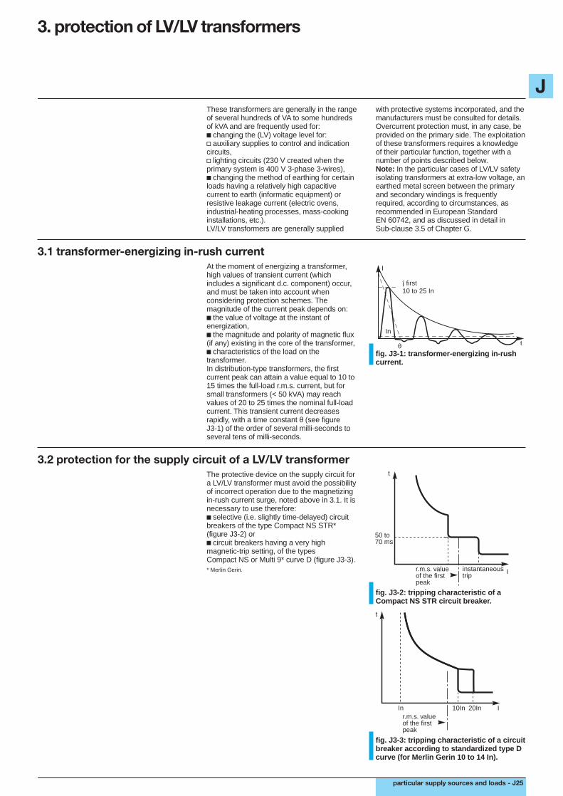
3.1 transformer-energizing in-rush currentAt the moment of energizing a transformer,high values of transient current (whichincludes a significant d.c. component) occur,and must be taken into account whenconsidering protection schemes. Themagnitude of the current peak depends on:c the value of voltage at the instant ofenergization,c the magnitude and polarity of magnetic flux(if any) existing in the core of the transformer,c characteristics of the load on thetransformer.In distribution-type transformers, the firstcurrent peak can attain a value equal to 10 to15 times the full-load r.m.s. current, but forsmall transformers (< 50 kVA) may reachvalues of 20 to 25 times the nominal full-loadcurrent. This transient current decreasesrapidly, with a time constant θ (see figureJ3-1) of the order of several milli-seconds toseveral tens of milli-seconds.
Î first10 to 25 In
In
θ
I
t
fig. J3-1: transformer-energizing in-rushcurrent.
3.2 protection for the supply circuit of a LV/LV transformerThe protective device on the supply circuit fora LV/LV transformer must avoid the possibilityof incorrect operation due to the magnetizingin-rush current surge, noted above in 3.1. It isnecessary to use therefore:c selective (i.e. slightly time-delayed) circuitbreakers of the type Compact NS STR*(figure J3-2) orc circuit breakers having a very highmagnetic-trip setting, of the typesCompact NS or Multi 9* curve D (figure J3-3).* Merlin Gerin.
t
50 to70 ms
Iinstantaneoustrip
r.m.s. valueof the firstpeak
fig. J3-2: tripping characteristic of aCompact NS STR circuit breaker.
Inr.m.s. valueof the firstpeak
t
I10In 20In
fig. J3-3: tripping characteristic of a circuitbreaker according to standardized type Dcurve (for Merlin Gerin 10 to 14 In).

J
J26 - particular supply sources and loads
3. protection of LV/LV transformers (continued)
3.2 protection for the supply circuit of a LV/LV transformer (continued)
Example (figure J3-4)A 400 V 3-phase circuit is supplying a125 kVA 400/230 V transformer (In = 180 A)for which the first in-rush current peak canreach 17 In, i.e. 17 x 180 A = 3,067 A.A Compact NS250 circuit breaker with Irsetting of 200 A would therefore be a suitableprotective device.
A particular case: overload protectioninstalled at the secondary side of thetransformerAn advantage of overload protection locatedon the secondary side, is that the short-circuitprotection on the primary side can be set at ahigh value, or alternatively a circuit breakertype MA* may be used. The primary-sideshort-circuit protection setting must, however,be sufficiently sensitive to ensure itsoperation in the event of a short-circuitoccurring on the secondary side of thetransformer (upstream of secondaryprotective devices).* Motor-control circuit breaker, the short-circuit protectiverelay of which is immune to high transient-current peaks, asshown in figure J5-3.
400/230 V125 kVA
3 x 70 mm2
NS250Ntripping unitSTR22SE (Ir = 200)
fig. J3-4: example.
Note: The primary protection is sometimesprovided by fuses, type a M. This practicehas two disadvantages:c the fuses must be largely oversized (atleast 4 times the nominal full-load ratedcurrent of the transformer);c in order to provide isolating facilities on theprimary side, either a load-break switch or acontactor must be associated with the fuses.
3.3 typical electrical characteristics of LV/LV 50 Hz transformers3-phasekVA rating 5 6.3 8 10 12.5 16 20 25 31.5 40 50 63 80 100 125 160 200 250 315 400 500 630 800no-load losses (W) 100 110 130 150 160 170 270 310 350 350 410 460 520 570 680 680 790 950 1160 1240 1485 1855 2160full-load losses (W) 250 320 390 500 600 840 800 1180 1240 1530 1650 2150 2540 3700 3700 5900 5900 6500 7400 9300 9400 11400 11400s.c. voltage (%) 4.5 4.5 4.5 5.5 5.5 5.5 5.5 5.5 5 5 4.5 5 5 5.5 4.5 5.5 5 5 4.5 6 6 5.5 5.51-phasekVA rating 8 10 12.5 16 20 25 31.5 40 50 63 80 100 125 160no-load losses (W) 105 115 120 140 150 175 200 215 265 305 450 450 525 635full-load losses (W) 400 530 635 730 865 1065 1200 1400 1900 2000 2450 3950 3950 4335s.c. voltage (%) 5 5 5 4.5 4.5 4 4 5 5 4.5 5.5 5 5
table J3-5: typical electrical characteristics of LV/LV 50 Hz transformers.
3.4 protection of transformers with characteristics as tabled in J3-5 above, usingMerlin Gerin circuit breakers
3-phase transformers (400 V primary) circuit breakersP (kVA) In (A) Usc % type trip-unit current
rating (A)/type no.5 7 4.5 C60 / NC100 D or K 2010 14 5.5 C60 / NC100 D or K 3216 23 5.5 C60 / NC100 D or K 6320 28 5.5 C60 / NC100 D or K 6325 35 5.5 NC100 D 8031.5 44 5 NC100 D 8040 56 5 NC100 D 8050 70 4.5 NC100 D 10063 89 5 NS100H/L MA100
NS160H/L STR22SE80 113 5 NS160H/L STR22SE100 141 5.5 NS250N/H/L STR22SE125 176 4.5 NS250N/H/L STR22SE
NS400N/H/L STR23SE160 225 5.5 NS250N/H/L STR22SE
NS400N/H/L STR23SE250 352 5 C801N/H/L STR35SE315 444 4.5 C801N/H/L STR35SE400 563 6 C801N/H/L STR35SE500 704 6 C801NH/L STR35SE
C1001N/H/L STR35SE630 887 5.5 C1001N/H/L STR35SE
C1251N/H STR35SE
table J3-6: protection of 3-phase LV/LV transformers with 400 V primary windings.

J
particular supply sources and loads - J27
3-phase transformers (230 V primary) circuit breakersP (kVA) In (A) Usc % type trip-unit current
rating (A)/type no.5 12 4.5 C60 / NC100 D or K 4010 24 5.5 C60 / NC100 D or K 6316 39 5.5 NC100 D 8020 49 5.5 NC100 D 10025 61 5.5 NS100H/L STR22SE31.5 77 5 NS100H/L STR22SE40 97 5 NS100H/L STR22SE50 122 4.5 NS100H/L STR22SE63 153 5 NS250N/H/L STR22SE
NS400N/H/L STR23SE80 195 5 NS250N/H/L STR22SE
NS400N/H/L STR23SE100 244 5.5 NS630N/H/L STR23SE125 305 4.5 C801N/H/L STR35SE160 390 5.5 C801N/H/L STR35SE250 609 5 C801N/H/L STR35SE
C1001N/H/L STR35SE315 767 4.5 C1001N/H/L STR35SE
C1251N/H STR35SE400 974 6 C1251N/H STR35SE
table J3-7: protection of 3-phase LV/LV transformers with 230 V primary windings.
table J3-8: protection of 1-phase LV/LV transformers with 400 V primary windings.
1-phase transformers (400 V primary) circuit breakersP (kVA) In (A) Usc % type trip-unit current
rating (A)/type no.0.1 0.24 13 C60 D or K 10.16 0.39 10.5 C60 D or K 10.25 0.61 9.5 C60 D or K 10.4 0.98 7.5 C60 D or K 20.63 1.54 7 C60 D or K 31 2.44 5.2 C60 D or K 61.6 3.9 4 C60 / NC100 D or K 102 4.88 2.9 C60 / NC100 D or K 102.5 6.1 3 C60 / NC100 D or K 164 9.8 2.1 C60 / NC100 D or K 205 12.2 1.9 C60 / NC100 D or K 326.3 15.4 1.6 C60 / NC100 D or K 408 19.5 5 C60 / NC100 D or K 5010 24 5 C60 / NC100 D or K 6312.5 30 5 C60 / NC100 D or K 6316 39 4.5 NC100 D 8020 49 4.5 NC100 D 10025 61 4.5 NS160H/L STR22SE31.5 77 4 NS160H/L STR22SE40 98 4 NS160H/L STR22SE50 122 4 NS160H/L STR22SE63 154 5 NS250N/H/L STR22SE
NS400N/H/L STR23SE80 195 4.5 NS250N/H/L STR22SE
NS400 STR23SE100 244 5.5 NS630 STR23SE125 305 5 C801N/H/L STR35SE160 390 5 C801N/H/L STR35SE

J
J28 - particular supply sources and loads
1-phase transformers (230 V primary) circuit breakersP (kVA) In (A) Usc % type trip-unit current
rating (A)/type no.0.1 0.4 13 C60 D or K 10.16 0.7 10.5 C60 D or K 20.25 1.1 9.5 C60 D or K 30.4 1.7 7.5 C60 D or K 40.63 2.7 7 C60 D or K 61 4.2 5.2 C60 / NC100 D or K 101.6 6.8 4 C60 / NC100 D or K 162 8.4 2.9 C60 / NC100 D or K 162.5 10.5 3 C60 / NC100 D or K 204 16.9 2.1 C60 / NC100 D or K 405 21.1 1.9 C60 / NC100 D or K 506.3 27 1.6 C60 / NC100 D or K 638 34 5 NC100 D 8010 42 5 NC100 D 10012.5 53 5 NC100 D 10016 68 4.5 NS160H/L STR22SE20 84 4.5 NS160H/L STR22SE25 105 4.5 NS250N/H/L STR22SE
NS250N/H/L STR22SE31.5 133 4 NS250N/H/L STR22SE40 169 4 NS250N/H/L STR22SE
NS400N/H/L STR23SE50 211 5 NS250N/H/L STR22SE
NS400N/H/L STR23SE63 266 5 NS630N/H/L STR23SE80 338 4.5 C801N/H/L STR35SE100 422 5.5 C801N/H/L STR35SE125 528 5 C801N/H/L STR35SE160 675 5 C801N/H/L STR35SE
C1001N/H/L STR35SE
3. protection of LV/LV transformers (continued)
3.4 protection of transformers with characteristics as tabled in J3-5 above, usingMerlin Gerin circuit breakers (continued)
table J3-9: protection of 1-phase LV/LV transformers with 230 V primary windings.

J
particular supply sources and loads - J29
4. lighting circuits
the presence of adequate lightingcontributes to the satety of persons.
The planning and realization of a lightinginstallation requires a sound understanding ofthe materials installed, together withfamiliarity with the rules for safety against firehazards in establishments receiving thepublic.
In fact, the provision of adequate illuminationin the event of fire or other catastrophiccircumstances is of great importance inreducing the likelihood of panic, and inpermitting the necessary safety manœuvresto be carried out.
definitionsNormal lighting refers to the installationdesigned for everyday use.Emergency lighting must ensure easyevacuation of persons from the premisesconcerned, in the event that the normallighting system fails. Furthermore, emergencylighting must be adequate to allow anyparticular safety manœuvres provided in thepremises to be carried out.
Standby lighting is intended to substitutenormal lighting, where the latter fails. Standbylighting permits everyday activities tocontinue more or less normally, depending onthe original design specification, and on theextent of the normal lighting failure. Failure ofthe standby lighting system mustautomatically switch on the emergencylighting system.
emergency lighting is intendedto facilitate the evacuation of personsin case of fire or other panic-causingsituations, when normal lightingsystems may have failed.
4.1 service continuity
continuity of normal lighting servicemust be sufficient, independent ofother supplementary systems.
normal lightingRegulations governing the minimumrequirements for ERP (EstablishmentsReceiving the Public) in most Europeancountries, are as follows:c installations which illuminate areasaccessible to the public must be controlledand protected independently frominstallations providing illumination to otherareas;c loss of supply on a final lighting circuit (i.e.fuse blown or CB tripped) must not result intotal loss of illumination in an area which iscapable of accommodating more than50 persons;c protection by RCDs (residual currentdifferential devices) must be divided amongstseveral devices (i.e. more than one devicemust be used).
emergency lightingThese schemes include illuminatedemergency exit signs and directionindications, as well as general lighting.c emergency exit indicationsIn areas accommodating more than50 persons, luminous directional indicationsto the nearest emergency exits must beprovided;c general emergency lightingGeneral lighting is obligatory when an areacan accommodate 100 persons or more(50 persons or more in areas below groundlevel).A fault on a lighting distribution circuit mustnot affect any other circuit:v the discrimination of overcurrent-protectionrelays and of RCDs must be absolute, so thatonly the faulty circuit will be cut off,v the installation must be an IT scheme, ormust be entirely class II, i.e. doubly-insulated.
Sub-clause 4.7 describes different kinds ofsuitable power supplies.
in emergency lighting circuits,absolute discrimination betweenprotective devices on the differentcircuits must be provided.

J
J30 - particular supply sources and loads
4. lighting circuits (continued)
4.2 lamps and accessories (luminaires)fluorescent tubesFor normal operation a fluorescent tuberequires a ballast and a starter (device forinitiating the luminous discharge).c the ballast is an iron-cored inductor,permanently connected in series with thetube; its function is threefold, viz:v to limit the preheating current during the(brief) starting period,v to provide a pulse of high voltage at the endof the starting period to strike the initial arc,v to stabilize the current through the luminouscolumn (hence the term “ballast”).
The presence of the ballast means that thepower-factor (cos ø) of the circuit is low (ofthe order 0.6) with the correspondingconsumption of reactive energy, which isgenerally metered. For this reason eachfluorescent lamp is normally provided with itsown power-factor-correction capacitor.
c the starter is a switch, which, by breakingthe (electrode-preheating) current passingthrough the ballast, causes a high-voltagetransient pulse to appear across the tube.This causes an arc (in the form of a gaseousdischarge) to be established through thetube. The discharge is then self-sustaining atnormal voltage.The ballast, capacitor and the tube, engenderdisturbances during the periods of starting,steady operation and extinction. Thesedisturbances are analysed in table J4-1below.
switching-on disturbancesc high current peak to chargecapacitor; order of magnitude 10 Infor 1 sec.A number of lamps on one circuitcan result in peaks of 300-400 A for0.5 ms.This can cause a CB to trip, or thewelding of contacts in a contactor. Inpractice, limit each circuit to 8 tubesper contactor;c moderate overload at thebeginning of steady operatingcondition (1.1-1.5 In for 1 sec)according to type of starter.
c no high current peak as notedabove;c same order of moderate overloadat beginning of steady operatingcondition as for the single tubenoted above.This arrangement is recommendedfor difficult cases.
c can generate a current peak atstart;c can cause leakage to earth of HFcurrent (at 30 kHz) via the phaseconductor capacitances to earth.
single-phase fluorescentlamp with its individualp.f. correction capacitor
single-phase twin-tubefluorescent lamp witheach tube having itsown starter and seriesballast. One of the tubeshas a capacitorconnected in series withits ballast. The two setsof equipment areconnected in parallel.The arrangement isknown internationally asa “duo”-circuit luminaire.The capacitor displacesthe phase of the currentthrough its tube, tonullify the flicker effect,as well as correcting theoverall p.f.
fluorescent lamp withHF ballast
Advantages:Energy savings of theorder of 25%.Rapid one-shot start.No flicker orstroboscopic effects.
123
A
B
ballaststarter
starter
table J4-1: analysis of disturbances in fluorescent-lighting circuits.
switching-off disturbancesno particular problems
no particular problems
no particular problems
steady-operating disturbancescirculation of harmonic currents(sinusoidal currents at frequencies equalto whole-number multiples of 50(or 60) Hz:c delta-connected lamps (seeAppendix J2) (3-ph 3-wire 230 V system)
presence of 5th and 7th harmonics at verylow level
c star-connected lamps (3-ph 4-wire400/230 V system)
presence of 3 rd harmonic currents in theneutral, which can reach 70 to 80% of thenominal phase current.In this case, therefore, the c.s.a. of theneutral conductor must equal that of thephase conductors.
123
1
3N
2

J
particular supply sources and loads - J31
4.3 the circuit and its protectiondimensions and protection of theconductorsThe maximum currents in the circuits can beestimated using the methods discussed inChapter B.Accordingly, account must be taken of:c the nominal power rating of the lamp andthe ballast;c the power factor.The temperature within the distribution panelalso influences the choice of the protectivedevice (see Chapter H2 Sub-clause 4.4).In general tables are available frommanufacturers to assist in making a choice.
Note: for circuits in which large peak currentsoccur (at times of switching on) and theirmagnitude is such that CB tripping is apossibility, the cable size is chosen after theprotective CB (with an instantaneous tripsetting sufficient to remain closed during thecurrent peaks) has been selected. See theNote following table J4-2.
factor of simultaneity ks(diversity)A particular feature of large (e.g. factory)lighting circuits is that the whole load is “on”or “off”, i.e. there is no diversity. Furthermore,even among a number of lighting circuits froma given distribution panel, the factor ks isgenerally near unity.
Consequently, the interior of distributionpanels supplying lighting schemes arefrequently at an elevated temperature, animportant consideration to be taken intoaccount when selecting protective devices.
4.4 determination of the rated current of the circuit breakerThe rated current of a circuit breaker isgenerally chosen according to the rating ofthe circuit conductors it is protecting (in theparticular circumstances in the Note of 4.3above, however, the reverse procedure wasfound to be necessary). The circuit conductorratings are defined by the maximum steadyload current of the circuit.
The following tables allow direct selection ofcircuit breaker ratings for certain particularcases.
power 230 V 1-phase 230 V 3-phase 400 V 3-phase(kW) current rating In (A) current rating In (A) current rating In (A)1 6 3 21.5 10 4 32 10 6 42.5 16 10 43 16 10 63.5 20 10 104 20 16 104.5 25 16 105 25 16 106 32 20 107 32 20 168 40 25 169 50 25 1610 50 32 20
table J4-2: protective circuit breaker ratings for incandescent lamps and resistive-typeheating circuits (see Note below).
Note: at room temperature the filament resistance of a 100 W 230 V incandescent lamp isapproximately 34 ohms. Some milli-seconds after switching on, the filament resistance rises to2302/100 = 529 ohms.The initial current peak at the instant of switch closure is therefore practically 15 times its normaloperating current.A similar (but generally less severe) transient current peak occurs when energizing any resistive-type heating appliance.

J
J32 - particular supply sources and loads
single-phase distribution 230 Vthree-phase distribution + N : 400 V phase/phasetypes de tube number of luminaires per phaseluminaires rating
(W)single-phase 18 7 14 21 42 70 112 140 175 225 281 351 443 562 703with capacitor 36 3 7 10 21 35 56 70 87 112 140 175 221 281 351
58 2 4 6 13 21 34 43 54 69 87 109 137 174 218duo circuit 2x18= 36 3 7 10 21 35 56 70 87 112 140 175 221 281 351with 2x36= 72 1 3 5 10 17 28 35 43 56 70 87 110 140 175capacitor 2x58= 116 1 2 3 6 10 17 21 27 34 43 54 68 87 109current rating of1-,2-,3 -or 4- pole CBs 1 2 3 6 10 16 20 25 32 40 50 63 80 100
4. lighting circuits (continued)
4.4 determination of the rated current of the circuit breaker (continued)
The following table (J4-3) is valid for 230 V and 400 V installations, with or without individualpower-factor correcting capacitors.mercury vapour fluorescent lampsP i 700 W 6 AP i 1000 W 10 AP i 2000 W 16 Ametal-halogen mercury-vapour lampsP 275 W 6 AP 1000 W 10 AP 2000 W 16 Ahigh-pressure sodium discharge lampsP 400 W 6 AP 1000 W 10 A
table J4-3: maximum limit of rated current per outgoing lighting circuit, for high-pressuredischarge lamps.
Calculation for tubes with p.f. capacitor; connected in star
number of tubes per phase = 0.8 C x 0.86 V Pu x 1.25
where: C = current rating of C B, V = phase/neutral voltage, 0.86 = cos ø of circuit, 0.8 = deratingfactor for high temperature in CB housing, 1.25 = factor for watts consumed by ballast,Pu = nominal power rating of tube (W).
three-phase 3 wire system(230 V) phase/phasetypes de tube number of luminaires per phaseluminaires rating
(W)single-phase 18 4 8 12 24 40 64 81 101 127 162 203 255 324 406with capacitor 36 2 4 6 12 20 32 40 50 64 81 101 127 162 203
58 1 2 3 7 12 20 25 31 40 50 63 79 100 126duo circuit 2x18= 36 2 4 6 12 20 32 40 50 64 81 101 127 162 203with 2x36= 72 1 2 3 6 10 16 20 25 32 40 50 63 81 101capacitor 2x58= 116 0 1 1 3 6 10 12 15 20 25 31 39 50 63current rating of2- or 3- pole CBs 1 2 3 6 10 16 20 25 32 40 50 63 80 100
Calculation for tubes with p.f. capacitor; connected in delta
number of tubes per phase = 0.8 C x 0.86 U Pu x 1.25 x e
where: U = phase/phase voltage
tables J4-4: current ratings of circuit breakers related to the number of fluorescentluminaires to be protected.
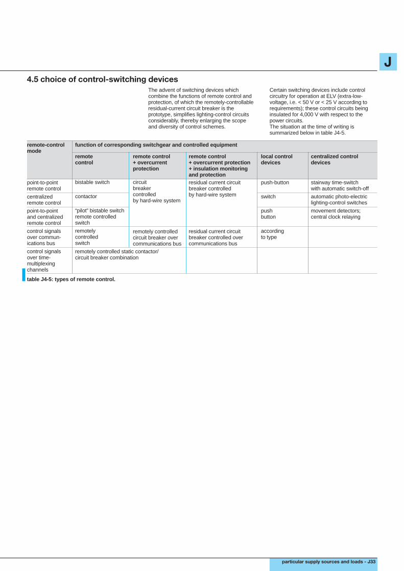
J
particular supply sources and loads - J33
4.5 choice of control-switching devicesThe advent of switching devices whichcombine the functions of remote control andprotection, of which the remotely-controllableresidual-current circuit breaker is theprototype, simplifies lighting-control circuitsconsiderably, thereby enlarging the scopeand diversity of control schemes.
Certain switching devices include controlcircuitry for operation at ELV (extra-low-voltage, i.e. < 50 V or < 25 V according torequirements); these control circuits beinginsulated for 4,000 V with respect to thepower circuits.The situation at the time of writing issummarized below in table J4-5.
remote-controlmode
point-to-pointremote control
centralizedremote control
point-to-pointand centralizedremote control
control signalsover commun-ications bus
control signalsover time-multiplexingchannels
remotecontrol
bistable switch
contactor
“pilot” bistable switchremote controlledswitch
remotelycontrolledswitch
remote control+ overcurrentprotection
circuitbreakercontrolledby hard-wire system
remotely controlledcircuit breaker overcommunications bus
remote control+ overcurrent protection+ insulation monitoringand protectionresidual current circuitbreaker controlledby hard-wire system
residual current circuitbreaker controlled overcommunications bus
local controldevices
push-button
switch
pushbutton
accordingto type
centralized controldevices
stairway time-switchwith automatic switch-off
automatic photo-electriclighting-control switches
movement detectors;central clock relaying
function of corresponding switchgear and controlled equipment
remotely controlled static contactor/circuit breaker combination
table J4-5: types of remote control.

J
J34 - particular supply sources and loads
4. lighting circuits (continued)
4.6 protection of ELV lighting circuitsA LV/ELV transformer is often located in aninaccessible position, so that protectioninstalled on the secondary side would beequally difficult to reach.For this reason the protection is commonlyprovided on the primary circuit.The protective device is therefore chosen:c to provide switching control (Multi 9type C CB, or type aM fuses);c to ensure protection against short-circuits.It must therefore be verified that:v in the case of a CB, the minimum value ofshort-circuit current exceeds by a suitablemargin the short-circuit magnetic relay settingIm of the CB concerned,v in the case of fuses it is also necessary toensure that the I2t energy let-through of thefuse(s) at minimum short-circuit current iswell below the level of the thermal withstandcapacity of the circuit conductors,c if necessary, overload protection must beprovided. If the number of lamps on the circuithas been correctly chosen, however,overload protection is not necessary.
Example:The s.c. current Isc2 at the secondaryterminals of a single-phase LV/ELVtransformer is equal toUs where Zs = Us2 x Usc %Zs Pn 100
so that Isc2 = Pn x 100 = 400 x 100 Us x Usc% 12 x 6= 555 A which gives Isc1 = 29 A in theprimary circuit.
Circuit breaker type C trips if the primarycurrent u Im1 = 10 In = 20 A, whichcorresponds to a secondary current of
20 x 230 = 383 A 12The maximum resistance of the ELV (i.e.secondary) circuit* may be deduced fromthese two secondary s.c. currents, viz: 555 Aand 383 A as follows:
Rc = U2 - V2 = 12 - 12 = 0.0313 - 0.0216
Im2 Isc2 383 555= 9.7 mΩ* from the transformer terminals to the ELV distributionboard.
Note: The true value of Rc permitted is,in principle, greater than 9.7 milli-ohms,because the source impedance (i.e. U2/555,will be mainly reactive, not resistive, as(implied) in the example. However,for simplicity, and to automatically providea safety margin under all circumstances,an arithmetic subtraction, as shown,is recommended.
The maximum length of the 12 V circuitbased on 9.7 mΩ will therefore be:Rc (mΩ) x S (mm2) in metres = 9.7 x 6 2 x 22.5 (µΩ.mm) 2 x 22.5for a 6 mm2 copper cable = 1.3 mIt is then necessary to check that this lengthis sufficient to reach the 12 V distributionboard, where the outgoing ways areprotected with other devices. If the length isinsufficient, then an increase in the c.s.a. ofthe conductors, proportional to the increasedlength required, will satisfy the constraint formaximum Rc; for example, a conductor of10 mm2 would allow 1.3 x 10/6 = 2.2 m ofcircuit length in the above case.
230/12 V400 VAUsc = 6%
LV
2 A
ELV
secondarycircuit
fig. J4-6: example.

J
particular supply sources and loads - J35
4.7 supply sources for emergency lightingSupply sources for emergency-lightingsystems must be capable of maintaining thesupply to all lamps in the most unfavourablecircumstances likely to occur, and for a periodjudged necessary to ensure the totalevacuation of the premises concerned,with (in any case) a minimum of one hour.
compatibility betweenemergency lighting sources andother parts of the installationEmergency-lighting sources must supplyexclusively the circuits installed only foroperation in emergency situations.Standby lighting systems operate to maintainillumination, on failure of normal lightingcircuits (generally in non-emergencycircumstances). However, failure of standbylighting must automatically bring theemergency lighting system into operation.
Central sources for emergency supplies mayalso be used to provide standby supplies,provided that the following conditions aresimultaneously fulfilled:c where there are several sources, the failureof one source must leave sufficient capacityin service to maintain supply to all safetysystems, with automatic load shedding ofnon-essential loads (if necessary);c the failure of one source, or one equipmentconcerned with safety, must leave all othersources and safety equipments unaffected;c any safety equipment must be arranged toreceive supply from any source.
classification of emergency-lighting schemesMany countries have statutory regulationsconcerning safety in buildings and areasintended for public gatherings.Classification of such locations leads to thedetermination of suitable types of solutions,authorized for use in emergency-lightingschemes in the different areas.The following four classifications are typical.
Type AThe lamps are supplied permanently andtotally during the presence of the public by asingle central source (battery of storage cells,or a heat-engine-driven generator). Thesecircuits must be independent of any othercircuits (1).
Type BThe lamps are permanently supplied duringthe presence of the public, either:c by a battery to which the lamps arepermanently connected, and which is onpermanent trickle charge from a normallighting source, or,c by a heat-engine-driven generator, thecharacteristics of which also assure suppliesto essential loads within one second (sincethe set is already running and supplying theemergency lighting) in the event of failure ofthe normal power supply, or,c by autonomous units which are normallysupplied and permanently alight from thenormal lighting supply, and which remainalight (for at least one hour), on the loss ofnormal supply, by virtue of a self-containedbattery. The battery is trickle-charged innormal circumstances.These units have fluorescent lamps forgeneral emergency lighting, and fluorescentor incandescent lamps for exit and direction-indicating signs.The circuits for all emergency lamps must beindependent of any other circuits (1).
Type CThe lamps may, or may not, be supplied innormal conditions and, if supplied, may befed from the normal lighting system, or fromthe emergency-lighting supply.c the emergency-lighting batteries must bemaintained on charge from the normal sourceby automatically regulated systems, thatensure a minimum of capacity equal to thefull emergency-lighting load for one hour;c the heat-engine-driven generator sets mustbe capable of automatically picking-up the fullemergency lighting load from a standby(stationary) condition, in less than15 seconds, following the failure of normalsupply.The engine start-up power is provided by abattery which is capable of six startingattempts, or by a system of compressed air.Minimum reserves of energy in the twosystems of start-up must be maintainedautomatically.c failures in the central emergency supplysource must be detected at a sufficientnumber of points and adequately signalled tosupervisory/maintenance personnel;c autonomous units may be of thepermanently-lit type or non-permanently-littype.The circuits for all emergency lamps must beindependent of any other circuits (2).
Type DThis type of emergency lighting compriseshand-carried battery-powered (primary orsecondary cells) at the disposal of servicepersonnel or the public.(1) Circuits for types A and B, in the case of a centralemergency power source, must also be fire-resistant.Conduit boxes, junction sleeves and so on must satisfynational standard heat tests, or the circuits must be installedin protective cable chases, trunking, etc. capable of assuringsatisfactory performance for at least one hour in the event offire.(2) Cable circuits of type C are not required to comply withthe conditions of (1).

J
J36 - particular supply sources and loads
5. asynchronous motors
the asynchronous (i.e. induction)motor is robust and reliable,and very widely used. 95%of motors installed around the worldare asynchronous. The protectionof these motors is consequentlya matter of great importancein numerous applications.
The consequences of an incorrectly protectedmotor can include the following:c for persons:v asphyxiation due to the blockage of motorventilation,v electrocution due to insulation failure in themotor,v accident due to sticking (contact welding) ofthe controlling contactor;c for the driven machine and the process:v shaft couplings and axles, etc. damageddue to a stalled rotor,v loss of production,v manufacturing time delayed;c for the motor:v motor windings burnt out due to stalledrotor,v cost of dismantling and reinstating orreplacement of motor,v cost of repairs to the motor.
It is, therefore, the safety of persons andgoods, and reliability and availability levelswhich must influence the choice of protectiveequipment.In economic terms, it is the overall cost offailure which must be considered; a penaltywhich is increasingly severe as the size of themotor, and difficulties of access to it increase.Loss of production is a further, and evidentlyimportant factor.
A motor power-supply circuit presents certainconstraints not normally encountered in other(common) distribution circuits, owing to theparticular characteristics, specific to motors,such as:c heavy start-up current (see figure J5-1)which is highly reactive, and can therefore bethe cause of an important voltage drop;c number and frequency of start-upoperations are generally high;c the heavy start-up current means thatmotor overload protective devices must haveoperating characteristics which avoid trippingduring the starting period.
I"IdIn
= 8 to 12 In= 5 to 8 In= nominal motor current
In Id I" I
20 to30 ms
t d1 to 10s
t
fig. J5-1: direct-on-line starting-currentcharacteristics of an induction motor.
specific features of motorperformance influence the power-supply circuits required forsatisfactory operation.
5.1 protective and control functions required
functions to be provided generallyinclude:c basic protective devices,c electronic control equipment,c preventive or limitative protectionequipment.
Functions generally provided are:c basic protection, including:v isolating facility,v manual local and/or remote control,v protection against short-circuits,v protection against overload;c electronic controls consisting of:v progressive “soft-start” motor starter, or,v speed controller;c preventive or limitative protection by meansof:v temperature sensors,v multi-function relays,v permanent insulation-resistance monitor orRCD (residual-current differential device).
Table J5-2 below, shows diverse motor-circuitconfigurations commonly used in LVdistribution boards.

J
particular supply sources and loads - J37
basic protection fuse-disconnector circuit breaker* motor circuit contactor circuit+ discontactor + discontactor breaker* + contactor breaker* ACPA(using thermal relay) (using thermal relay)
standards
disconnection(or isolation)
manual remotecontrol control
short-circuitprotection
* circuit breaker includes disconnector capability
overload c large power range c large power range c method is simple c low installation costsprotection c allow all types c avoids need to stock and compact for c no maintenance
of starting schemes fuse cartridges low-power motors c high degree of safetyc a well-proven method c disconnection is and reliabilityc suitable for systems visible in certain cases c suitable for systemshaving high fault c identification of having high fault levelslevels the reason for tripping c long electrical life
refer also to Chapter H2, Sub-clause 2-2 i.e. short circuitor overload
electronic controls
preventive or limitativeprotection devices
progressive “soft-start”starter devicec limitationv current peaks Iv voltage drops Uv mechanical constraintsduring start-up periodc thermal protection isincorporated
speedcontrollerc from 2 to 130 % ofnominal speedc thermal protection isincorporatedc possibility ofcommunication facilities
thermal sensorsProtection against abnormalheating of the motor bythermistance-type sensors in themotor windings, connected toassociated relays.
multi-function relaysDirect and indirect thermal protection against:c the starting period excessively long, orstalled-rotor conditionc imbalance, absence or inversion of phasevoltagesc earth fault or excessive earth-leakage currentc motor running on no-load; motor blockedduring start-upc pre-alarm overheating indication
permanent insulation-to-earth monitor andRCD (residual-current differential relay)Protection against earth-leakage currentand short-circuits to earth.Signalled indication of need for motormaintenance or replacement.
table J5-2: commonly-used types of LV motor-supply circuits.

J
J38 - particular supply sources and loads
5. asynchronous motors (continued)
5.2 standardsThe international standards coveringmaterials discussed in this Sub-clause are:IEC 947-2, 947-3, 947-4-1, and 947-6-2.These standards are being adopted (oftenwithout any changes) by a number ofcountries, as national standards.
5.3 basic protection schemes: circuit breaker / contactor / thermal relay
functions to be implemented are:c control (start/stop),c isolation (safety duringmaintenance),c protection against short-circuits,c specific protection as noted inSub-clause 5.1Where several different devices areused to provide protection, co-ordination between them isnecessary.
The control and protection of a motor can beprovided by one, two or three devices, whichshare the required functions of:c control (start/stop);c disconnection (isolation) for safety ofpersonnel during maintenance work;c short-circuit protection;c protection specific to the particular motor(but at least thermal relay overcurrentprotection).When these functions are performed byseveral devices, co-ordination between themis essential. In the case of an electrical faultof any kind, none of the devices involvedmust be damaged, except items for whichminor damage is normal in the particularcircumstances, e.g. replaceable arcingcontacts in certain contactors, after a givennumber of service operations, and so on...The kind of co-ordination required dependson the necessary degree of service continuityand on safety levels, etc.
t
In Is
limit of thermal-relay constraint
short-circuit trippingcharacteristicof the circuit breaker(type MA)
l
circuitbreaker
contactor
thermalrelay
câble
motor(nominal current In)
end ofstart-upperiod
ts1 to10 s
20 to30 ms
I" Imagn.
cable thermal-withstandlimit
characteristicsof thermal relay
range 1.05 - 1.20 In
short-circuit-currentbreaking capacities
magneticrelay
circuit breaker only
CB plus contactor (see Note)
among the many possible methodsof protecting a motor, the associationof a circuit breaker incorporating aninstantaneous magnetic trip for short-circuit protection and a contactor witha thermal overload relay* providesmany advantages.
fig. J5-3: tripping characteristics of a circuit breaker (type MA)** andthermal-relay / contactor (1) combination.AdvantagesThis combination of devices facilitatesinstallation work, as well as operation andmaintenance, by:c the reduction of the maintenance work load:the CB avoids the need to replace blownfuses and the necessity of maintaining astock (of different sizes);c better continuity performance: a motorcircuit can be re-energized immediatelyfollowing the elimination of a fault;c additional complementary devicessometimes required on a motor circuit areeasily accommodated;c tripping of all three phases is assured(thereby avoiding the possibility of “single-phasing”);c full-load current switching possibility (byCB) in the event of contactor failure, e.g.contact welding;
c interlocking;c diverse remote indications;c better protection for the starter for short-circuit currents up to about 30 In (seefigure J5-3).In the majority of cases short-circuit faultsoccur at the motor, so that the current islimited by the cable and the wiring of thestarter (e.g. the direct-acting trip coil of theCB).c possibility of adding RCD:v an RCD of 500 mA sensitivity practicallyeliminates fire risk due to leakage current,v protection against destruction of the motor(short-circuiting of laminations) by the earlydetection of earth-fault currents (300 mA to30 A);c etc.
* The association of an overload relay and a contactor is referred to as a “discontactor” in some countries.** Merlin Gerin.

J
particular supply sources and loads - J39
Note: When short-circuit currents are veryhigh, the contacts of some contactors may bemomentarily forced open by electro-magneticrepulsion, so that two sets of contacts (i.e.those of the CB and those of the contactor)are acting in series. The combinationeffectively increases the s.c. current-breakingcapacity above that of the CB alone.
ConclusionThe association circuit breaker / contactor /thermal relay(1) for the control and protectionof motor circuits is eminently appropriatewhere:c the maintenance service for an installationis reduced, which is generally the case intertiary and small-and medium-sizedindustrial enterprises;c the job specification calls forcomplementary functions;c there is an operational requirement for aload-breaking facility in the event of contactwelding of the contactor.(1) a contactor in association with a thermal relay iscommonly referred to as a discontactor.
standardization of theassociation of circuit breakers/discontactorsCategories of contactorThe standard IEC 947-4 gives utilizationcategories which considerably facilitate thechoice of a suitable contactor for a givenservice duty.The utilization categories advise on:c a range of functions for which the contactormay be adapted;c its current breaking and makingcapabilities;c standard test values for expected lifeduration on load, according to its utilization.The following table gives some typicalexamples of the utilization categoriescovered.
utilization application characteristicscategoryAC-1 Non-inductive (or slightly inductive) loads: cos ø u 0.95 (heating, distribution)AC-2 Starting and switching off of slip-ring motorsAC-3 Cage motors: starting, and switching off motors during runningAC-4 Cage motors: starting, plugging, inching
table J5-4: utilization categories for contactors (IEC 947-4).
Types of co-ordinationFor each association of devices, a type of co-ordination is given, according to the state ofthe constituant parts following a circuitbreaker trip out on fault, or the opening of acontactor on overload.IEC 947-4-1 defines two types of co-ordination, type 1 and type 2, which setmaximum allowable limits of deterioration ofswitchgear, which must never present adanger to personnel.c type 1: deterioration of the contactor and/orof its relay is acceptable under 2 conditions:v no risk for the operator,v all elements other than the contactor and itsrelay must remain undamaged;c type 2: burning, and the risk of welding ofthe contacts of the contactor are the onlyrisks allowed.
Which type to choose?The type of co-ordination to adopt dependson the parameters of exploitation, and mustbe chosen to satisfy (optimally) the needs ofthe user and the cost of installation.c type 1:v qualified maintenance service,v volume and cost of switchgear reduced,v continuity of service not demanded, orprovided by replacement of motor-starterdrawer;c type 2:v continuity of service imperative,v no maintenance service,v specifications stipulating this type of co-ordination.

J
J40 - particular supply sources and loads
5. asynchronous motors (continued)
5.3 basic protection schemes: circuit breaker / contactor / thermal relay (continued)
key points in the successfulassociation of a circuit breakerand a discontactor
1 CB magnetic-trip performance curve2 thermal-relay characteristic3 thermal-withstand limit of the thermal relay
Compact NStype MA
Isc ext.
2
13
t
I
fig. J5-5: the thermal-withstand limit of the thermal relay must be to the right of the CBmagnetic-trip characteristic.
Standards define precisely all the elementswhich must be taken into account to realize acorrect co-ordination of type 2:c absolute compatibility between the thermalrelay of the discontactor and the magnetic tripof the circuit breaker. In figure J5-5 thethermal relay is protected if its limit boundaryfor thermal withstand is placed to the right ofthe CB magnetic trip characteristic curve.In the case of a motor-control circuit breakerincorporating both magnetic and thermaldevices, co-ordination is provided in thedesign;
c the short-circuit current breaking rating ofthe contactor must be greater than theregulated threshold of the CB magnetic triprelay, since it (the contactor) must be capableof breaking a current which has a value equalto, or slightly less than, the setting of themagnetic relay (as seen from figure J5-5);c a reliable performance of the contactor andits thermal relay when passing short-circuitcurrent, i.e. no excessive deterioration ofeither device and no welding of contactorcontacts.
short-circuit current-breakingcapacity of a combination circuitbreaker + contactorIn the studies, the s.c. current-breakingcapacity which must be compared to theprospective short-circuit current is:c either, that of the CB + contactorcombination, if these devices are physicallyclose together (e.g. in the same drawer orcompartment of a MCC*). A short-circuitdownstream of the combination will be limitedto some extent by the impedances of thecontactor (see previous Note) and thethermal relay. The combination can thereforebe used on a circuit for which the prospectiveshort-circuit current level exceeds the rateds.c. current-breaking capacity of the circuitbreaker. This feature very often presents asignificant economic advantage;c or, that of the CB only, for the case wherethe contactor is separated from the CB(so that a short-circuit is possible on theintervening circuit). For such a case,IEC 947-4-1 requires the rating of the circuitbreaker to be equal to or greater than theprospective short-circuit current at its point ofinstallation.* Motor Control Centre.
it is not possible to predict the s.c.current-breaking capability of a CB +contactor combination. Laboratorytests and calculations bymanufacturers are necessary todetermine which type of CB toassociate with which contactor, andto establish the s.c. breaking capacityof the combination.Tables are published by Merlin Geringiving this information in their“LV Distribution” catalogue.
M
fig. J5-6: circuit breaker and contactormounted in juxtaposition.
M
fig. J5-7: circuit breaker and contactorseparately mounted, with interveningcircuit conductors.

J
particular supply sources and loads - J41
choice of instantaneousmagnetic-trip relay for the circuitbreakerThe operating threshold must never be lessthan 12 In for this relay, in order to avoidpossible tripping due to the first current peakduring start-up. This current peak can varyfrom 8 In to 11 or 12 In.
5.4 preventive or limitative protection
preventive or limitative protectiondevices detect signs of impendingfailure, so that action can be taken(automatically or by operatorintervention) to avoid or limit theotherwise inevitable consequences.
The main protection devices of this type formotor are:c thermal sensors in the motor (windings,bearings, cooling-air ducts, etc.);c multifunction protections;c insulation-failure detection devices onrunning, or stationary motor.
thermal sensorsThermal sensors are used to detect abnormaltemperature rise in the motor by directmeasurement.The thermal sensors are generally embeddedin the stator windings (for LV motors), thesignal being processed by an associatedcontrol device acting to trip the circuit breaker(figure J5-8).
fig. J5-8: overheating protection bythermal sensors.
multi-function motor-protectionrelayThe multi-function relay, associated with anumber of sensors and indication modules,provides protection for motors, such as:c thermal overload;c rotor stalled, or starting-up period too long;c overheating;c phase current imbalance, loss of onephase, inverse rotation;c earth fault (by RCD);c running on no-load, blocked rotor onstart-up.The advantages of this relay are essentially:c a comprehensive protection, providing areliable, high-performance and permanentmonitoring/control function;c efficient surveillance of all motor-operatingschedules;c alarm and control indications;c possibility of communication viacommunication buses.
fig. J5-9: multi-function protection,typified by the Telemecanique relay, typeLT8 above.
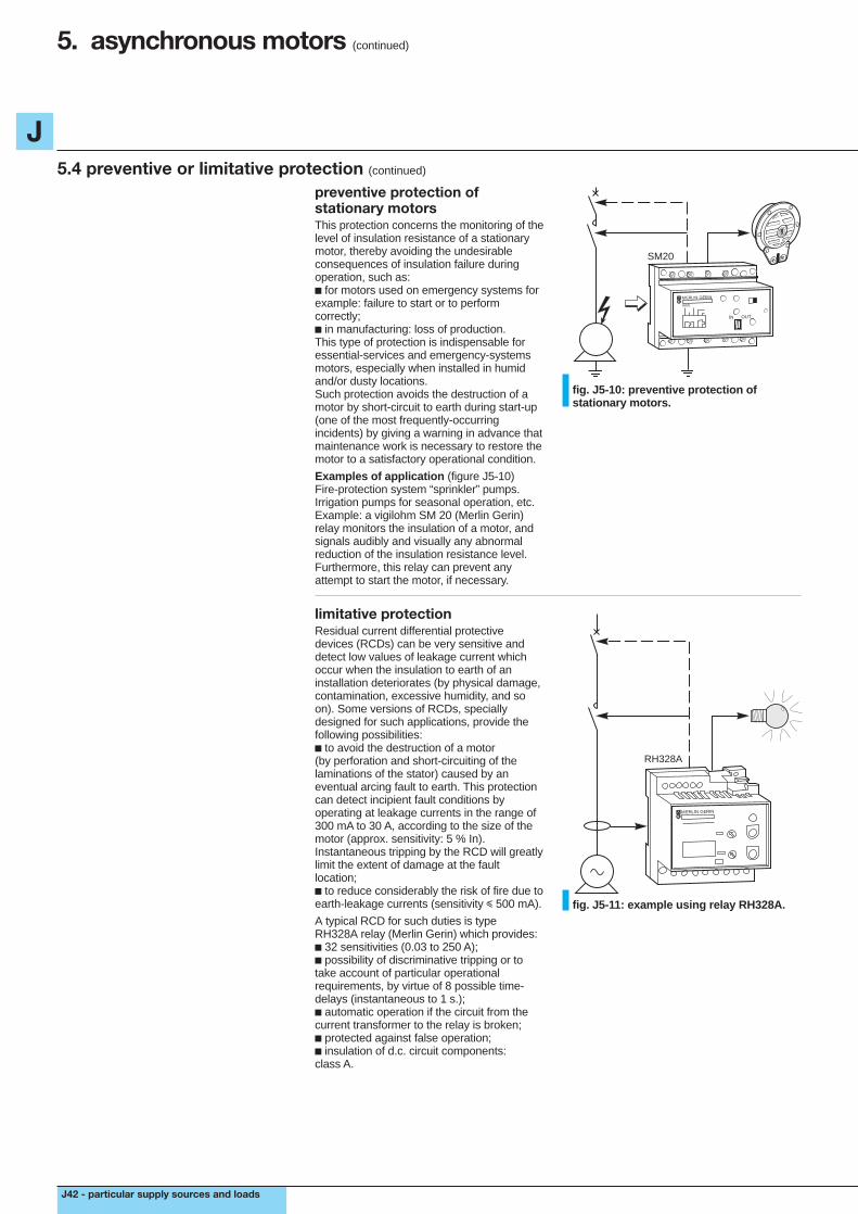
J
J42 - particular supply sources and loads
5. asynchronous motors (continued)
5.4 preventive or limitative protection (continued)
preventive protection ofstationary motorsThis protection concerns the monitoring of thelevel of insulation resistance of a stationarymotor, thereby avoiding the undesirableconsequences of insulation failure duringoperation, such as:c for motors used on emergency systems forexample: failure to start or to performcorrectly;c in manufacturing: loss of production.This type of protection is indispensable foressential-services and emergency-systemsmotors, especially when installed in humidand/or dusty locations.Such protection avoids the destruction of amotor by short-circuit to earth during start-up(one of the most frequently-occurringincidents) by giving a warning in advance thatmaintenance work is necessary to restore themotor to a satisfactory operational condition.
Examples of application (figure J5-10)Fire-protection system “sprinkler” pumps.Irrigation pumps for seasonal operation, etc.Example: a vigilohm SM 20 (Merlin Gerin)relay monitors the insulation of a motor, andsignals audibly and visually any abnormalreduction of the insulation resistance level.Furthermore, this relay can prevent anyattempt to start the motor, if necessary.
SM20
MERLIN GERIN
SM20
IN OUT
fig. J5-10: preventive protection ofstationary motors.
limitative protectionResidual current differential protectivedevices (RCDs) can be very sensitive anddetect low values of leakage current whichoccur when the insulation to earth of aninstallation deteriorates (by physical damage,contamination, excessive humidity, and soon). Some versions of RCDs, speciallydesigned for such applications, provide thefollowing possibilities:c to avoid the destruction of a motor(by perforation and short-circuiting of thelaminations of the stator) caused by aneventual arcing fault to earth. This protectioncan detect incipient fault conditions byoperating at leakage currents in the range of300 mA to 30 A, according to the size of themotor (approx. sensitivity: 5 % In).Instantaneous tripping by the RCD will greatlylimit the extent of damage at the faultlocation;c to reduce considerably the risk of fire due toearth-leakage currents (sensitivity i 500 mA).
A typical RCD for such duties is typeRH328A relay (Merlin Gerin) which provides:c 32 sensitivities (0.03 to 250 A);c possibility of discriminative tripping or totake account of particular operationalrequirements, by virtue of 8 possible time-delays (instantaneous to 1 s.);c automatic operation if the circuit from thecurrent transformer to the relay is broken;c protected against false operation;c insulation of d.c. circuit components:class A.
RH328A
MERLIN GERIN
fig. J5-11: example using relay RH328A.

J
particular supply sources and loads - J43
voltage drop at the terminals of amotor during starting must neverexceed 10% of rated voltage Un.
The importance of limiting voltage dropat the motor during start-upIn order that a motor starts and accelerates toits normal speed in the appropriate time, thetorque of the motor must exceed the loadtorque by at least 70%. However, the startingcurrent is much greater than the full-loadcurrent of the motor; moreover, it is largelyinductive. These two factors are both veryunfavourable to the maintenance of voltageat the motor. Failure to provide sufficientvoltage will reduce the motor torquesignificantly (motor torque is proportional toU2) and will result either in an excessivelylong starting time, or, for extreme cases, infailure to start.
Example:c with 400 V maintained at the terminals of amotor, its torque would be 2.1 times that ofthe load torque;c for a voltage drop of 10% during start-up,the motor torque would be 2.1 x 0.92 = 1.7times the load torque, and the motor wouldaccelerate to its rated speed normally;c for a voltage drop of 15% during start-up,the motor torque would be 2.1 x 0.852 = 1.5times the load torque, so that the motor-starting time would be longer than normal.In general, a maximum allowable voltagedrop of 10% Un is recommended during thestart-up of a motor.
5.5 maximum rating of motors installed for consumers supplied at LVThe disturbances caused on LV distributionnetworks during the start-up of large DOL(direct-on-line) a.c. motors can occasionconsiderable nuisance to neighbouringconsumers, so that most power-supplyauthorities have strict rules intended to limitsuch disturbances to tolerable levels.The amount of disturbance created by agiven motor depends on the “strength” of thenetwork, i.e. on the short-circuit fault level atthe point concerned. The higher the faultlevel, the “stronger” the system and the lowerthe disturbance (principally volt-drop)experienced by neighbouring consumers.For distribution networks in many countries,typical values of maximum allowable starting
currents for DOL motors are shown below intable J5-12.Corresponding maximum power ratings of thesame motors are shown in table J5-13.Since, even in areas supplied by one powerauthority only, “weak” areas of the networkexist as well as “strong” areas, it is alwaysadvisable to secure the agreement of thepower supplier before acquiring the motorsfor a new project.Other (but generally more costly) alternativestarting arrangements exist, which reduce thelarge starting currents of DOL motors toacceptable levels; for example, star-deltastarters, slip-ring motors, “soft start” electronicdevices, etc.
type of motor single- location maximum starting current (A)or three-phase overhead- underground-
line network cable networksingle phase dwellings 45 45
others 100 200three phase dwellings 60 60
others 125 250
table J5-12: maximum permitted values of starting current for direct-on-line LV motors(230/400 V).
type of motor single- single-phase three-phase 400 Vor three-phase 230 Vlocation (kW) direct-on-line other methods
starting at full load of starting(kW) (kW)
dwellings 1.4 5.5 11others overhead line 3 11 22
networkunderground 5.5 22 45cable network
table J5-13: maximum permitted power ratings for LV direct-on-line-starting motors.
5.6 reactive-energy compensation (power-factor correction)The effect of power factor correction on theamount of current supplied to a motor isindicated in table B4 in Chapter BSub-clause 3-1, and the method of correctionin Chapter E Clause 7.

J
J44 - particular supply sources and loads
6. protection of direct-current installations
differences between a.c. and d.c.installationsAlthough the basic design principles in eachcase are similar, there are differences in:c the calculations for short-circuit currents,and;c the choice of protective equipment, sincethe techniques employed for the interruptionof direct current differ in practice from thoseused for alternating current.
6.1 short-circuit currents
in order to calculate the maximumshort-circuit current from a battery ofstorage cells, when the internalresistance of the battery is unknown,the following approximate formulamay be used:Isc = kC where C = the ratedampere-hour capacity of the battery,and k is a coefficent close to 10 (andin any case is less than 20).
battery of storage cells (oraccumulators)For a short-circuit at its output terminals, abattery will pass a current according to Ohm’slaw equal to Isc = Vb/Riwhere: Vb = open circuit voltage of the fully-charged batteryRi = the internal resistance of the battery (thisvalue is normally obtained from themanufacturer of the battery, as a function ofits ampere-hour capacity)When Ri is not known, an approximateformula may be used, namely: Isc = kCwhere C is the ampere-hour rating of thebattery and k is a coefficient close to 10, andin any case is always less than 20.
Example:What is the short-circuit current level at theterminals of a battery with the followingcharacteristics:c 500 Ah capacity;c fully-charged open-circuit voltage 240 V(110 cells at 2.2 V/cell);c discharge rate 300 A;c autonomy 1/2 hour;c internal resistance is 0.5 milli-ohm/cellso that Ri = 110 x 0.5 = 55 mΩ for the battery,
and Isc = 240 x 103 = 4.4 kA 55The short-circuit currents are seen to be(relatively) low.
Isc
fig. J6-1: battery of storage cells.
direct-current generatorIf Vg is the open-circuit voltage of thegenerator and Ri its internal resistance, then:Isc = Vg / Ri.In the absence of precise data, and for a d.c.system of voltage Un, Vg may be taken as1.1 Un.
Example:A d.c. generator rated at 200 kW, 230 V, andhaving an internal resistance of 0.032 ohm,will give a terminal short-circuit current of230 x 1.1 = 7.9 kA 0.032
IccG=
fig. J6-2: direct-current generator.
Isc at any point in an installationIn this case Isc = V Ri + RlWhere Ri is as previously defined,V is either Vb or Vg as previously defined,Rl is the sum of the resistances of the fault-current loop conductors.Where motors are included in the system,they will each (initially) contribute a current ofapproximately 6 In (i.e. six times the nominalfull-load current of the motor) so that:
Isc = V + 6 (In mot) Ri + Rlwhere In mot is the sum of the full-loadcurrents of all running motors at the instant ofshort-circuit.
+
-
fig. J6-3: short-circuit at any point of aninstallation.

J
particular supply sources and loads - J45
6.2 characteristics of faults due to insulation failure, and of protective switchgearDevices for circuit interruption are sensitive tothe level of d.c. voltage at their terminalswhen breaking short-circuit currents.The table below provides the means fordetermining these voltages, which depend onthe source voltage and on the method ofearthing the source.
Note: In the following text the word “pole” hastwo meanings, viz:1. Referring to a d.c. source, for example:the positive pole or the negative pole of abattery or generator.2. Referring to a switch or circuit breaker, forexample:a pole of a circuit breaker makes or breaksthe current in one conductor. A pole of acircuit breaker may be made up of modules,each of which contains a contact. The polemay therefore consist of one module or(particularly in d.c. circuits) several series-connected modules.
Voltage stresses across opening contactsare reduced by the technique of connecting anumber of contacts in series per pole, asmentioned in the table below, and in thefollowing text.
types of network system earthing unearthed systemone pole earthed source with source is notat the source mid-point earthing earthed
earthing schemesand various faultconditions
case 1 case 2 case 3analysis fault A pole (a) must break pole (a) must break there is no short-circuitof each maximum Isc at U volts maximum Isc* in this casefault at U/2 volts
fault B poles (a) and (b) must poles (a) and (b) must poles (a) and (b)break the maximum break the maximum must break the maximum IscIsc at U volts Isc at U volts at U volts
fault C there is no short-circuit as for fault A but as for fault Acurrent in this case concerning pole (b)*
* U/2 divided by Ri/2 = Isc (max.)
the most fault A A = B = C fault B (or faults A and Cunfavourable case see Note below the table simultaneously)case of a circuit breaker all the contacts participating in provide in the CB pole provide the number of contacts
current interruption are series for each conductor the number necessary for breaking theconnected in the positive- of contacts necessary to break current indicated in the CB poleconductor (or the negative Isc (max.) at the voltage U/2. of each conductor.conductor if the positive poleof the source is earthed). Providean additional pole for inserting in theearthed polarity conductor, to permitcircuit isolation (figure J6-6).
+
–U
B A
C
i
R
a
b
+
–
U/2+
U/2 B A
C
ia
b
R+
–U
B A
C
i
R
a
b
table J6-4: characteristics of protective switchgear according to type of d.c. system earthing.
Note: each pole is equally stressed for faults at A, B or C, since maximum Isc must be broken with U/2 across the CB pole(s) in each case.
6.3 choice of protective device
for each type of possible insulationfailure, the protective devices againstshort-circuits must be adequatelyrated for the voltage levels noted intable J6-4 above.
The choice of protective device depends on:c the voltage appearing across the current-breaking element. In the case of circuitbreakers, this voltage dictates the number ofcircuit-breaking contacts that must beconnected in series for each pole of a circuitbreaker, to attain the levels indicated intable J6-4;c the rated current required;c the short-circuit current level at its point ofinstallation (in order to specify its s.c. current-breaking capacity);
c the time constant of the fault current (L/Rin milli-seconds) at the point of installation ofthe CB.Table J6-5 below gives characteristics(current ratings, s.c. current-breakingcapacity, and the number of series-connectedcontacts per pole required for a given systemvoltage) for circuit breakers made byMerlin Gerin.

J
J46 - particular supply sources and loads
6. protection of direct-current installations (continued)
6.3 choice of protective device (continued)
type ratings sc current-breaking capacity kA thermal coefficient for(A) for L/R i 0.015 seconds overload uprating the
(the number of series-connected protection instantaneouscontacts per pole is shown in brackets) magnetic24/48 V 125 V 250 V 500 V 750 V 1000 V tripping units*
C32HDC 1 to 40 20 (1p) 10 (1p) 20 (2p) 10 (2p) special DC special DCC60a 10 to 40 10 (1p) 10 (2p) 20 (3p) 25 (4p) ditto AC 1.38C60N 6 to 63 15 (1p) 20 (2p) 30 (3p) 40 (4p) ditto AC 1.38C60H 1 to 63 20 (1p) 25 (2p) 40 (3p) 50 (4p) ditto AC 1.38C60L 1 to 63 25 (1p) 30 (2p) 50 (3p) 60 (4p) ditto AC 1.38NC100H 50 to 100 20 (1p) 30 (2p) 40 (3p) 20 (4p) ditto AC 1.42NC100LH 10 to 63 50 (1p) 50 (1p) 50 (1 p) 50 (3p) ditto AC 1.42NS100N 16 to 100 50 (1p) 50 (1p) 50 (1p) 50 (2p) ditto AC 1.42NC100H 16 to 100 85 (1p) 85 (1p) 85 (1p) 85 (2p) ditto AC 1.42NS100L 16 to 100 100 (1p) 100 (1p) 100 (1p) 100 (2p) ditto ACNS160N 40 to 160 50 (1p) 50 (1p) 50 (1p) 50 (2p) ditto ACNS160H 40 to 160 85 (1p) 85 (1p) 85 (1p) 85 (2p) ditto ACNS160L 40 to 160 100 (1p) 100 (1p) 100 (1p) 100 (2p) ditto ACNS250N 40 to 250 50 (1p) 50 (1p) 50 (1p) 50 (2p) ditto ACNS250H 40 to 250 85 (1p) 85 (1p) 85 (1p) 85 (2p) ditto ACNS250L 40 to 250 100 (1p) 100 (1p) 100 (1p) 100 (2p) ditto ACNS400H MP1/MP2-400 85 (1p) 85 (1p) 85 (1p) 85 (2p) no thermal relay; tripping unitsNS630H MP1/MP2/MP3-630 85 (1p) 85 (1p) 85 (1p) 85 (2p) provide MP1/MP2/MP3C1251N-DC P21/P41-1250 50 (1p) 50 (1p) 50 (2p) 50 (3p) 25 (3p) an external special forM10-DC 1000 100 (3p) 100 (3p) 100 (3p) 100 (3p) 50 (4p) 50 (4p) relay direct currentM20-DC 2000 100 (3p) 100 (3p) 100 (3p) 100 (3p) 50 (4p- 50 (4p) (if necessary)M40-DC 4000 100 (3p) 100 (3p) 100 (3p) 100 (3p) 50 (4p) 50 (4p)M60-DC 6000 100 (4p) 100 (4p) 100 (4p)M80-DC 8000 100 (4p) 100 (4p) 100 (4p)
table J6-5: choice of d.c. circuit breakers manufactured by Merlin Gerin.
* These tripping units may be used on a.c. or d.c. circuit breakers, but the operating levels marked on each unit correspond tor.m.s. a.c. values. When used on a d.c. circuit breaker the setting must be changed according to the co-efficient in table J6-5.For example, if it is required that the d.c. circuit breaker should trip at 800 A or more the coefficient given in table J6-5 is 1.42,then the setting required will be 800 x 1.42 = 1,136 A.
6.4 examplesExample 1Choice of protection for an 80 A outgoing d.c.circuit of a 125 V system, of which thenegative pole is earthed. The Isc = 15 kA.
NC100 H3-pole80 A
load
125 V =+
-
fig. J6-6: example.
Table J6-4 shows that the full system voltagewill appear across the contacts of the positivepole.Table J6-5 indicates that circuit breakerNC100H (30 kA 2 contacts/pole 125 V) is anappropriate choice.Preferred practice is to (also) include acontact in the negative conductor of theoutgoing circuit, to provide isolation (formaintenance work on the load circuit forexample), as shown in figure J6-6.
Note: three contacts in series, which open inunison, effectively triple the speed of contactseparation. This technique is often necessaryfor successfully breaking d.c. current.
Example 2Choice of protection for a 100 A outgoing d.c.circuit of a 250 V system, of which the mid-point is earthed. Isc = 15 kA.
NC100 H4-pole100 A
load
250 V =+
-
fig. J6-7: example.
Table J6-4 shows that each pole will besubject to a recovery voltage of U/2, i.e.125 V for all types of s.c. fault.Table J6-5 indicates that circuit breakerNC100H (30 kA 2 contacts/pole 125 V) issuitable for cases A and C, i.e. 2 contacts inthe positive and 2 contacts in the negativepole of the CB.It will be seen in the 250 V column that4 contacts will break 20 kA at that voltage(case B of table J6-4).

J
particular supply sources and loads - J47
6.5 protection of personsThe rules for protection are the same asthose already covered for a.c. systems.However, the conventional voltage limits andthe automatic disconnection times for safetyof persons are different (see tables G8 andG9 of Chapter G, Sub-clause 3.1):c all exposed conductive parts areinterconnected and earthed;c automatic tripping is achieved in the time-period specified.RCDs are not applicable to d.c. circuits, sothat in practice:c the principles of the TN scheme are usedfor cases 1 and 2 of Sub-clause 6.2. It is thensufficient to check that, in the case of a short-circuit, the current magnitudes will besufficient to trip the instantaneous magneticrelays.The checking methods are identical to thoserecommended for an a.c. network.c principles of the IT scheme for case 3 inSub-clause 6.2,v the insulation level of the installation mustbe under permanent surveillance and anyfailure must be immediately indicated andalarmed: this can be achieved by theinstallation of a suitable monitoring relay asshown in Chapter G, Sub-clause 3.4,v the presence of two concurrent faults toearth (one on each polarity) constitutes ashort-circuit, which will be cleared byovercurrent protection. As for the a.c.systems, it is sufficient to verify that thecurrent magnitude exceeds that necessary tooperate the magnetic (or short-time delay)circuit breaker tripping units.
+
-
TR5A
+
-
XM200
U fixed U variable ou fixed
fig. J6-8: insulation (to earth) monitors foran IT direct-current installation.

Appendix J1 - 1
J
7. short-circuit characteristics of an alternator
The characteristics of a 3-phase alternatorunder short-circuit conditions are obtainedfrom oscillogram traces recorded duringtests, in which a short-circuit is appliedinstantaneously to all three terminals of amachine at no load, excited (at a fixed level)to produce nominal rated voltage.The resulting currents in all three phases willnormally* include a d.c. component, whichreduces exponentially to zero after(commonly) some tens of cycles. The curveshown below in figure AJ1-1 is the currenttrace, from which the d.c. component hasbeen eliminated, of a recording made duringthe testing of a 3-phase 230 V 50 kVAmachine.The definitions of alternator reactancevalues are based on such "symmetrical"curves.
fig . AJ1-1: short-circuit current of onephase of a 3-phase alternator with the d.c.component eliminated.* unless, by chance, the voltage of a phase happens to bemaximum at the instant of short-circuit. In that case, therewill be no d.c. transient in the phase concerned.
The reduction of current magnitude from itsinitial value occurs in the following way.At the instant of short-circuit, the onlyimpedance limiting the magnitude of currentis principally** the inherent leakagereactance of the armature (i.e. stator)windings, generally of the order of10%-15%.The large stator currents are (practically)entirely inductive, so that the synchronouslyrotating m.m.f. produced by them acts indirect opposition to that of the excitationcurrent in the rotor winding.The result is that the rotor flux starts toreduce, thereby reducing the e.m.f.generated in the stator windings, andconsequently reducing the magnitude of thefault current. The effect is cumulative, andthe reduced fault current, in turn, nowreduces the rotor flux at a slower rate, andso on, i.e. the flux follows the exponentiallaw of natural decay, its reduction rate at anyinstant depending on the magnitude of thequantity causing the phenomenon.Eventually, a stable state is reached, in whichthe (greatly reduced) rotor flux produces justenough voltage to maintain the stator currentat the level of equilibrium between the threequantities, viz. current, flux and voltage.The reduction of fault current therefore iscaused by a diminution of the generatede.m.f. due to armature reaction, and not, infact, by an increase in impedance of themachine (that is why the term "effectivereactance" was used in Chapter JSub-clause 1.1).** the sub-transient reactance, which is defined later, isvery nearly equal to the leakage reactance.
As shown in figure AJ1-1, the currentreduction requires a certain time, and thereason for this is that, as the rotor flux beginsto diminish, the change of flux induces acurrent in the closed rotor circuit in thedirection which, in effect, increases theexcitation current, i.e. opposes theestablishment of a reduced level of magneticflux. The gradual predominance of the statorm.m.f. depends on the overall effect of rotorand stator time constants, the result of whichis the principal factor in the "a.c. currentdecrement" shown in figure AJ1-1.If, during a short-circuit, there were no eddycurrents induced in the unlaminated face ofround-rotor alternators, or in damperwindings (see note 1) of salient-polealternators, the envelope of the a.c. currentdecrement would be similar to that ofcurve b in figure AJ1-1, i.e. the so-calledtransient-current envelope.The presence of either of the two features,mentioned above however, gives rise to thesub-transient component of current (curve C).The effect is analogous to that of the closedcircuit of the rotor-excitation windingdescribed above (i.e. the induced currentsoppose the change), but having a very muchshorter time constant.The overall a.c. current decrement istherefore composed of the sum of twoexponentially-decaying quantities, viz. thesub-transient and the transient components,as shown in figure AJ1-2.Note 1: Damper windings are made up of heavy gaugecopper bars embedded in the pole faces of salient-polerotors, to form a squirrel-cage "winding" similar to that of aninduction motor. Their purpose is to help to maintainsynchronous stability of the alternator.With the rotor turning at the same speed as that of them.m.f. due to the stator currents, no currents will beinduced in the damper windings; if a difference in the speedof rotation occurs, due to loss of synchronism, then currentsinduced in the damper windings will be in a direction thatproduces a torque which acts to slow (an overspeedingrotor) or to accelerate (an underspeeding rotor). A similar,but much smaller effect occurs due to eddy currents in thesurface of solid unlaminated rotors of turbo-alternators.
For advanced analytical studies ofalternators, two component axes "direct" and"quadrature" are defined, and subtransientand transient reactances, etc. are derived foreach component system.In the simple studies needed for 3-phasesymmetrical fault levels and for circuit-breaker performance based on such faults,the direct-axis component system only isrequired; this accounts for the suffix "d" ofreactance values, shown in figure AJ1-2.Suffix "q" is used for quadrature quantities.
x''d = the sub-transient reactance Vo/i ''x'd = the transient reactance Vo/i 'xd = the synchronous reactance Vo/iVo = peak rated voltage of the alternator
fig . AJ1-2: a.c. component of armaturecurrent versus time, in a short-circuitedalternator (no d.c. transient is shown).
t
c
b
i
a0
t
ia
i
transientperiod
i'
i"
steadystate
subs-transientperiod
enveloppeof the current, ia
Vo/x"d
Vo/x'd
Vo/xd

2 - Appendix J1
J
time
statorphasecurrent
d.c. component
instant ofshort circuit
The reactances are generally defined asr.m.s. voltages divided by r.m.s. currents. Inthe current trace of figure AJ1-2, however, itis simpler to use the projected peak valuesof current, so that Vo must be the rated peakvoltage of the machine.Note 2: in the definition of "i" some authors use the actualvoltage measured during the test, instead of Vo. Moreover,xd is generally denoted by Xs and is referred to as"synchronous reactance".
asymmetrical currentsAs previously noted, in general, all 3-phasesof short-circuit current will include a d.c.component. These components give rise toadditional electro-dynamic and thermalstresses in the machine itself, and in circuit-breakers protecting a faulted circuit.The worst condition is that of a phase inwhich the d.c. component is the maximumpossible, i.e. the d.c. transient value at zerotime (the instant of fault) is equal to the peakvalue of current given by Vo/xd'', as definedin figure AJ1-2.A typical test trace of this condition is shownin figure AJ1-3.
The current envelope of an asymmetrical transient has thesame dimensions about the d.c. transient curve, as thesymmetrical envelope has about the current zero axis.
fig. AJ1-3: a fully-offset asymmetricaltransient fault-current trace.The consequence of asymmetrical transientfault currents and the standardizedrelationship between the symmetrical andasymmetrical quantities for circuit breakerperformance ratings are given inSub-clause 1.1 of Chapter C, and areillustrated in figure C5.