Embed Size (px)
Citation preview
Laboratory Manual Electrical Measurment
1 Department of Electrical & Electronics Engineering ASTRA
1. PREAMBLE:
Laboratory Manual Electrical Measurment
2 Department of Electrical & Electronics Engineering ASTRA
2. OBJECTIVE & RELEVANCE
The main objectives of this lab course are
i) To expose the students to different types of electrical measuring instruments.
ii) To make the students understand how to use these instruments for measuring an
unknown
quantity.
iii) To calibrate & test different types of electrical measuring instruments.
Outcome
Now a days Electrical Energy plays in important role in our day to day life. In our power
system the load changes are very imminent, so according to load the quantity of power
supply should change for time to time. Electrical measurements deals with the
measurement of stability and working standards of the meter, this includes the
knowledge of utilization and control of electrical energy. So it is important to know the
basic knowledge about Electrical engineering.
Laboratory Manual Electrical Measurment
3 Department of Electrical & Electronics Engineering ASTRA
3. List of Experiments:
1 Calibration And Testing Of Single Phase Energy Meter
2 Calibration Of Dynamometer Type Power Factor Meter
3 Crompton D.C. Potentiometer – Calibration of PMMC ammeter and PMMC
voltmeter
4 Kelvin’s Double bridge-Measurement of resistance – Determination of Tolerance
5 SILSBEE’S METHOD OF THE TESTING CURRENT TRANSFORMERS
6 Schering bridge & Anderson bridge.
7 Measurement of 3 Phase reactive power with single – phase wattmeter
8 Measurement of parameters of a choke coil using 3 voltmeter and 3 ammeter
methods
9 Calibration LPF wattmeter – by Phantom testing
10 Measurement of 3 phase power with single watt meter and 2 No’s of C.T.
11 Measurement of 3-phase Reactive Power using two wattmeters.
12 LVDT AND CAPACITANCE PICKUP-CHARACTERISTICS AND CALIBRATION
13 MEASUREMENT OF IRON LOSS IN A BAR SPECIMEN USING A CRO AND USING A
WATTMETER
Laboratory Manual Electrical Measurment
4 Department of Electrical & Electronics Engineering ASTRA
4 . Text and Reference Books
1. Electrical Measurements and measuring Instruments – E.W. Golding and F.C. Widdis, 5th
edition, Wheeler Publishing.
2. Electrical & Electronic Measurement & Instruments – A.K. Shawney Dhanpat Rai & Sons
Publications.
3. Electrical Measurements – Buckingham and Price, Prentice – Hall.
4. Electrical Measurements – Harris.
5. Electrical Measurements: Fundamentals, Concepts, Applications – Reissland, M.U. New Age
International (P) Limited, Publishers.
Laboratory Manual Electrical Measurment
5 Department of Electrical & Electronics Engineering ASTRA
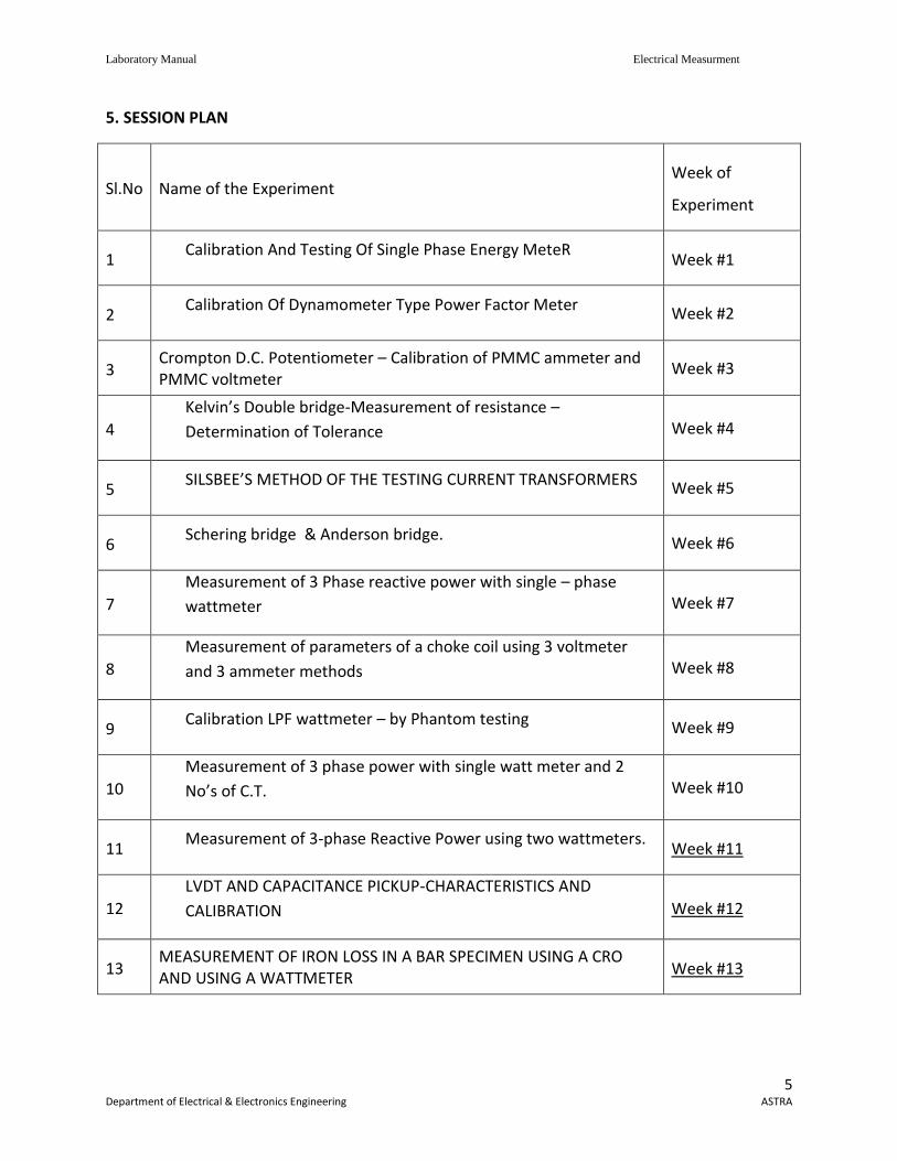
5. SESSION PLAN
Sl.No Name of the Experiment Week of
Experiment
1 Calibration And Testing Of Single Phase Energy MeteR
Week #1
2 Calibration Of Dynamometer Type Power Factor Meter
Week #2
3 Crompton D.C. Potentiometer – Calibration of PMMC ammeter and PMMC voltmeter
Week #3
4
Kelvin’s Double bridge-Measurement of resistance –
Determination of Tolerance Week #4
5 SILSBEE’S METHOD OF THE TESTING CURRENT TRANSFORMERS Week #5
6 Schering bridge & Anderson bridge.
Week #6
7
Measurement of 3 Phase reactive power with single – phase
wattmeter Week #7
8
Measurement of parameters of a choke coil using 3 voltmeter
and 3 ammeter methods Week #8
9 Calibration LPF wattmeter – by Phantom testing Week #9
10
Measurement of 3 phase power with single watt meter and 2
No’s of C.T. Week #10
11 Measurement of 3-phase Reactive Power using two wattmeters.
Week #11
12
LVDT AND CAPACITANCE PICKUP-CHARACTERISTICS AND
CALIBRATION Week #12
13 MEASUREMENT OF IRON LOSS IN A BAR SPECIMEN USING A CRO AND USING A WATTMETER
Week #13
Laboratory Manual Electrical Measurment
6 Department of Electrical & Electronics Engineering ASTRA
6. Experiment write up:
6.1. CALIBRATION AND TESTING OF SINGLE PHASE ENERGY METER AIM : To calibrate the given energy meter using a calinrated wattmeter. APPARATUS :
1. Variac, single phase, 10A 2. Voltmenter, 300 V AC 3. Ammeter, 0-10A, AC 4. Rheostar, - Lamp load 5. Wattmeter, LPF, 300 V, 10 A 6. Single phase energy meter
THEORY : The calibration of energy meter may become inaccurate during its vigorous use due to various reasons. It is necessary to calinrate the meter to determine the anount of error i.e. it’s reading so that same meter can be used for correct measurement of energy. In this method precision grade indicationg instruments are used as reference standard. These indicating instruments are connected in the circuit of meter under test. The current and voltages are held constant duting the test. The numbers of revolutions made by the test are recorded. The time taken is also measured. Energy recorded by meter under test = Rx / Kx – kWh. Energy computed from the readings of the indication instrument = kW x t Where Rx = number of revolutions made by disc of meter under test. Kx = number of revolutions per k Wh for meter under test. KW = Power in kilowatt as computed from readings watt meter indicating instruments t = time in hours.
Percentage Error = 100)/(
tkW
tkWKxRx
Before conducting any of these tests on a watt-meter its potential circuit must be connected to the supply for one hour in order to enable the self-heating of the potential coil to stabilize.
Laboratory Manual Electrical Measurment
7 Department of Electrical & Electronics Engineering ASTRA
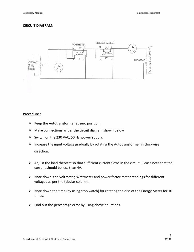
CIRCUIT DIAGRAM:
Precedure :
Keep the Autotransformer at zero position.
Make connections as per the circuit diagram shown below
Switch on the 230 VAC, 50 Hz, power supply.
Increase the input voltage gradually by rotating the Autotransformer in clockwise
direction.
Adjust the load rheostat so that sufficient current flows in the circuit. Please note that the
current should be less than 4A.
Note down the Voltmeter, Wattmeter and power factor meter readings for different voltages as per the tabular column.
Note down the time (by using stop watch) for rotating the disc of the Energy Meter for 10
times.
Find out the percentage error by using above equations.
Laboratory Manual Electrical Measurment
8 Department of Electrical & Electronics Engineering ASTRA
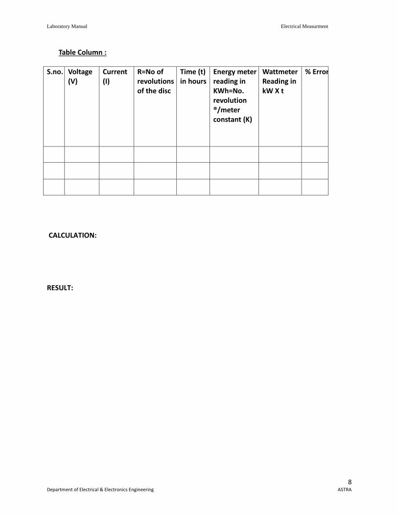
Table Column :
S.no. Voltage (V)
Current (I)
R=No of revolutions of the disc
Time (t) in hours
Energy meter reading in KWh=No. revolution ®/meter constant (K)
Wattmeter Reading in kW X t
% Error
CALCULATION:
RESULT:
Laboratory Manual Electrical Measurment
9 Department of Electrical & Electronics Engineering ASTRA
6.2. CALIBRATION OF DYNAMOMETER TYPE POWER FACTOR METER AIM : To calibrate a given single phase power factor meter. Apparatus :
1. Variac, single phase, 10A
2. Voltmeter, 300V AC
3. Ammeter, 0-10A, AC
4. Rheostat
5. Wattmeter, LPF, 300V, 10A
6. Dynamometer type power factor meter
Theory : The error made by the Power factor meter can be calculated by noting down the readings of various meters and error can be calculated by using formula Actual reading = Power factor meter reading
Single percentage of error = Actual reading – T reading X 100 Theoretical reading
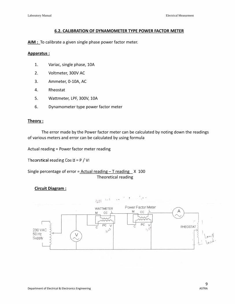
Circuit Diagram :
Laboratory Manual Electrical Measurment
10 Department of Electrical & Electronics Engineering ASTRA
Procedure :
Keep the Auto transformer at Zero position
Make connections as per Circuit diagram shown below.
Switch on the 230 VAC, 50 Hz, Power supply.
Increase the input voltage gradually by rotating the auto transformer in clockwise direction 220V.
Adjust the load rheostat so that sufficient current flows in the circuit, Please note that the current should be less then 4A.
Note down the Voltmeter, Ammeter, Wattmeter and power factor meter readings for different voltage as per the tabular column.
Find out the percentage error by using above equations.
Tabular Column :
S.no. V AC I AC Wattmeter reading
Power Factor meter Reading
% Error
CALCULATION:
RESULT:
Laboratory Manual Electrical Measurment
11 Department of Electrical & Electronics Engineering ASTRA
6.3 Cromption DC Potentiometer
Aim : To calibrate the D.C. crompton’s Potentiometer by calibration of voltmeter & ammeter
method.
Apparatus:
Cromption’s D.C. potentiometer circuit
Theory :
Standardization of cropmton D.C. potentiometer:
A practical form of D.C. potentiometer which is very widely used in crompton potentiometer.
A standard westen cell is connected across terminals are standardization circuit the battery
whose e.m.f. is to be measured is connected across terminals E1 & E2 with regard to polarity. T
He sliding contact E2 is set & the key ‘K’ is closed & null deflection is obtained by adjusting
resistances course & fine Rheostats. The change over switch position, if the battery whose
positions is to be measured to get balanced or null deflection.
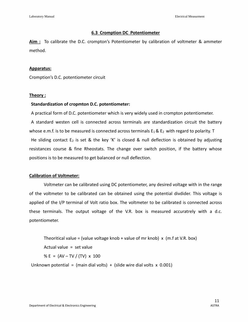
Calibration of Voltmeter:
Voltmeter can be calibrated using DC potentiometer, any desired voltage with in the range
of the voltmeter to be calibrated can be obtained using the potential divdider. This voltage is
applied of the I/P terminal of Volt ratio box. The voltmeter to be calibrated is connected across
these terminals. The output voltage of the V.R. box is measured accuratrely with a d.c.
potentiometer.
Theoritical value = (value voltage knob + value of mr knob) x (m.f at V.R. box)
Actual value = set value
% E = (AV – TV / (TV) x 100
Unknown potential = (main dial volts) + (slide wire dial volts x 0.001)
Laboratory Manual Electrical Measurment
12 Department of Electrical & Electronics Engineering ASTRA
Circuit Diagram:

Laboratory Manual Electrical Measurment
13 Department of Electrical & Electronics Engineering ASTRA
Procedure:
Standard of crompton D.C. potentiometer
1. D.C. potentiometer are used to calibrate voltmeter & ammeter.
2. A 2VDC supply is given to D.C. potentiometer
3. This can be achieved by standrdised the giving D.C. potentiometer with the help of
standard cell.
4. The connections are made as per the circuit diagram (A) placing shunt key at standard
mode.
5. By adjusting course and time rheostat we observe the zero deflection in galvanometer
If galvanometer shows zero deflection we can conclude that D.C. potentiometer is standrdised.
Calibration of Voltmeter:
1. Connect the circuit as per the circuit diagram.
2. Keep the function key on mode either E1 to E2
3. Set the voltage level so as to calibrate with crompton D.C. potentiometer.
4. By adjusting voltage knob & millivolts knob for zero deflection in the galvanometer.
5. Note down the readings by observing the p as of both knobs
6. Calculate theoretical value by considering multiplication factor from the voltratio box.
7. & Error = (Actual value – Theoretical value) / (Theoretical value) x 100
Theoretical value = (Value at voltage at knob + value at mv knob) x (m.f. at V-r knob)
Actual value = set value.
Laboratory Manual Electrical Measurment
14 Department of Electrical & Electronics Engineering ASTRA
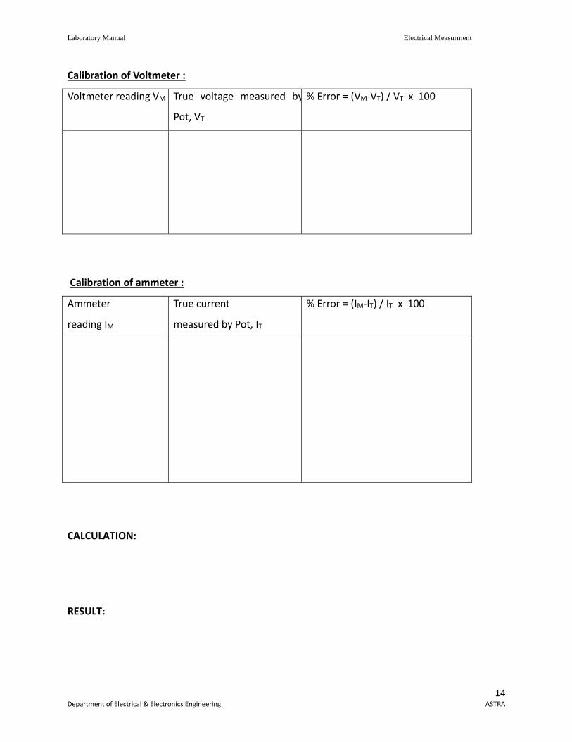
Calibration of Voltmeter :
Voltmeter reading VM True voltage measured by
Pot, VT
% Error = (VM-VT) / VT x 100
Calibration of ammeter :
Ammeter
reading IM
True current
measured by Pot, IT
% Error = (IM-IT) / IT x 100
CALCULATION:
RESULT:
Laboratory Manual Electrical Measurment
15 Department of Electrical & Electronics Engineering ASTRA
6.4. KELVINS DOUBLE BRIDGE
AIM : To determine the resistance using Kelvins double bridge. Apparatus : Main dial : 100 divisions of side wire are equal to 0.1 Ohms. Each main division is equal to
0.001 ohm. Each sub – division is equal to 0.0005 ohm. The readings to the left of zero is to be
subtracted from the main dial readings & that of the right of zero is to be added to main dial
reading.
Range switch : arrange multiplier witch furnishers 5 ranges of X 100, X 10, XZI & X 0.001. The
value of unknown resistance is given by sum of main dial & slide wire reading multiplied by range
used.
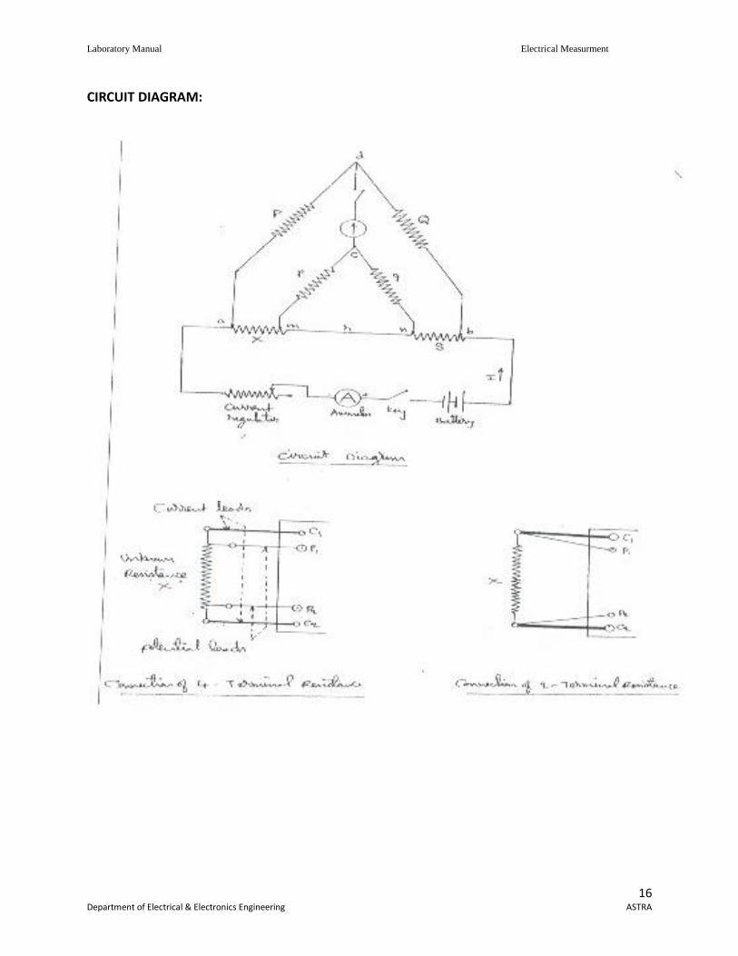
Theory :
The kelvins bridge is a modification of the wheat stone bridge & provides greatly
increased accuracy in measurement of low resistances.
Kelvins Bridge is show in the figure where ‘r’ represents resistance of the lead that connects the
unknown resistances ‘R’ to standard resistance ‘s’ Tow galvanometer connections may ne either
to point ‘m’ or point ‘m’ the resistance ‘r’ of the connecting leads is added to standard resistance
resulting in indication of too low an indication of unknown resistance R. When the connection is
made to pint ‘n’ the resistance r, is added to unknown resistance resulting in indication of too
high a value of ‘R’.
Laboratory Manual Electrical Measurment
16 Department of Electrical & Electronics Engineering ASTRA
CIRCUIT DIAGRAM:
Laboratory Manual Electrical Measurment
17 Department of Electrical & Electronics Engineering ASTRA
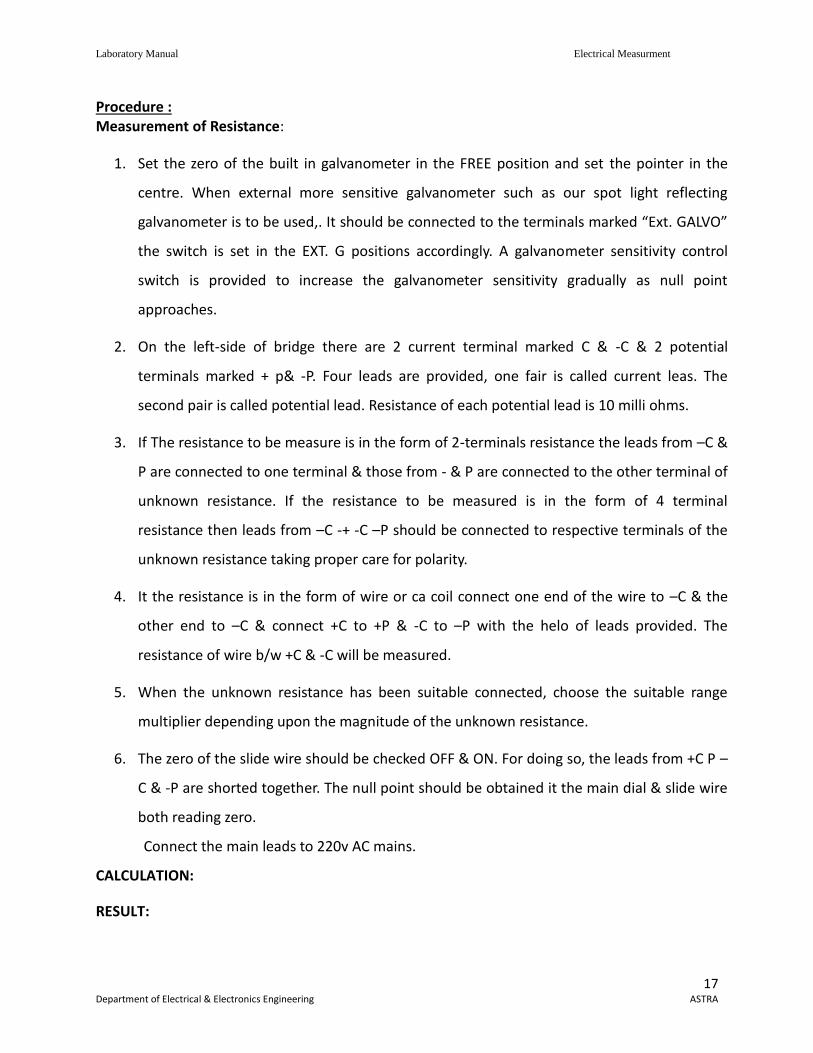
Procedure : Measurement of Resistance:
1. Set the zero of the built in galvanometer in the FREE position and set the pointer in the
centre. When external more sensitive galvanometer such as our spot light reflecting
galvanometer is to be used,. It should be connected to the terminals marked “Ext. GALVO”
the switch is set in the EXT. G positions accordingly. A galvanometer sensitivity control
switch is provided to increase the galvanometer sensitivity gradually as null point
approaches.
2. On the left-side of bridge there are 2 current terminal marked C & -C & 2 potential
terminals marked + p& -P. Four leads are provided, one fair is called current leas. The
second pair is called potential lead. Resistance of each potential lead is 10 milli ohms.
3. If The resistance to be measure is in the form of 2-terminals resistance the leads from –C &
P are connected to one terminal & those from - & P are connected to the other terminal of
unknown resistance. If the resistance to be measured is in the form of 4 terminal
resistance then leads from –C -+ -C –P should be connected to respective terminals of the
unknown resistance taking proper care for polarity.
4. It the resistance is in the form of wire or ca coil connect one end of the wire to –C & the
other end to –C & connect +C to +P & -C to –P with the helo of leads provided. The
resistance of wire b/w +C & -C will be measured.
5. When the unknown resistance has been suitable connected, choose the suitable range
multiplier depending upon the magnitude of the unknown resistance.
6. The zero of the slide wire should be checked OFF & ON. For doing so, the leads from +C P –
C & -P are shorted together. The null point should be obtained it the main dial & slide wire
both reading zero.
Connect the main leads to 220v AC mains.
CALCULATION:
RESULT:
Laboratory Manual Electrical Measurment
18 Department of Electrical & Electronics Engineering ASTRA
6.5. SILSBEE’S METHOD OF THE TESTING CURRENT TRANSFORMERS
AIM ; To determine the percentage ration error and the phase angle of the given current
transformer by comparison with another current transformer whose error are known.
Apparatus :
Standard CT (one for which the error are known)
Testing CT
Wattmeter, LPF – 2 Nos
Ammeter (MI type) 2-Nos
Rheostat
Phase shifting transformer
Theory :
This is a comparison type of test employing defect ional methods. Here the ratio and
phase angle of the test transformer X are determined in terms of that of a standard transformer
shaving same nominal ration.
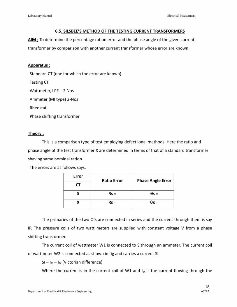
The errors are as follows says:
Error Ratio Error Phase Angle Error
CT
S Rs = θs =
X Rs = θx =
The primaries of the two CTs are connected in series and the current through them is say
IP. The pressure coils of two watt meters are supplied with constant voltage V from a phase
shifting transformer.
The current coil of wattmeter W1 is connected to S through an ammeter. The current coil
of wattmeter W2 is connected as shown in fig and carries a current SI.
SI – Iss – Isx (Victorian difference)
Where the current is in the current coil of W1 and Isx is the current flowing through the
Laboratory Manual Electrical Measurment
19 Department of Electrical & Electronics Engineering ASTRA
burden. The phase shifting transformer is adjusted so that the wattmeter W1 reads zero.
W 1q = V peq Iss Cos 90 = θ
W 1q = V peq SI cos (θx- θs)
=V Isx sin (θx- θs)
Where Vpeq is the voltage from the phase shifting transformer, which is in quadrature with the Iss
in is current coil of W1.
Then the phase of the voltage from the phase shifting transformer is shifted through 90o
Therefore, now V is phase with the current Iss.
W1p = V Iss
W 2p = VSI sin (θx – θs)
= V (Iss – Isx cos (θx – θs)
= Wip = Visx cos (θx – θs)
As (θx – θs)~0
Therefore Visx = W 10 W2p
Rx = Ip/Isx
Rs = Ip / Isx
ppWW
pW
VI
VI
I
I
R
R
SX
SS
SX
SS
s
x
21
1
Ratio error Rx = Rs
pW
pW
1
21
Now to obtain the phase Angle Errors
Sin (θx – θs) = W2q / VIsx
Cos (θx – θs) = (Wp – W2p) / V Isx
Tan (θx – θs) = W2q / (W1p – W2p)
OR
Phase angle error θx = W2q / (W1p – W2p)
Phase angle error θx = W2q / (W1p – W2p) + θs
Laboratory Manual Electrical Measurment
20 Department of Electrical & Electronics Engineering ASTRA
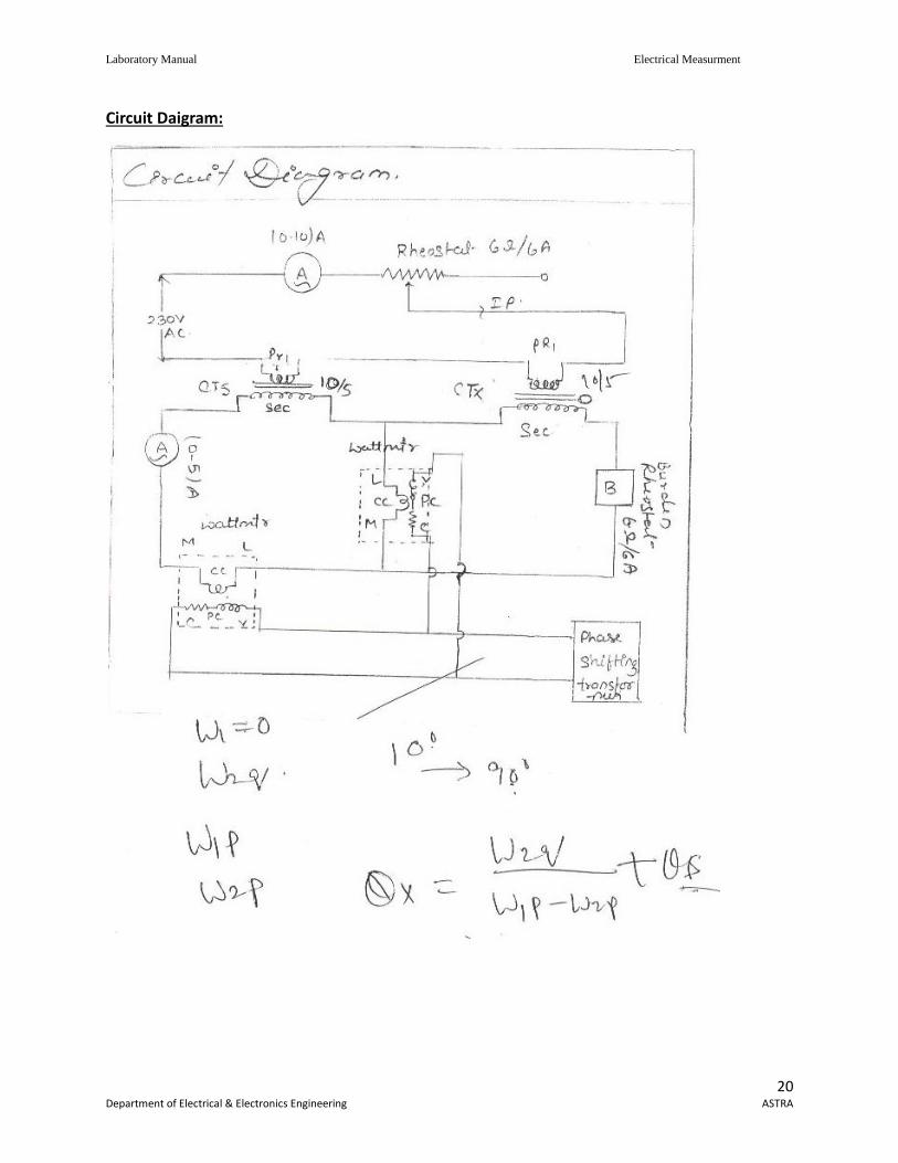
Circuit Daigram:
Laboratory Manual Electrical Measurment
21 Department of Electrical & Electronics Engineering ASTRA
Procedure :
The connections are made as per the circuit diagrm. The burden is adjusted to have a
suitable current in the phase angle is adjusted using the phase shifting transformer will
wattmeter W1 reads Zero.
Reading of the other wattmeter (w2q) is noted.
A phase shift of 90 is obtained by the phase shifting transformer. The two wattmeter
readings W 1p and W2p are then observed.
The ratio error is calculate ding the formula Rx = Rs
The phase angle error is calculated using the formula
The experiment is repeated by varying the curden and setting different values for Iss.
The average values of Rs and are then obtained.
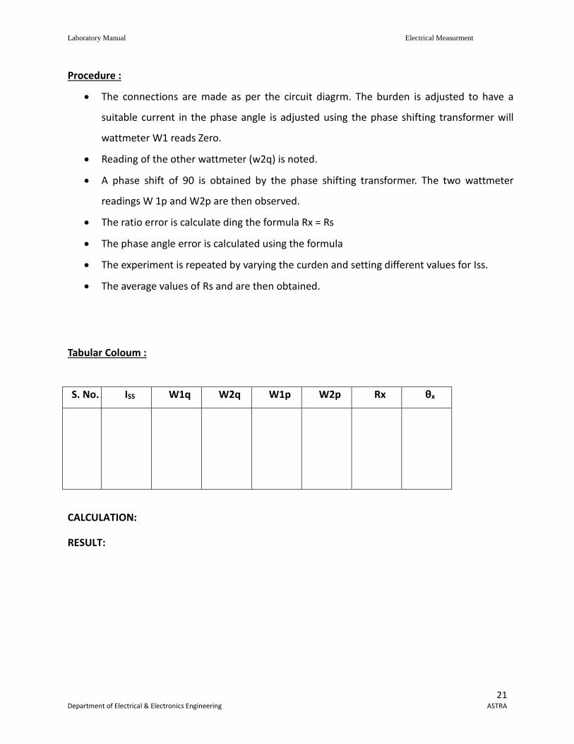
Tabular Coloum :
S. No. ISS W1q W2q W1p W2p Rx θx
CALCULATION:
RESULT:
Laboratory Manual Electrical Measurment
22 Department of Electrical & Electronics Engineering ASTRA
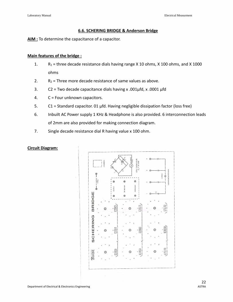
6.6. SCHERING BRIDGE & Anderson Bridge
AIM : To determine the capacitance of a capacitor.
Main features of the bridge :
1. R1 = three decade resistance dials having range X 10 ohms, X 100 ohms, and X 1000
ohms
2. R2 = Three more decade resistance of same values as above.
3. C2 = Two decade capacitance dials having x .001μfd, x .0001 μfd
4. C = Four unknown capacitors.
5. C1 = Standard capacitor. 01 μfd. Having negligible dissipation factor (loss free)
6. Inbuilt AC Power supply 1 KHz & Headphone is also provided. 6 interconnection leads
of 2mm are also provided for making connection diagram.
7. Single decade resistance dial R having value x 100 ohm.
Circuit Diagram:
Laboratory Manual Electrical Measurment
23 Department of Electrical & Electronics Engineering ASTRA
Laboratory Manual Electrical Measurment
24 Department of Electrical & Electronics Engineering ASTRA
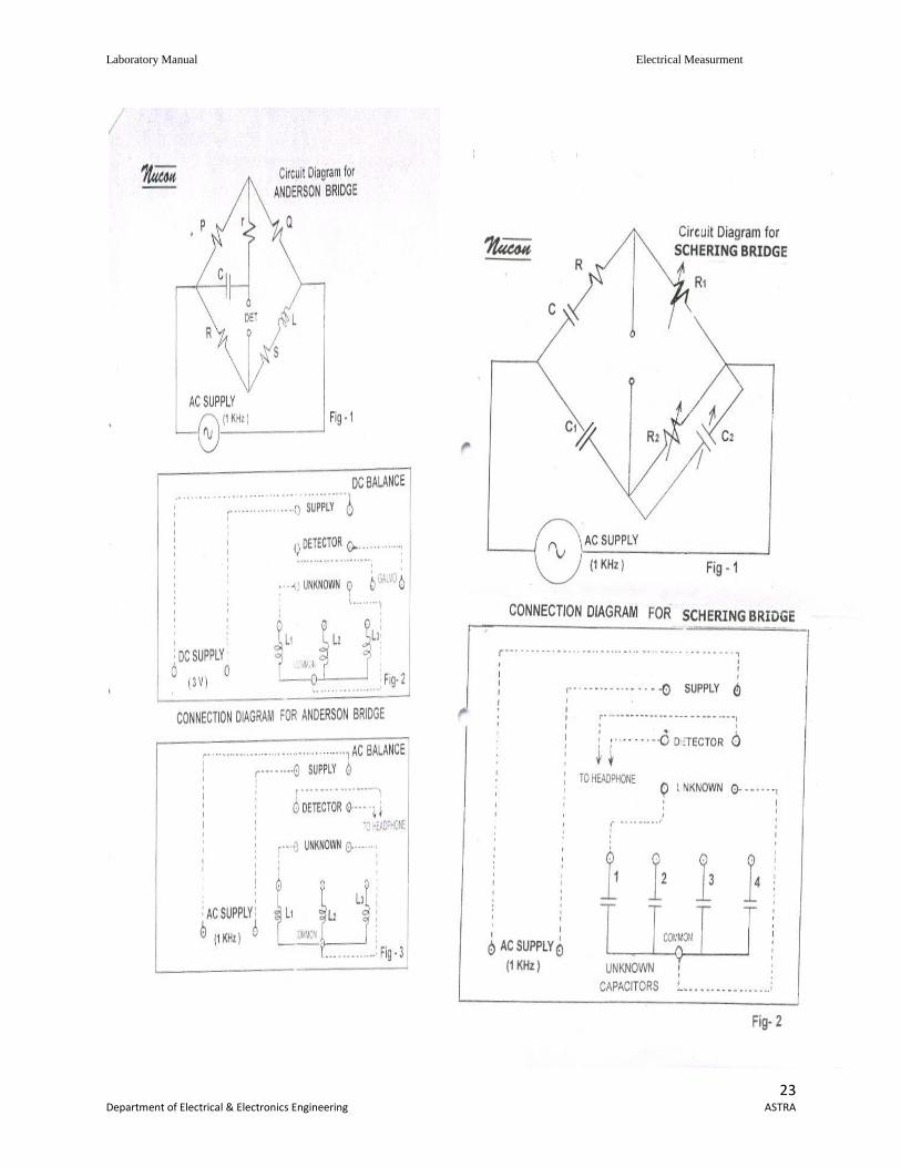
Procedure :
Make the connection as shown in fig. 2 using A.C. supply of frequency 1KHz & head
phone. Connect one unknown capacitor as shown in connection diagram set the capacitor dial C2
at zero position and R also at zero position. We have made connections internally as per circuit
diagram.
Now introduce some resistance from decade resistance dial R1 say 1000 ohms and adjust
the decade resistance dial R2 to minimize the sound in the head phone. With alternate
adjustment of decade resistance R1 and R2 we can get the minimum sound or no sound in the
headphone. Note the value of R1, R2 and C1. Calculate the value of unknown capacitor by using
formula given below.
1
11.
R
RCC
Repeat the experiment with different value of unknown capacitor.
Note the value of unknown capacitors:
C = 1 ………….. 0.01μfd 2. ………….. 0.02μfd
3 ………….. 0.01μfd 4 ………….. 0.02μfd
Additional Experiment:
To determine the dissipation factor of a capacitor.
Dissipation factor: It is also called power factor of a capacitor and it is a very good test of its
quality.
Dissipation factor D = CR
Where = 2 f
C = Capacitance of a capacitor
R = Series Resistance of a capacitor representing the
loss in the capacitor.
Laboratory Manual Electrical Measurment
25 Department of Electrical & Electronics Engineering ASTRA
Procedure:
Without disturbing the setting of the bridge
(i.e. Null point with R1 and R2)
Introduce some resistance say 500 ohms from resistance dial ‘R’. There will again be
some sound in the headphone. Now
Adjust the capacitance dial C2 to minimuse the sound in the using above formula. Repeat
the experiment with different value of resistance dial R.
Observation & Calculations:
Proceed as described above & note down various readings & Calculate value of
Capacitance & Dissipation factor. Match these values with the values of C as mentioned in last
page.
To determine the self Inductance for a coil by Andersonbridge.
Main Features Of the Bridge:
R ………… Three decade resistance dials having value from 1 ohm to 1 K
ohm
R ………. Three decade resistance dials having value for 10 ohm to 10 k
Ohm
C1 ……. Two fixed standard capacitors having values 0.1 μfd and 0.2 μfd
Pand Q ………. Fixed standard values of 1 K ohms each
S………. Single decade resistance dial having values from 0.1 ohm to 1
OHM
L ……… Three unknown inductance
In built Galvanometer for DC Null point, Head phone & AC supply provided. 6 interconnection
leads of 2mm are also provided for making connection diagram.
Laboratory Manual Electrical Measurment
26 Department of Electrical & Electronics Engineering ASTRA
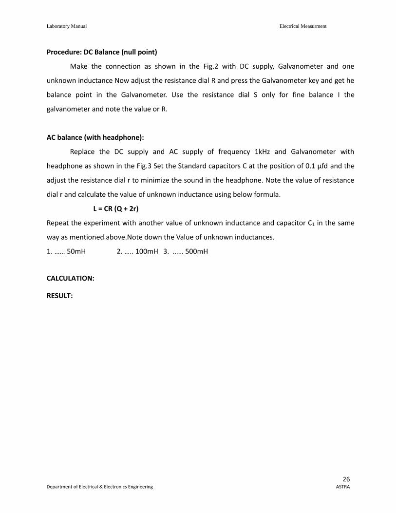
Procedure: DC Balance (null point)
Make the connection as shown in the Fig.2 with DC supply, Galvanometer and one
unknown inductance Now adjust the resistance dial R and press the Galvanometer key and get he
balance point in the Galvanometer. Use the resistance dial S only for fine balance I the
galvanometer and note the value or R.
AC balance (with headphone):
Replace the DC supply and AC supply of frequency 1kHz and Galvanometer with
headphone as shown in the Fig.3 Set the Standard capacitors C at the position of 0.1 μfd and the
adjust the resistance dial r to minimize the sound in the headphone. Note the value of resistance
dial r and calculate the value of unknown inductance using below formula.
L = CR (Q + 2r)
Repeat the experiment with another value of unknown inductance and capacitor C1 in the same
way as mentioned above.Note down the Value of unknown inductances.
1. …… 50mH 2. ….. 100mH 3. …… 500mH
CALCULATION:
RESULT:
Laboratory Manual Electrical Measurment
27 Department of Electrical & Electronics Engineering ASTRA
6.7. MEASUREMETN OF 3-PHASE REACTIVE POWER USING SINGLE WATTMETER
AIM : To measure 3-phase reactive power using single phase wattmeter
APPARATUS :
1. single phase wattmeter -1 No
2. three phase inductive load
Theory :
Three phase reactive power can be measured by two wattmeter method which is
universally adopted method. The difference between higher readings wattmeter and lower
wattmeter readings yields. VL IL L IL
Reactive power in a balance 3-
this method. The current coil of the wattmeter is connected in any on line and the pressure coils
across the other two lines. Let us assume that the current could is connected in R phase and
pressure coil is connected across ‘Y’ and ‘B’ phases. Assuming phase. Assuming phase sequence
Here current through current coil = IR
Voltage across pressure coil = VYB
The single phase between VYB and IR from the phase diagram 900-
Wattmeter reading is VYB IR cos (900-
W =VYB IR Sin (-
In terms of line current and voltage
W = VYB IR cos (900-
Terms of line current and voltage
W = VLIL
The total 3- LIL
Laboratory Manual Electrical Measurment
28 Department of Electrical & Electronics Engineering ASTRA
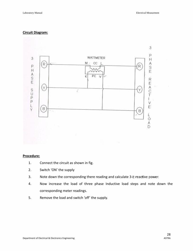
Circuit Diagram:
Procedure:
1. Connect the circuit as shown in fig.
2. Switch ‘ON’ the supply
3. Note down the corresponding there reading and calculate 3-
4. Now increase the load of three phase Inductive load steps and note down the
corresponding meter readings.
5. Remove the load and switch ‘off’ the supply.
Laboratory Manual Electrical Measurment
29 Department of Electrical & Electronics Engineering ASTRA
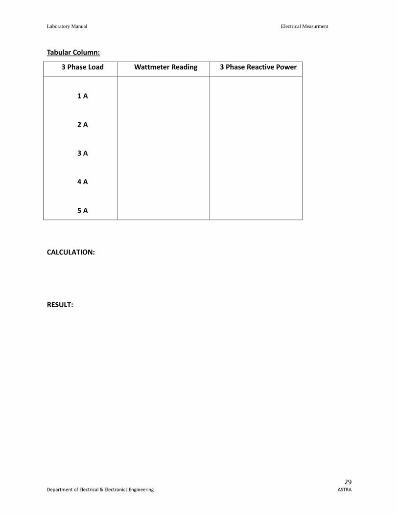
Tabular Column:
3 Phase Load Wattmeter Reading 3 Phase Reactive Power
1 A
2 A
3 A
4 A
5 A
CALCULATION:
RESULT:
Laboratory Manual Electrical Measurment
30 Department of Electrical & Electronics Engineering ASTRA
6.8. 3AMMETERS AND 3 VOLTEMETRS METHOD
AIM: To measure the inductance and power factor of the choke coil using 3 Ammeter and 3
Voltmeter method.
Apparatus:
1. Ammeter 0-5A, -3 No’s
2. Voltmeters 0-300V -3 No’s
3. Resistor
4. Choke coil
5. Auto transformer
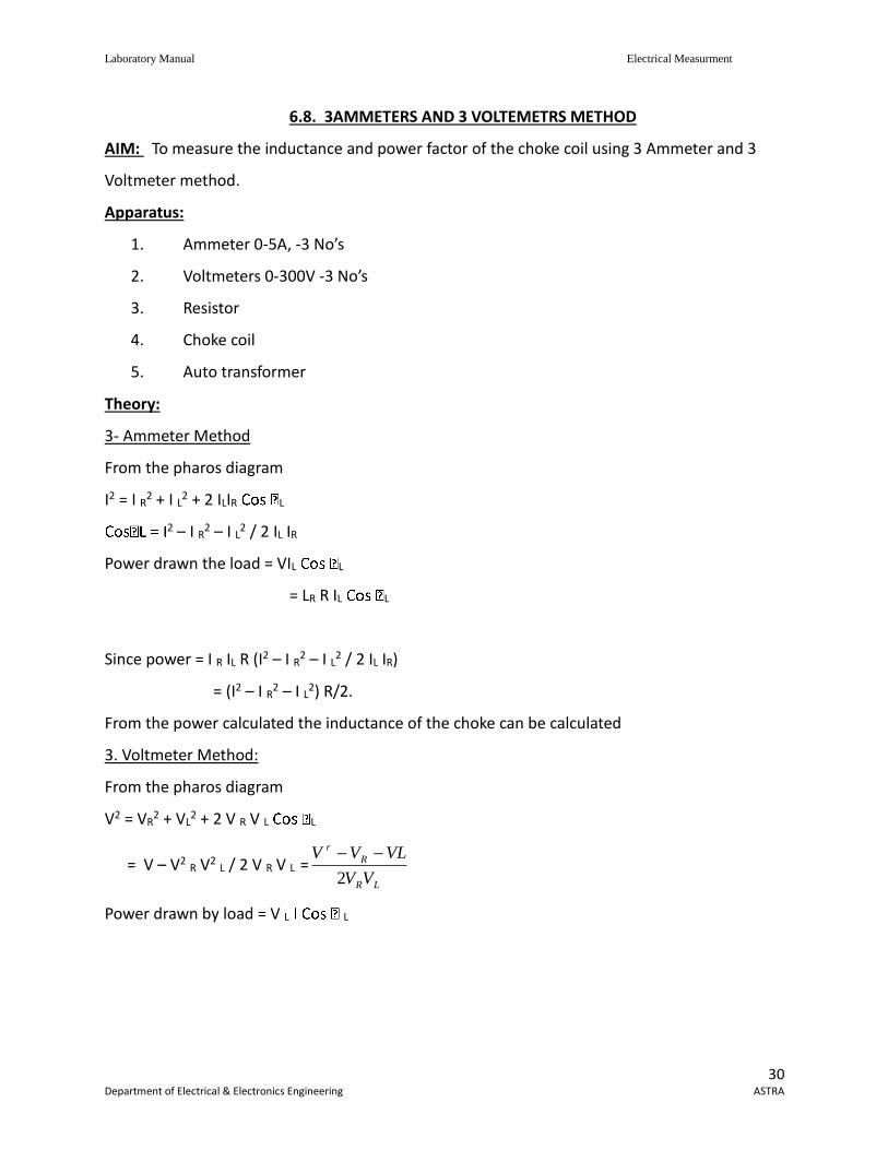
Theory:
3- Ammeter Method
From the pharos diagram
I2 = I R2 + I L2 + 2 ILIR L
2 – I R2 – I L2 / 2 IL IR
Power drawn the load = VIL L
= LR R IL L
Since power = I R IL R (I2 – I R2 – I L2 / 2 IL IR)
= (I2 – I R2 – I L2) R/2.
From the power calculated the inductance of the choke can be calculated
3. Voltmeter Method:
From the pharos diagram
V2 = VR2 + VL
2 + 2 V R V L L
= V – V2 R V2 L / 2 V R V L =LR
R
r
VV
VLVV
2
Power drawn by load = V L L
Laboratory Manual Electrical Measurment
31 Department of Electrical & Electronics Engineering ASTRA
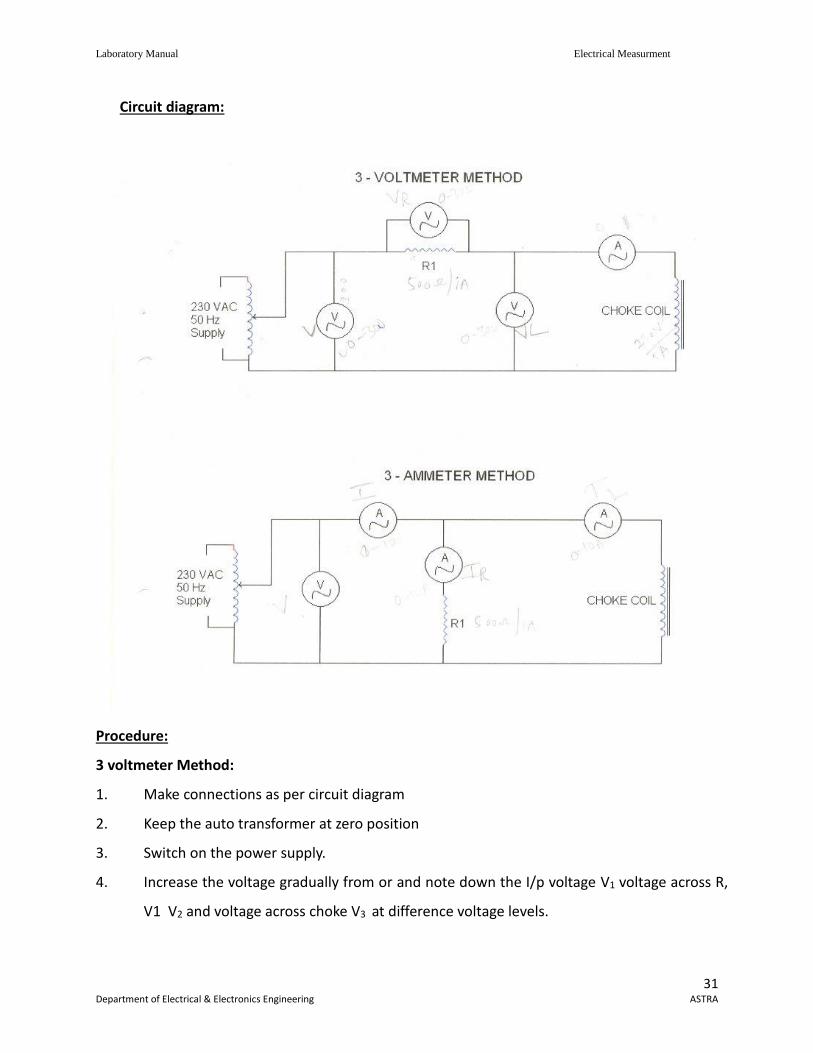
Circuit diagram:
Procedure:
3 voltmeter Method:
1. Make connections as per circuit diagram
2. Keep the auto transformer at zero position
3. Switch on the power supply.
4. Increase the voltage gradually from or and note down the I/p voltage V1 voltage across R,
V1 V2 and voltage across choke V3 at difference voltage levels.
Laboratory Manual Electrical Measurment
32 Department of Electrical & Electronics Engineering ASTRA
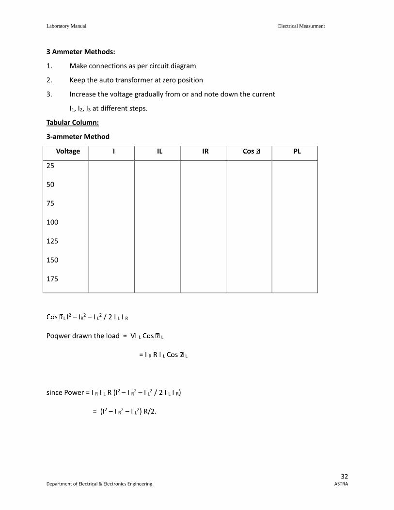
3 Ammeter Methods:
1. Make connections as per circuit diagram
2. Keep the auto transformer at zero position
3. Increase the voltage gradually from or and note down the current
I1, I2, I3 at different steps.
Tabular Column:
3-ammeter Method
Voltage I IL IR PL
25
50
75
100
125
150
175
L I2 – IR2 – I L2 / 2 I L I R
Poqwer drawn the load = VI L L
= I R R I L L
since Power = I R I L R (I2 – I R2 – I L2 / 2 I L I R)
= (I2 – I R2 – I L2) R/2.
Laboratory Manual Electrical Measurment
33 Department of Electrical & Electronics Engineering ASTRA
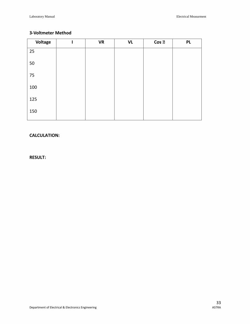
3-Voltmeter Method
Voltage I VR VL PL
25
50
75
100
125
150
CALCULATION:
RESULT:
Laboratory Manual Electrical Measurment
34 Department of Electrical & Electronics Engineering ASTRA
6.9. CALIBRATION OF LPF WATTMETER BY PHANTOM LOADING
AIM ; To calibrate LPF wattmeter by phantom loading.
Apparatus Required:
1. Voltmeter, 300 V AC
2. Ammeter, 0-10A
3. Variac, Single phase, 10A
4. Rheostat
5. LPF Wattmeter
6. Power Factor Meter
Theory:
When the current rating of a meter test is high a test with loading arrangements would
involve a considerable waste of power. In order to avoid this “phantom” or “Fictitious” loading is
done. Phantom loading consists of supplying the pressure circit from a circuit from a circuit of
required normal voltage, and the current from a separate low voltage supply as the impedance of
this circuit very low. With this arrangement the total power supplied for the test is that due to the
small pressure coil current at normal voltage, Plus that due to the current circuit current supplied
at low voltage. The total powe, therefore, required for testing the meter with phantom loading is
comparatively very small.
Wattmeter reading = Actual reading
Theoretical reading P = V
P = Voltmeter reading X Ammeter reading X Power factor reading
Actual Reading – Theoretical Reading
% Error = ----------------------------------------------------------- X 100
Theoretical Reading
Laboratory Manual Electrical Measurment
35 Department of Electrical & Electronics Engineering ASTRA
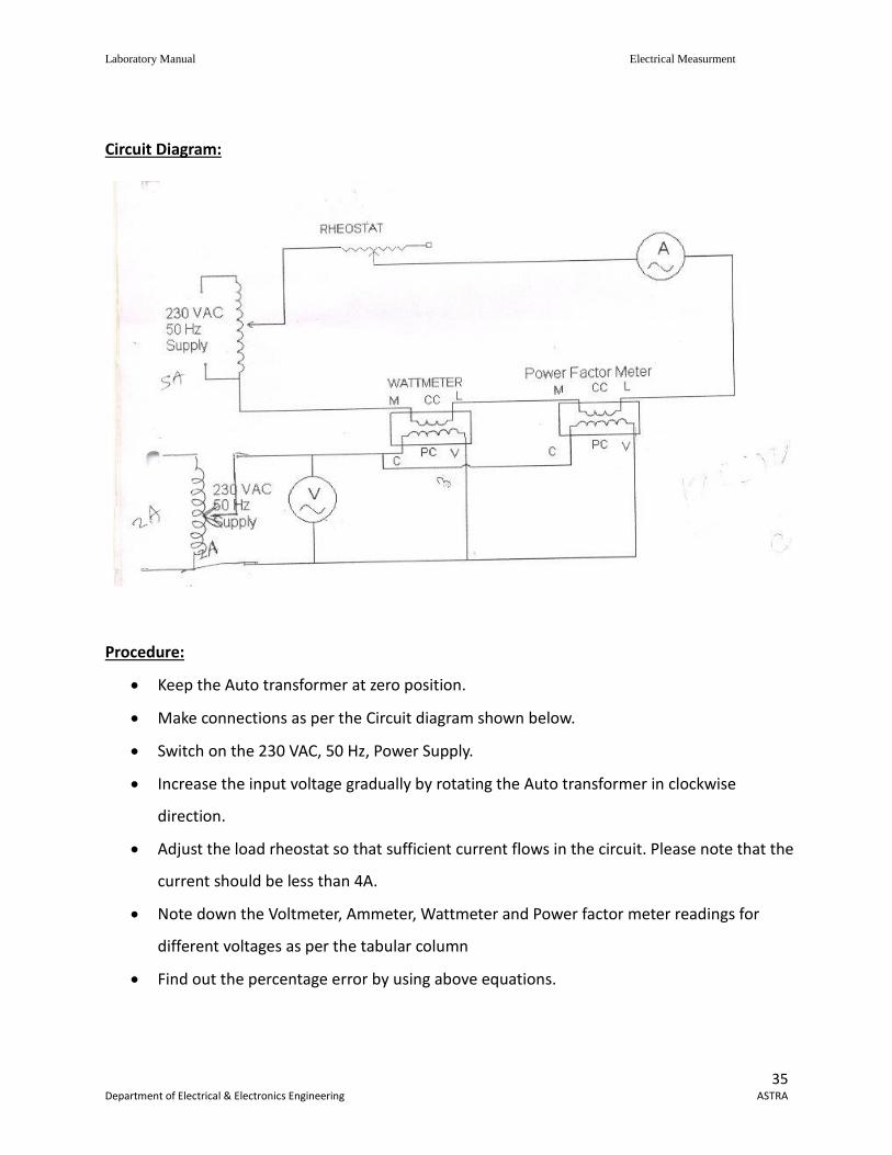
Circuit Diagram:
Procedure:
Keep the Auto transformer at zero position.
Make connections as per the Circuit diagram shown below.
Switch on the 230 VAC, 50 Hz, Power Supply.
Increase the input voltage gradually by rotating the Auto transformer in clockwise
direction.
Adjust the load rheostat so that sufficient current flows in the circuit. Please note that the
current should be less than 4A.
Note down the Voltmeter, Ammeter, Wattmeter and Power factor meter readings for
different voltages as per the tabular column
Find out the percentage error by using above equations.
Laboratory Manual Electrical Measurment
36 Department of Electrical & Electronics Engineering ASTRA
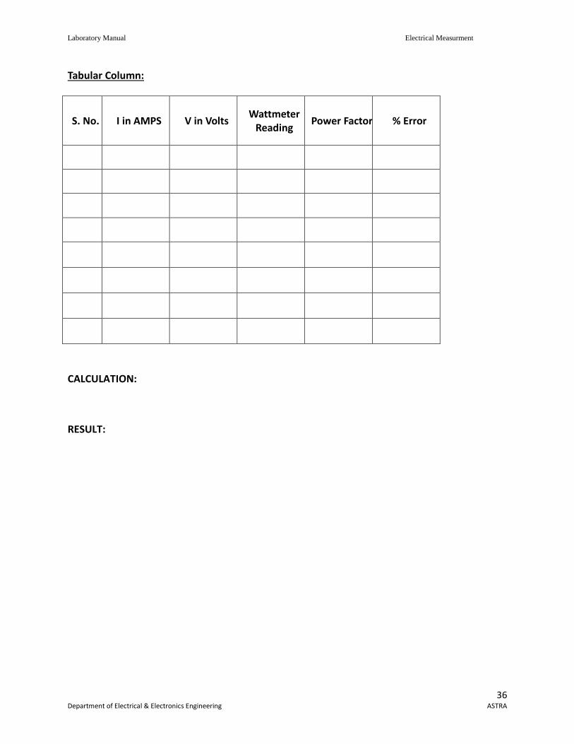
Tabular Column:
S. No. I in AMPS V in Volts Wattmeter
Reading Power Factor % Error
CALCULATION:
RESULT:
Laboratory Manual Electrical Measurment
37 Department of Electrical & Electronics Engineering ASTRA
6.10. MEASUREMENT OF 3 PHASE APOWER WITH SINGLE WATT METER AND 2 NOS OF CURRENT TRANSFORMERS
AIM : To measurement of 3 phase power with single watt meter and 2 nos of current transformers. Apparatus:
1. Wattmeter, LPF, 300V 10A 2. Current transformers – 2 No’s
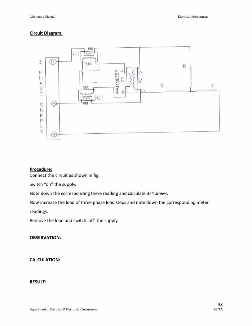
Theory : This method makes of two current transformers of ratio 1:1 to add the phase currents
from two phases in the current coil of the wattmeter. The connections are shown in the figure.
The potential coil of wattmeter is connected across the some phases.
Voltage across potential coil circuit of wattmer V13 = V1 – V2 = √3 VP Current through current coil of wattmeter I = I1 – I2 = √3IP
Since each of the two vectors is displaced 30o in same direction from the corresponding phase vector so that their phase difference phase is equal to the load power factor angle. Since power measured by wattmeter √3 VP VIP p I p
Laboratory Manual Electrical Measurment
38 Department of Electrical & Electronics Engineering ASTRA
Circuit Diagram:
Procedure: Connect the circuit as shown in fig.
Switch “on” the supply.
Note down the corresponding there reading and calculate 3-
Now increase the load of three phase load steps and note down the corresponding meter
readings.
Remove the load and switch ‘off’ the supply.
OBSERVATION:
CALCULATION:
RESULT:
Laboratory Manual Electrical Measurment
39 Department of Electrical & Electronics Engineering ASTRA
6.11. MEASUREMENT OF 3-PHASE REACTIVE POWER USING TWO WATTMETER AIM : The measure 3-phase power using two wattmeter Apparatus :
1. Single phase wattmeter – 2 Nos 2. Three Phase Resistive Load
Theory: Three phase reactive power can be measured by two wattmeter method which is
universally adopted method. The difference between higher reading wattmeter and low
wattmeter readings yiels = ds V1. I1 1. I1
Reactive power in a balance 3-
this method, the current coil of wattmeter is connected in any on line and the pressure coiled
across the other two lines. Let us assume that the current coil is connected in R phase and
pressure coil is connected across ‘Y’ and ‘B’ phase,. Assuming phases. Assuming phase sequence
RYB and an indicative load of an angle the phsor diagram for the circuits is as follows.
Here current through current coil = IR.
Voltage across pressure coil = VYB.
The current through wattmeter P1 is I and a voltage across its pressure coil is VI leads V by an
angle (30-
Readings of P1 wattmeter, P = VI cos (30-
The current through wattmeter P2 is I and voltages across its pressure coil is VI lags V by an angle
Sum of reading of two wattmeters
P1 + P2 = √3 VI [cos (30 - -
Laboratory Manual Electrical Measurment
40 Department of Electrical & Electronics Engineering ASTRA
Difference of readings of two wattmeters
P1 – P2 = √3 VI [cos (30- -
3
tan
3
3
21
21
VICos
VISin
PP
PP - √3
21
21
PP
PP
- √321
21
PP
PP
Current through the current coil = I
Voltage across the pressured coil = V
-√3 * readings of wattmeter
– Q/P
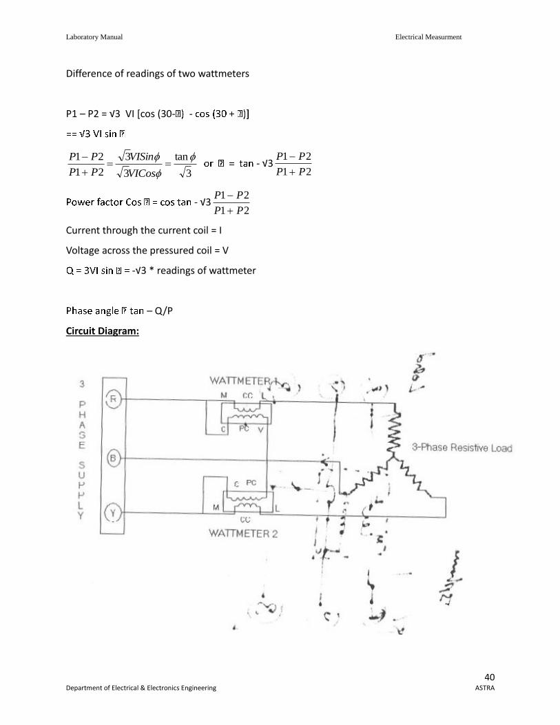
Circuit Diagram:
Laboratory Manual Electrical Measurment
41 Department of Electrical & Electronics Engineering ASTRA
Procedure:
1. connect the circuit as shown in fig.
2. Switch ‘ON’ the supply.
3. Note down the corresponding there reading and calculate 3-
4. Now increase the load of three phase inductive load steps and note down the
corresponding meter readings.
5. Remove the load and switching ‘off’ the supply.
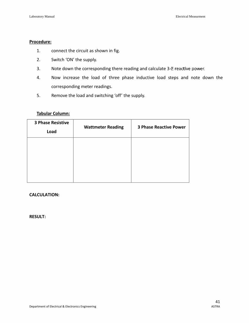
Tabular Column:
3 Phase Resistive
Load Wattmeter Reading 3 Phase Reactive Power
CALCULATION:
RESULT:
Laboratory Manual Electrical Measurment
42 Department of Electrical & Electronics Engineering ASTRA
6.12 LVDT AND CAPACITANCE PICKUP-CHARACTERISTICS AND CALIBRATION
AIM: To measure the displacement using linear variable differential transformer. APPARATUS:.
THEORY: Linear variable differential transformer LVDT is a transducer. Basically it is passive inductive
transformer similar to a potential transformer.LVDT consists of three windings, one primary and
two secondaries of equal turns. Primary is woundcentrally between two secondaries. All three
windings are wound on a hollow tubular former throughwhich magnetic core slides.Core affects
magnetic coupling between primary and the secondaries while primary is connected to an
ACsignal.Normal / null position of core causes equal induced voltage in both the secondaries.
Hence the totaldifference voltage of both the secondaries becomes zero. Any deviation in core
position from its nullposition induces unequal voltage from both secondaries and hence the
difference signal of it is a non zeroquantity, this non zero quantity varies withcore position.
Ideally displacement versus change in differencesignal should be linear.When ES1=ES2 (core at
null position or central position)Ediff=0When core is moved left
ES1>ES2 & Ediff (ES1-ES2) is in phase with ES1 When core is moved right ES1<ES2 Ediff (ES1-ES2) is in phase with ES2. Amount of Ediff. is proportional to the displacement of core. Phase angle of the output voltage
decides thedirection of core from its normal null position.Electronic circuit can be used to
Laboratory Manual Electrical Measurment
43 Department of Electrical & Electronics Engineering ASTRA
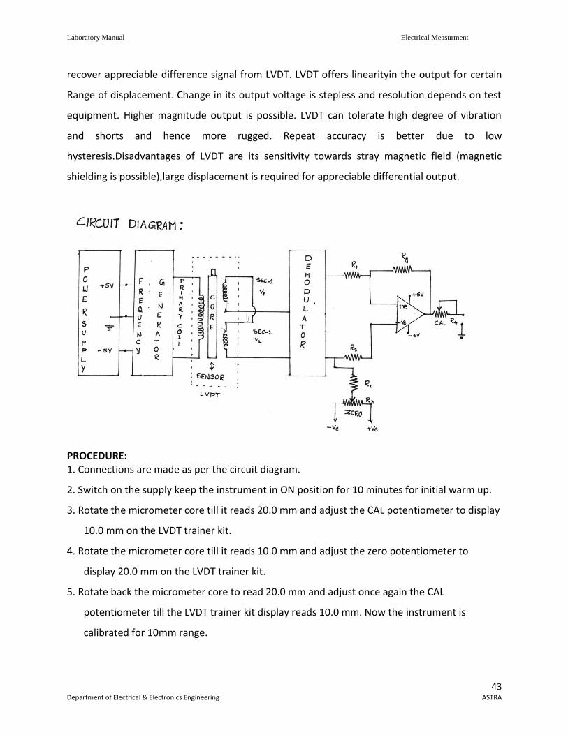
recover appreciable difference signal from LVDT. LVDT offers linearityin the output for certain
Range of displacement. Change in its output voltage is stepless and resolution depends on test
equipment. Higher magnitude output is possible. LVDT can tolerate high degree of vibration
and shorts and hence more rugged. Repeat accuracy is better due to low
hysteresis.Disadvantages of LVDT are its sensitivity towards stray magnetic field (magnetic
shielding is possible),large displacement is required for appreciable differential output.
PROCEDURE: 1. Connections are made as per the circuit diagram.
2. Switch on the supply keep the instrument in ON position for 10 minutes for initial warm up.
3. Rotate the micrometer core till it reads 20.0 mm and adjust the CAL potentiometer to display
10.0 mm on the LVDT trainer kit.
4. Rotate the micrometer core till it reads 10.0 mm and adjust the zero potentiometer to
display 20.0 mm on the LVDT trainer kit.
5. Rotate back the micrometer core to read 20.0 mm and adjust once again the CAL
potentiometer till the LVDT trainer kit display reads 10.0 mm. Now the instrument is
calibrated for 10mm range.
Laboratory Manual Electrical Measurment
44 Department of Electrical & Electronics Engineering ASTRA
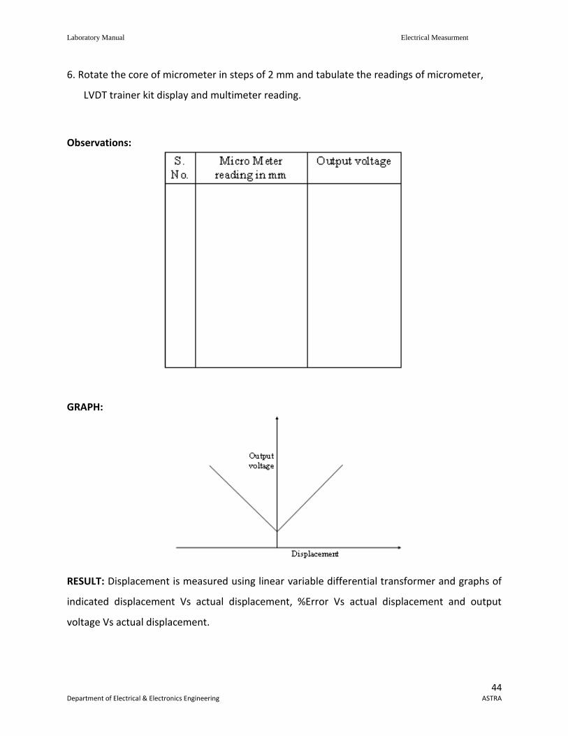
6. Rotate the core of micrometer in steps of 2 mm and tabulate the readings of micrometer,
LVDT trainer kit display and multimeter reading.
Observations:
GRAPH:
RESULT: Displacement is measured using linear variable differential transformer and graphs of
indicated displacement Vs actual displacement, %Error Vs actual displacement and output
voltage Vs actual displacement.
Laboratory Manual Electrical Measurment
45 Department of Electrical & Electronics Engineering ASTRA
6.13 MEASUREMENT OF IRON LOSS IN A BAR SPECIMEN USING A CRO AND USING A
WATTMETER
AIM: To measure the iron losses in strip (sheet) material using Lloyd - Fisher Square. APPARATUS:
THEORY: The voltage across the secondary i.e. voltmeter reading given the rms value of the induced voltage. E = 4 kfm f N2 N2 = No. of turn of the secondary winding.
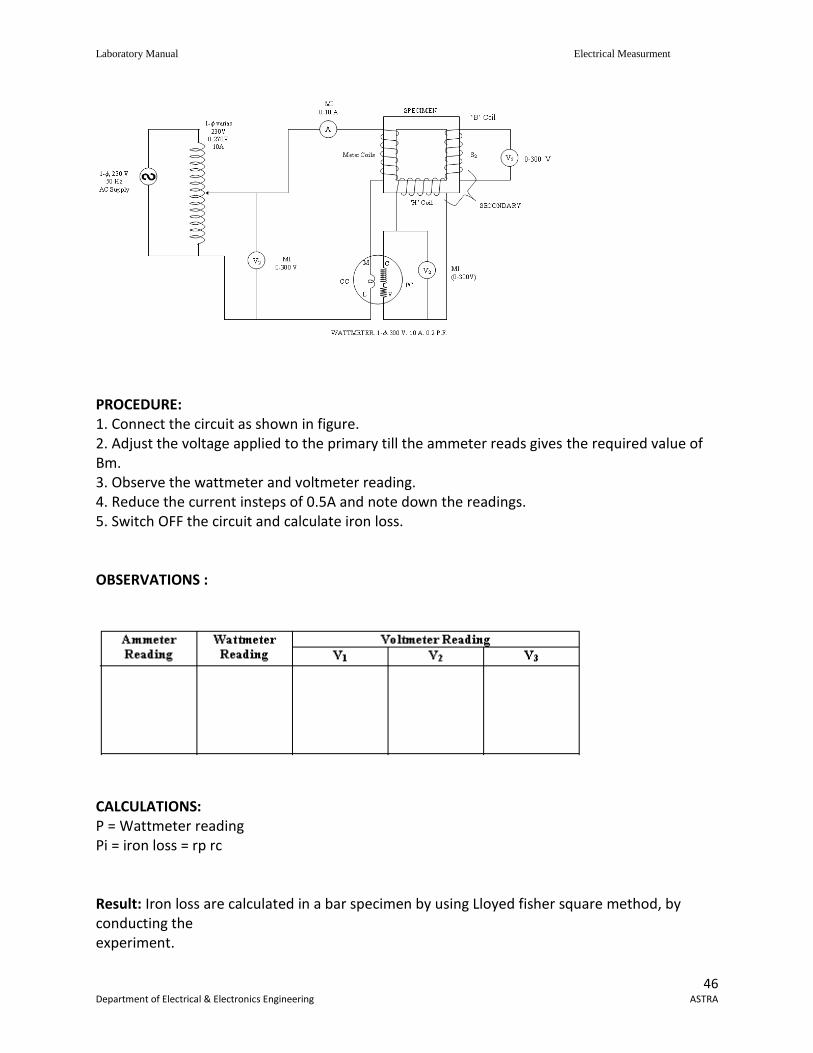
Bm1 = f 2 AK AsfN E(apparent value) As = area of specimen; m2 Bm = Bm1 – μ0Hm Ac = Cross sectional area of coil; m2 Hm = Magnetizing force corresponding to maximum flux density; A/m. (obtained from B.H. curve of specimen) Wattmeter reading = iron loss in the specimen + Copper loss in the secondary Lloyd fisher-square is most commonly used for measurement of iron loss in strip material. The strip material to be tested is assembled as a closed magnetic circuit in the form of a square, called magnetic square. The strips used are usually 0.25m long & 50 to 60mm wide, and ferromagnetic material. Circuit diagram:
Laboratory Manual Electrical Measurment
46 Department of Electrical & Electronics Engineering ASTRA
PROCEDURE: 1. Connect the circuit as shown in figure. 2. Adjust the voltage applied to the primary till the ammeter reads gives the required value of Bm. 3. Observe the wattmeter and voltmeter reading. 4. Reduce the current insteps of 0.5A and note down the readings. 5. Switch OFF the circuit and calculate iron loss. OBSERVATIONS :
CALCULATIONS: P = Wattmeter reading Pi = iron loss = rp rc Result: Iron loss are calculated in a bar specimen by using Lloyed fisher square method, by conducting the experiment.
Laboratory Manual Electrical Measurment
47 Department of Electrical & Electronics Engineering ASTRA
7. Content beyond syllabus:
1: MAXWELL BRIDGE
2: CARY FOSTER BRIDGE
3: OVENS BRIDGE
4: HAYS BRIDGE
5: TESTING OF P.F METER
Laboratory Manual Electrical Measurment
48 Department of Electrical & Electronics Engineering ASTRA
8 Sample Viva Voce Questions.
EXP:1:
1.What is an energy meter? 2. What are the types of energy meter? 3. Which type of energy meters are used in dc circuits? 4. Energy meter is an _____________ (i) integrating instrument (ii) indicating instrument 5. Can the measured percentage error be negative? 6. What do you mean by ‘torque adjustment’? 7. What is operating torque? 8. Define braking torque? 9. When does the disc on the spindle rotate with a constant speed?
EXP:2
1.State the widely used power factor meter? 2. What do you mean by true power? State the formula? 3. Is there any limit in mechanism to develop the controlling torque in dynamometer pf meter? 4. The angular displacement of the coil is proportional to system phase angle. State True/False. 5. What are the two different types of power factor meter? 6. What is the position of the pointer when no current flows in the circuit? 7. Torque acting on the coil P1 is directly proportional to ______________ 8. Torque acting on coil P2 is directly proportional to ______________ 9. The condition for the spindle to be in equilibrium? 10. The angular displacement of the coils is equal to ____________
EXP:3
1. What do you mean by a potentiometer? 2. What are the types of potentiometer? 3. What is the working principle of a potentiometer? 4. What is standardization of potentiometer? 5. What is the purpose of connecting a standard battery in the circuit? 6. Application of dc potentiometer? 7. What do you mean by calibration curve of the ammeter? 8. What do you mean by a volt-ratio box? 9. What are the types of AC potentiometer? 10. What are the practical applications of ac potentiometer?
Laboratory Manual Electrical Measurment
49 Department of Electrical & Electronics Engineering ASTRA
EXP:4
1. Classify resistance? 2. Examples of high resistance? 3. What are the methods employed in measuring low resistances? 4. Which is the most accurate method to measure the low resistances? State the reason? 5. Kelvin double bridge is a modified version of ? 6. What is the main problem in measuring low resistances? 7. How do we measure high resistances? 8. Practical methods to measure earth resistance? 9. What are the quantities that are measured by ac bridges?
EXP:5
1 How types of Silsbee’s methods ? And what are those ? 2 Silsbee’s methods----------- method 3 What is Burden of transformer? 4 Define (C.T&P.T) A. Transformation ratio B. Turns ratio C .Nominal ratio D .RCF 5 Comparison between C.T & P.T
EXP:6
1. What do you mean by high voltage Schering Bridge? 2. State some of the errors that occur in bridge measurements? 3. Anderson Bridge is a modified version of __________ 4. In Anderson Bridge the self inductance is measured in comparison with ___________ 5. What are the resistors need to be adjusted to get the balance 6. At what condition the galvanometer detector will be replaced by the head phone. 7. Schering bridge is used for the measurement of ______________ 8. What is meant by loss angle ? 9. Why we are doing electrostatic shielding for high voltage Schering bridge? 10. What are the elements need to be adjusted to obtain balance in Schering bridge?
Laboratory Manual Electrical Measurment
50 Department of Electrical & Electronics Engineering ASTRA
EXP:7
1. What do you mean by high voltage Schering Bridge? 2. State some of the errors that occur in bridge measurements? 3. Anderson Bridge is a modified version of __________ 4. In Anderson Bridge the self inductance is measured in comparison with ___________ 5. What are the resistors need to be adjusted to get the balance 6. At what condition the galvanometer detector will be replaced by the head phone. 7. Schering bridge is used for the measurement of ______________ 8. What is meant by loss angle ? 9. Why we are doing electrostatic shielding for high voltage Schering bridge? 10. What are the elements need to be adjusted to obtain balance in Schering bridge?
EXP:8
1. How do you measure power ? 2. State the difference between wattmeter and an energy meter? 3. Types of wattmeters? 4. Which types of wattmeter is widely used? 5. How is the controlling torque obtained? 6. What are the errors in dynamometer type wattmeters? State a few. 7. How many wattmeters do we require to measure 3-phase power? 8. What is reactive power ? State the formula. 9. How many wattmeters are required to measure 3-phase reactive power? 10. How do we minimize the errors due to eddy currents in wattmeters?
EXP:9
1. What are the choke coil parameters? 2. What is the function of choke? 3. What are the methods are there to find choke coil parameters? 4. What are the methods are there to find choke coil parameters? 5. Which method is very important for finding the choke coil parameters?
Laboratory Manual Electrical Measurment
51 Department of Electrical & Electronics Engineering ASTRA
EXP:10
1. What is meant by correction factor ? 2. The load current in LPF wattmeter is high / low ? 3. Why are the LPF wattmeter designed to have a smaller controlling torque ? 4. What is the need of introducing compensating coil? 5. State a few errors in dynamometer wattmeter? 6. Applications of LPF wattmeter? 7. Why more operating torque is produced in LPF wattmeter? 8. Why the controlling torque in an LPF wattmeter is less? 9. What are the different methods used for measurement for 3-phase power?
EXP:11
1. What is Burden of transformer? 2. Define (C.T&P.T) A. Transformation ratio B. Turns ratio C .Nominal ratio D .RCF 3 Why C.T secondary should not be opened? 4 Comparison between C.T & P.T
Exp:12=
1. What is LVDT? 2. What is transducer? 3. How many transducers are there? 4. How many windings the transformer in LVDT have in its construction? 5. How the secondaries are connected in the transformer of LVDT?
Exp:13
1. What are the methods of measuring iron losses? 2. What are the two types of squares used to measure iron losses? 3. Which square is preferred to measure iron losses? 4. How the strips are located in Epstein square and Lloyd-Fisher square? 5. What are iron losses? 6. What are the types of iron losses? 7. How the hysteresis loss is minimized? 8. How the eddy current loss is minimized? 9. Define form factor?
Laboratory Manual Electrical Measurment
52 Department of Electrical & Electronics Engineering ASTRA
9. Sample Question paper of the lab external
1 Calibratr And Test the Single Phase Energy Meter
2 Calibrate the Dynamometer Type Power Factor Meter
3 Calibrate the PMMC ammeter and PMMC voltmeter
4 Measure the resistance and Determination of Tolerance
5 TEST the CURRENT TRANSFORMERS
6 Calculate the unknown inductance and capacitance using Anderson bridge. &
shearing bridge
7 Measure the 3 Phase reactive power with single – phase wattmeter
8 Measure the parameters of a choke coil using 3 voltmeter and 3 ammeter methods
9 Calibrate the LPF wattmeter – by Phantom testing
10 Measure the 3 phase power with single watt meter and 2 No’s of C.T.
11 Measure the 3-phase Reactive Power using two wattmeters.
12 MEASURE the IRON LOSS IN A BAR SPECIMEN USING A CRO AND USING A WATTMETER
Laboratory Manual Electrical Measurment
53 Department of Electrical & Electronics Engineering ASTRA
10. Applications of the laboratory :
One of the major goals of this lab is to familiarize the student with the proper equipment and
techniques for making electrical measurements. Some understanding of the lab instruments is
necessary to avoid personal or equipment damage. By understanding the device's purpose and
following a few simple rules, costly mistakes can be avoided.
Laboratory Manual Electrical Measurment
54 Department of Electrical & Electronics Engineering ASTRA
11. Precautions to be taken while conducting the lab
Power must be switched-OFF while making any connections.
Do not come in contact with live supply.
Power should always be in switch-OFF condition, EXCEPT while you are taking readings.
The Circuit diagram should be approved by the faculty before making connections.
Circuit connections should be checked & approved by the faculty before switching on
the power.
Keep your Experimental Set-up neat and tidy.
Check the polarities of meters and supplies while making connections.
Always connect the voltmeter after making all other connections.
Check the Fuse and it’s ratify.
Use right color and gauge of the fuse.
All terminations should be firm and no exposed wire.
Do not use joints for connection wire.
While making 3-phase motor ON, check its current rating from motor name plate details
and adjust its rated current setting on MPCB(Motor Protection Circuit Breaker) by taking
approval of the faculty.
Before switch-ON the AC or DC motor, verify that the Belt load is unloaded.
Before switch-ON the DC Motor-Generator set ON, verify that the DC motor field
resistance should be kept in minimum position. Where as the DC generator / AC generator
field resistance should be kept in Maximum position.
Avoid loose connections. Loose connections leads to heavy sparking & damage for the
equipments as well as danger for the human life.
Before starting the AC motor/Transformer see that their variacs or Dimmerstats always
kept in zero position.
For making perfect DC experiment connections & avoiding confusions follow color coding
connections strictly. Red colour wires should be used for positive connections while black
color wires to be used for Negative connections.
Laboratory Manual Electrical Measurment
55 Department of Electrical & Electronics Engineering ASTRA
After making DPST switch/ICTPN switch-OFF see that the switch in switched-OFF Perfectly
or not. Open the switch door & see the inside switch contacts are in open. If in-contact
inform to faculty for corrective action.
For safety protection always give connections through MCB (Miniature circuit breaker)
while performing the experiments.
SAFETY – II
1. The voltage employed in electrical lab are sufficiently high to endanger human life.
2. Compulsorily wear shoes.
3. Don’t use metal jewelers on hands.
4. Do not wear loose dress
Don’t switch on main power unless the faculty gives the permission4 Do not start the series
motor without load.
5 Keep the armature rheostat in maximum position.
Laboratory Manual Electrical Measurment
56 Department of Electrical & Electronics Engineering ASTRA
12. Code of Conduct
All students must observe the Dress Code while in the laboratory.
Sandals or open-toed shoes are NOT allowed.
Foods, drinks and smoking are NOT allowed.
All bags must be left at the indicated place.
The lab timetable must be strictly followed.
Be PUNCTUAL for your laboratory session.
Experiment must be completed within the given time.
Noise must be kept to a minimum.
Workspace must be kept clean and tidy at all time.
Handle all apparatus with care.
All students are liable for any damage to equipment due to their own negligence.
All equipment, apparatus, tools and components must be RETURNED to their original
place after use.
Students are strictly PROHIBITED from taking out any items from the laboratory.
Students are NOT allowed to work alone in the laboratory without the Lab Supervisor
Report immediately to the Lab Supervisor if any injury occurred.
Report immediately to the Lab Supervisor any damages to equipment.
Before leaving the lab
Place the stools under the lab bench.
Turn off the power to all instruments.
Turn off the main power switch to the lab bench.
Please check the laboratory notice board regularly for updates

Laboratory Manual Electrical Measurment
57 Department of Electrical & Electronics Engineering ASTRA
13. Graphs if any.