Embed Size (px)
Citation preview
I15-027 www.powercommander.com 2002-2006 Harley Davidson Touring Models - PCV - 1
PARTS LIST
1 PowerCommander1 USBCable1 InstallationGuide2 PowerCommanderDecals2 DynojetDecals2 Zip-ties
THE LATEST POWER COMMANDERSOFTWARE AND MAP FILES CAN BE
DOWNLOADED FROM OUR WEB SITE AT:www.powercommander.com
2002-2006 Harley Davidson Touring Models
I ns ta l l a t i on I ns t ruc t i ons
PLEASE READ ALL DIRECTIONS BEFORE STARTING INSTALLATION
THE IGNITION MUST BE TURNED OFF BEFORE INSTALLATION!
2191 Mendenhall Drive North Las Vegas, NV 89081 (800) 992-4993 www.powercommander.com
I15-027 www.powercommander.com 2002-2006 Harley Davidson Touring Models - PCV - 2
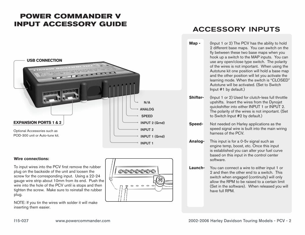
EXPANSION PORTS 1 & 2
OptionalAccessoriessuchasPOD-300unitorAuto-tunekit.
POWER COMMANDER V INPUT ACCESSORY GUIDE
Map - (Input1or2)ThePCVhastheabilitytohold2differentbasemaps.YoucanswitchontheflybetweenthesetwobasemapswhenyouhookupaswitchtotheMAPinputs.Youcanuseanyopen/closetypeswitch.Thepolarityofthewiresisnotimportant.WhenusingtheAutotunekitonepositionwillholdabasemapandtheotherpositionwillletyouactivatethelearningmode.Whentheswitchis“CLOSED”Autotunewillbeactivated.(SettoSwitchInput#1bydefault.)
Shifter- (Input1or2)Usedforclutch-lessfullthrottleupshifts.InsertthewiresfromtheDynojetquickshifterintoeitherINPUT1orINPUT2.Thepolarityofthewiresisnotimportant.(SettoSwitchInput#2bydefault.)
Speed- NotneededonHarleyapplicationsasthespeedsignalwireisbuiltintothemainwiringharnessofthePCV.
Analog- Thisinputisfora0-5vsignalsuchasenginetemp,boost,etc.Oncethisinputisestablishedyoucanalteryourfuelcurvebasedonthisinputinthecontrolcentersoftware.
Launch- Youcanconnectawiretoeitherinput1or2andthentheotherendtoaswitch.Thisswitchwhenengaged(continuity)willonlyallowtheRPMtoberaisedtoacertainlimit(Setinthesoftware).WhenreleasedyouwillhavefullRPM.
ACCESSORY INPUTS
Wire connections:
ToinputwiresintothePCVfirstremovetherubberplugonthebacksideoftheunitandloosenthescrewforthecorrespondinginput.Usinga22-24gaugewirestripabout10mmfromitsend.PushthewireintotheholeofthePCVuntilisstopsandthentightenthescrew.Makesuretoreinstalltherubberplug.
NOTE:Ifyoutinthewireswithsolderitwillmakeinsertingthemeasier.
N/A
ANALOG
SPEED
INPUT 1 (Grnd)
INPUT 1
INPUT 2 (Grnd)
INPUT 2
USB CONNECTION

I15-027 www.powercommander.com 2002-2006 Harley Davidson Touring Models - PCV - 3
1 Removetherighthandside-cover.
2 UnplugthestockwiringharnessfromtheECM(Fig.A).
3 AttachthePCVtothefrontoftheECM,usingthesuppliedzip-tie.Routethezip-tiebehindtheECM.
4 Routeasecondzip-tiebehindtherelayassembly(Fig.B).
5 PlugthestockwiringharnessintotheBLACKconnectorofthePCVwiringharness.
6 PlugtheGREYconnectorfromthePCVwiringharnessontothestockECM.
7 Securetheconnectorsinplaceusingthezip-tie(Fig.C).
8 Reinstallthesidecover.
FIG.A
FIG.B
Unplug
STK
FIG.C
Zip-tie
Zip-tie
PCV
PCV

I15-027 www.powercommander.com 2002-2006 Harley Davidson Touring Models - PCV - 4
Follow these instructions when using the Auto-tune kit - (PN: AT-100B)
Note: Assuming the bike has an exhaust system designed for a 2002-2006 model year Harley Davidson Touring model, it should NOT have 18mm x 1.5 size bungs available in the header pipes for the Auto-tune wideband o2 sensors. In this case, you will need to weld bungs into the exhaust pipes to use Auto-tune. The Auto-tune kits with a part number ending in “B” come with mild steel weld-in bungs provided in the kit.
1 InstallthewidebandO2sensorsprovidedintheAuto-tunekitintothefrontandrearexhaustheadpipes.
2 Removetheseatandtherighthandsidecover.
3 Removetherubberplugforthestockdiagnosticplug.PlugthepowerleadfromtheAutotunemoduleintothediagnosticplug(Fig.D).
4 UsingthesuppliedVelcro,installtheAuto-tunemoduleontopofthePCVmodule.
Make sure the Velcro does not cover the designation of the sensor inputs on the back (#1 or #2). The inputs are coded to the front and rear cylinders.
5 ConnectthelongerharnesstothefrontO2sensor.RoutetheharnessalongthefrontdowntubeandalongthebackboneoftheframetoAutotuneinput#1.WiretheharnesstothemoduleperFigureE.
The harness can be cut to length if desired.
6 Repeatstep5fortherearcylinder.WiretheharnesstoAutotuneinput#2.
The harness can be cut to length if desired.
7 UsetheCANbuscabletoconnecttheAutotunemoduletothePCV.Itdoesnotmatterwhatportsareused.
8 InstalltheCANterminationplugintotheopenportoftheAutotunemodule.This is the BLACK plastic connector in the kit.
9 Securetheharnessesinplaceastonotcontacttheexhaustoranyotherhotormovingparts.
10 Reinstalltheseatandrighthandsidecover.
From the PCV software, go to “Power Commander Tools” -> “Configure” -> “Features, Enables, and Input Selections” to enable the Auto-tune feature.
Gotowww.powercommander.comformapsandsoftwareupdates.
FIG.D
FIG.E
Diag plug
FIG.F