Embed Size (px)
Citation preview
1
Performed By: Khaskin Luba Performed By: Khaskin Luba
Einhorn RazielEinhorn Raziel
Instructor: Rivkin InaInstructor: Rivkin Ina
Spring 2004Spring 2004
Virtex II-Pro Dynamical Virtex II-Pro Dynamical Test ApplicationTest Application
Part A -Part A ---

2
Quick OverviewQuick Overview Examining possible space-compatibility Examining possible space-compatibility
of of civilian devicescivilian devices, in order to integrate , in order to integrate them in satellites.them in satellites.
Statistically modelingStatistically modeling the device’s the device’s robustness to robustness to temporarytemporary damage and it’s damage and it’s ability to recover in a case of an error.ability to recover in a case of an error.
Testing the device under real-time Testing the device under real-time radiation.radiation.

3
The SystemThe System
FPGA Device (Vitex II-Pro)

4
System Block DiagramSystem Block Diagram
DUTDUTVirtex II-Pro Evaluation Board
(platform)
HostHost
JTAG Port USB Port
Xilinx Tools
GUIGUI
Hyper Terminal
Logic Power PC

5
DLP-USB245M ModuleDLP-USB245M Module
Leds , Push-Leds , Push-ButtonsButtons
JTAG JTAG PortPort
LCDLCD
RIO RIO PortsPorts
Virtex II-ProVirtex II-Pro
P130 P130 ModulModulee
DIP DIP SwitcheSwitchess
DUT –Device Under Test – Virtex II-Pro Evaluation BoardDUT –Device Under Test – Virtex II-Pro Evaluation Board
DUTDUT
HostHost

6
The Virtex II-Pro – Closer The Virtex II-Pro – Closer looklook
Specifications:
• Configurable logic block )CLB(
• 18Kb Block-RAMs
• 44 18X18 bit multipliers
• 4 2.5 Gbps Rocket I/O transceivers
• 4 Digital Clock Manager units )DCM(
• Power-PC 4.05 CPU
DUTDUT
HostHost

7
Graphical User InterfaceGraphical User Interface User transparentUser transparent Initializing the testing systemInitializing the testing system Choosing and loading the testing functionChoosing and loading the testing function Receiving data via USB and calculating statistical resultsReceiving data via USB and calculating statistical results
GUI was created in C++ language, using Visual Studio 6GUI was created in C++ language, using Visual Studio 6 Uses supplied Dynamic Library files (Dll files)Uses supplied Dynamic Library files (Dll files)
In order to control the USB moduleIn order to control the USB module
DUTDUT
HostHost

8
Graphical User Interface - Graphical User Interface - AlgorithmAlgorithm
Test in
Process
Gathering test info
Writing appropriate
impl. file
Test typedecision
Opening USB port
Sending start signal
Listening to USB
Collecting datato Excel file
Closing USB port
Delete temporary var .
End Test condition
Opening Excel
START
Test Ended
DUTDUT
HostHost

9
GUI – Main WindowGUI – Main Window
Status Window
Test Type
Tests List
DUTDUT
HostHost

10
GUI – Settings WindowGUI – Settings Window
Programs’ locationUSB connection & drivers check button
DUTDUT
HostHost
11
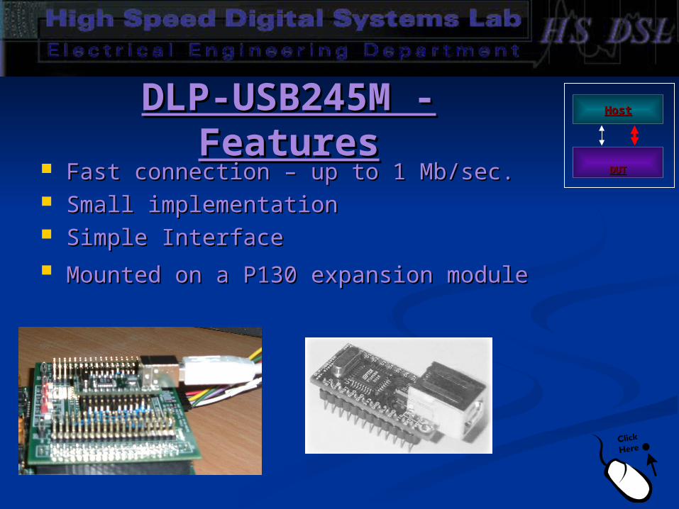
DLP-USB245M - DLP-USB245M - FeaturesFeatures
Fast connection – up to 1 Mb/sec.Fast connection – up to 1 Mb/sec. Small implementation Small implementation Simple InterfaceSimple Interface Mounted on a P130 expansion moduleMounted on a P130 expansion module
DUTDUT
HostHost

12
The Testing ConceptThe Testing Concept

13
The Testing System The Testing System FlowFlow
End Test Comman
d
Creating input and comparison
vectors;Updating
control signals
Listening to Host
Single/Multiple
tests?
Waiting for
outputs
Sending input vectors to
MUT
Multiple tests
Checking outputs;
Sending results
Single test
Loading bit file
TestEnded

14
MUT - Module Under MUT - Module Under TestTest
The examined modules:The examined modules:
I/O BlocksI/O Blocks Fast Multipliers Fast Multipliers Rocket I/ORocket I/O Digital Clock Manager (DCM) Digital Clock Manager (DCM) CLB MemoryCLB Memory CLB Flop-flopsCLB Flop-flops CLB logicCLB logic BRAMsBRAMs Power-PCPower-PC
USBContr.
MCT MUT

15
USB ControllerUSB ControllerUSBContr.
MCT MUT
Controls reading and writing cycles.Controls reading and writing cycles. Determines USB’s control signals during reading Determines USB’s control signals during reading
and writing cycles.and writing cycles. Sets up the relevant data to be sent back to host.Sets up the relevant data to be sent back to host. Designed with minimal usage of logic and Designed with minimal usage of logic and
memory elements.memory elements.

16
USB ControllerUSB ControllerUSBContr.
MCT MUT

17
MCTMCT Identical basic structure for all the testing functions:Identical basic structure for all the testing functions:
- Defines input and comparison vectors in order to test module’s functionality. - Defines input and comparison vectors in order to test module’s functionality.
- Computes the statistical number of errors and instructs their transference - Computes the statistical number of errors and instructs their transference using the USB Controller. using the USB Controller.
Designed with the ambition to maximize the test’s mapping of each examined Designed with the ambition to maximize the test’s mapping of each examined module.module.
Minimal usage of logic and memory elements.Minimal usage of logic and memory elements.
USBContr.
MCT MUT

18
Example – Fast Example – Fast MultipliersMultipliers
USB ControllerUSB Controller
MUTMUT
MCTMCT
USBContr.
MCT MUT

19
Example – Fast Example – Fast MultipliersMultipliers
Several blocks of fast multipliers are chained together to achieve 100% Several blocks of fast multipliers are chained together to achieve 100% mapping.mapping.
The input vectors, set by the MCT, diffuse through the multipliers chain. The input vectors, set by the MCT, diffuse through the multipliers chain. The outputs are being compared with the expected result vectors using The outputs are being compared with the expected result vectors using several feedbacks. several feedbacks.
The calculated errors are being sent via USB, using the USB Controller, in The calculated errors are being sent via USB, using the USB Controller, in steady time intervals.steady time intervals.
USBContr.
MCT MUT

20
Design ToolsDesign Tools HDL Designer – Creating hardware applicationsHDL Designer – Creating hardware applications MODELSIM – VHDL simulation MODELSIM – VHDL simulation Synplify – Synthesis tool Synplify – Synthesis tool Xilinx ISE Project Navigator – Place and RouteXilinx ISE Project Navigator – Place and Route Visual C++ – Designing the GUIVisual C++ – Designing the GUI
21
Part B - Part B - ScheduleSchedule
Implementing tests for the remainder modulesImplementing tests for the remainder modules Learning about PPC & Rocket I/OLearning about PPC & Rocket I/O Learning EDK, Architecture WizardLearning EDK, Architecture Wizard Implementing Power-PC testsImplementing Power-PC tests Implementing Rocket I/O testsImplementing Rocket I/O tests Implementing Special logic tests (e.g. one loop Implementing Special logic tests (e.g. one loop
tests, various user-controllable tests, etc.)tests, various user-controllable tests, etc.)
Redesigning the GUI application respectively.Redesigning the GUI application respectively.
22
Summary and Summary and conclusionsconclusions
First part goals – complete system First part goals – complete system framework, including test implementation, framework, including test implementation, USB connection and application design – USB connection and application design – have been successfully achieved have been successfully achieved
The initially planned communication The initially planned communication channel has been changed from Serial channel has been changed from Serial port (UART) to USB portport (UART) to USB port