Embed Size (px)
Citation preview
1
12
7-8www.adlinktech.com
2
3
4
5
6
7
8
9
10
11
13
14
7-7 www.adlinktech.com
1
12
7-8www.adlinktech.com
2
3
4
5
6
7
8
9
10
11
13
14
7-7 www.adlinktech.com
DSP-based 3/6-axis Analog Motion Control CardsPCI-8253 / PCI-8256
Features■ 32-bit PCI bus, Rev. 2.2, 33 MHz■ On-board 250 MHz DSP ■ 3/6 axes of ±10 volts analog command for controlling servo motors by differential command signal■ Maximum servo update rate is less than 300 µs for 6 axes■ Encoder feedback frequency up to 20 MHz■ Digital filter for encoder input to reduce noise disturbance■ 1/2 channel up to 1 MHz high speed trigger pulse output for PCI-8253/PCI-8256■ A/D inputs (3/6 channels, 14-bit, ±10 V)■ Manual pulse generator inteface■ One dedicated emergency input pin■ High speed position latch function via ORG and Index signals■ On-board 512 kb flash ROM for motion kernel and non-volatile data – PID parameters■ Programmable interrupt source control to host PC■ General purpose I/O: 4 DI/4 DO for PCI-8253 and 8 DI/8 DO for PCI-8256■ Watch dog timer for safety control■ Support for up to 16 cards in one system■ Motion Functions • Jogging mode • Any 2-4 axes linear interpolation • Any 2 axes circular interpolation • Multi-axis synchronized motion • Trapezoidal, S-curve velocity profile • Position override & speed override in anytime • Programmable acceleration/deceleration • Variety of homing modes via signals • Linear and FIFO position comparison method for high speed trigger output • Filter: 2nd order Notch filter and 1 order low pass filter • Blend motion (LookAhead) • E-gear (Electronic gear) • Contouring function by point table description • Gantry mode • Ring counter (32-bit) for rotatory encoder input • Motion trajectory & PID parameters can be changed on-the-fly
Software Support■ Windows® Platform
• Available for Windows Vista (32-bit)/XP/2000 • Recommended programming environments: Visual Basic, Visual C++, Borland C++ Builder, and Delphi
Specifications
PCI-8253PCI-8253
PCI-8256
PCI-8253
PCI-8256
Analog Input / Output Channels ■ Number of Channels 3 for PCI-8253; 6 for PCI-8256 ■ Analog Output ±10 Volt with 16-bit D/A Converter ■ Analog Input ±10 Volt with 14-bit A/D Converter Encoder Input Channels ■ Number of Channels 3 for PCI-8253; 6 for PCI-8256 ■ Max. Encoder Input Frequency 20 MHz under 4 x AB mode ■ Encoder Counter 6-CH, 32-bit ■ Pulse Command Type AB phase and CW/CCW modes Trigger Channels ■ Number of High speed Channels 1 for PCI-8253; 2 for PCI-8256 ■ Number of Low Speed Channels 1 for PCI-8253; 2 for PCI-8256 ■ Maximum Trigger Pulse Frequency 1 MHz for high speed trigger; 25 KHz for low speed trigger ■ Trigger Pulse Width 0.3 µs to 300 ms Motion I/O Interface Signals ■ I/O Pins Differential and 2500 VRMS, optically isolated ■ Incremental Encoder Signals Input Pin EA and EB ■ Encoder Index Signal Input EZ ■ Mechanical Limit Switch Signal Input Pins ±EL and ORG ■ Servomotor Interface I/O Pin INP, ALM, ERC, SVON, RDY ■ Position Compare Output Pin CMP General Purpose I/O ■ Digital Input 4-CH (PCI-8253) / 8-CH (PCI-8256) isolated digital input ■ Input Voltage 0 to 24 V ■ Input Resistance 2.4 KΩ @ 0.5 W ■ Digital Output 4-CH (PCI-8253) / 8-CH (PCI-8256) isolated digital output ■ Output Voltage 5 V (min.); 35 V (max.) ■ Output Type NPN open collector Darlington transistors ■ Current Sink 90 mA Analog Input (A/D) ■ Resolution 14-bit ■ Input Channel 4 single-ended ■ Input Range ±10 V, bipolar ■ Conversion Time 8 µs ■ Sampling Rate 110 K samples/sec (Max.) ■ Accuracy 0.01% of FSR, ±1 LSB General Specifications ■ Connectors 68-pin SCSI-type connector ■ Operating Temperature 0˚C to +55˚C ■ Storage Temperature +20˚C to +80˚C ■ Humidity 5% to 95%, non-condensing
Trigger Channels
Motion I/O Interface Signals
General Purpose I/O
Analog Input (A/D)
General Specifications
DSPinside Closed loop
-
+
AO
Line ARC
T-Curve S-Curve PulserDI/O
H
L
TRO
Contouring Card ID
1Security
STOP
EmergencyInput
AI
1
12
7-8www.adlinktech.com
2
3
4
5
6
7
8
9
10
11
13
14
7-7 www.adlinktech.com
1Software & Utilities
Fanless I/O Platforms
12
7-8www.adlinktech.com
DAQ
2
PXI
3
Modular Instruments
4
GPIB & Bus Expansion
5
PAC
6
Motion
7
Real-time Distributed I/O
8
Remote I/O
9
Communi-cations
10
Vision
11
cPCI & Industrial Computers
13
Accessories
14
7-7 www.adlinktech.com
PCI-8253 / PCI-8256Analog Motion
Pin Assignment
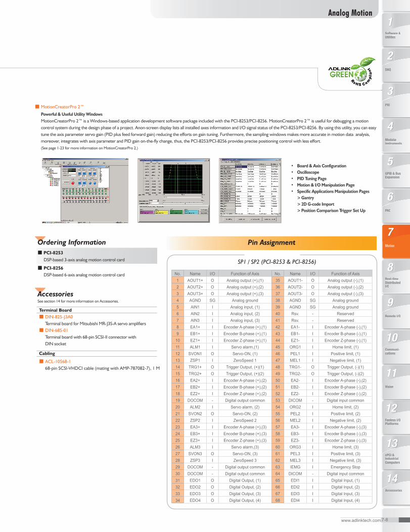
SP1 / SP2 (PCI-8253 & PCI-8256)
No. Name I/O Function of Axis No. Name I/O Function of Axis� AOUT�+ O Analog output (+),(�) 35 AOUT�- O Analog output (-),(�)� AOUT�+ O Analog output (+),(�) 36 AOUT�- O Analog output (-),(�)3 AOUT3+ O Analog output (+),(3) 37 AOUT3- O Analog output (-),(3)4 AGND SG Analog ground 38 AGND SG Analog ground5 AIN� I Analog input, (�) 39 AGND SG Analog ground6 AIN� I Analog input, (�) 40 Rsv. - Reserved7 AIN3 I Analog input, (3) 4� Rsv. - Reserved 8 EA�+ I Encoder A-phase (+),(�) 4� EA�- I Encoder A-phase (-),(�)9 EB�+ I Encoder B-phase (+),(�) 43 EB�- I Encoder B-phase (-),(�)
�0 EZ�+ I Encoder Z-phase (+),(�) 44 EZ�- I Encoder Z-phase (-),(�)�� ALM� I Servo alarm,(�) 45 ORG� I Home limit, (�)�� SVON� O Servo-ON, (�) 46 PEL� I Positive limit, (�)�3 ZSP� I ZeroSpeed � 47 MEL� I Negative limit, (�)�4 TRG�+ O Trigger Output, (+)(�) 48 TRG�- O Trigger Output, (-)(�)�5 TRG�+ O Trigger Output, (+)(�) 49 TRG�- O Trigger Output, (-)(�)�6 EA�+ I Encoder A-phase (+),(�) 50 EA�- I Encoder A-phase (-),(�)�7 EB�+ I Encoder B-phase (+),(�) 5� EB�- I Encoder B-phase (-),(�)�8 EZ�+ I Encoder Z-phase (+),(�) 5� EZ�- I Encoder Z-phase (-),(�)�9 DOCOM - Digital output common 53 DICOM - Digital input common�0 ALM� I Servo alarm, (�) 54 ORG� I Home limit, (�)�� SVON� O Servo-ON, (�) 55 PEL� I Positive limit, (�)�� ZSP� I ZeroSpeed � 56 MEL� I Negative limit, (�)�3 EA3+ I Encoder A-phase (+),(3) 57 EA3- I Encoder A-phase (-),(3)�4 EB3+ I Encoder B-phase (+),(3) 58 EB3- I Encoder B-phase (-),(3)�5 EZ3+ I Encoder Z-phase (+),(3) 59 EZ3- I Encoder Z-phase (-),(3)�6 ALM3 I Servo alarm,(3) 60 ORG3 I Home limit, (3)�7 SVON3 O Servo-ON, (3) 6� PEL3 I Positive limit, (3)�8 ZSP3 I ZeroSpeed 3 6� MEL3 I Negative limit, (3)�9 DOCOM - Digital output common 63 IEMG I Emergency Stop30 DOCOM - Digital output common 64 DICOM - Digital input common3� EDO� O Digital Output, (�) 65 EDI� I Digital Input, (�)3� EDO� O Digital Output, (�) 66 EDI� I Digital Input, (�)33 EDO3 O Digital Output, (3) 67 EDI3 I Digital Input, (3)34 EDO4 O Digital Output, (4) 68 EDI4 I Digital Input, (4)
Ordering Information■ PCI-8253 DSP-based 3-axis analog motion control card
■ PCI-8256 DSP-based 6-axis analog motion control card
Accessories
Terminal Board■ DIN-825-J3A0 Terminal board for Mitsubishi MR-J3S-A servo amplifiers■ DIN-68S-01 Terminal board with 68-pin SCSI-II connector with DIN socket
Cabling
■ ACL-10568-1 68-pin SCSI-VHDCI cable (mating with AMP-787082-7), 1 M
See section 14 for more information on Accessories.
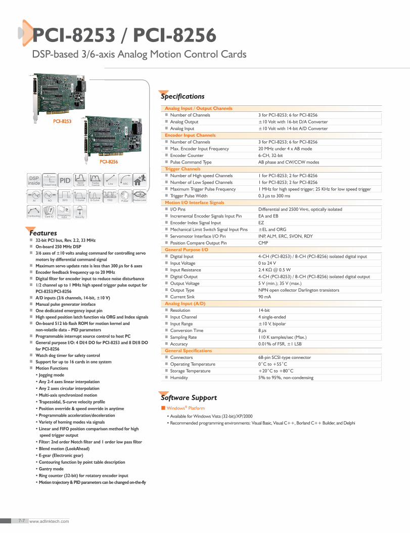
■ MotionCreatorPro 2™
Powerful & Useful Utility Windows MotionCreatorPro 2™ is a Windows-based application development software package included with the PCI-8253/PCI-8256. MotionCreatorPro 2™ is useful for debugging a motion control system during the design phase of a project. Anon-screen display lists all installed axes information and I/O signal status of the PCI-8253/PCI-8256. By using this utility, you can easy tune the axis parameter servo gain (PID plus feed forward gain) reducing the efforts on gain tuning. Furthermore, the sampling windows makes more accurate in motion data analysis, moreover, integrates with axis parameter and PID gain on-the-fly change, thus, the PCI-8253/PCI-8256 provides precise positioning control with less effort. (See page 1-23 for more information on MotionCreatorPro 2.)
• Board & Axis Configuration• Oscilloscope• PID Tuning Page• Motion & I/O Manipulation Page• Specific Applications Manipulation Pages > Gantry > 2D G-code Import > Position Comparison Trigger Set Up