Embed Size (px)
Citation preview

Interior design is a multifaceted and
ever-changing discipline. The practice
of interior design continues to evolve
due to technological as well as societal
changes.
The sentences above were written roughly
ten years ago, in the introduction to the first
edition of this book, and continue to hold
true today. Digital technology continues to
influence and to work as a change agent in
the ongoing evolution of design practice.
Today’s practicing interior designers use
software for drafting, three-dimensional
modeling programs, digital rendering pro-
grams, digital imaging software, as well as a
range of word processing, spreadsheet, and
presentation programs.
In addition to undergoing constant,
rapid technological advancement, the pro-
fession of interior design has grown in
terms of scope of work, specialization, and
the range of design practiced. The growth
of the profession, combined with efforts
toward development of educational stan-
dards, registration, and licensing, have
increased its legitimacy as a serious profes-
sional discipline.
Constant change in society and in one’s
profession can be overwhelming and a bit
frightening, and for that reason it is useful
to consider the elements that remain con-
stant in an evolving profession. In many
ways, the design process itself remains
constant—whether practiced with a stick in
the sand, a technical pen, or a powerful
computer and software. There are many
stories about designers drawing prelimi-
nary sketches on cocktail napkins or the
backs of paper bags, and these stories lead
us to a simple truth.
Professional designers conduct research,
take piles of information, inspiration, and
hard work, and wrap them all together in
what is referred to as the DESIGN PROCESS, to
create meaningful and useful environments.
A constant and key factor in interior design is
the fact that human beings—and other living
creatures—occupy and move within interior
spaces. To create interior environments,
professional designers must engage in a
process that involves research, understand-
ing, idea generation, evaluation, and docu-
mentation. These are significant constants
that exist in a changing world.
For the most part this book covers the
process designers engage in and the relat-
ed presentation techniques used in DESIGN
COMMUNICATION. These processes and
basic concepts are consistent, whether
generated manually or by computer. Some
examples included here were created
ORTHOGRAPHICDRAWINGS
1
1
04_741565 ch01.qxd 11/13/07 2:40 PM Page 1
COPYRIG
HTED M
ATERIAL

2 I N T E R I O R D E S I G N V I S U A L P R E S E N TAT I O N
manually, whereas others were computer
generated. Regardless of how drawings and
graphics are generated, they are part of a
process of discovery, exploration, and cre-
ation.
This chapter covers what is often
referred to as drafting, as well as other
forms of two-dimensional graphics; this
specific type of drawing is required for all
projects that will be constructed. The term
DRAFTING refers to measured drawings done
with specialized tools and equipment. The
truth is that not all drawings used in the
process of interior design are drawn with
the aid of drafting tools or computers.
Often those drawings created in the pre-
liminary stages of the design process are
rough sketches and involve little use of
drafting tools or equipment. As designs are
refined, there is clearly a need for highly
accurate, measured, and detailed drawings,
and these are drafted with tools.
This chapter presents the materials,
equipment, and tools used for manually
drafted and freehand design drawings, as
well as an overview of the most common
drawings used in interior design practice.
The information presented in this chapter
is meant as an overview, not a definitive
drawing or drafting reference. Subsequent
chapters cover the other forms of drawings
and design graphics used in sketching, and
other forms of idea generation.
MATERIALS, TOOLS, ANDEQUIPMENT FOR MANUALDRAFTINGThe graphics and drawings used in interior
design practice vary, ranging from concep-
tual sketches and rough layouts to meas-
ured technical drawings. The materials,
tools, and equipment used to create the
variety of drawings and graphics are
numerous and ever proliferating. The
media and tools selected must be appropri-
ate to the task at hand. This means that
their proper selection requires careful
consideration of the drawing type and use,
as well as an understanding of the available
products. Currently most schools and
FIGURE 1-111. Compass2. Architectural scales3. Drafting film4. Template5. T square6. Lettering triangle7. Triangle8. Appliqué film9. Vellum
10. Tracing paper (roll)11. Cork-backed ruler12. Flexible curve13. Drafting tape14. Drafting dots15. French curve16. French curve17. Adjustable triangle18. Electric eraser19. Eraser shield20. Erasers21. Dry-cleaning pad22. Disposable ink pens23. Technical pen24. Lead holder25. Lead pointer26. Mechanical pencil27. Wooden graphite pencils28. Layout pencils29. Drafting brush
29
28
2726
2524 23
22
19
21
20
1815
14
12
13
17
4
21 3
67
9 10
8
11
5
16
1-1
04_741565 ch01.qxd 11/13/07 2:40 PM Page 2

design firms create the majority of design
drawings digitally, using COMPUTER-AIDED
DESIGN (CAD) programs. However, some
students begin the study of drafting by cre-
ating drawings manually; for that reason a
description of manual drawing tools and
equipment follows. Figure 1-1 illustrates
commonly used manual drafting and draw-
ing materials and equipment, which are
discussed as follows.
Drawing SurfacesThe type of drawing surface selected
directly affects the quality of the drawn
image. Some surfaces accept pencil and ink
readily and allow for clear, consistent
imagery. Transparent papers allow for
diazo reproduction (blueprinting) and can
be used as an overlay to continue a drawing
by transferring details from one sheet to
another. Drawings produced on nontrans-
parent surfaces are reproduced by photo-
copying, digital reproduction (scanning),
or photographic processes.
TRACING PAPER is the most common paper
surface for sketching in-process design
drawings and graphics. Known in various
parts of the country as trace, flimsy, and
bumwad, this paper is highly transparent
and relatively inexpensive. Tracing paper
is available in cut sheets and in rolls in a
variety of sizes. Rolls of tracing paper work
well for interior design drawing because of
the varying sizes of drawings required.
Tracing paper is available in white, buff,
and canary (yellow). Most designers have a
personal color preference based on previ-
ous experience. Some designers use trac-
ing paper to create actual presentation
sketches (used to communicate with a
client or end-user) while others use them
only for personal exploration.
Because tracing paper is relatively inex-
pensive, it can be used to develop prelimi-
nary sketches and for in-process drawings.
This allows for exploration through the
creation of many sketches and the genera-
tion of many ideas. Tracing paper also
works very well overlaid on drawings for
transfer and refinement of images. Often
many layers of tracing paper are overlaid as
a design is refined or as a complicated per-
spective drawing is constructed. Images on
tracing paper can be reproduced easily by
being photocopied or being scanned for
inclusion in design presentations.
While this is done less commonly in
current practice, final design drawings cre-
ated manually and intended for diazo
reproduction are drawn on DRAFTING VELLUM,
a transparent paper available in a variety of
finishes and weights (thicknesses) and
most often white. Drafting vellum should
have a high rag or cotton content, giving it a
rich finish, strength, and good stability. It
is excellent for line work generated with
graphite pencils. Good-quality diazo prints
can be run from drafting vellum originals.
Vellum is also photocopied, scanned, and
photographed with excellent results.
In addition to vellum, PLASTIC DRAFTING
FILMS are used for final drawings and for
some design presentations. Plastic (and
polyester) drafting films are expensive,
tear resistant, and generally do not react to
fluctuations in temperature or humidity (as
do many paper surfaces). They accept ink
beautifully and allow for easy ink erasure.
These films require the use of special pen-
cils. Drafting film originals produce excel-
lent diazo prints and photocopies. For
years prior to the use of CAD, plastic film
and ink drawings were considered the
finest for reproduction.
A range of ART PAPERS is available; the
papers are made with a variety of materials
and come in many colors, sizes, and finishes.
Some of these papers can be used as a draw-
ing surface or as a background or visual ele-
ment included within a presentation; a range
of paper types is discussed in Chapter 5,
beginning on page 145.
O R T H O G R A P H I C D R AW I N G S 3
04_741565 ch01.qxd 11/13/07 2:40 PM Page 3

4 I N T E R I O R D E S I G N V I S U A L P R E S E N TAT I O N
ADHESIVE REPRODUCTION FILM, also
called appliqué film and often referred to
generically as sticky back, is used on vellum
or bond drawings. Typed or printed images
can be drawn or photocopied onto adhesive
reproduction film. The film is then care-
fully measured and cut and applied to the
vellum or bond paper.
Manually generated design drawings
can be reproduced on large-format photo-
copying machines. However, CAD-gener-
ated drawings—printed or plotted on bond
paper—are the most commonly used in
current practice. It is also worth noting that
many designers and design firms scan
hand drawings and combine them with
additional graphics using imaging software
such as Photoshop or page layout software
such as InDesign® to create digital presen-
tations such as those in discussed in
Chapter 5, page 157 (Digital Rendering).
Line- and Mark-MakingImplementsLines and marks record spatial informa-
tion in interior design drawings and graph-
ics. Control of line thickness and the type
of stroke used are important and convey
specific information. Thus, the implement
used to create lines and marks is a key fac-
tor in manually created design drawings.
GRAPHITE is mixed with clay and other
elements to produce what are commonly
called lead pencils. Graphite pencils, used
in design drawing, are available in a range
of hardnesses based on the mixture of clay
to graphite. Graphite pencils and replace-
able “leads” are coded with a standard rat-
ing system: H stands for hard, B stands for
black (the softer leads). The number found
next to the H or B refers to the level of
hardness. For example, a 6B is softer than a
2B; an 8H is very hard. F-rated leads are at
the center of the range, and HB leads are
slightly harder than Bs. The softer leads are
used in sketching and rendering, whereas
H, 2H, and sometimes F leads are most
commonly used in drafting.
The graphite described above is used in
a variety of mark-making implements.
WOODEN DRAWING PENCILS involve a graph-
ite mixture encased in wood and are sharp-
ened like standard wooden writing pencils.
MECHANICAL PENCILS are hollow instru-
ments that hold very fine graphite leads.
These are sold in a variety of lead widths to
create a range of line weights. LEAD HOLDERS
are hollow implements that accept thicker
leads than mechanical pencils. Although
lead holders do not allow for any variety in
lead widths, they do accept a range of lead
types in terms of softness. Lead holders
require the use of a specialized sharpener,
known as a LEAD POINTER.
Specialized colored drafting pencils and
leads can be used to develop drawings prior
to hard-lining them. NONPHOTO-BLUE col-
ored pencils do not reproduce when pho-
tographed; however, they sometimes
reproduce when photocopied. NONPRINT
colored pencils do not reproduce in diazo
prints. When appropriate, both types of
pencil can be used to lay out drawings prior
to completion.
One of the significant advantages of
using graphite pencils is the ease of eras-
ing. Harder leads are often the most diffi-
cult to erase, whereas soft pencil marks are
easily lifted with gray kneaded erasers or
pink erasers. Plastic and film erasers can
be used to remove marks made with harder
leads. A metal ERASER SHIELD is used to pro-
tect the drawing surface from unwanted
erasing. DRY CLEANING PADS, containing art
gum powder that sifts onto drawing sur-
faces, are available to keep drawings clean.
TECHNICAL PENS have tubular points and
refillable ink reservoirs. They are available
in a range of point sizes that allow for
absolute control of line weight. Because
they employ black ink and metal points,
technical pens create the finest line work of
04_741565 ch01.qxd 11/13/07 2:40 PM Page 4

any drawing implement. They must be used
with the appropriate ink, as specified by the
manufacturer.
DISPOSABLE TECHNICAL PENS combine a
tubular support with a felt tip and are avail-
able in a range of point sizes. These pens
require no maintenance or cleaning, mak-
ing them easy to use. Although disposable
pens have been known to skip, causing
inconsistent line work, they have improved
a great deal recently and are becoming very
popular.
FELT-TIP PENS are available in a range of
styles and point sizes; they are often used in
sketching, exploration, and rendering.
Felt-tip pens are not generally used for
refined drafted drawings or working draw-
ings.
Erasing ink marks is rather difficult and
requires special erasers. Hard plastic
erasers can remove ink. However, an ELEC-TRIC ERASER with the appropriate eraser
insert is most useful in removing ink.
Electric erasers are very effective but must
always be used with an eraser shield. Ink
marks on film are erased more easily than
those on vellum. Sharp razor blades are
sometimes used to scrape ink away from
drawing surfaces.
A quality DRAWING BOARD is required for
the creation of successful drawings.
Serious students must purchase a top-
quality drawing board if possible. The
board should accommodate a minimum
paper size of 24 inches by 36 inches.
Drawing boards should be covered with a
specialized vinyl drawing surface, sold at
drafting and art supply stores. The vinyl
surface helps to improve line consistency.
T SQUARES are used in conjunction with
the edge of the drawing board to provide an
accurate horizontal line or right angle for
drawings. PARALLEL RULERS can be attached
to drawing boards using a system of screws,
cables, and pulleys. This creates the sliding
straightedge that is the standard in profes-
sional practice. Triangles are used with a T
square to create vertical and angled lines.
Adjustable and 45/45-degree and 30/60-
degree triangles are readily available.
Triangles should be fairly clear, easy to see
through, and as substantial as possible. An
inking triangle with raised edges is required
when using ink. It is also useful to have a
tiny triangle on hand as an aid in lettering.
Triangles should never be used as a cutting
edge; this will ruin them. A cork-backed
metal ruler is the best edge for cutting.
DRAFTING TAPE or PRECUT DRAFTING DOTS
are used to attach drawings to drawing
boards. Unlike standard masking and
household tape, drafting tape and dots are
easy to remove from both the paper and the
drawing board. A DRAFTING BRUSH is used to
remove eraser debris from the drawing
surface.
Measured interior design drawings
require the use of a proportional scale. This
allows for large areas to be reduced in size
to fit on relatively small drawings. An
ARCHITECTURAL SCALE is the standard scale
ruler used in interior design drawing. In
the United States, standard architectural
scales employ imperial units, that is feet
and inches. Standard architectural scales
are marked incrementally with numbers
running from left to right, with a number or
fraction to the right or left of the incremen-
tal lines that indicate scale. For example, in1⁄4-inch scale the ruler is marked so that
each 1⁄4-inch measures 1 foot in scale.
Architectural scales have inches marked
below the zero marking; these are used to
measure elements that are not exact to the
foot. In transferring measurements, great
care should be taken to record accurate
dimensions. Scale rulers should never be
used to draw against, as this would result in
poorly drawn lines and damaged rulers.
More information on the actual scales used
for specific types of drawings can be found
later in this chapter.
O R T H O G R A P H I C D R AW I N G S 5
04_741565 ch01.qxd 11/13/07 2:40 PM Page 5

6 I N T E R I O R D E S I G N V I S U A L P R E S E N TAT I O N
An ENGINEER’S or ENGINEERING SCALE is
used for measuring larger scale items, typ-
ically related to building sites, roads, topo-
graphical features and other items such as
water and sewer lines. In the United States
these scales are based on imperial units—
that is feet. These scales are marked incre-
mentally with numbers running from left
to right only, with a number given at the left
of the incremental lines that indicates
scale. These scales measure in parts to the
inch, such as 1 inch equals 10 feet, or one
inch equals 20 feet and so on up to 60 feet—
on standard scales. In using an engineer
scale, each value given requires that you
multiply the value by 10. For example, using
the portion of the scale where 1 inch equals
10 feet; where the 1 is written actually meas-
ures 10 feet, and where the 2 is written
equals 20 feet. Individual increments
marked by small lines along the ruler
(without numbers written next to them)
represent individual feet—for example, two
small line marks to the right of 2 represents
22 feet.
METRIC SCALES are standard throughout
most of the world (with the exception of the
United States) and represent meters (m)
and centimeters (cm) or millimeters
(mm). Much like the aforementioned engi-
neer’s scale, these scales are based on
ratios, such as 1:50, where 1 millimeter
would scale to represent 50 millimeters.
More information on the actual scales used
for specific types of drawings can be found
later in this chapter. It is worth noting that
the simplified modern version of the met-
ric system is properly called the Inter-
national System of Units, symbolized by SI,
according to the U.S. Metric Association;
this system includes other units of meas-
urement as well.
TEMPLATES are most commonly con-
structed of plastic and are used much like
stencils to draw various shapes, including
circles, ellipses, furnishings, and fixtures.
The more expensive templates—constructed
of heavy, durable plastic—are worth the
extra money. Furniture and fixture tem-
plates work well to quickly lay out and plan
spaces. However, in presentation drawings
furniture and fixtures drawn from tem-
plates can appear artificial and monoto-
nous.
FRENCH CURVES are drawn against as an
aid in producing curved lines. FLEXIBLE
CURVES, also known as snakes, are also used
as an aid in drawing curved lines. These
have flexible spines that can be bent to
accommodate the desired curve. These also
work well for transferring curves from one
drawing surface to another. A COMPASS is
used for drawing accurate circles and arcs
and is useful in situations where a template
does not contain a circle of the required
size. It is worthwhile to purchase a good
compass that adjusts easily and accepts
drawing leads and ink heads.
UNDERSTANDINGORTHOGRAPHIC PROJECTIONDRAWINGSThe practice of interior design requires the
creation and use of various types of draw-
ings. These can be divided into three broad
categories based on purpose. The first type
of drawing allows the designer to explore
ideas (known as ideation) and work concep-
tually, often in the form of sketches. The
second type allows the designer to commu-
nicate to others, including members of the
design team, the client, end users, consult-
ants, and other professionals (presentation
drawings). A third type of drawing conveys
the technical information required for con-
struction (construction documents or
working drawings). This book focuses on
the first two types of drawing: those used for
exploration and presentation or for graphic
communication of ideas.
Unlike ideation sketches, presentation
drawings and construction documents
FIGURE 1-2When an object is enclosed in a glass box, each plane of the box can serve as a pic-ture plane. The view throughthe top plane (picture plane)creates a plan view, in this case a roof plan.
FIGURE 1-3The view through the pictureplane enclosing the side of thebox is called an elevation.
FIGURE 1-4A section is a view of an objectwith the picture plane slicingneatly through it.
FIGURE 1-5A floor plan is a view of thebuilding from above with a horizontal plane sliced throughit and removed to expose thethickness of the walls.Figures 1-2 through 1-5 drawn by
Ciarah Coenen
04_741565 ch01.qxd 11/13/07 2:40 PM Page 6

must use certain standard drawing con-
ventions to clearly communicate and
delineate the proposed design; these gen-
erally involve drafting in scale. Unlike
fine art drawing, design drawing requires
adherence to conventions, proportional
scale, and accuracy of line. Design draw-
ings are highly standardized so that they
carry universal meaning. Or, as one early
reviewer of this book put it, “Design
drawing is much like a language; the draw-
ings must convey the designer’s meaning
clearly.”
While this publication does not cover
them in any detail, highly technical con-
struction drawings are always drafted in
scale, either manually or using CAD, and
they employ many of the concepts covered
in this chapter. They are, however, quite
distinct and follow very specific conven-
tions and because of this should be studied
in detail by interior design students—
toward that end, the References section of
this chapter lists two books that describe
and illustrate construction drawings clearly
for students. Various examples of technical
O R T H O G R A P H I C D R AW I N G S 7
1-2 1-3
1-4 1-5
04_741565 ch01.qxd 11/13/07 2:40 PM Page 7

8 I N T E R I O R D E S I G N V I S U A L P R E S E N TAT I O N
construction drawings can be found at the
end of this chapter in Figures 1-17a through
1-17d and Figures 1-18a through 18-c.
The design drawings most commonly
used in scaled delineation of interior envi-
ronments are floor plans, interior elevations,
sections, and reflected ceiling plans. These
drawings, called ORTHOGRAPHIC PROJEC-TIONS, are created by projecting informa-
tion about an object onto an imaginary
plane known as the PICTURE PLANE. This
direct projection of an object’s dimensions
allows orthographic projections to retain
shape and proportion, making these draw-
ings accurate and precise.
Orthographic projection creates frag-
mentary views of an object, resulting in the
need for multiple drawings. This means
that because of their fragmentary nature
orthographic projections become parts of
a system and are mutually dependent on
one another. By their nature, orthographic
projections appear flat and lack the three-
dimensional quality of perspective draw-
ings. One way to visualize orthographic
projection is to imagine an object enclosed
in a transparent box. Each transparent
plane of the enclosing box serves as the
picture plane for that face of the object
The view through the top plane of the
enclosing box is called a PLAN. In a plan
view only those elements seen when look-
ing directly down at the object are drawn.
Figure 1-2 depicts a roof plan.
The views through the picture planes
that form the sides of the enclosing box are
called ELEVATIONS. Elevations depict only
what is visible when viewed directly
through the picture plane. Figure 1-3 is an
exterior elevation.
FIGURE 1-6aCommon graphic notationsused in orthographic projectiondrawings.
1-6a
04_741565 ch01.qxd 11/13/07 2:40 PM Page 8

A SECTION portrays a view of the object
or building with a vertical plane sliced
through it and removed. One way of under-
standing section views is to imagine that a
very sharp plane has been inserted into the
object or building, cutting neatly into it and
revealing the structure and complexity of
the object’s form (see Figure 1-4).
A FLOOR PLAN, also known as a horizon-
tal section, portrays a view of the building
with a horizontal plane sliced through it
and removed, exposing the thickness of the
walls and the elements below the cut line
such as floor finishes and furniture (see
Figure 1-5).
Orthographic projection drawings are
clearly an abstraction of reality and use
specific conventions to delineate space and
materials. Unlike some other forms of
drawing, orthographic projection drawings
require adherence to conventions, propor-
tional scale, and accuracy of line; these
design drawings are highly standardized so
that they carry universal meaning. There-
fore, items such as walls, doors, windows,
property boundaries, references to other
FIGURE 1-6bGraphic symbols used for refer-ences and notes. Items shownwith a 1 near them are referencesymbols that include a numberon top of another number. Thenumber on top refers to thedrawing number and the lowernumber refers to the sheet thedrawing may be found on.
O R T H O G R A P H I C D R AW I N G S 9
1-6b
04_741565 ch01.qxd 11/13/07 2:40 PM Page 9

10 I N T E R I O R D E S I G N V I S U A L P R E S E N TAT I O N
drawings and other items are represented
by very specific graphic symbols or combi-
nations of lines. Figures 1-6a, 1-6b, and 1-
6c illustrate some graphic notations used
in these types of drawings such as wall
lines, door and window symbols, as well as
reference and notation symbols.
ORTHOGRAPHIC PROJECTIONDRAWINGS FOR INTERIORENVIRONMENTSThe special orthographic projection
drawings used in delineation of interior
environments are based on the concepts
mentioned to this point. These drawings
impart information particular to interior
construction.
Floor PlansAs stated, floor plans can also be called
HORIZONTAL BUILDING SECTIONS, this is
because they are drawn as though a hori-
zontal cut has been made in the building
(typically between 3 feet 6 inches and 5 feet
6 inches above the floor) as shown in
Figure 1-7. Cutting into the building at this
location exposes the thickness of walls and
other structural elements, and shows win-
dows, doors, and can show floor finishes
and furnishings—all of which are located
below the location of the cut.
In the United States, floor plans are
most often drawn at a scale of 1⁄8" = 1'0" or 1⁄4" = 1'0", although this varies according
to project conditions. Larger-scale floor
FIGURE 1-6cGraphic symbols used for light-ing and electrical information. Figures 1-6a through 1-6c drawn by
Melissa Brewer
DUPLEX RECEPTACLE WITHGROUND FAULT INTERRUPTER
WIRING AND OUTLET SYMBOLS ELECTRICAL DEVICES, SWITCHES, AND PANELBOARD SYMBOLS
DUPLEX RECEPTACLE(INDICATE NONSTANDARDMOUNTING HEIGHT)
SPECIAL PURPOSE RECEPTACLE(INDICATE NONSTANDARDMOUNTING HEIGHT)
DATA COMMUNICATIONS OUTLET(INDICATE NONSTANDARDMOUNTING HEIGHT)
CEILING-MOUNTEDLIGHT FIXTURE(INDICATE TYPE)
WALL WASHER(INDICATE TYPE; SHADINGINDICATES LIGHTED FACE)
SPOTLIGHT(INDICATE TYPE; ARROWINDICATES DIRECTION OF FOCUS)
FLUORESCENT FIXTURE(INDICATE TYPE; DRAW TO SCALE)
FLUORESCENTSTRIP LIGHT(INDICATE TYPE; DRAW TO SCALE)
LIGHT TRACK(INDICATE TYPE; SHOW NUMBEROF FIXTURES REQUIRED)
TELEPHONE OUTLET(INDICATE NONSTANDARDMOUNTING HEIGHT)
DUPLEX FLOOR RECEPTACLE
RANGE OUTLET
BELL
PHOTOELECTRIC CELL
ELECTRIC THERMOSTAT
(RECESSED)PANELBOARD ANDCABINET
SINGLE POLE SWITCH
THREE-WAY SWITCH
FOUR-WAY SWITCH
DIMMER SWITCH
SPLIT-WIRED DUPLEXRECEPTACLE OUTLET
SWITCH(*D–DOOR; K–KEY OPERATED;LV–LOW VOLTAGE;M–MOMENTARY CONTACT;P–PILOT LIGHT)
CLOCK RECEPTACLE(INDICATE MOUNTING HEIGHT)
ELECTRICAL AND LIGHTING SYMBOLS
HEIGHT
HEIGHT
HEIGHT
HEIGHT
HEIGHT
GFI
C
S
S*
S3
S4
SDIM
PE
R
1-6c
04_741565 ch01.qxd 11/13/07 2:40 PM Page 10
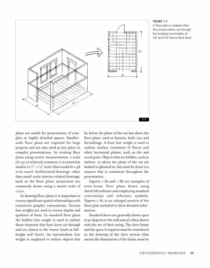
plans are useful for presentation of com-
plex or highly detailed spaces. Smaller-
scale floor plans are required for large
projects and are also used as key plans in
complex presentations. In creating floor
plans using metric measurements, a scale
of 1:50 is relatively common; it is somewhat
similar to 1⁄4" = 1'0" scale (that would be 1:48
to be exact). Architectural drawings—other
than small-scale interior related drawings,
such as the floor plans mentioned—are
commonly drawn using a metric scale of
1:100.
In drawing floor plans it is important to
convey significant spatial relationships with
consistent graphic conventions. Various
line weights are used to convey depths and
qualities of form. In standard floor plans
the boldest line weight is used to outline
those elements that have been cut through
and are closest to the viewer (such as full-
height wall lines). An intermediate line
weight is employed to outline objects that
lie below the plane of the cut but above the
floor plane, such as fixtures, built-ins, and
furnishings. A finer line weight is used to
outline surface treatment of floors and
other horizontal planes, such as tile and
wood grain. Objects that are hidden, such as
shelves, or above the plane of the cut are
dashed or ghosted in; this must be done in a
manner that is consistent throughout the
presentation.
Figures 1-8a and 1-8b are examples of
town-house floor plans drawn using
AutoCAD software and employing standard
conventions and reference symbols.
Figures 1-8c is an enlarged portion of the
floor plan included to show detailed infor-
mation.
Standard doors are generally drawn open
at 90 degrees to the wall and are often shown
with the arc of their swing. The door frame
and the space it requires must be considered
in the drawing of the door system (this
means the dimensions of the frame must be
O R T H O G R A P H I C D R AW I N G S 11
FIGURE 1-7A floor plan is created whenthe picture plane cuts throughthe building horizontally, at 3'6" and 5'6" above floor level.
1-7
04_741565 ch01.qxd 11/13/07 2:40 PM Page 11

12 I N T E R I O R D E S I G N V I S U A L P R E S E N TAT I O N
FIGURE 1-8aTown-house lower-level floor plan employ-ing standard drafting conventions.
1. Boldest lines indicate the location ofcut, meaning full-height walls are bold.Lower walls may be shown with lighter lineweights (1a).
2. Fixtures, cabinetry, and finish materialsare drawn with progressively lighter lines asthey recede from the cut location.
3. Elements that are above or below thecut line—such as cabinets (3a) and soffits—or hidden such as dishwashers, are indicat-ed with dashed lines.
4. Standard doors are drawn open at 90degrees with the arc of swing shown; the
full swing can be shown ensure that nothingimpedes the full swing of the door.
5. Specialized doors, such as smallercloset doors (shown), bi-fold doors, slidingdoors, and pocket doors, are drawn in away that indicates size and construction.
6. Window glass and sill lines are shown,often with a lighter-weight line than walls.
7. Stairs are drawn as broken off past theline of the cut; a special breakline is used.
8. A title, north arrow, and scale notationare required on all plans. Because this draw-ing was reduced, a standard written scalewas omitted; instead, a graphic scale deviceis included.
9. This is a section reference symbol. Thearrow indicates the direction of the view ofthe section. 10. This is an elevation reference symbol.The arrow indicates the direction of the ele-vation view. The number indicates the par-ticular drawing that is referenced.11. Flooring materials may be shown asrequired (using a light line weight). 12. This is a centerline, indicating the cen-terline of the shared wall in the town house.
10
3
3
6
9
4
1
8
1a
3a 3
2
12
5
5
11
7
1-8a
considered). Doors other than standard such
as smaller swinging closet doors, bi-fold,
sliding and pocket types are drawn in a man-
ner that is consistent with their construction
as shown in Figure 1-6a. Windowsills are
typically outlined, often with a lighter line
weight at the sill only. Window frames and
sheets of glass are shown in various details as
scale allows. Stairs are generally shown as
broken off past the height of the plane of the
cut; this is signified with a special cut or
breakline as shown in Figure 1-8a. An arrow
should be included to indicate the direction
of the stairs from the level of the floor plan,
with the word up or down (dn) adjacent to the
directional arrow.
A title, a north arrow, and some type of
scale notation should be included on all
04_741565 ch01.qxd 11/13/07 2:40 PM Page 12

floor plans. Scale notation can be stated
numerically, for example: 1⁄4" = 1'0".
Current practice often requires the use of a
graphic scaling device, which allows for
reduction, enlargement, and electronic
transmission of the drawings.
Symbols relating the floor plan to addi-
tional orthographic views or details are
often drawn on the floor plan and serve as
cross-references.
Successful floor plan presentation
drawings require a thorough understand-
ing of drafting conventions. Presentation
floor plans may be drawn fastidiously with
tools or drawn freehand. Regardless of the
style of drawing, presentation floor plans
must be accurate and drawn to the appro-
priate scale so that they communicate the
design and can be used by the designer as
the project moves forward. Presentation
floor plans are enhanced by the use of tone,
value, color, and other graphic devices. The
graphic enhancement of floor plans is dis-
cussed in greater detail in Chapter 5, page
151. Additional examples of plans for com-
mercial projects may be found at the end of
this chapter beginning with Figures 1-17a
and 1-18a.
Interior ElevationsJust as exterior elevations are created to
reveal exterior elements and features, inte-
rior elevations reveal the interior features
of a building. One way to understand the
creation of interior elevations is to imagine
ourselves inside the room we are drawing.
Imagine standing inside a room facing one
wall directly, with a large sheet of glass (the
picture plane) inserted between the viewer
and the wall. The interior elevation can
then be created by outlining (projecting
onto the picture plane) the significant fea-
tures of the wall. Each wall of the room can
be drawn in elevation by means of project-
ing what is visible as the viewer faces that
wall directly as illustrated in Figure 1-9.
Interior elevations are used extensively in
professional practice. Successful elevations
FIGURE 1-8b1. Boldest lines indicate the
location of cut, meaning full-height walls are bold. Lowerwalls may be shown with lighterline weights (1a).
2. Fixtures, cabinetry, and fin-ish materials are drawn withprogressively lighter lines as theyrecede from the cut location.
3. Elements that are above orbelow the cut line—such ascabinets (3a) and soffits—orhidden such as dishwashers,are indicated with dashed lines.
4. Standard doors are drawnopen at 90 degrees with the arcof swing shown; the full swingcan be shown ensure that noth-ing impedes the full swing ofthe door.
5. Specialized doors, such assmaller closet doors (shown),bi-fold doors, sliding doors,and pocket doors, are drawn ina way that indicates size andconstruction.
6. Window glass and sill linesare shown, often with a lighter-weight line than walls.
7. Stairs are drawn as brokenoff past the line of the cut; stairsfrom lower floors are shown.
8. A title, north arrow, andscale notation are required onall plans. Because this drawingwas reduced, a standard written scale was omitted;instead, a graphic scale deviceis included.
9. This is a section referencesymbol. The arrow indicates thedirection of the view of the sec-tion. 10. These are elevation refer-ence symbols. The arrow indi-cates the direction of the viewof the elevation. 11. This is a centerline, indicat-ing the centerline of the sharedwall in the town house.
O R T H O G R A P H I C D R AW I N G S 13
1
5
7
2
8
6
3
9
10
4
1-8b
04_741565 ch01.qxd 11/13/07 2:40 PM Page 13

14 I N T E R I O R D E S I G N V I S U A L P R E S E N TAT I O N
must clearly depict all interior architectural
elements in a consistent scale. Interior ele-
vations are typically drawn in a scale ranging
from 1⁄4" = 1'0" to 1" = 1'0". Elevations drawn
to depict accessories, equipment, cabinetry,
fixtures, and design details are often drawn at3⁄8" = 1'0" or 1⁄2" = 1'0". Millwork and other
highly complicated elevations are often
drawn at 1⁄2" = 1'0" or larger.
All elevations require the use of differing
line weights to clearly communicate spatial
relationships. Typically, any portion of walls
cut through and those closest to the viewer
are drawn using a bold line weight. Receding
elements become progressively lighter in
line weight as they move farther from the
picture plane. Some designers draw the line
representing the ground line as the boldest,
with those lines representing the top and
sides of the wall drawn just slightly lighter in
weight. Figure 1-10 depicts kitchen eleva-
tions for the town-house project.
Drawing interior elevations by hand or
digitally can be difficult for beginning stu-
dents to master and requires a clear under-
standing of the concepts involved. To this
end, a plan and elevations for another proj-
ect can be found in Appendix 3; additional
drawing examples may also be found at the
end of this chapter (see Figures 1-17a,
1-17d, 1-18a, and 1-18c).
Interior elevations are an excellent vehi-
cle for developing and refining interior
details as illustrated by Figures 1-11a and
1-11b, which are interior elevations depict-
ing very different design schemes for the
same lobby space.
Like floor plans, elevations used for
design presentations vary greatly from
those used for construction. Elevations
used for construction drawings must neces-
sarily contain significant dimensions as
well as appropriate technical information as
illustrated at the end of this chapter (see
FIGURE 1-8c1. Boldest line2. Secondary line weights3. Lighter line weight.
Figures 1-8a to 1-8c design by Courtney
Nystuen; drawn by Melissa Brewer
2
1 3
1-8c
04_741565 ch01.qxd 11/13/07 2:40 PM Page 14

FIGURE 1-9In drawing interior elevations,the picture plane is insertedbetween the viewer andwall(s). What is visible throughthe picture plane is drawn inelevation.
O R T H O G R A P H I C D R AW I N G S 15
1-9
FIGURE 1-101. Portions of walls cut into
or closest to viewer are bold.2. Receding elements are
drawn with progressively lighterlines.
3. In elevations includingcabinetry and or millwork,details such as countertops,door frames, and hardwareshould be included.
4. Interior elevations requiretitles, reference symbols (names or numbers), and scale notation.
4
2
1
3
1-10
04_741565 ch01.qxd 11/13/07 2:40 PM Page 15

16 I N T E R I O R D E S I G N V I S U A L P R E S E N TAT I O N
Figures 1-17d and 1-18c). Those used for
presentations can be drawn more freely and
often contain less technical information but
must be drawn accurately and in consistent
scale. Figure 1-12 is a preliminary elevation
sketch created to convey design elements
for a professionally designed project.
For elevations to work well in visual
presentations, they must be clearly keyed,
noted, or referenced to the floor plan.
Regardless of the referencing method used,
titles must be included beneath all eleva-
tions and scale should always be noted.
Elevations used for presentations are
enhanced by the use of tone, value, color,
and other graphic devices, many of which
are discussed in Chapter 5.
SectionsAs described earlier, a building section is a
view created as though a vertical plane has
cut through the building and been removed.
Unlike interior elevations, which depict
only what occurs inside the interior; sec-
tions can expose the structure of the build-
ing. In drawing sections, it is important to
include the outline of the structural ele-
ments as well as the internal configuration
of the interior space. Sections require var-
ied line weights as a means of describing
FIGURE 1-11aThis elevation delineates a tradi-tional wood-paneling designtreatment for a hotel lobby.Because this drawing wasreduced, a graphic scale nota-tion was used in place of writ-ten information.
FIGURE 1-11bThis elevation delineates a com-pletely different designapproach for the hotel lobbyshown in Figure 1-11a. Becausethis drawing was reduced, agraphic scale notation was usedin place of written information.
1-11a
1-11b
04_741565 ch01.qxd 11/13/07 2:40 PM Page 16

depths and spatial relationships. It is typical
to show what is cut through, and therefore
closest to the viewer, in the boldest line
weight; receding features and details are
drawn using progressively lighter line
weights.
It is important to consider carefully the
most useful location (or locations) of the
building to show in section. The section
should be cut through the building as a sin-
gle continuous plane. Sections should
expose and convey important interior rela-
tionships and details such as doors, win-
dows, changes in floor level, ceiling heights,
and, in some cases, finish material loca-
tions.
Design and presentation sections differ
greatly from construction sections. Con-
struction sections require technical infor-
mation to communicate information about
building systems. In contrast, design sec-
tions and presentation sections focus on
form, finish materials, and definition of
interior space. For sections to work well in
visual presentations, they must be clearly
keyed, noted, or referenced to the appro-
priate floor plan. Generally, sections are
referenced to the floor plan with use of a
symbol that denotes the locations of the
vertical cut. Figure 1-13 is an example
design section for the town-house project.
Reflected Ceiling PlansREFLECTED CEILING PLANS are often used in
conjunction with floor plans, elevations,
and sections to communicate interior
design. Reflected ceiling plans communi-
cate important information about the
design of the ceiling, such as materials, lay-
out and locations of light fixtures, items
such as sprinklers, diffusers, grilles, and
ceiling heights. A reflected ceiling plan is
drawn as though a giant mirror were on the
floor reflecting the elements located on the
ceiling. The use of reflective imagery allows
for the ceiling plan to have exactly the same
orientation as the floor plan.
There is a distinction between ceiling
plans used for presentation and those used
for construction. Typically, ceilings plans
created for construction are highly techni-
cal and include a great deal of information.
Reflected ceiling plans used in design pre-
sentations can be simplified to include
basic ceiling lighting information, ceiling
heights, and finish materials as shown in
FIGURE 1-12A preliminary elevation studyfor a professional project,drawn on tracing paper withmarkers.By Cuningham Group Architecture, P.A.
O R T H O G R A P H I C D R AW I N G S 17
1-12
04_741565 ch01.qxd 11/13/07 2:40 PM Page 17

18 I N T E R I O R D E S I G N V I S U A L P R E S E N TAT I O N
FIGURE 1-14Simple reflected ceiling plan fortown-house project.
1. Ceiling heights are notedand enclosed in a symbol.
2. Light fixture locations arenoted with various symbols andare keyed to a legend.
3. Finish materials such asgypsum board, wood, and ceil-ing tiles are indicated in scale.
4. Reflected ceiling plansrequire titles, north arrows, andscale notation.Note: Reflected ceiling plansrequire legends (keyed to sym-bols used); in this example, thelegend has been omitted.
FIGURE 1-13Building section for the town-house project.
1. Boldest lines indicate loca-tion of cut.
2. Receding elements aredrawn with progressively lighterlines.
3. Sections require titles, reference symbols (names ornumbers), and scale notation.
2 1
31-13
22
1
3
4
1-14
04_741565 ch01.qxd 11/13/07 2:40 PM Page 18

Figure 1-14. Precisely measured, complex
technical ceiling plans are required for
construction (as illustrated at the end of
this chapter in Figure 1-17c).
Together, floor plans, elevations, sec-
tions, and ceiling plans communicate
information about the quality of an interior
environment. Because these drawings are
abstracted, fragmented versions of three-
dimensional form, they depend on one
another to communicate effectively.
The orthographic projections covered
in this chapter relate directly to the com-
munication and design of interior space.
Differing versions of orthographic projec-
tions are used for construction and presen-
tation, but they are used in one form or
another on virtually all projects.
Additional types of orthographic draw-
ing are used to communicate the features of
buildings and building sites. Site plans,
foundation plans, demolition plans, roof
plans, framing plans, exterior elevations,
wall sections, and design details are also
used in the design of buildings. Designers
of interior space must be knowledgeable
about the nature of these drawings, how
they are created, and how they relate to the
interior architecture of a building.
LetteringTraditionally, in the days before CAD, floor
plans, elevations, and sections contained
notes and dimensions written in a stan-
dardized style of hand lettering. However,
changes in technology allow for creation ofFIGURE 1-15Hand-lettering reference.
O R T H O G R A P H I C D R AW I N G S 19
1-15
04_741565 ch01.qxd 11/13/07 2:40 PM Page 19

20 I N T E R I O R D E S I G N V I S U A L P R E S E N TAT I O N
type that can be applied to hand-drawn
orthographic projections. Lettering and
type can be computer generated, printed
on adhesive reproduction film (sticky
back), and applied to drawings and presen-
tation boards. Lettering is also created by
specialized machines (lettering machines)
that print on adhesive-backed tape that can
be applied to drawings. Lettering machines
can be used to produce type in a range of
sizes, styles, and colors. In addition, all of
the commonly used CAD programs allow
for consistent, standardized type to be
readily applied to the appropriate location
on a drawing.
Even with these changes in technology,
it is useful to develop the ability to hand-
letter in a consistent standardized style.
Many designers still create quick sketches,
FIGURE 1-16aDimensioned lower-level floor plan fortown-house project, employing standardconventions for locating interior andexterior dimensions outside of the planboundaries.
1. Dimension lines and leader linesshould be lighter than wall lines orobjects measured.
2. Horizontal written dimensions sitabove the dimension lines, so they areunderlined by the dimension line asshown, or are written in a break in thedimension line.
3. Note location of dimensions: theyshould not read by rotating the sheetcounterclockwise (as in reading from the left side of the sheet) and one absolutely
should not have to turn the sheet upsidedown to read these dimensions.
4. Leader lines run from the buildinglocation being dimensioned to thedimension lines. Leader lines should nottouch the building; instead, they shouldbe drawn slightly away.
5. Dimensions are written in feet and inches unless less than one foot.
6. Dimensions measured from center-lines must be clearly indicated. Windowsare commonly measured to centerlines orrough openings as shown.
7. Exterior walls (and plumbing walls)are shown as nominal 6" thick (actual: 61⁄2" to 71⁄2").
8. Interior walls are shown as nominal4" thick (actual: 41⁄2" typically).
4
2
5
8
1
7
6
3
3 3
1-16a
04_741565 ch01.qxd 11/13/07 2:40 PM Page 20

preliminary design details and some pres-
entation drawings by hand, and for the sake
of visual consistency, developing skills
related to hand lettering is crucial.
There are some basic rules for lettering
design drawings, as well as some stylistic
elements that influence letterform. Guide-
lines are required for all lettering loca-
tions. Horizontal guidelines create the
lines on which the lettering rests. Con-
sistent spacing between the lines of letter-
ing is required. Vertical guidelines must be
drawn so that the lines of type are aligned
consistently. Lettering for design drawings
is typically all capitals, allowing all letters to
fit within a single pair of guidelines, with
no tips or tails above or below the guide-
lines. Letters should have perfectly vertical
strokes; the vertical strokes should not
slant to the left or to the right. A tiny letter-
ing triangle is used as a straightedge in
making vertical strokes. Figure 1-15 is a
hand-lettering reference.
DimensionsDimensions, required on most construc-
tion drawings, are sometimes necessary on
drawings used for presentation purposes.
Their inclusion is based on the project and
the presentation audience. When included
dimensions must be accurate, complete,
readable, and are generally listed in feet
and inches; for example 2'4" is written,
rather than 28", except for those dimen-
sions that are less than a foot; for example,
11" (or 0'11"). Dimensions should be placed
on “top” of the dimension line, so that they
are “underlined” by the dimension line,
and should be placed to as to not require
being read by rotating the sheet counter-
clockwise (reading from left to right) or
upside down.
Generally, for standard construction,
dimensions and dimension lines are
placed outside of the object (such as the
building) as shown in Figure 1-16a. In
terms of organizing a series of dimensions;
FIGURE 1-16bPortion of a dimensionedupper-level floor plan for town-house project, delineatingconventions for interior “paint to paint” or “finish to finish”dimensions. Note: This example has dimension numbers and line“tic marks” that are larger than is standard; in this case this was done so that the drawingsize could be reduced for publication.Figures 1-16a through 1-16b design
by Courtney Nystuen, drawn by
Melissa Brewer
O R T H O G R A P H I C D R AW I N G S 21
1-16b
04_741565 ch01.qxd 11/13/07 2:40 PM Page 21

22 I N T E R I O R D E S I G N V I S U A L P R E S E N TAT I O N
specific dimensions are placed close to the
particular object they are related while the
overall distances are placed in the position
farthest from the construction (as shown in
Figure 1-16a).
Openings such as windows and doors
are dimensions to centerlines or to rough
frame opening (R.O.); with the exception of
masonry openings (M.O.), which are not
drawn to centerlines. Another rule of
thumb for dimensions is to dimension
things once and only once; repetition from
one drawing to another can lead to discrep-
ancy errors.
Dimensions typically run from the out-
side of exterior walls to the centerline of
interior walls: where interior tolerances are
critical, dimensions can be run from the
face of the finished wall to the face of the
other finished wall (paint-to-paint so to
speak), as shown in Figure 1-16b. This type
of dimension can be employed for interior
design projects created within existing
architecture—for example, when dimen-
sioning walls for an interior renovation of
an existing office or retail space, it is com-
mon to dimension only the paint-to-paint
dimensions rather than exterior to center
FIGURE 1-17aFloor plan for a professionalrestaurant design project. This ispart of a set of constructiondocuments (Figures 17bthrough 17d are part of this set).
1-17a
04_741565 ch01.qxd 11/13/07 2:40 PM Page 22

dimensions, as shown in Figure 1-16b.
Additional examples of dimensioned
drawings can be found at the end of this
chapter in Figures 1-17b, 1-17d, 1-18b, and
1-18c.
Computer-Aided Design (CAD):Ongoing AdvancesUntil very recently, Autodesk’s AutoCAD®
was the most widely used CAD program in
commercial interior design and architec-
tural firms in the United States. AutoCAD
is a vector graphics drawing program, in
which primitive elements such as lines,
polylines, arcs, and text serve as the foun-
dation for more complex objects. Current
AutoCAD versions allow for two-dimen-
sional and three-dimensional design and
drafting and can serve as a base for industry
specific products such as Architectural
Desktop®. AutoCAD LT® is a scaled-down,
less costly version of AutoCAD, which does
not include full three-dimensional draw-
ing capabilities as well as certain presenta-
tion graphics, sheet set management, and
other elements.
Autodesk Revit® Building software is
quickly becoming a new CAD industry
FIGURE 1-17bA dimensioned floor plan forthe project featured in the previous figure.
O R T H O G R A P H I C D R AW I N G S 23
1-17b
04_741565 ch01.qxd 11/13/07 2:40 PM Page 23

24 I N T E R I O R D E S I G N V I S U A L P R E S E N TAT I O N
favorite for commercial interior design and
architectural practice. Revit is Building
Information Modeling (BIM) software that
allows for parametric modeling and drafting.
An advantage of BIM software is its ability to
create coordinated, consistent, computable
information about a building project. This
means that changes made in one view are
automatically integrated into related draw-
ings and schedules. In contrast to AutoCAD,
which at this time requires that drawings are
“X-referenced” for this to occur.
Other types of CAD software used by
design firms throughout the world include
MicroStation (owned by Bentley), which
generates two-dimensional and three-
dimensional vector graphic objects and ele-
ments. ArchiCAD® (owned by Graphisoft)
is also used in architectural, facilities man-
agement, and interior design practice and
employs “smart,” data-enhanced, paramet-
ric objects; these in turn help to create the
basic structure and elements that come
together to create the building.
Designers and sales professionals spe-
cializing in kitchen and bath design as well
as those involved in residential design and
furniture sales use a software program
FIGURE 1-17cA reflected ceiling plan for theproject featured in the previousfigure.
1-17c
04_741565 ch01.qxd 11/13/07 2:40 PM Page 24

called 20-20 Design. This software allows
for two-dimensional drawing and planning
as well as the generation of three-dimen-
sional views that can be used for client pre-
sentations and can incorporate manufac-
turers’ specific product information into
drawings.
There are a number of software pro-
grams used specifically for three-dimen-
sional modeling and rendering; some of
these are discussed in Chapter 4, page 133.
Clearly, things continue to evolve in
terms of software and hardware used in
design and design presentations. With that
said, it is important to note that the con-
ceptual basis for orthographic drawings
and drafting conventions is the same
whether created by hand or through the use
of electronic tools. The meaning commu-
nicated in a floor plan is the same whether
the drawing is created by hand or with the
use of any within a range of CAD programs
and for that reason this book covers the
concepts behind the drawings rather than
supplying detailed information about the
software used to create them.
FIGURE 1-17dElevations for the project featured in the previous figure. Figures 1-17a through 1-17d by
Cuningham Group Architecture, P.A.
O R T H O G R A P H I C D R AW I N G S 25
1-17d
04_741565 ch01.qxd 11/13/07 2:40 PM Page 25

26 I N T E R I O R D E S I G N V I S U A L P R E S E N TAT I O N
FIGURE 1-18aFloor plan for a professionalrestaurant design project. This is part of a set of constructiondocuments (Figures 18b and18c are included in this set).
1-18a
04_741565 ch01.qxd 11/13/07 2:40 PM Page 26

REFERENCES(Contains both works cited and recommended reading. Annotations where appropriate.)
Ching, Frank. Architectural Graphics. New York: John Wiley & Sons, 1996.
———. A Visual Dictionary of Architecture. New York: John Wiley & Sons, 1995.
Forseth, Kevin, and David Vaughn. Graphics for Architecture. New York: John Wiley & Sons, 1998.
Kirkpatrick, Beverly, and James Kirkpatrick. AutoCAD for Interior Design and Space Planning Using
AutoCAD® 2005. Upper Saddle River, NJ: Prentice Hall, 2005.
Kilmer, Otie, Rosemary Kilmer, and Stephen Hanessian. Construction Drawings and Details for
Interiors: Basic Skills. Hoboken, N.J.: John Wiley & Sons, 2001. A good introduction to drafting
concepts and to drawings for construction documents.
Liebling, Ralph. Architectural Working Drawings, 4th edition. Hoboken, N.J.: John Wiley & Sons,
1999. Contains some valuable information about drafting and drawings for construction documents.
Porter, Tom. Architectural Drawing. New York: Van Nostrand Reinhold, 1990.
FIGURE 1-18bA dimensioned floor plan forthe project featured in the previous figure.
O R T H O G R A P H I C D R AW I N G S 27
1-18b
04_741565 ch01.qxd 11/13/07 2:40 PM Page 27

28 I N T E R I O R D E S I G N V I S U A L P R E S E N TAT I O N
FIGURE 1-18cElevations for the project fea-tured in the previous figure.Figures 1-18a through 1-18c by
Cuningham Group Architecture, P.A.
1-18c
Smith, C. Ray. Interior Design in 20th Century America: A History. New York: Harper & Row, 1987.
U.S. Metric Association (USMA). FAQ: Frequently Asked Questions About the Metric System.
http://lamar.colostate.edu/~hillger/faq.html, 2006 (December).
04_741565 ch01.qxd 11/13/07 2:40 PM Page 28


![INDEX 1205 [catalogimages.wiley.com]](https://img.pdfslide.us/doc/110x75/6285875d2522e359a13adc54/index-1205-.jpg)