Embed Size (px)
Citation preview
1 of 46 © Boardworks Ltd 2007
2 of 46 © Boardworks Ltd 2007
3 of 46 © Boardworks Ltd 2007
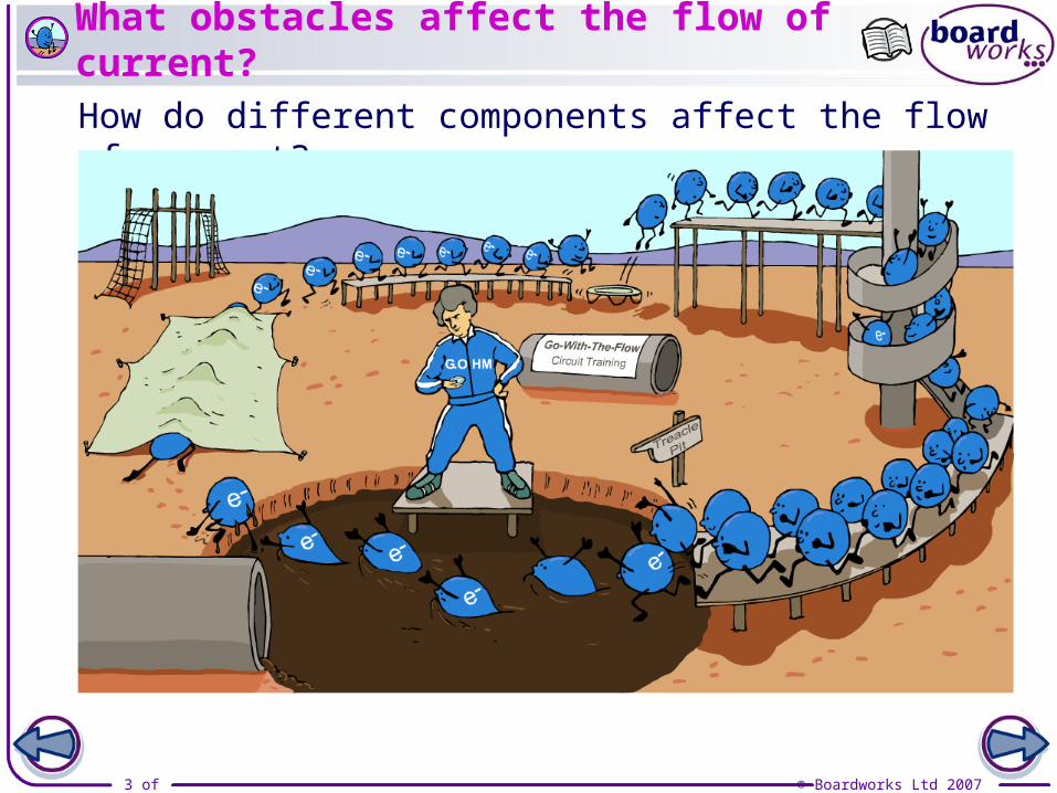
What obstacles affect the flow of current?
How do different components affect the flow of current?
4 of 46 © Boardworks Ltd 2007
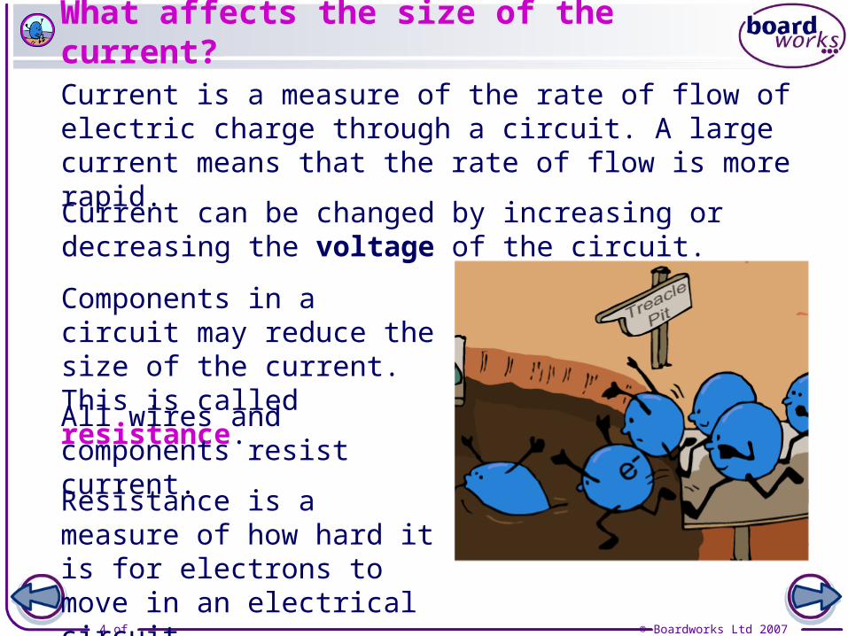
What affects the size of the current?
Current can be changed by increasing or decreasing the voltage of the circuit.
Current is a measure of the rate of flow of electric charge through a circuit. A large current means that the rate of flow is more rapid.
Components in a circuit may reduce the size of the current. This is called resistance.
All wires and components resist current.
Resistance is a measure of how hard it is for electrons to move in an electrical circuit.
5 of 46 © Boardworks Ltd 2007
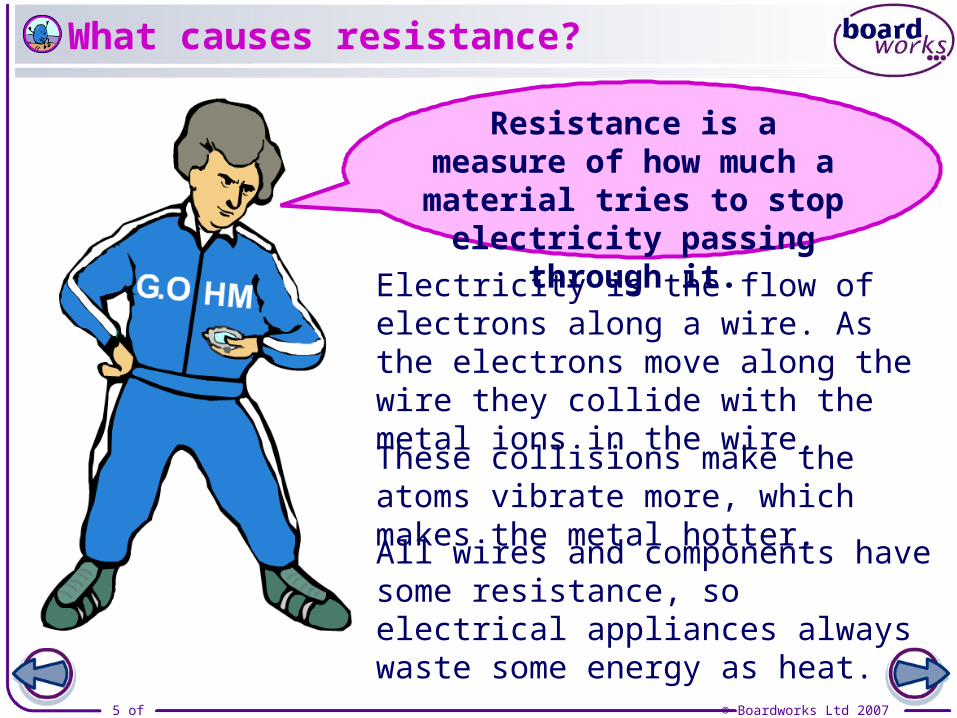
All wires and components have some resistance, so electrical appliances always waste some energy as heat.
Electricity is the flow of electrons along a wire. As the electrons move along the wire they collide with the metal ions in the wire.
These collisions make the atoms vibrate more, which makes the metal hotter.
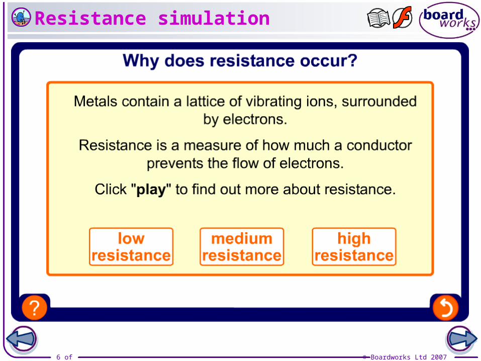
Resistance is a measure of how much a material tries to
stop electricity passing through it.
What causes resistance?
6 of 46 © Boardworks Ltd 2007
Resistance simulation
7 of 46 © Boardworks Ltd 2007
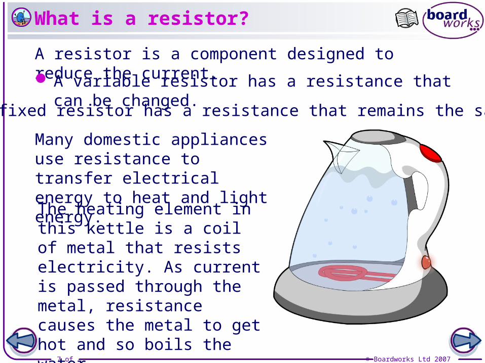
What is a resistor?
A resistor is a component designed to reduce the current.
A variable resistor has a resistance that can be changed.
A fixed resistor has a resistance that remains the same.
Many domestic appliances use resistance to transfer electrical energy to heat and light energy.
The heating element in this kettle is a coil of metal that resists electricity. As current is passed through the metal, resistance causes the metal to get hot and so boils the water.
8 of 46 © Boardworks Ltd 2007

9 of 46 © Boardworks Ltd 2007
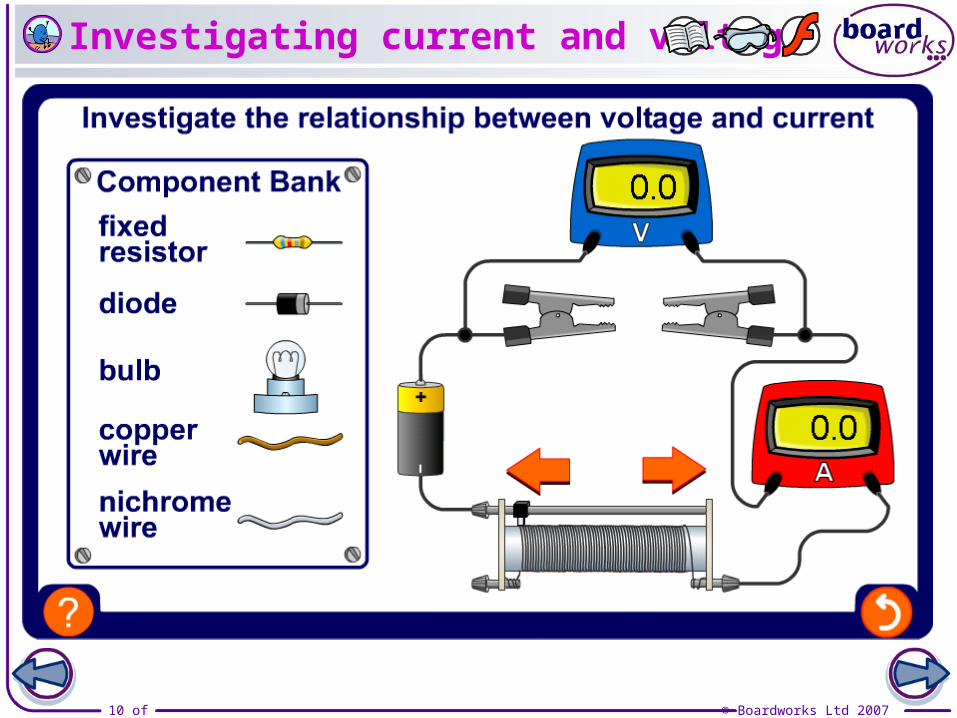
Set up this circuit with a resistor and a variable resistor.
Slowly move the variable resistor so that the voltage increases by 0.5 V and record the current for each setting.
Plot a current-voltage graph of the results.
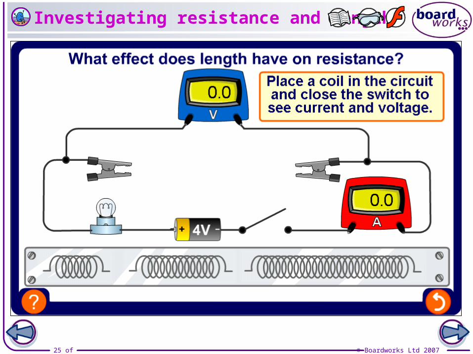
V
A
How can resistance be investigated?
voltage (V)
0.0
0.6
1.1
1.8
2.5
3.0
3.5
4.2
0.0
0.5
1.0
1.5
2.5
2.0
3.0
3.5
current (A)
10 of 46 © Boardworks Ltd 2007
Investigating current and voltage
11 of 46 © Boardworks Ltd 2007
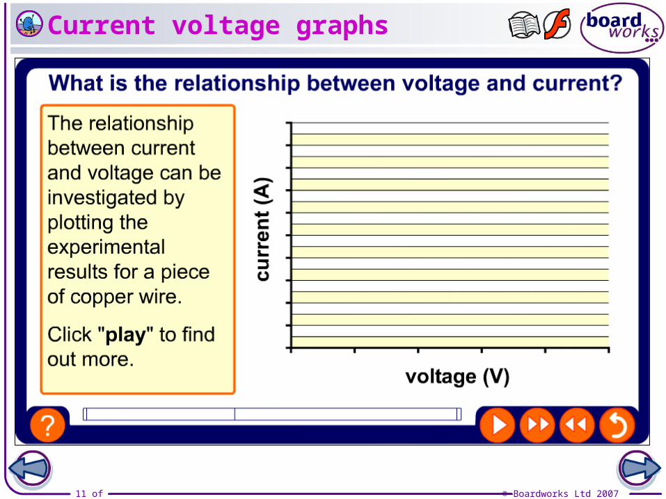
Current voltage graphs
12 of 46 © Boardworks Ltd 2007
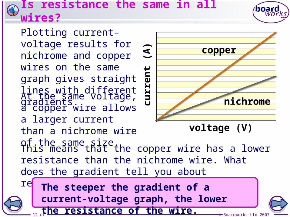
Plotting current–voltage results for nichrome and copper wires on the same graph gives straight lines with different gradients.
At the same voltage, a copper wire allows a larger current than a nichrome wire of the same size.
nichrome
copper
This means that the copper wire has a lower resistance than the nichrome wire. What does the gradient tell you about resistance?
curr
ent
(A)
voltage (V)
The steeper the gradient of a current-voltage graph, the lower the resistance of the wire.
Is resistance the same in all wires?
13 of 46 © Boardworks Ltd 2007
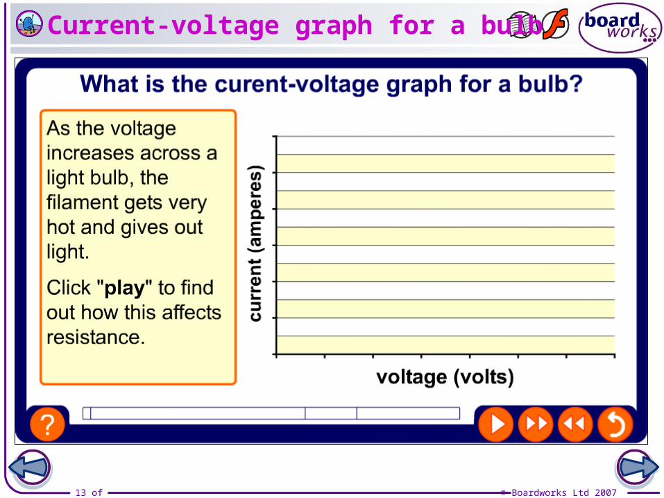
Current-voltage graph for a bulb
14 of 46 © Boardworks Ltd 2007
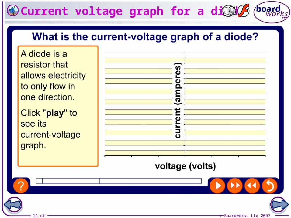
Current voltage graph for a diode
15 of 46 © Boardworks Ltd 2007
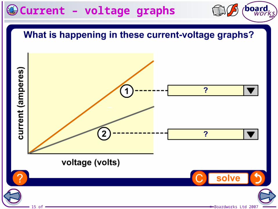
Current – voltage graphs
16 of 46 © Boardworks Ltd 2007

17 of 46 © Boardworks Ltd 2007
Resistance is a measure of how hard it is for electrons to move in an electrical circuit.
The connection between current, voltage and resistance was discovered in 1827 by Georg Ohm, a German physics and maths teacher.
The formula R = V/I is known as Ohm’s Law. It was such an important discovery in electricity that the unit of resistance is called the ohm. This unit is represented by the symbol .
The irresistible Georg Ohm

18 of 46 © Boardworks Ltd 2007
What are the units of voltage, current and resistance?
Ohm’s law is usually written as:
Voltage is measured in volts (V). Current is measured in amps (A). Resistance is measured in ohms ().
This formula can also be written as:
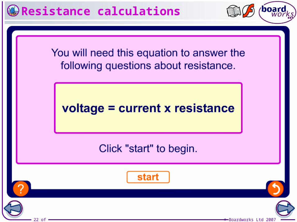
voltage = current x resistance V = I x R
resistance = R =
voltagecurrent V I
What is the formula/equation for Ohm’s law?

19 of 46 © Boardworks Ltd 2007
What does Ohm’s Law show?
What do the different arrangements of Ohm’s law show about the links between current, voltage and resistance?
V = I x R
R = V / I
I = V / R
This version of Ohm’s Law shows that as the voltage increases, the current increases. The voltage and current are proportional, while the resistance remains constant.
The voltage and current are proportional, so the resistance of a material is constant, as long as the temperature does not change.
For a low resistance material, more current is allowed to flow for a given voltage. For a high resistance material, less current will flow at the same voltage.
20 of 46 © Boardworks Ltd 2007
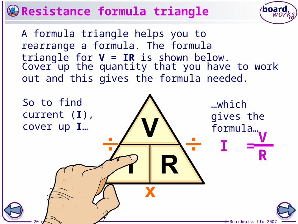
A formula triangle helps you to rearrange a formula. The formula triangle for V = IR is shown below.
Cover up the quantity that you have to work out and this gives the formula needed.
So to find current (I), cover up I…
…which gives the formula…
I =VR
x
Resistance formula triangle

21 of 46 © Boardworks Ltd 2007
A filament bulb has a current of 0.2 A running through it, with a potential difference of 5 V across it.
V = IR
Calculating the resistance of a bulb
What is the resistance of the filament in the bulb?
= 5 V 0.2 A
R = V I
= 25
22 of 46 © Boardworks Ltd 2007
Resistance calculations
23 of 46 © Boardworks Ltd 2007
24 of 46 © Boardworks Ltd 2007
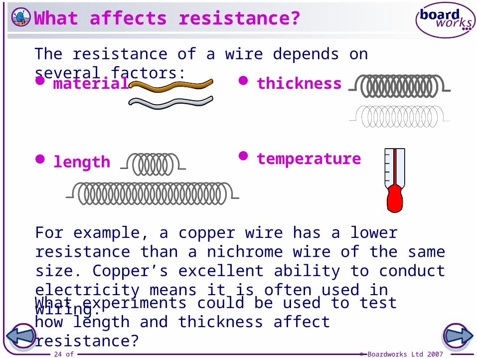
The resistance of a wire depends on several factors:
material
length
thickness
temperature
For example, a copper wire has a lower resistance than a nichrome wire of the same size. Copper’s excellent ability to conduct electricity means it is often used in wiring.
What experiments could be used to test how length and thickness affect resistance?
What affects resistance?
25 of 46 © Boardworks Ltd 2007
Investigating resistance and length
26 of 46 © Boardworks Ltd 2007
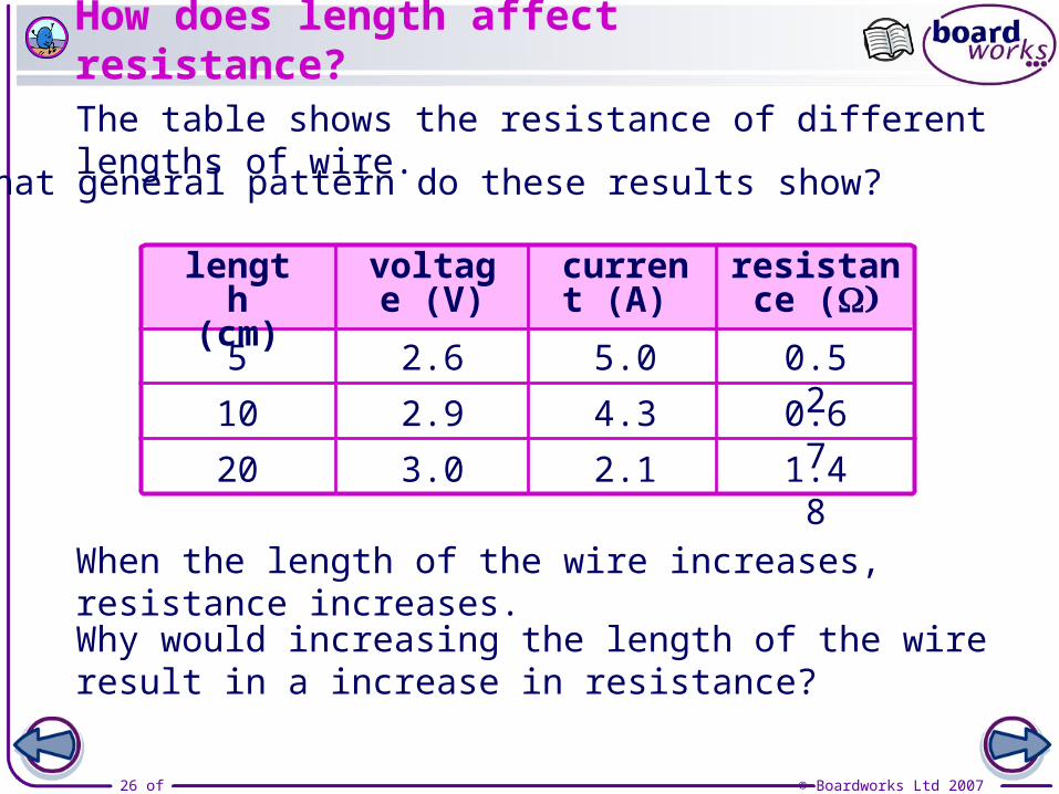
How does length affect resistance?
When the length of the wire increases, resistance increases.
The table shows the resistance of different lengths of wire.
Why would increasing the length of the wire result in a increase in resistance?
length (cm)
5
10
20
voltage (V)
current (A)
resistance (
2.6
2.9
3.0
5.0
4.3
2.1
0.52
0.67
1.48
What general pattern do these results show?
27 of 46 © Boardworks Ltd 2007
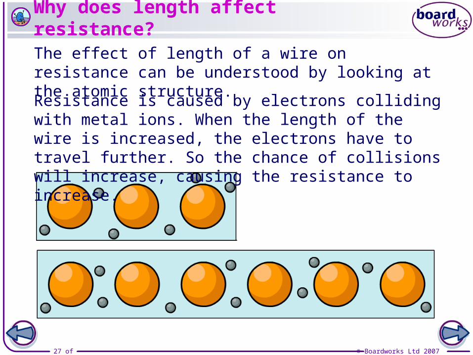
Why does length affect resistance?
The effect of length of a wire on resistance can be understood by looking at the atomic structure.
Resistance is caused by electrons colliding with metal ions. When the length of the wire is increased, the electrons have to travel further. So the chance of collisions will increase, causing the resistance to increase.
28 of 46 © Boardworks Ltd 2007
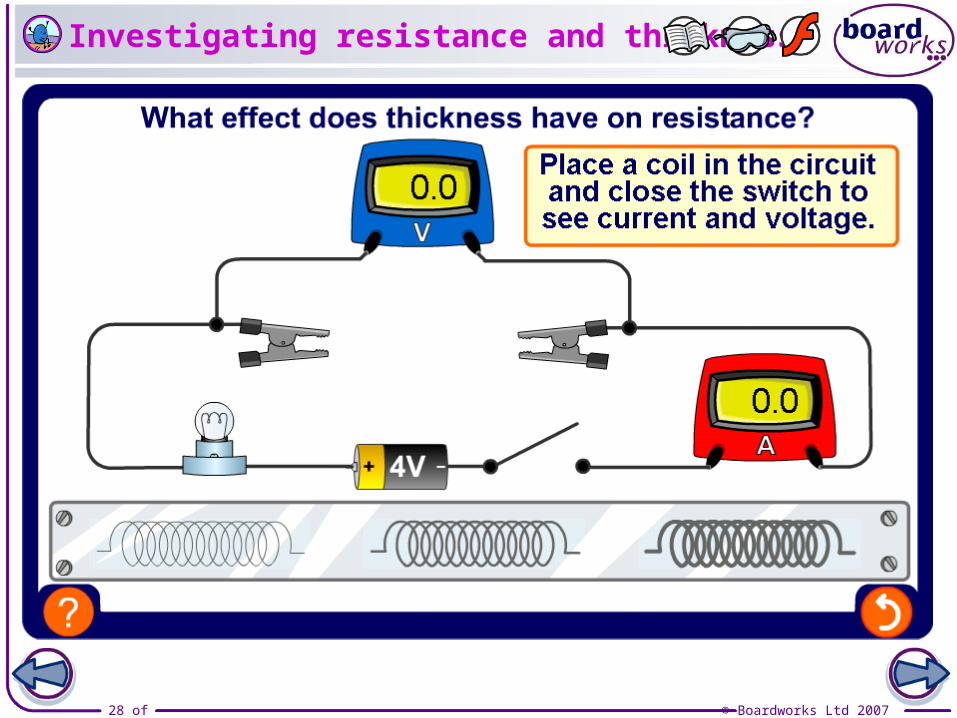
Investigating resistance and thickness

29 of 46 © Boardworks Ltd 2007
How does thickness affect resistance?
When the thickness of the wire increases, resistance decreases.
The table shows the resistance of different thicknesses of wire.
Why would increasing the thickness of the wire result in a decrease in resistance?
thickness (mm)
1
2
4
voltage (V)
current (A)
resistance (
3.0
2.9
2.6
2.1
4.3
5.0
1.48
0.67
0.52
What general pattern do these results show?
30 of 46 © Boardworks Ltd 2007
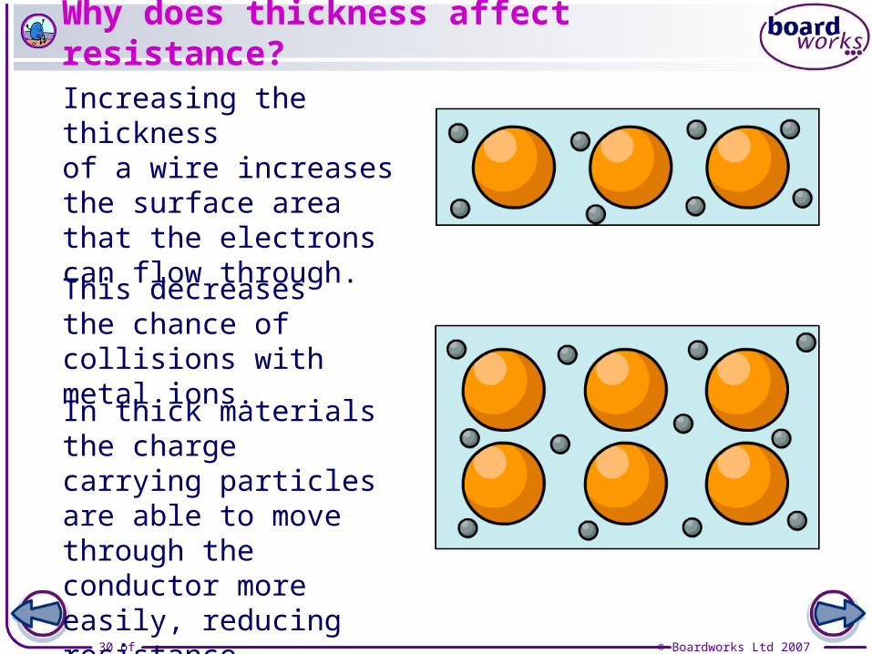
Why does thickness affect resistance?
Increasing the thickness of a wire increases the surface area that the electrons can flow through.
In thick materials the charge carrying particles are able to move through the conductor more easily, reducing resistance.
This decreases the chance of collisions with metal ions.
31 of 46 © Boardworks Ltd 2007
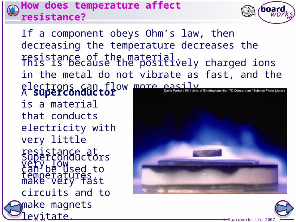
How does temperature affect resistance?
If a component obeys Ohm’s law, then decreasing the temperature decreases the resistance of the material.
A superconductor is a material that conducts electricity with very little resistance at very low temperatures.
This is because the positively charged ions in the metal do not vibrate as fast, and the electrons can flow more easily.
Superconductors can be used to make very fast circuits and to make magnets levitate.

32 of 46 © Boardworks Ltd 2007
Resistance – true or false?
33 of 46 © Boardworks Ltd 2007
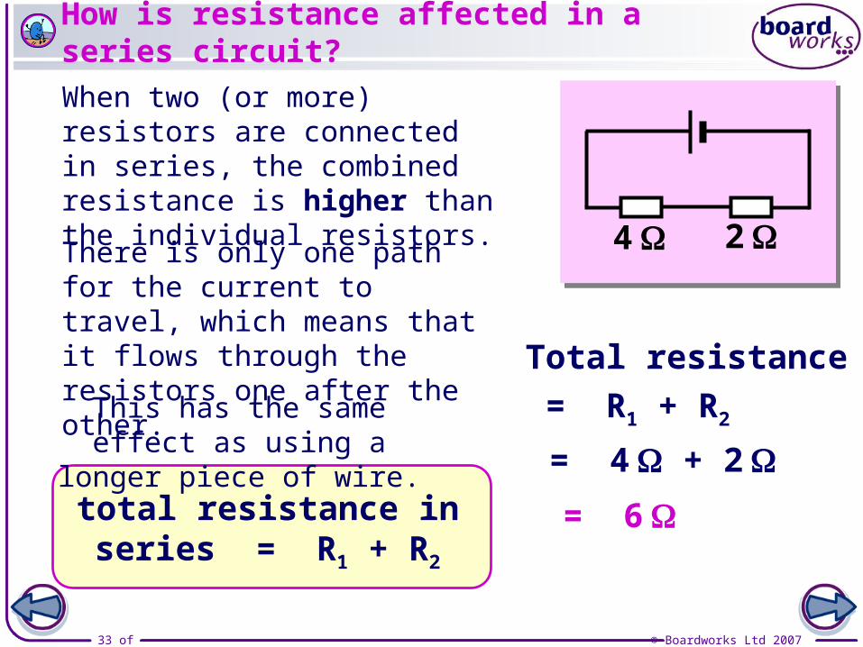
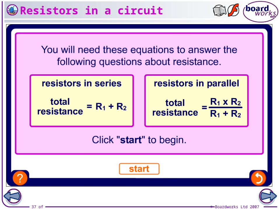
total resistance in series = R1 + R2
There is only one path for the current to travel, which means that it flows through the resistors one after the other.
When two (or more) resistors are connected in series, the combined resistance is higher than the individual resistors.
4 2
Total resistance
= R1 + R2
= 4 + 2
= 6
How is resistance affected in a series circuit?
This has the same effect as using a longer piece of wire.
34 of 46 © Boardworks Ltd 2007
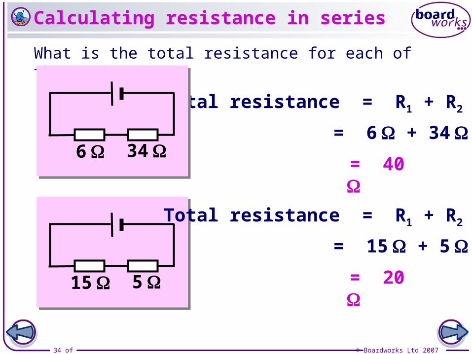
What is the total resistance for each of these circuits?
Total resistance = R1 + R2
= 6 + 34
= 40 6 34
Calculating resistance in series
15 5
Total resistance = R1 + R2
= 15 + 5
= 20
35 of 46 © Boardworks Ltd 2007
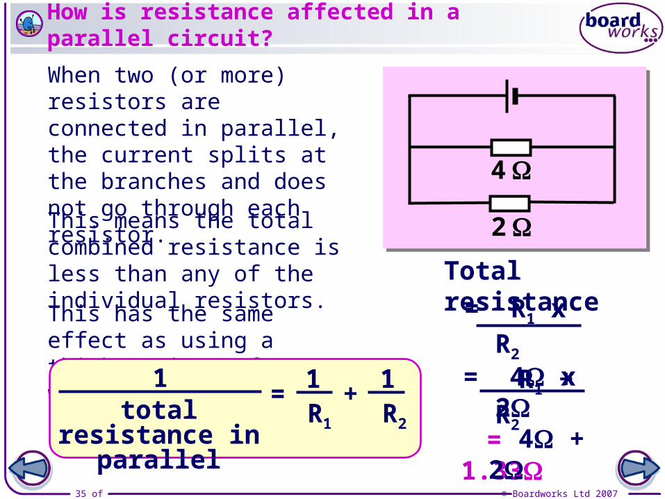
Total resistance
2
4
= 1.33
When two (or more) resistors are connected in parallel, the current splits at the branches and does not go through each resistor.
= R1 x R2
R1 + R2
= 4 x 2 4 + 2
How is resistance affected in a parallel circuit?
This has the same effect as using a thicker piece of wire.
This means the total combined resistance is less than any of the individual resistors.
1 11total resistance
in parallelR1 R2
= +

36 of 46 © Boardworks Ltd 2007
What is the total resistance for each of these circuits?
= 3.4 6
8
Total resistance = R1 x R2
R1 + R2
= 8 x 6 8 + 6
Calculating resistance in parallel
5
5
= 2.5
Total resistance = R1 x R2
R1 + R2
= 5 x 5 5 + 5
37 of 46 © Boardworks Ltd 2007
Resistors in a circuit

38 of 46 © Boardworks Ltd 2007
39 of 46 © Boardworks Ltd 2007
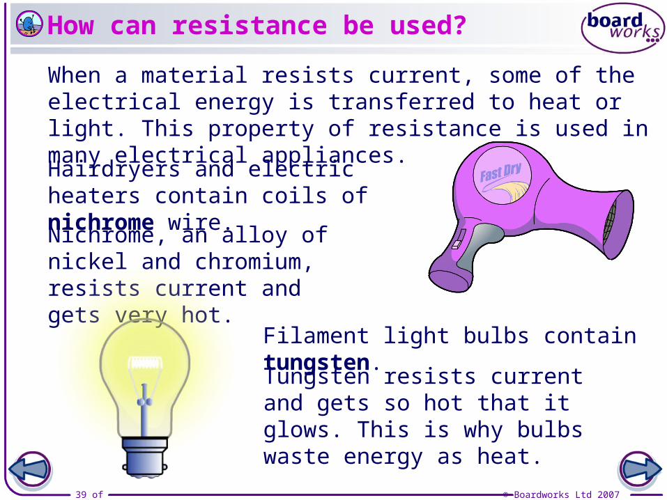
How can resistance be used?
Nichrome, an alloy of nickel and chromium, resists current and gets very hot.
When a material resists current, some of the electrical energy is transferred to heat or light. This property of resistance is used in many electrical appliances.
Tungsten resists current and gets so hot that it glows. This is why bulbs waste energy as heat.
Hairdryers and electric heaters contain coils of nichrome wire.
Filament light bulbs contain tungsten.

40 of 46 © Boardworks Ltd 2007
Uses of resistors

41 of 46 © Boardworks Ltd 2007
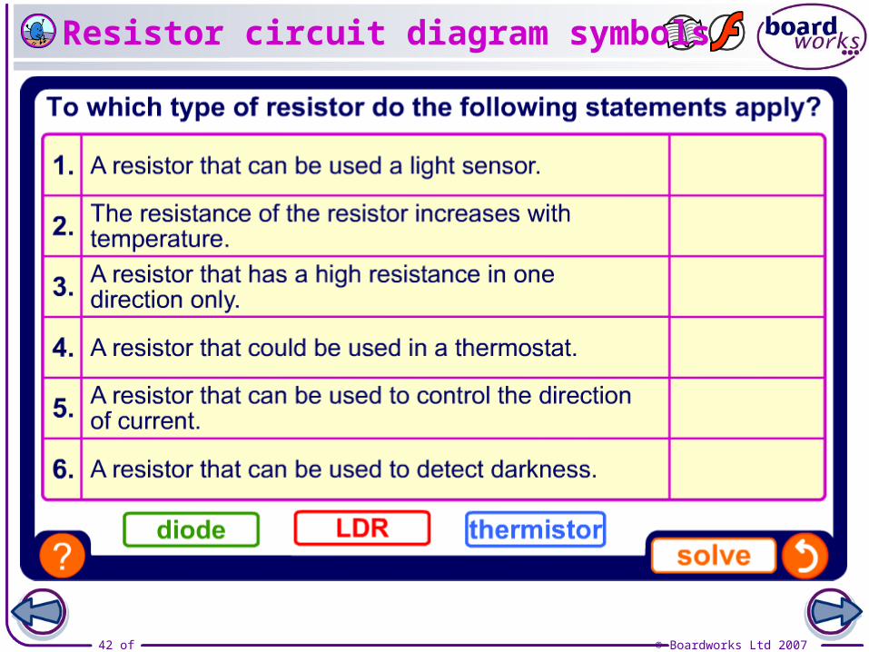
Resistor circuit diagram symbols
42 of 46 © Boardworks Ltd 2007
Resistor circuit diagram symbols
43 of 46 © Boardworks Ltd 2007
44 of 46 © Boardworks Ltd 2007
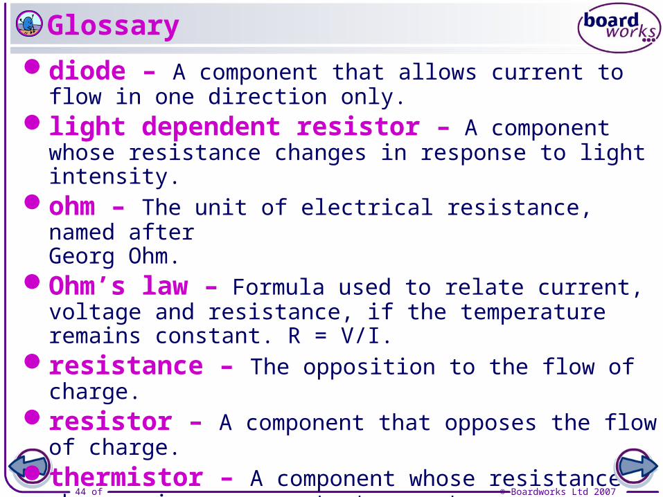
diode – A component that allows current to flow in one direction only.
light dependent resistor – A component whose resistance changes in response to light intensity.
ohm – The unit of electrical resistance, named afterGeorg Ohm.
Ohm’s law – Formula used to relate current, voltage and resistance, if the temperature remains constant. R = V/I.
resistance – The opposition to the flow of charge.resistor – A component that opposes the flow of charge. thermistor – A component whose resistance changes in
response to temperature. variable resistor – A component whose resistance can be
adjusted to vary the amount of current.
Glossary
45 of 46 © Boardworks Ltd 2007
Anagrams

46 of 46 © Boardworks Ltd 2007
Multiple-choice quiz