Embed Size (px)
Citation preview
1 of 33 © Boardworks Ltd 2009
2 of 33 © Boardworks Ltd 2009
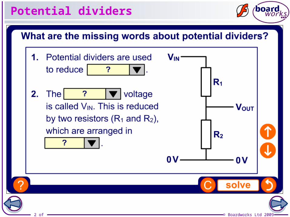
Potential dividers
3 of 33 © Boardworks Ltd 2009
4 of 33 © Boardworks Ltd 2009
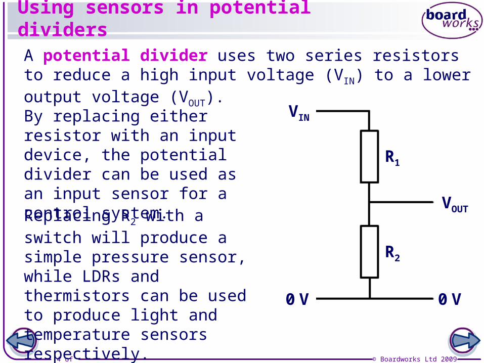
Using sensors in potential dividers
VIN
VOUT
0 V 0 V
R1
R2
By replacing either resistor with an input device, the potential divider can be used as an input sensor for a control system.
A potential divider uses two series resistors to reduce a high input voltage (VIN) to a lower output voltage (VOUT).
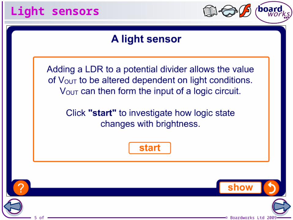
Replacing R2 with a switch will produce a simple pressure sensor, while LDRs and thermistors can be used to produce light and temperature sensors respectively.
5 of 33 © Boardworks Ltd 2009
Light sensors
6 of 33 © Boardworks Ltd 2009
7 of 33 © Boardworks Ltd 2009
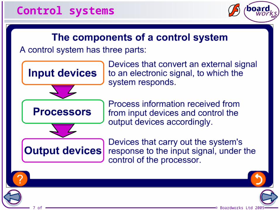
Control systems
8 of 33 © Boardworks Ltd 2009
What are logic gates?
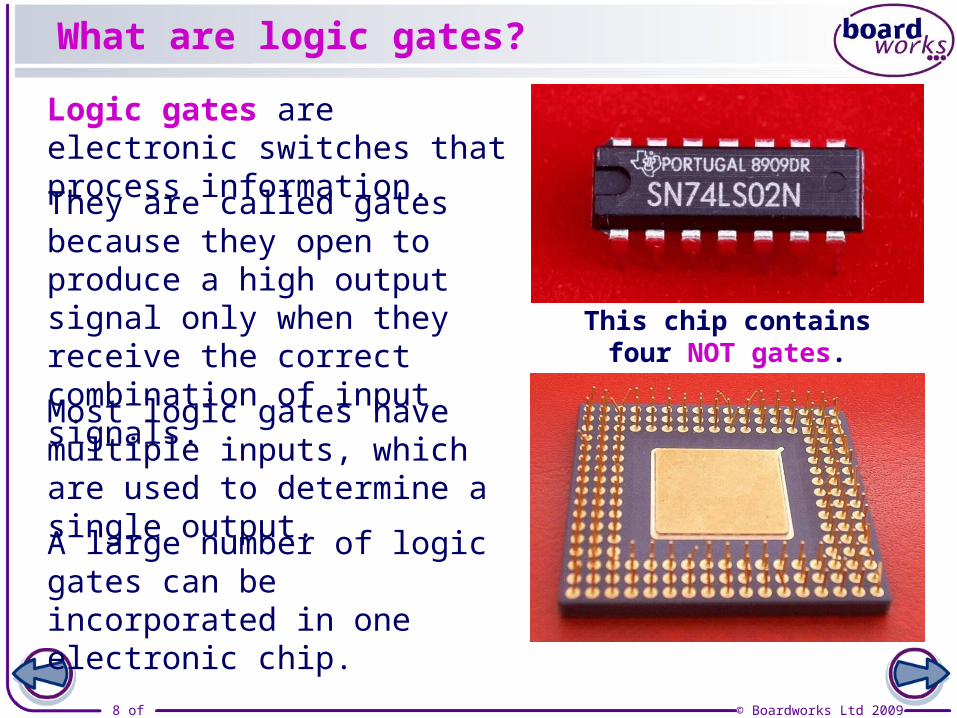
Logic gates are electronic switches that process information.
This chip contains four NOT gates.
They are called gates because they open to produce a high output signal only when they receive the correct combination of input signals.
A large number of logic gates can be incorporated in one electronic chip.
Most logic gates have multiple inputs, which are used to determine a single output.
9 of 33 © Boardworks Ltd 2009
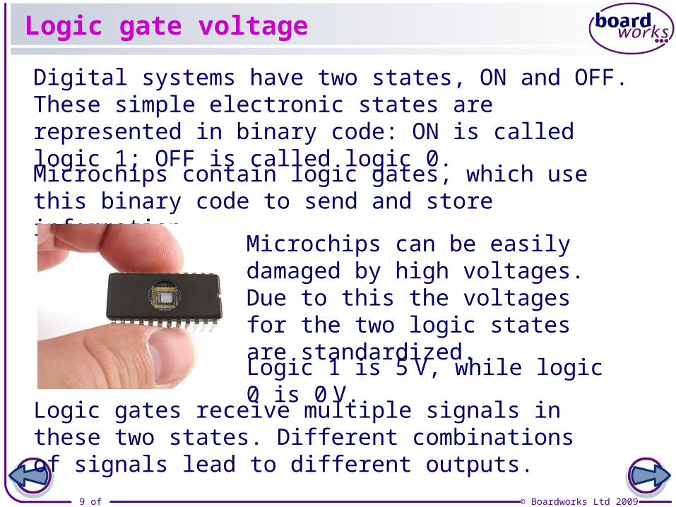
Logic gate voltage
Microchips contain logic gates, which use this binary code to send and store information.
Digital systems have two states, ON and OFF. These simple electronic states are represented in binary code: ON is called logic 1; OFF is called logic 0.
Logic gates receive multiple signals in these two states. Different combinations of signals lead to different outputs.
Microchips can be easily damaged by high voltages. Due to this the voltages for the two logic states are standardized.
Logic 1 is 5 V, while logic 0 is 0 V.
10 of 33 © Boardworks Ltd 2009
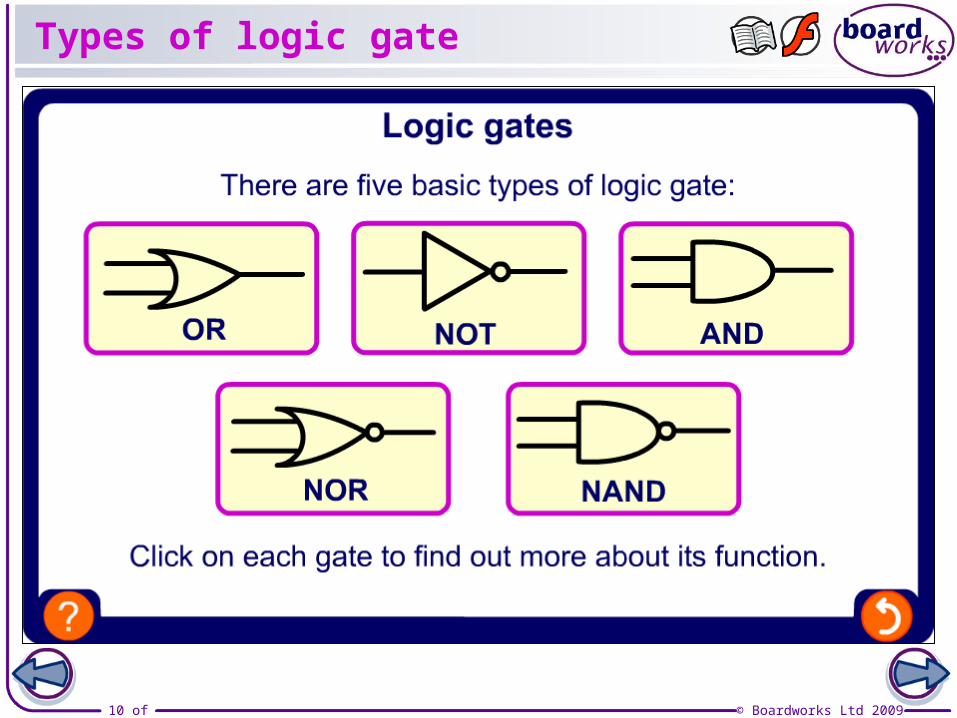
Types of logic gate
11 of 33 © Boardworks Ltd 2009
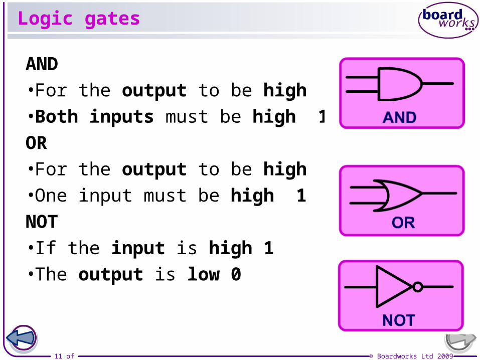
Logic gates
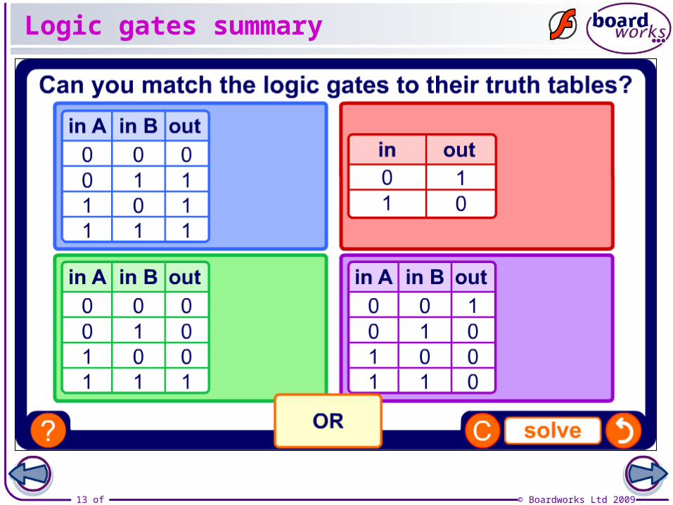
AND•For the output to be high 1•Both inputs must be high 1
OR•For the output to be high 1 •One input must be high 1
NOT•If the input is high 1 •The output is low 0
12 of 33 © Boardworks Ltd 2009
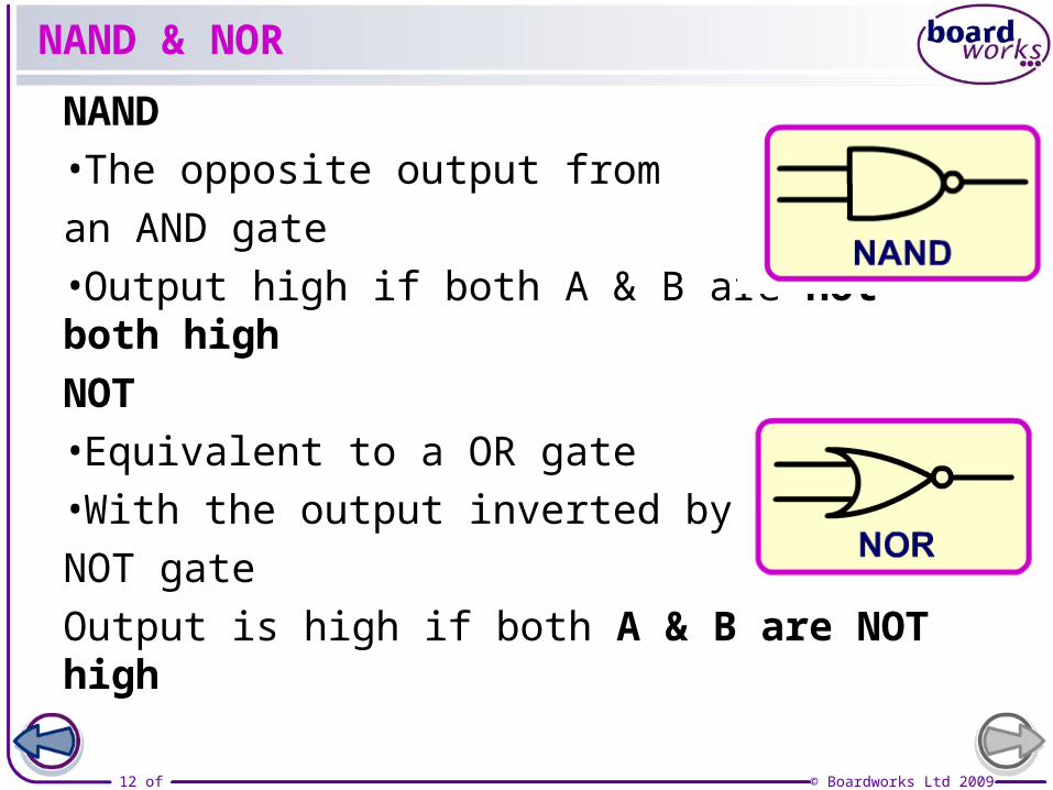
NAND & NOR
NAND
•The opposite output from
an AND gate
•Output high if both A & B are not both high
NOT
•Equivalent to a OR gate
•With the output inverted by a
NOT gate
Output is high if both A & B are NOT high
13 of 33 © Boardworks Ltd 2009
Logic gates summary
14 of 33 © Boardworks Ltd 2009
15 of 33 © Boardworks Ltd 2009
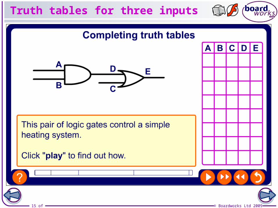
Truth tables for three inputs
16 of 33 © Boardworks Ltd 2009
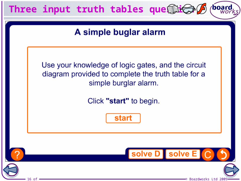
Three input truth tables question
17 of 33 © Boardworks Ltd 2009
Truth tables for four inputs
18 of 33 © Boardworks Ltd 2009
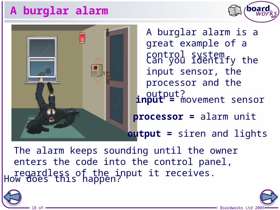
A burglar alarm
The alarm keeps sounding until the owner enters the code into the control panel, regardless of the input it receives.
Can you identify the input sensor, the processor and the output?
A burglar alarm is a great example of a control system.
input = movement sensor
processor = alarm unit
output = siren and lights
How does this happen?
19 of 33 © Boardworks Ltd 2009

20 of 33 © Boardworks Ltd 2009
Making use of logic output
There are many different output devices for an electronic system. These include motors, buzzers and lamps.
In a logic system both current and voltage are very small to prevent damaging the gates.
This limits the range of output devices which can be run on a logic system.
In order to make full use of logic systems, we must find a way to control a high voltage component using a low voltage logic system: a relay allows this.
21 of 33 © Boardworks Ltd 2009
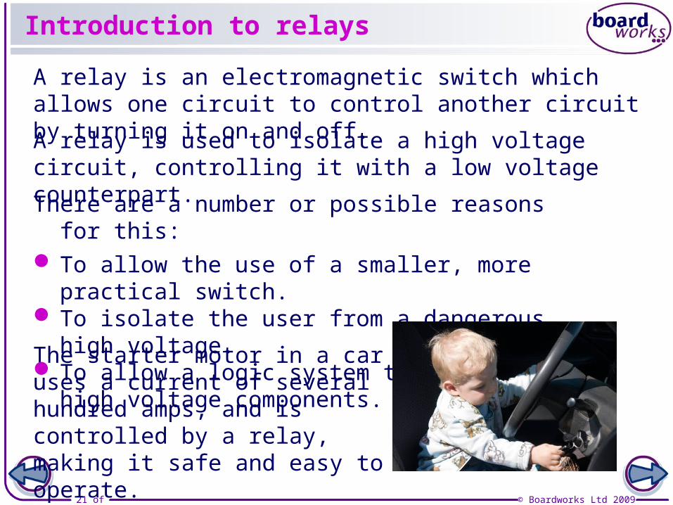
Introduction to relays
A relay is an electromagnetic switch which allows one circuit to control another circuit by turning it on and off.
The starter motor in a car uses a current of several hundred amps, and is controlled by a relay, making it safe and easy to operate.
A relay is used to isolate a high voltage circuit, controlling it with a low voltage counterpart.
There are a number or possible reasons for this: To allow the use of a smaller, more practical switch. To isolate the user from a dangerous high voltage. To allow a logic system to control high voltage
components.
22 of 33 © Boardworks Ltd 2009
How does a relay work?
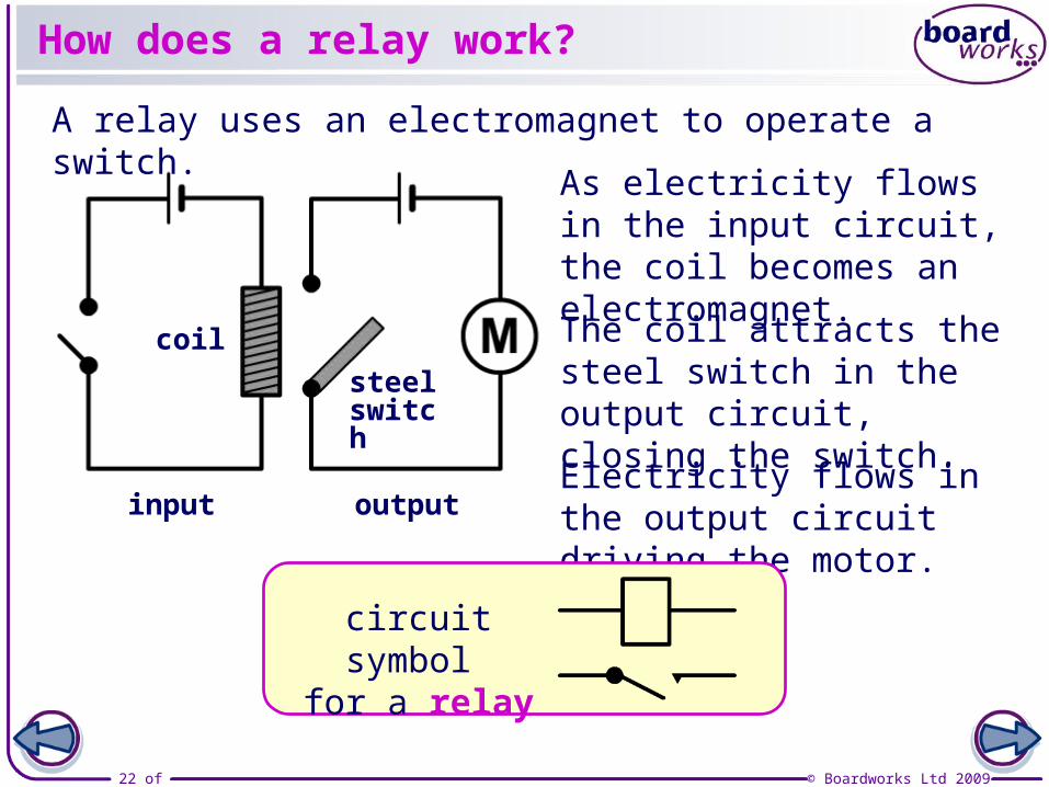
A relay uses an electromagnet to operate a switch.
As electricity flows in the input circuit, the coil becomes an electromagnet.
The coil attracts the steel switch in the output circuit, closing the switch.
Electricity flows in the output circuit driving the motor.input output
steel switch
coil
circuit symbol for a relay
23 of 33 © Boardworks Ltd 2009
Separating mains and logic voltage
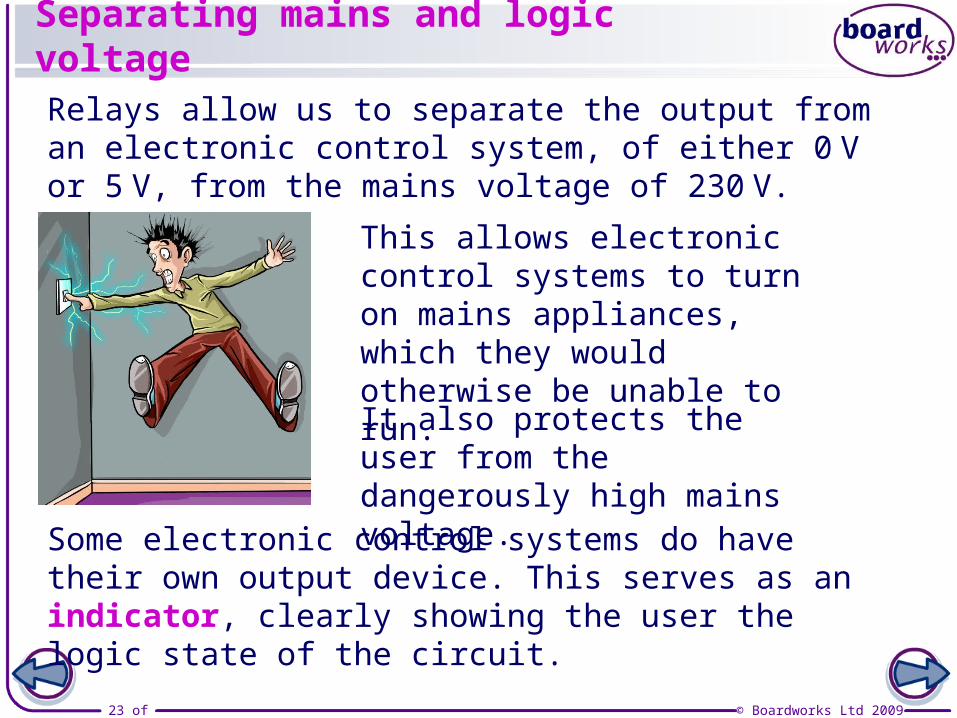
Relays allow us to separate the output from an electronic control system, of either 0 V or 5 V, from the mains voltage of 230 V.
This allows electronic control systems to turn on mains appliances, which they would otherwise be unable to run.
It also protects the user from the dangerously high mains voltage.
Some electronic control systems do have their own output device. This serves as an indicator, clearly showing the user the logic state of the circuit.
24 of 33 © Boardworks Ltd 2009
LEDs as indicators
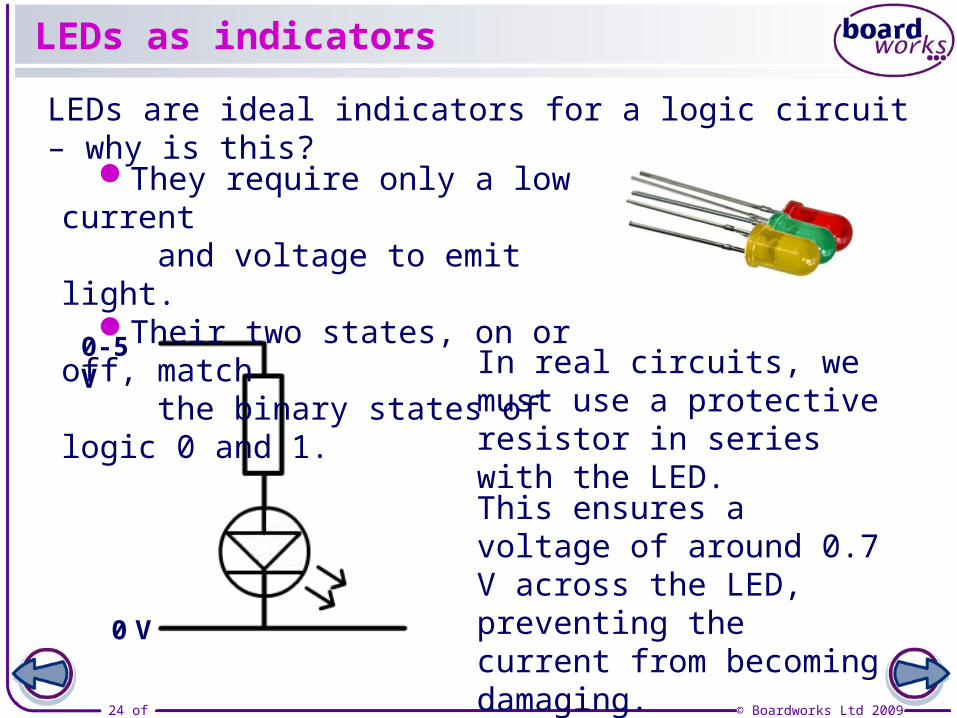
0-5 V
0 V
In real circuits, we must use a protective resistor in series with the LED.
LEDs are ideal indicators for a logic circuit – why is this?
They require only a low current and voltage to emit light.
Their two states, on or off, match the binary states of logic 0 and 1.
This ensures a voltage of around 0.7 V across the LED, preventing the current from becoming damaging.
25 of 33 © Boardworks Ltd 2009
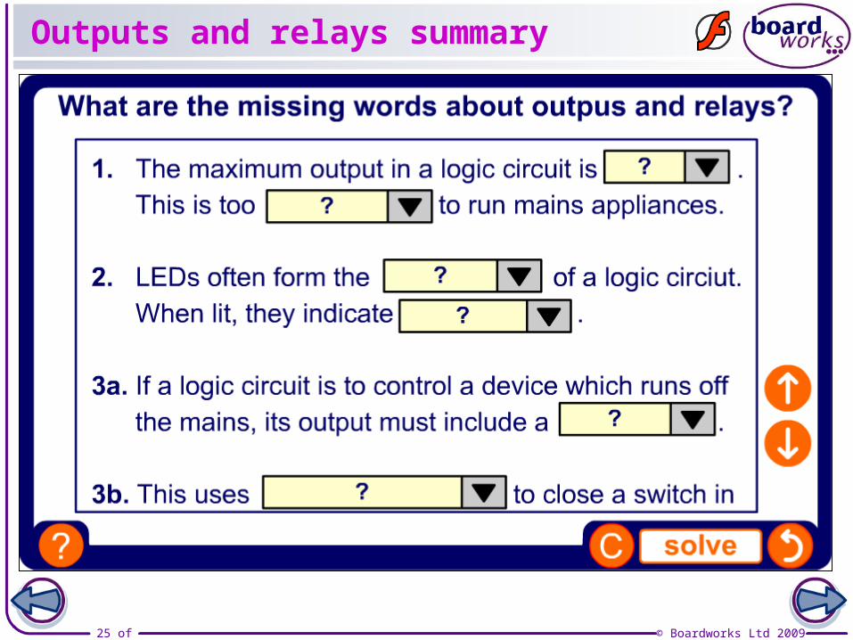
Outputs and relays summary
26 of 33 © Boardworks Ltd 2009
27 of 33 © Boardworks Ltd 2009
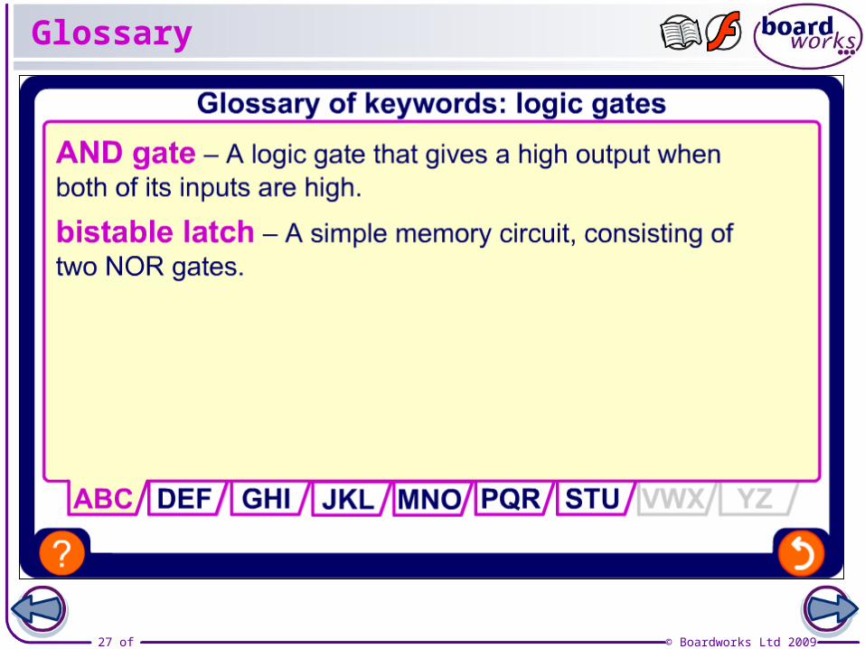
Glossary

28 of 33 © Boardworks Ltd 2009
Anagrams

29 of 33 © Boardworks Ltd 2009
Multiple-choice quiz