Embed Size (px)
Citation preview
1
NIST LBIR Capabilities for Absolute Radiometric Calibrations
Dr. Raju Datla
NIST
Optical Technology Division
Gaithersburg, MD 20899
PIs: Dr. Adriaan Carter & Dr. Timothy Jung
2
Outline
• Absolute Cryogenic radiometer (ACR) - Absolute Standard for LBIR Measurements– Blackbody Calibrations
• MDXR – LBIR Transfer Standard Radiometer– Capabilities and Possibilities
• BIB Trap detectors• Summary
3
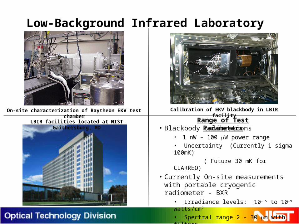
Low-Background Infrared Laboratory
• Blackbody calibrations• 1 nW – 100 W power range• Uncertainty (Currently 1 sigma 100mK)
( Future 30 mK for CLARREO)
• Currently On-site measurements with portable cryogenic radiometer - BXR
• Irradiance levels: 10-15 to 10-9 watts/cm2
• Spectral range 2 - 30 m with filters• Uncertainty: currently 3% for Missile Defense Applications.
Range of Test ParametersLBIR facilities located at NIST Gaithersburg, MD
On-site characterization of Raytheon EKV test chamber Calibration of EKV blackbody in LBIR facility
4
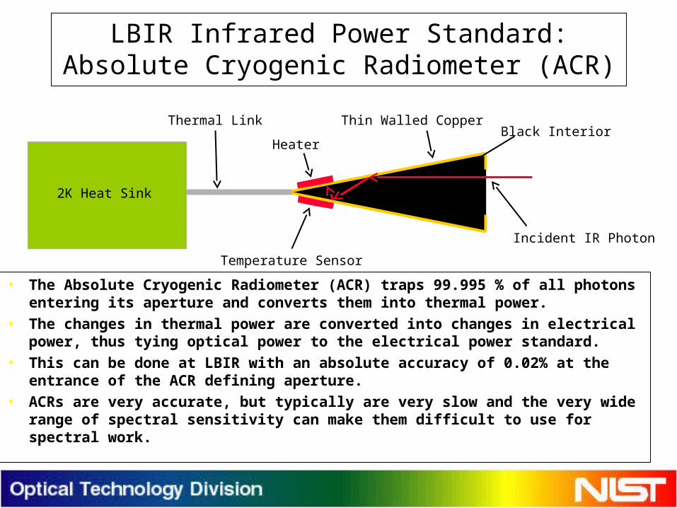
LBIR Infrared Power Standard:Absolute Cryogenic Radiometer (ACR)
• The Absolute Cryogenic Radiometer (ACR) traps 99.995 % of all photons entering its aperture and converts them into thermal power.
• The changes in thermal power are converted into changes in electrical power, thus tying optical power to the electrical power standard.
• This can be done at LBIR with an absolute accuracy of 0.02% at the entrance of the ACR defining aperture.
• ACRs are very accurate, but typically are very slow and the very wide range of spectral sensitivity can make them difficult to use for spectral work.
Thin Walled CopperBlack Interior
Temperature Sensor
Heater
Incident IR Photon
2K Heat Sink
Thermal Link
5
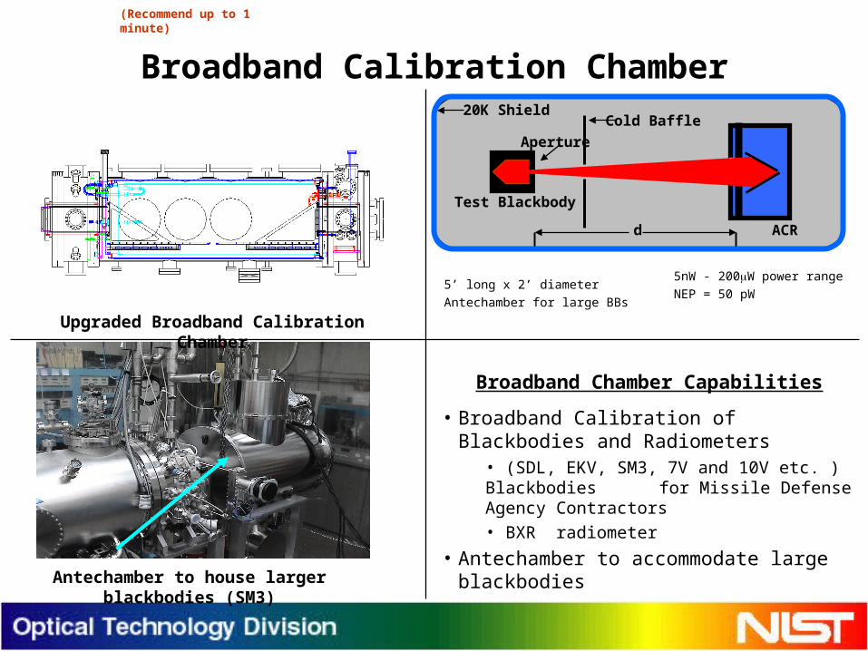
Broadband Calibration Chamber
• Broadband Calibration of Blackbodies and Radiometers
• (SDL, EKV, SM3, 7V and 10V etc. ) Blackbodies for Missile Defense Agency
Contractors• BXR radiometer
• Antechamber to accommodate large blackbodies
Broadband Chamber Capabilities
(Recommend up to 1 minute)
Antechamber to house larger blackbodies (SM3)
ACR
Test Blackbody
Cold Baffle
d
Aperture
20K Shield
5’ long x 2’ diameter
Antechamber for large BBs
5nW - 200W power range
NEP = 50 pW
Upgraded Broadband Calibration Chamber
6
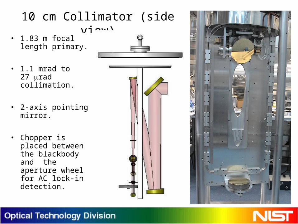
10 cm Collimator (side view)
• 1.83 m focal length primary.
• 1.1 mrad to 27 rad collimation.
• 2-axis pointing mirror.
• Chopper is placed between the blackbody and the aperture wheel for AC lock-in detection.
7
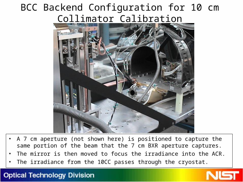
BCC Backend Configuration for 10 cm Collimator Calibration
• A 7 cm aperture (not shown here) is positioned to capture the same portion of the beam that the 7 cm BXR aperture captures.
• The mirror is then moved to focus the irradiance into the ACR.
• The irradiance from the 10CC passes through the cryostat.
8
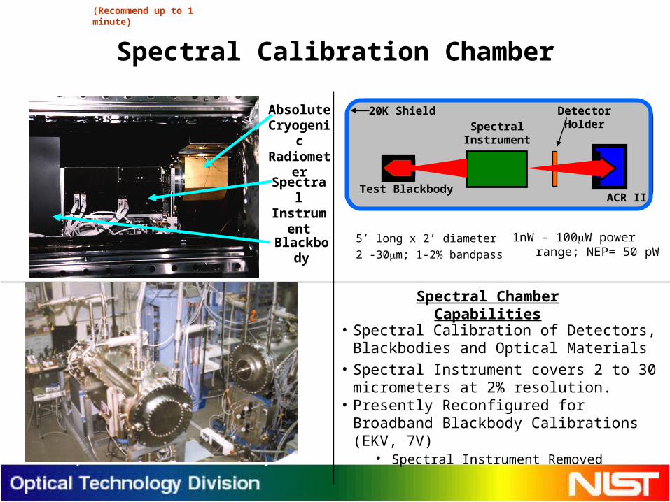
Spectral Calibration Chamber
• Spectral Calibration of Detectors, Blackbodies and Optical Materials
• Spectral Instrument covers 2 to 30 micrometers at 2% resolution.
• Presently Reconfigured for Broadband Blackbody Calibrations (EKV, 7V)
• Spectral Instrument Removed
Spectral Chamber Capabilities
(Recommend up to 1 minute)
Space Sensor Test Facility
Absolute Cryogenic
Radiometer
Spectral Instrument
Blackbody
Test BlackbodyACR II
Spectral Instrument
DetectorHolder
20K Shield
5’ long x 2’ diameter
2 -30m; 1-2% bandpass
1nW - 100W power range; NEP= 50 pW
9
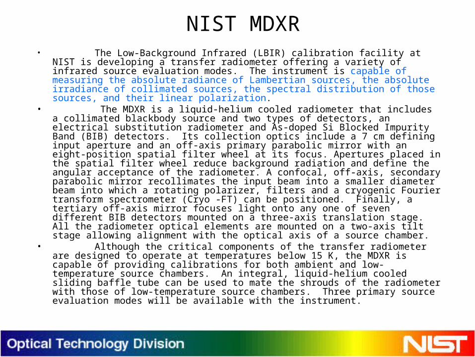
NIST MDXR• The Low-Background Infrared (LBIR) calibration facility at
NIST is developing a transfer radiometer offering a variety of infrared source evaluation modes. The instrument is capable of measuring the absolute radiance of Lambertian sources, the absolute irradiance of collimated sources, the spectral distribution of those sources, and their linear polarization.
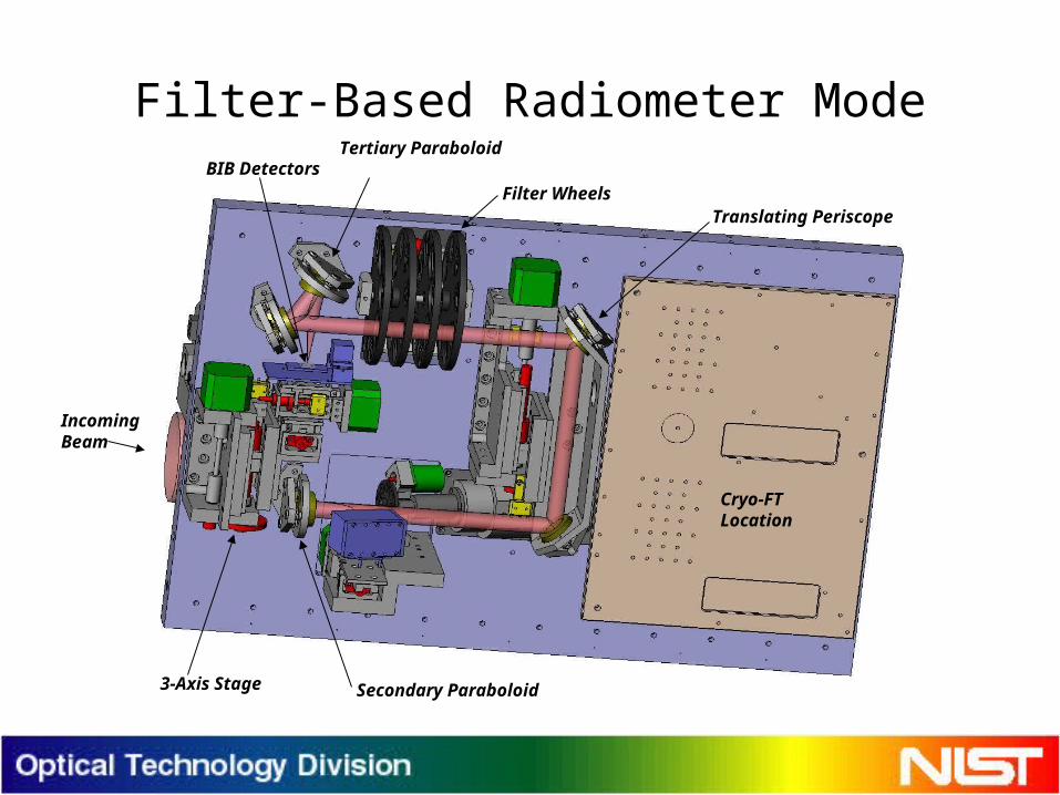
• The MDXR is a liquid-helium cooled radiometer that includes a collimated blackbody source and two types of detectors, an electrical substitution radiometer and As-doped Si Blocked Impurity Band (BIB) detectors. Its collection optics include a 7 cm defining input aperture and an off-axis primary parabolic mirror with an eight-position spatial filter wheel at its focus. Apertures placed in the spatial filter wheel reduce background radiation and define the angular acceptance of the radiometer. A confocal, off-axis, secondary parabolic mirror recollimates the input beam into a smaller diameter beam into which a rotating polarizer, filters and a cryogenic Fourier transform spectrometer (Cryo -FT) can be positioned. Finally, a tertiary off-axis mirror focuses light onto any one of seven different BIB detectors mounted on a three-axis translation stage. All the radiometer optical elements are mounted on a two-axis tilt stage allowing alignment with the optical axis of a source chamber.
• Although the critical components of the transfer radiometer are designed to operate at temperatures below 15 K, the MDXR is capable of providing calibrations for both ambient and low-temperature source chambers. An integral, liquid-helium cooled sliding baffle tube can be used to mate the shrouds of the radiometer with those of low-temperature source chambers. Three primary source evaluation modes will be available with the instrument.
10
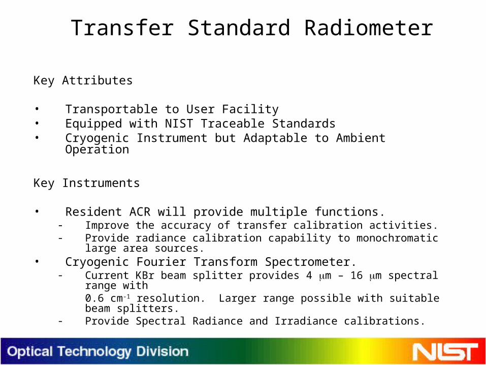
Transfer Standard Radiometer (MDXR) Key Attributes
• Transportable to User Facility • Equipped with NIST Traceable Standards• Cryogenic Instrument but Adaptable to Ambient Operation
Key Instruments
• Resident ACR will provide multiple functions.- Improve the accuracy of transfer calibration activities.- Provide radiance calibration capability to monochromatic large area sources.
• Cryogenic Fourier Transform Spectrometer.- Current KBr beam splitter provides 4 m – 16 m spectral range with
0.6 cm-1 resolution. Larger range possible with suitable beam splitters.- Provide Spectral Radiance and Irradiance calibrations.
11
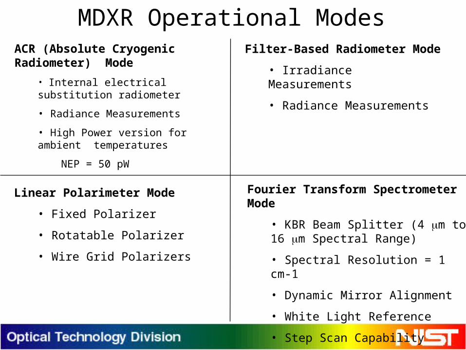
MDXR Operational Modes
Fourier Transform Spectrometer Mode
• KBR Beam Splitter (4 m to 16 m Spectral Range)
• Spectral Resolution = 1 cm-1
• Dynamic Mirror Alignment
• White Light Reference
• Step Scan Capability
ACR (Absolute Cryogenic Radiometer) Mode
• Internal electrical substitution radiometer
• Radiance Measurements
• High Power version for ambient temperatures
NEP = 50 pW
Filter-Based Radiometer Mode
• Irradiance Measurements
• Radiance Measurements
Linear Polarimeter Mode
• Fixed Polarizer
• Rotatable Polarizer
• Wire Grid Polarizers
12
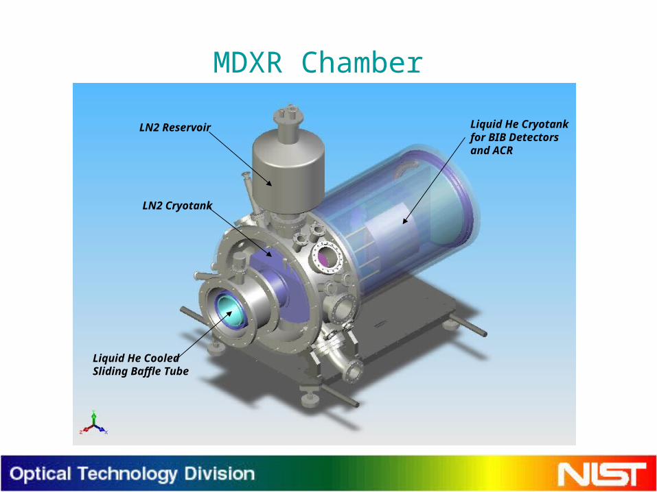
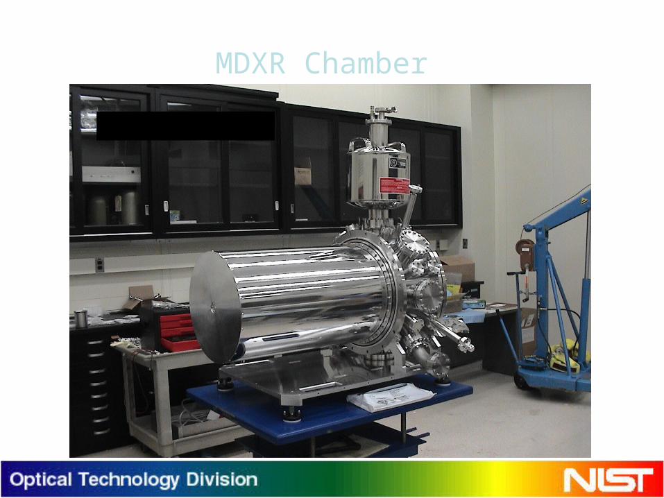
MDXR Chamber
LN2 Cryotank
LN2 Reservoir
Liquid He CooledSliding Baffle Tube
Liquid He Cryotankfor BIB Detectorsand ACR
13
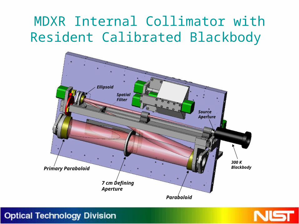
MDXR Internal Collimator with Resident Calibrated Blackbody
300 KBlackbody
Ellipsoid
Paraboloid
SpatialFilter
SourceAperture
Primary Paraboloid
7 cm DefiningAperture
14
Filter-Based Radiometer Mode
Filter WheelsTranslating Periscope
Secondary Paraboloid
Cryo-FTLocation
Tertiary ParaboloidBIB Detectors
3-Axis Stage
IncomingBeam
15
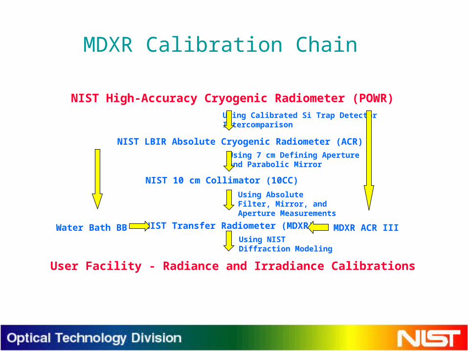
MDXR Calibration Chain
NIST High-Accuracy Cryogenic Radiometer (POWR)
NIST LBIR Absolute Cryogenic Radiometer (ACR)
Using Calibrated Si Trap Detector Intercomparison
Using 7 cm Defining ApertureAnd Parabolic Mirror
NIST 10 cm Collimator (10CC)
NIST Transfer Radiometer (MDXR) MDXR ACR IIIWater Bath BB
User Facility - Radiance and Irradiance Calibrations
Using Absolute Filter, Mirror, and Aperture Measurements
Using NIST Diffraction Modeling

16
BIB Detector Trap• Goal: Develop a new calibration standard using high internal quantum
efficiency Si:As BIB detectors in a light trapping configuration.
• Performance expectations:- NEP = 100 fW. Calibration with ACRs planned.- Faster than 0.0001 second response time (10 KHz).- No back reflection issues.
• Detector delivery expected July 20, 2008.
17
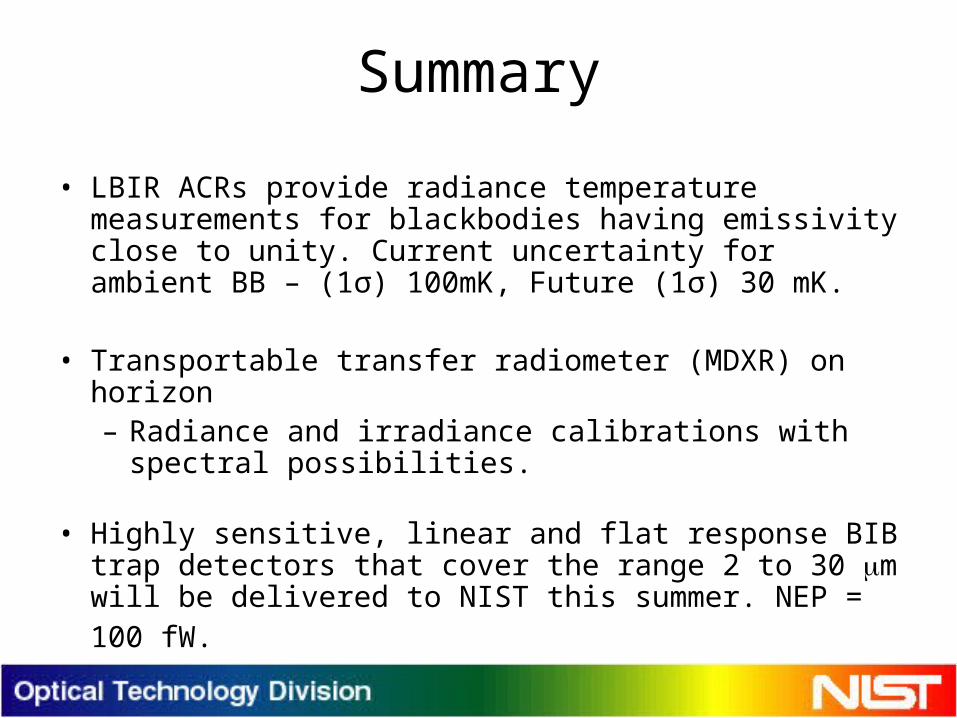
Summary
• LBIR ACRs provide radiance temperature measurements for blackbodies having emissivity close to unity. Current uncertainty for ambient BB – (1σ) 100mK, Future (1σ) 30 mK.
• Transportable transfer radiometer (MDXR) on horizon– Radiance and irradiance calibrations with spectral
possibilities.
• Highly sensitive, linear and flat response BIB trap detectors that cover the range 2 to 30 m will be delivered to NIST this summer. NEP = 100 fW.
18
Backup Slides
19
MDXR Chamber
Outer titanium chamber removed to reveal liquid nitrogen cryoshroud
20
MDXR Internal Source Assembly
An internal collimated blackbody source will be included in An internal collimated blackbody source will be included in the BXR II. The blackbody will be operated at 300 Kelvin and will the BXR II. The blackbody will be operated at 300 Kelvin and will be mounted outside the liquid helium cooled cryoshroud. be mounted outside the liquid helium cooled cryoshroud. Confocal ellipsoid and parabolic mirrors are used to create a Confocal ellipsoid and parabolic mirrors are used to create a beam with an angular divergence of less than 500 microradian beam with an angular divergence of less than 500 microradian full-cone. The 1 mm source aperture, mirrors and spatial filter are full-cone. The 1 mm source aperture, mirrors and spatial filter are mounted on a rotation stage allowing the beam to be rotated into mounted on a rotation stage allowing the beam to be rotated into the 7 cm entrance aperture of the BXR II.the 7 cm entrance aperture of the BXR II.
The internal collimated source will serve several The internal collimated source will serve several functions. As a stable reference source the beam will be used to functions. As a stable reference source the beam will be used to verify the stability of the MDXR components after shipping, as well verify the stability of the MDXR components after shipping, as well as before and after a user source chamber evaluation. As a beam as before and after a user source chamber evaluation. As a beam with a known spectral distribution, it will be used as a reference for with a known spectral distribution, it will be used as a reference for the Cryo-FT and for measuring its throughput in step mode.the Cryo-FT and for measuring its throughput in step mode.
21
Electrical-Substitution Radiometer Mode
• Internal electrical substitution radiometer for absolute radiance and irradiance measurements of both broadband and narrow band sources
• High-power version for sources at ambient temperatures– 50 pW noise floor, can measure beam irradiances
as low as 0.1 pW/cm2 with BXR II collection optics– 10 W maximum power– 2 second response time
22
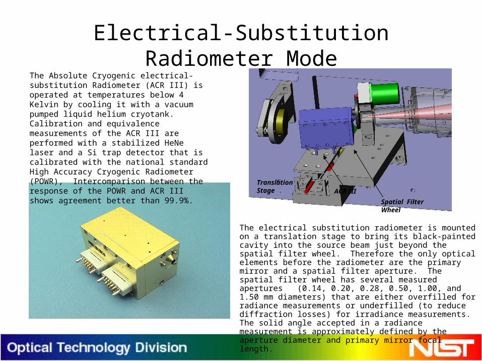
Electrical-Substitution Radiometer Mode
• The electrical substitution radiometer is mounted on a translation stage to bring its black-painted cavity into the source beam just beyond the spatial filter wheel. Therefore the only optical elements before the radiometer are the primary mirror and a spatial filter aperture. The spatial filter wheel has several measured apertures (0.14, 0.20, 0.28, 0.50, 1.00, and 1.50 mm diameters) that are either overfilled for radiance measurements or underfilled (to reduce diffraction losses) for irradiance measurements. The solid angle accepted in a radiance measurement is approximately defined by the aperture diameter and primary mirror focal length.
ACR III
Spatial FilterWheel
TranslationStage
The Absolute Cryogenic electrical-substitution Radiometer (ACR III) is operated at temperatures below 4 Kelvin by cooling it with a vacuum pumped liquid helium cryotank. Calibration and equivalence measurements of the ACR III are performed with a stabilized HeNe laser and a Si trap detector that is calibrated with the national standard High Accuracy Cryogenic Radiometer (POWR), Intercomparison between the response of the POWR and ACR III shows agreement better than 99.9%.
23
Filter-Based Radiometer Mode
• As-doped Si BIB detectors and they configured in a trap versin are the primary detectors
• Irradiance measurements– Required user source collimation O1 mrad full cone– Measures collimated beams with irradiance levels between 10-15 W/cm2 and
10-9 W/cm2 {BIBs NEP=100 femto watts)– MDXR is calibrated for these measurements using a calibrated collimator, the
NIST 10 cm Collimator (10CC)
• Radiance measurements– Can use 0.14, 0.20, and 0.28 mm diameter spatial filter apertures
corresponding to 0.38, 0.54 and 0.76 mrad full cone acceptance angles– MDXR is calibrated for these measurements using a calibrated, large area
blackbody source, the NIST LBIR Waterbath blackbody

24
MDXR Filter Set
Long-pass cut-off
wavelength (m)
Short-pass cut-off
wavelength (m)
4.798 5.266
5.786 6.254
6.779 7.247
7.790 8.258
8.740 9.208
10.730 11.198
12.406 12.874
0.0
0.2
0.4
0.6
0.8
1.0
Wavelength
Tra
nsm
issi
on
Short Pass Long Pass Combined
Long-pass and short-pass filters are placed in series to define several 300 nm wide bands. Four eight-position filter wheels hold the filters at a 3o tilt angle to prevent inter-reflections. The filters are fully characterized at 25 Kelvin and at 3o tilt angle using a FTS. In-situ measurements of the filter transmissions can be made with the Cryo-FT to investigate systematic effects..
25
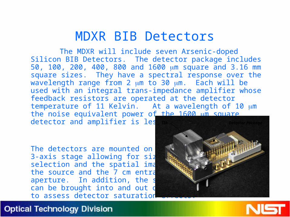
MDXR BIB DetectorsThe MDXR will include seven Arsenic-doped Silicon BIB
Detectors. The detector package includes 50, 100, 200, 400, 800 and 1600 m square and 3.16 mm square sizes. They have a spectral response over the wavelength range from 2 m to 30 m. Each will be used with an integral trans-impedance amplifier whose feedback resistors are operated at the detector temperature of 11 Kelvin. At a wavelength of 10 m the noise equivalent power of the 1600 m square detector and amplifier is less than 1 fW.
The detectors are mounted on a3-axis stage allowing for sizeselection and the spatial imaging of the source and the 7 cm entranceaperture. In addition, the sourcecan be brought into and out of focusto assess detector saturation effects.
TIA Detector Package
26
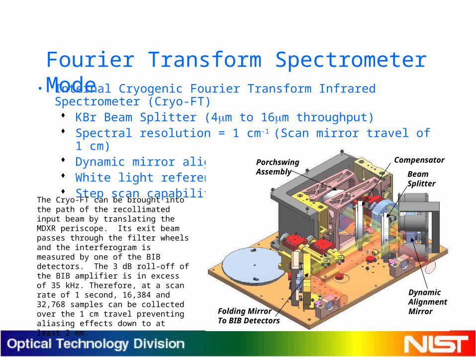
Fourier Transform Spectrometer Mode• Internal Cryogenic Fourier Transform Infrared Spectrometer (Cryo-FT)
KBr Beam Splitter (4m to 16m throughput) Spectral resolution = 1 cm-1 (Scan mirror travel of 1 cm) Dynamic mirror alignment White light reference Step scan capability
The Cryo-FT can be brought into the path of the recollimated input beam by translating the MDXR periscope. Its exit beam passes through the filter wheels and the interferogram is measured by one of the BIB detectors. The 3 dB roll-off of the BIB amplifier is in excess of 35 kHz. Therefore, at a scan rate of 1 second, 16,384 and 32,768 samples can be collected over the 1 cm travel preventing aliasing effects down to at least 2 mm.
PorchswingAssembly Beam
Splitter
Compensator
Folding MirrorTo BIB Detectors
DynamicAlignmentMirror
27
Linear Polarimeter Mode
• Rotatable polarizer placed after Mersenne telescope
• Fixed polarizer placed in filter wheel to define laboratory orientation
• Wire Grid Polarizers on ZnSe substrates Contrast ratios of 135 at 5 m and 140 at 10
m• Linear Polarization can be measured through
the complete filter set
28
MDXR Status
• Modeling Completed (2005)• Capabilities will become available in three
phases corresponding to the three primary source evaluation modes Electrical-substitution radiometer mode
(Summer 2008) Filter-based radiometer mode (Fall 2008) Fourier transform radiometer mode (Winter
2008)