Embed Size (px)
Citation preview
1
Multi - Core Multi - Core fast Communication fast Communication
for SoPC for SoPC
Technion – Israel Institute of TechnologyDepartment of Electrical EngineeringHigh Speed Digital Systems Lab
Performed by:Moshe BinoAlex Tikh
Supervisor: Evgeny Fiksman
Spring 2008
2
Single processor vs. multi-core
• Single core is reaching its performance limits: Dynamic power consumption rises linearly with freq’
Heat dissipation • ‘Power wall’ solution is keeping the frequency,
while rising the number of transistors.• Natural solution is Parallel computing• Multi-Core efficiency depends on fast comm`
between cores and network topology.
2dynamicP f C v

3
Fast communication
• Major inter-communication techniques: Shared memory
Hardware memory synchronously accessed by multiple processors to provide inter-communication through data sharing.
Remote procedure calls Inter-processors communication technology that allows one
processor to cause a subroutine or a procedure to execute in another processor’s address space.
Message passing interface (MPI) Programmable interface for advanced data passing
4
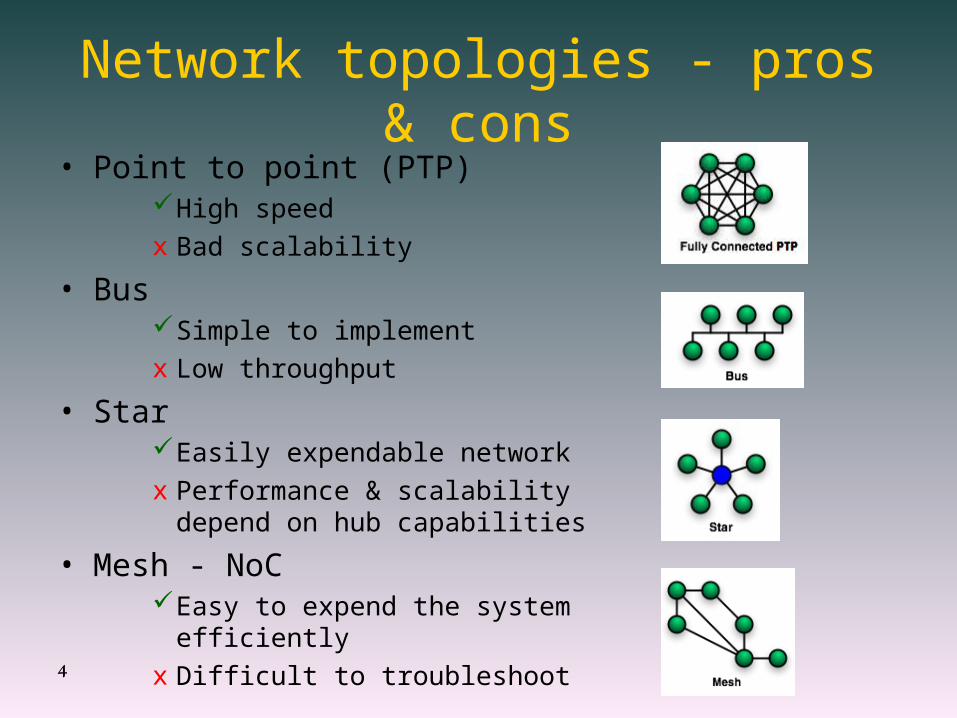
Network topologies - pros & cons• Point to point (PTP)
High speed x Bad scalability
• BusSimple to implement x Low throughput
• StarEasily expendable networkx Performance & scalability depend on
hub capabilities
• Mesh - NoCEasy to expend the system efficientlyx Difficult to troubleshoot

5
Chosen topology• Mesh topology NoC
• Routing nodes• Leaf processor’s
cores
• MPI logically defines clusters• Comm - cluster
• Rank - member
• Cores amount is limited only by chip resources
NoC is the best choice for network topology
R
#1
R
#2
R
#3
R
#4
R
#1
R
#4
R
#1
R
#2
R
#1
R
#2
R
#3
R
#2
R
#3
R
#4
R
#3
R
#4
R
R
R
R
RR RR R
Comm #1 Comm #2
Comm #3 Comm #4
FPGA
ROUTER
IP COREMODULE
BIDIRECTIONALLINK
Rank no’ in COMM
6
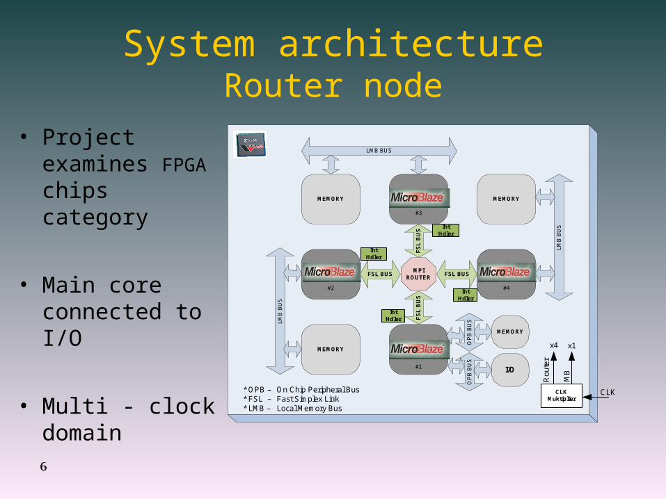
System architectureRouter node
#3
#1
#4#2
MEMORY
FSL BUS FSL BUS
FS
L B
US
FS
L B
US
MPIROUTER
LMB
BU
S
OP
B B
US
MEMORY
I/O
MEMORY
LMB BUS
MEMORY
LMB
BU
S
* OPB – On Chip Peripheral Bus* FSL – Fast Simplex Link* LMB – Local Memory Bus
OP
B B
US
CLKMuktiplier
x1x4
Ro
ute
r
MB
CLK
Int Hdler
Int Hdler
Int Hdler
Int Hdler
• Project examines FPGA chips category
• Main core connected to I/O
• Multi - clock domain

7
Logic design – Router nodeCross Bar – Low Level
Clk Rst
Req
Des
t
Prem
it
Req
Des
t
Pre
mit
Req
Dest
Premit
Req
Dest
Premit
Control B
us II
Control Bus II
Control Bus II
Permission Unit
Port
Controls3
Timer & Enable Unit
Control Bus I
Control Bus I
Data Bus 32 Bits
Data Bus 32 Bits
Data B
us
Data B
us
2
Bus I Interface Port2
Bus I Interface
Port2
Bus I Interface
Bus
I In
terf
ace
Por
t 2
Port2
Fsl_S
_Data
Fsl
_M_D
ata
Port #3 FSM
TO\FROM FSL
Bus II & Data Bus Interface
Port
2
Fsl_S_Data
Fsl_M_Data
Por
t #2
FS
M
TO
\FR
OM
FS
L
Port2
Fsl
_S_D
ata
Fsl_M
_Data
Port #1 FSM
TO\FROM FSL
Por
t2
Fsl_S_Data
Fsl_M_Data
Port #4 F
SM
TO
\FR
OM
FS
L
Port2
Bus
II &
Dat
a
Bus
Inte
rfac
e
Bus II &
Data
Bus Interface
Bus II & Data Bus Interface
Dest2
Dest
2
Dest2
Des
t2
Dest2
COMM COMM
CO
MM
CO
MM
• Time limited Round Robin arbiter.
• Port to Port & broadcasting
• Modular design
• Two main units:1. Permission Unit
2. Port FSM
8
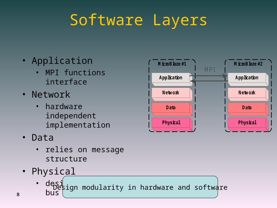
Software Layers
• Application• MPI functions interface
• Network• hardware independent
implementation
• Data• relies on message
structure
• Physical• designed for FSL bus
Design modularity in hardware and software
MicroBlaze #2MicroBlaze #1
Physical
Data
Network
Application
MPI
Physical
Data
Network
Application

9
Message transfer in progress
MicroBlaze #2MicroBlaze #1
Physical
Data
Network
ApplicationMPI
Physical
Data
Network
Application
Software Synchronization
• Parallelism:• Several messages traverse in
the system simultaneously
• Keep network clean:• Processor forced to receive
incoming message
• Ease network load:• Maintenance:
• False/error messages dismissed locally by software
• Synchronization:• Each processor DB
synchronized locally by software
R
MicroBlaze #1
Application
Network
Data
Physical
MicroBlaze #1
Application
Network
Data
Physical
MicroBlaze #1
Application
Network
Data
Physical
MicroBlaze #1
Application
Network
Data
Physical

10
System development –Project workflow
HardwareTest and Simulate
SoftwareTest and Simulate
• Hardware –• Simulation environment
• Message generator
• Software –• Development environment
• Timing
textR
Gen
Gen
Gen
Gen
HW – Simulation Env.
Core# 1
SW – Development Env.
Router
Core# 2
Exam
ines co
mm
. pro
toco
lsan
d n
etwo
rk top
olo
gies
Sin
gle co
re basic system
learn
ing
HW
& S
W stan
dalo
ne d
esign
d
evelop
men
t
Research and planSTEP 1
ImplementationSTEP 2
Desiredresult
t

11
System verification & integration
HardwareTest and Simulate
SoftwareTest and Simulate
Software& Hardware
Debug & Synth & PAR
• Send messages with different lengths
• Measure time - statistics
• Scalable application to
measure network efficiency/ performance
OptimizationPerformance App.
Exam
ines co
mm
. pro
toco
lsan
d n
etwo
rk top
olo
gies
Sin
gle co
re basic system
learn
ing
HW
& S
W stan
dalo
ne d
esign
d
evelop
men
t
Research and planSTEP 1
ImplementationSTEP 2
System integration & verificationSTEP 3
HW
& S
W In
tegratio
n
Ru
n T
est Ap
p. &
Op
timize
System
Desiredresult
t
12
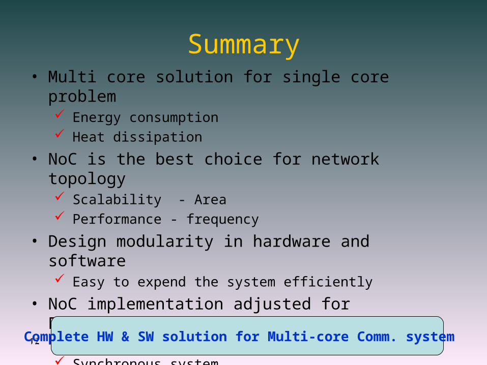
Summary• Multi core solution for single core problem
Energy consumption Heat dissipation
• NoC is the best choice for network topology Scalability - Area Performance - frequency
• Design modularity in hardware and software Easy to expend the system efficiently
• NoC implementation adjusted for FPGA platform Minimal lines and logic units Synchronous system
Complete HW & SW solution for Multi-core Comm. system

13
References[1] I.Cidon & I.Keidar: Zooming in on Network on Chip
Architectures.
[2] E.Bolotin: NoC clubnet presentation.