Embed Size (px)
Citation preview

1
Model Driven Development

2
DoDAF/ModAF/ SysML and AP233
• Architecture– DODAF
• MODAF
• Modelling– UML– SysML
• Interchange– AP 233 – XMI

3
DoDAF
• Architecture: – “The structure of components, their relationships and
the principles and guidelines governing their design and evolution over time. “ DoD
• Public Documents– Volume 1 Architectural Framework– Volume 2 Product Description – Deskbook

4
3 views
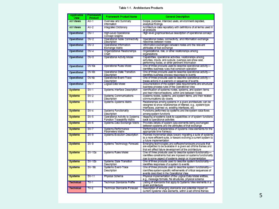
5
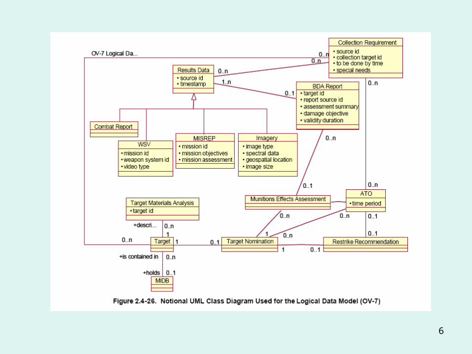
6

7
UML 1.4
• Version of Unified Modelling language in most widespread use
• Wide set of support tools:– IBM/Rational Rose, Telelogic Tau, System Architect, QSEE..
• Arises from Object-Oriented Software development– Previously data and code were kept separate, objects combine
the two– Software objects mimic real world things– Objects have a type or class
• Viewpoints– Structure
• Class; object; component ; deployment – Behaviour
• Use case; state-chart; sequence; collaboration; activity
8
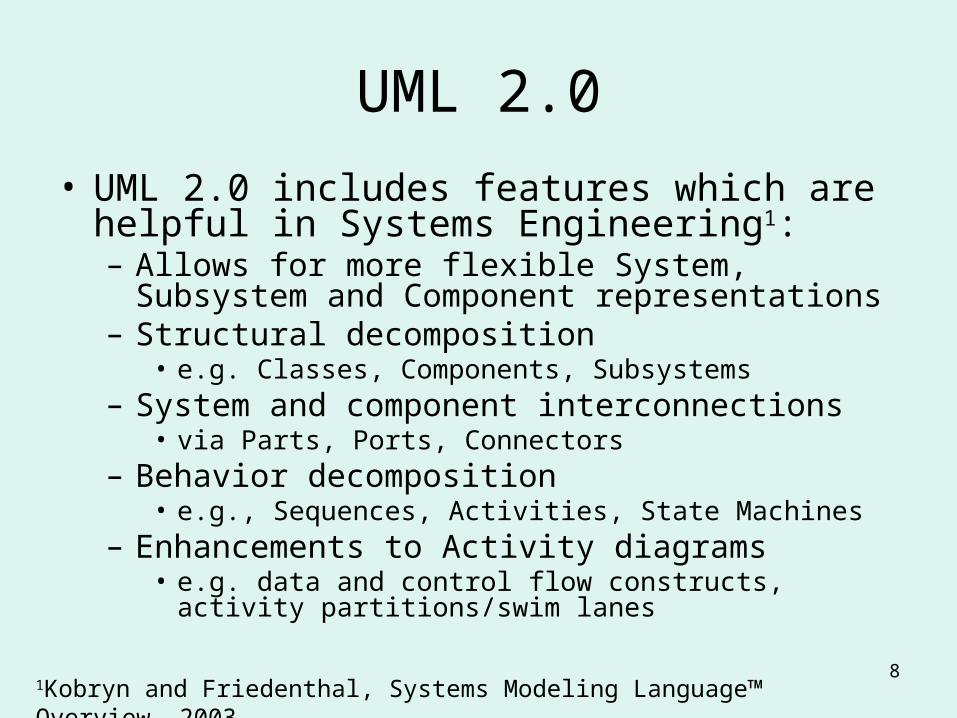
UML 2.0
• UML 2.0 includes features which are helpful in Systems Engineering1:– Allows for more flexible System, Subsystem and
Component representations– Structural decomposition
• e.g. Classes, Components, Subsystems– System and component interconnections
• via Parts, Ports, Connectors– Behavior decomposition
• e.g., Sequences, Activities, State Machines– Enhancements to Activity diagrams
• e.g. data and control flow constructs, activity partitions/swim lanes
1Kobryn and Friedenthal, Systems Modeling Language™ Overview, 2003
9
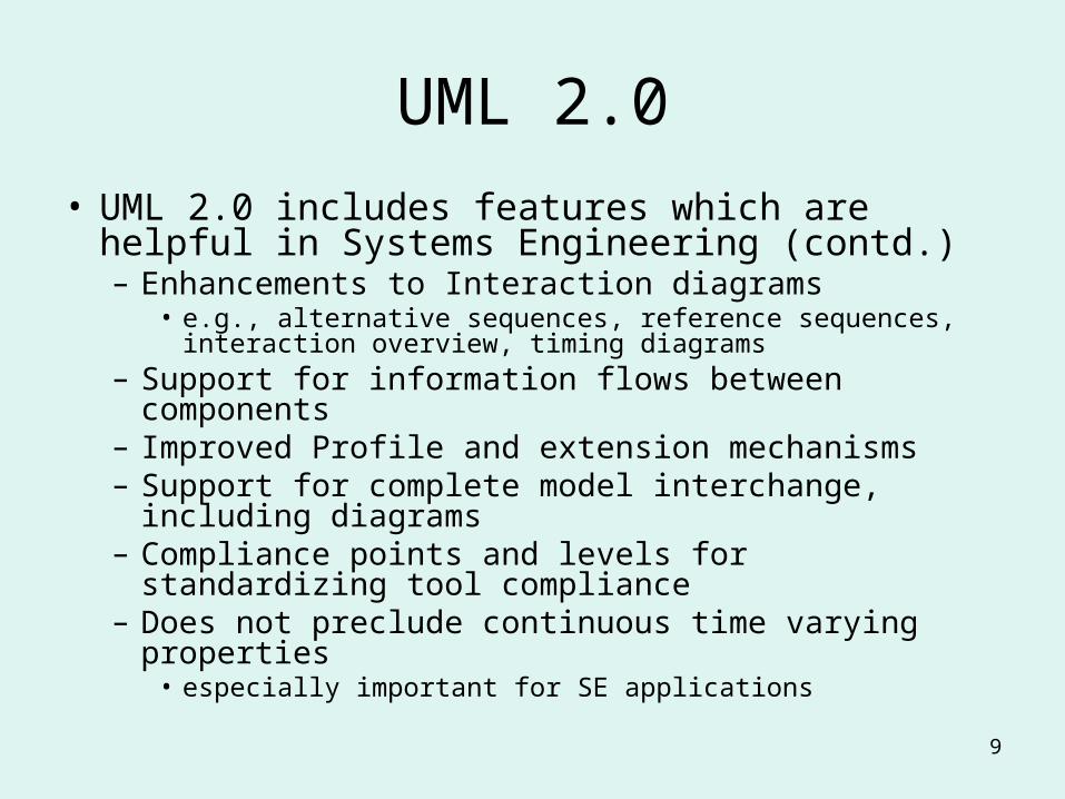
UML 2.0
• UML 2.0 includes features which are helpful in Systems Engineering (contd.) – Enhancements to Interaction diagrams
• e.g., alternative sequences, reference sequences, interaction overview, timing diagrams
– Support for information flows between components– Improved Profile and extension mechanisms– Support for complete model interchange, including
diagrams– Compliance points and levels for standardizing tool
compliance– Does not preclude continuous time varying properties
• especially important for SE applications

10
SysML origins• Systems Engineering requirements
– Hierarchic levelling of detail– Functional decomposition: Function block diagrams– Physical interaction and continuous connections– Requirements – system relationship– Mathematical models
• Main authors– Cris Kobryn and Sandy Friedenthal (SysMl partners (www.SysML.org)
• Support from – Object Management Group– Tool vendors
• Artisan, Telelogic, IBM/Rational, I-Logix– INCOSE– Industry
• BAE SYSTEMS, Deere & Company, Lockheed Martin, Motorola, Northrop Grumman, Raytheon, Thales
• Now at Draft 0.9
11
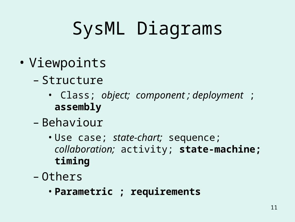
SysML Diagrams
• Viewpoints– Structure
• Class; object; component ; deployment ; assembly
– Behaviour • Use case; state-chart; sequence; collaboration;
activity; state-machine; timing
– Others• Parametric ; requirements

12
SysML Example
• Vehicle system – The problem is derived from a marketing
analysis which indicated the need to increase the acceleration of the vehicle form its current capability.
– Appendix B of the Draft standard

13
Concept Diagram
stereotype
14
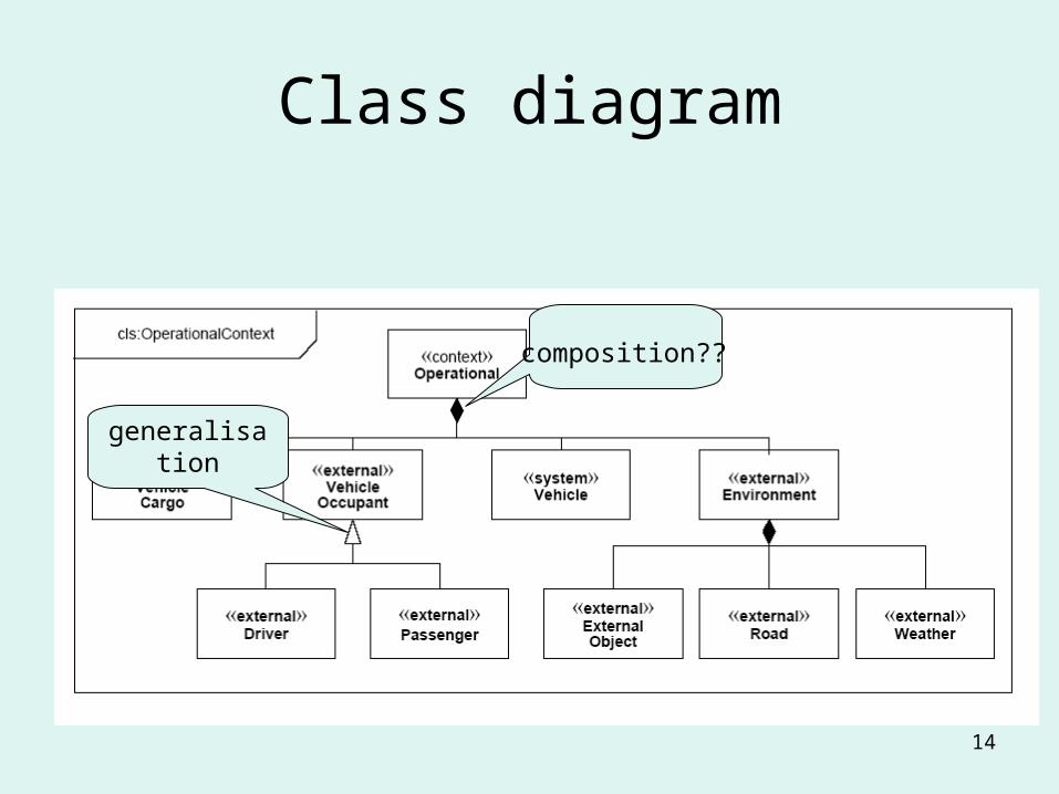
Class diagram
generalisation
composition??
15
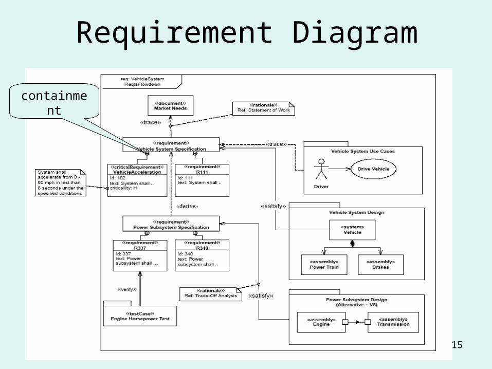
Requirement Diagram
containment

16
Use case diagramactor Use case
Sub use case
Optional extension

17
Activity Diagraminitial
final
fork
merge
decision
join
Sub-activity

18
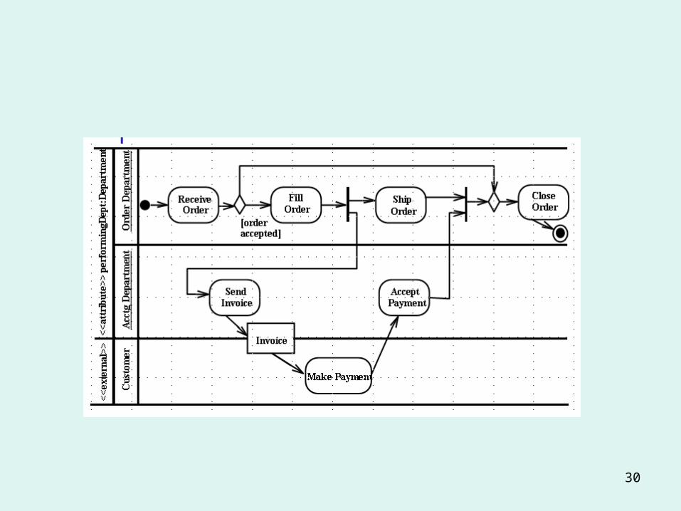
Activity Diagram
Swimlane(actor)
signal
action
object

19
Class Diagram
Data property
Physical property
operation
association
association with flow

20
State Machine Diagram
Initial
final
state
event
transition
guard
state

21
Class Diagram
Exclusive sub-
assembly
Meta data

22
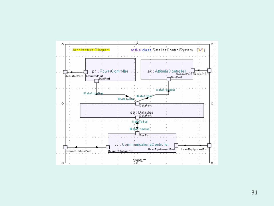
Assembly Diagram
port
connector Connector type

23
Assembly Diagramswimlane
connection stereotype
24
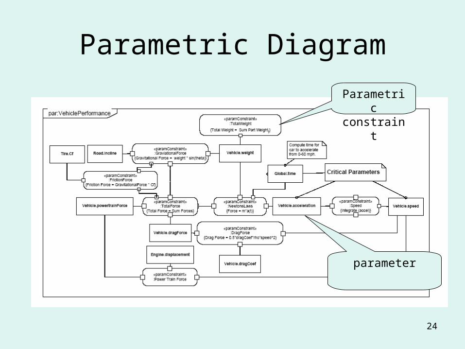
Parametric Diagram
Parametric constraint
parameter

25
: Timing Diagram
26
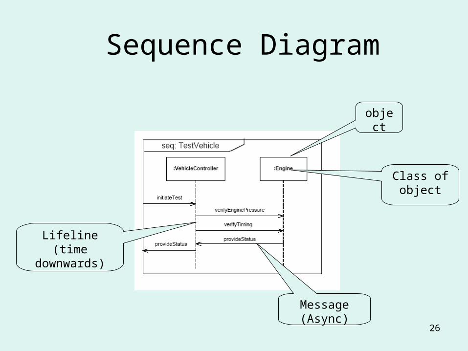
Sequence Diagram
object
Class of object
Message(Async)
Lifeline(time
downwards)

27
Sequence Diagram
Sub sequence

28
Issues
• Diagrams are not enough– Limited expressive power– Limited scope for verification
• Formal languages e.g.– OCL (Object Constraint Language)– Alloy from MIT
– Comprehension – Construction
• Patterns and Problem Frames– Knowledge representation and reuse – Problem Frames (Jackson)
Employee
1
0..*
manager

29
Workshop
• 1 – Comprehension – What do these diagrams mean in English?
• 2 – Construction– Look at the collection of simple diagrams
taken form various texts and papers• Identify which kind of diagram most closely
matches each diagram• Take on diagram and re-write as a SysML diagram
30
31
32
State machines in SysML
• 15 July 2004 – I-Logix announce that BAe systems are standardising on Statemate for development of Eurofigher Typhoon
• - using MDD – Model-driven Development
• Dec 14 2004 Statemate chosen for use by MBDA in the development of METEOR

33
Model–driven Development
• Design behaviour using diagrammatic notations
• Demonstrate and evaluate the behaviour early in the development process
• Generate the delivered code/part directly from the model, perhaps guided by the designer with additional decisions.

34
Statemate
• A state machine design tool based on David Harel’s state charts (incorporated into UML)
• Allows– Simulation – what would happen if the
following sequence of events occurred.– Analysis – prove that the system can never
lock up– Code generation – to C for loading into
embedded processors

35
Basic State Machine
• The basic concepts in this notation are:– state
• A mode of the object/component/sub-system
– transition • A change of state caused by an event or input,
perhaps back to the same state
– event• the input which causes a transition to occur
– action• An action which occurs when a transition is made
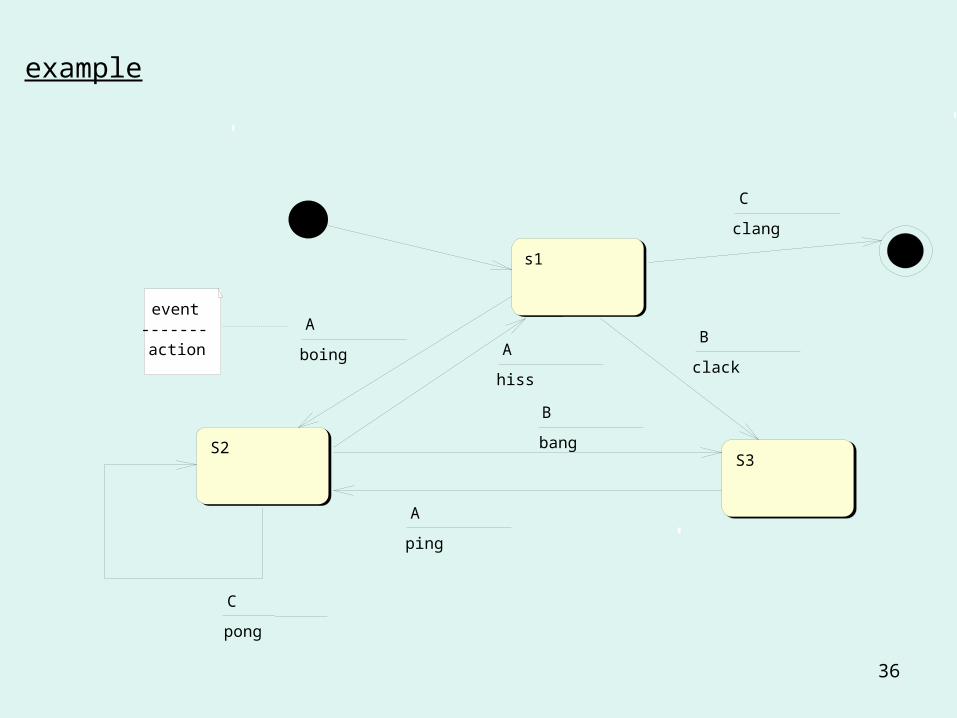
36
example
s1
S2S3
A
boingB
clack
B
bang
A
ping
C
clang
C
pong
event-------action A
hiss

37
Exercise
• 1.1. What sequence of noises does it make when the sequence ABACAC is in put?
• 1.2 What about BABAAC?• 1.3 What kind of error in the machine does the
sequence ACCBA reveal?• 1.4 What kind error in the machine does the
input BABC reveal?• 1.5 What kind of error does the sequence
ABAXAC reveal? • 1.6 Give other examples of good and bad input.