Embed Size (px)
Citation preview
GENERAL INFORMATION
Section Page
SCOPE AND USE OF THIS MANUAL ....................................................... 3
GENERAL DESCRIPTION ......................................................................... 3
ELECTRONIC ENGINE CONTROL SYSTEM ............................................ 4
ENGINE BRAKING POWER ....................................................................... 7
GENERAL SPECIFICATIONS AND ENGINE VIEWS ................................ 7
ENGINE MODEL AND SERIAL NUMBER ................................................. 13
E XHAUST G AS RE CIRCUL AT ION ( EG R) SY ST EM .................................. 14a
S AFE TY IN STRUCTIO NS A N D PRE CAUTIO NS ....................................... 15
E N G LIS H TO M ETR IC C ON VERS IO N ...................................................... 26
DE CIMA L A ND ME TR IC E QUIVA L ENT S ................................................... 27
TO RQUE S PE C IFICAT IO NS ...................................................................... 29
MBE 4000 SERVICE MANUAL
All information subject to change without notice.
2 From Bulletin 1-MBE4000-04 6SE412 0206 Copyright © 2004 DETROIT DIESEL CORPORATION
MBE 4000 SERVICE MANUAL
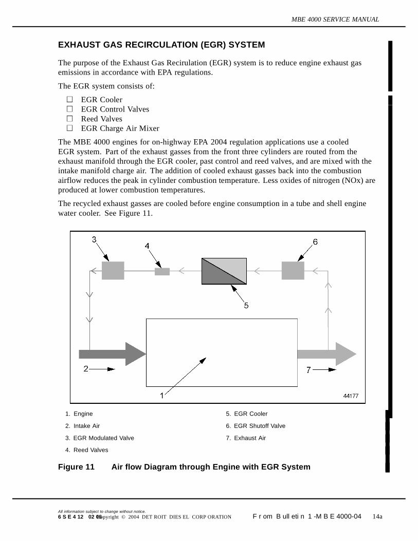
EXHAUST GAS RECIRCULATION (EGR) SYSTEM
The purpose of the Exhaust Gas Recirulation (EGR) system is to reduce engine exhaust gasemissions in accordance with EPA regulations.
The EGR system consists of:
EGR CoolerEGR Control ValvesReed ValvesEGR Charge Air Mixer
The MBE 4000 engines for on-highway EPA 2004 regulation applications use a cooledEGR system. Part of the exhaust gasses from the front three cylinders are routed from theexhaust manifold through the EGR cooler, past control and reed valves, and are mixed with theintake manifold charge air. The addition of cooled exhaust gasses back into the combustionairflow reduces the peak in cylinder combustion temperature. Less oxides of nitrogen (NOx) areproduced at lower combustion temperatures.
The recycled exhaust gasses are cooled before engine consumption in a tube and shell enginewater cooler. See Figure 11.
1. Engine 5. EGR Cooler
2. Intake Air 6. EGR Shutoff Valve
3. EGR Modulated Valve 7. Exhaust Air
4. Reed Valves
Figure 11 Air flow Diagram through Engine with EGR System
All information subject to change without notice.
6 S E 4 12 02 06 Copyright © 2004 DET ROIT DIES EL CORP ORATION F r om B ull eti n 1 -M B E 4000-04 14a
MBE 4000 SERVICE MANUAL
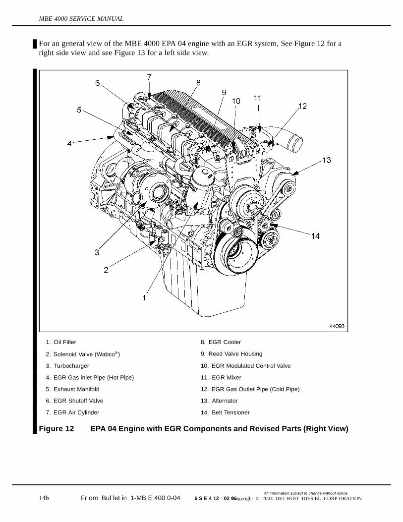
For an general view of the MBE 4000 EPA 04 engine with an EGR system, See Figure 12 for aright side view and see Figure 13 for a left side view.
1. Oil Filter 8. EGR Cooler
2. Solenoid Valve (Wabco®) 9. Reed Valve Housing
3. Turbocharger 10. EGR Modulated Control Valve
4. EGR Gas inlet Pipe (Hot Pipe) 11. EGR Mixer
5. Exhaust Manifold 12. EGR Gas Outlet Pipe (Cold Pipe)
6. EGR Shutoff Valve 13. Alternator
7. EGR Air Cylinder 14. Belt Tensioner
Figure 12 EPA 04 Engine with EGR Components and Revised Parts (Right View)
All information subject to change without notice.
14b Fr om Bul let in 1-MB E 400 0-04 6 S E 4 12 02 06 Copyright © 2004 DET ROIT DIES EL CORP ORATION
MBE 4000 SERVICE MANUAL
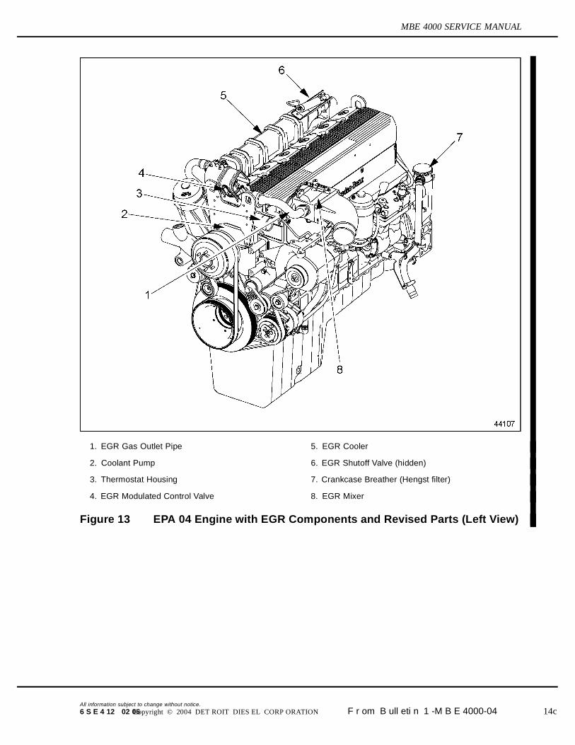
1. EGR Gas Outlet Pipe 5. EGR Cooler
2. Coolant Pump 6. EGR Shutoff Valve (hidden)
3. Thermostat Housing 7. Crankcase Breather (Hengst filter)
4. EGR Modulated Control Valve 8. EGR Mixer
Figure 13 EPA 04 Engine with EGR Components and Revised Parts (Left View)
All information subject to change without notice.
6 S E 4 12 02 06 Copyright © 2004 DET ROIT DIES EL CORP ORATION F r om B ull eti n 1 -M B E 4000-04 14c
MBE 4000 SERVICE MANUAL
EGR Cooler
The EGR Cooler is equipped with a single-pass cooler. Part of the exhaust gasses from the firstthree cylinders are directed through the EGR shutoff valve and through the cooler and reed valves,past the EGR modulated control valve and the mixer and then back to the cylinder.
EGR Control Valves
There are two EGR valves on the MBE 4000 EGR engine — the EGR shutoff valve and the EGRmodulated control valve. The EGR shutoff valve is a pneumatically driven butterfly valve,located at the inlet of the EGR cooler. It closes when the exhaust flap or turbo-brake actuates,avoiding exhaust gas flow and excessive pressure in the EGR cooler and reed valves. The EGRmodulated control valve is an electronically actuated butterfly valve located after the EGR coolerand reed valves, controlled by the DDEC-ECU (formerly PLD-MR). This valve controls theexhaust gas flow for the intake manifold.
Reed Valves
The reed valves work like a check valve, allowing flow of gas only in one direction, avoiding gasback flow when the intake pressure is higher than exhaust gas pressure. As the average exhaustpressure is lower than the intake pressure, the gas flow through the reed valves is possible due toexhaust gas pressure peaks — peaks slightly higher than the intake air pressure, which occur asthe engine exhaust valves open. During this peak of pressure, the reed valves open and allow gasflow to the EGR modulated valve and mixer.
EGR Mixer
The purpose of the mixer is to ensure good mixing of the cooled EGR gasses with filtered chargeair. Once the exhaust gasses are cooled and have completed their cycle through the EGR system,they are released into the EGR mixer. The recycled exhaust gasses are combined with the chargedair and directed to the cylinders.
All information subject to change without notice.
14d Fr om Bul let in 1-MB E 400 0-04 6 S E 4 12 02 06 Copyright © 2004 DET ROIT DIES EL CORP ORATION