Embed Size (px)
Citation preview
1
11 Dec 2007 Dr. S. NallayarasuDepartment of Ocean Engineering
Indian Institute of Technology Madras-36
1
Offshore Structures – Loads
Classification of water waves, Formulation of potential flow equation, Small amplitude wave theory, Finite amplitude waves (Stokian, Solitary and Cnoidal wave theories), Regular and random waves, Wave current interactions;
Ocean wave statistics, short term and long term wave height distribution, power-spectral definition of ocean waves, PM Spectra, Jonswap Spectra, and ISSC Spectra, extreme wave prediction, determination of design wave heights and periods, fatigue wave heights, Joint probability distribution of waves heights and periods;
Wave and Current Loads, Morison equation, Wind Loads; Gravity Loads, and combinations; Drilling Rig Loads; Design wave method, Spectral energy method, Wave Directions; Loads based on maximum base shear, Loads based on maximum over turning moment, Selection of drag and inertia coefficients marine growth, API RP 2A recommendations, Diffraction, Load on large diameter cylinders, Wave-Structure interaction;
11 Dec 2007 Dr. S. NallayarasuDepartment of Ocean Engineering
Indian Institute of Technology Madras-36
2
Offshore Structures – Loads
ContentsGravity LoadsWind LoadsWave and Current Loads – Small bodiesWave and Current Loads – Large Bodies
2
11 Dec 2007 Dr. S. NallayarasuDepartment of Ocean Engineering
Indian Institute of Technology Madras-36
3
Offshore Structures – Loads
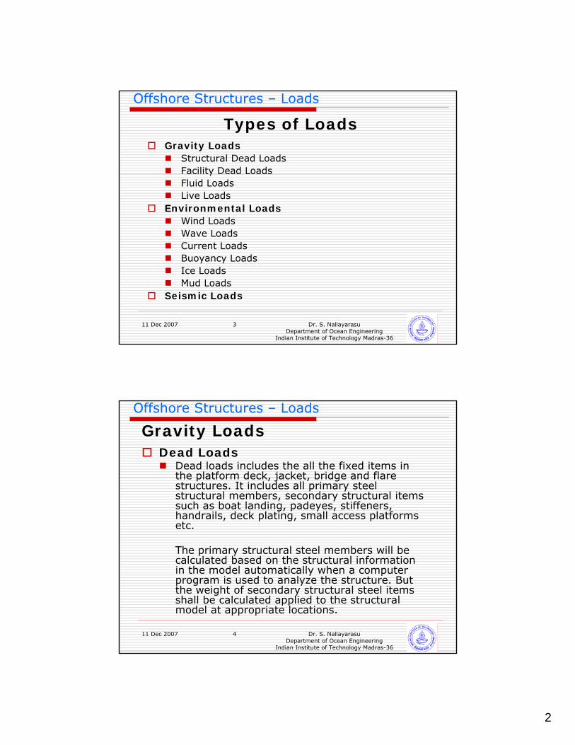
Types of LoadsGravity Loads
Structural Dead LoadsFacility Dead LoadsFluid LoadsLive Loads
Environmental LoadsWind LoadsWave LoadsCurrent LoadsBuoyancy LoadsIce LoadsMud Loads
Seismic Loads
11 Dec 2007 Dr. S. NallayarasuDepartment of Ocean Engineering
Indian Institute of Technology Madras-36
4
Offshore Structures – Loads
Gravity LoadsDead Loads
Dead loads includes the all the fixed items in the platform deck, jacket, bridge and flare structures. It includes all primary steel structural members, secondary structural items such as boat landing, padeyes, stiffeners, handrails, deck plating, small access platforms etc.
The primary structural steel members will be calculated based on the structural information in the model automatically when a computer program is used to analyze the structure. But the weight of secondary structural steel items shall be calculated applied to the structural model at appropriate locations.

3
11 Dec 2007 Dr. S. NallayarasuDepartment of Ocean Engineering
Indian Institute of Technology Madras-36
5
Offshore Structures – Loads
Facility LoadsThe structure built either for drilling or wellhead type platform or for process type platform supports various equipment and facilities.
Mechanical equipmentElectrical equipmentPiping connecting each equipmentElectrical Cable traysInstrumentation items
11 Dec 2007 Dr. S. NallayarasuDepartment of Ocean Engineering
Indian Institute of Technology Madras-36
6
Offshore Structures – Loads
Dead loadsMovable Drill floor loadsDrill string weight
Depending on the type of drilling rig used, this loads will vary. For water depth less than 70m, Jackup type rig may be used. For deeper water depths, operation of Jackup type rigs become uneconomical and deck mounted drilling rigs will be a suitable option. Weight of such rig will be around 1500 Tonnes with an additional support module of 1000 Tonnes.
Drilling Loads include reaction from Jackupcantilever type rig or Deck mounted rigs.
Drilling Loads
4
11 Dec 2007 Dr. S. NallayarasuDepartment of Ocean Engineering
Indian Institute of Technology Madras-36
7
Offshore Structures – Loads
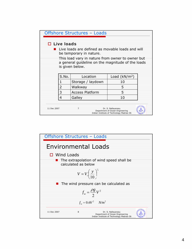
Live loadsLive loads are defined as movable loads and will be temporary in nature. This load vary in nature from owner to owner but a general guideline on the magnitude of the loads is given below.
10Galley4
5Access Platform3
5Walkway2
10Storage / laydown1
Load (kN/m2)LocationS.No.
11 Dec 2007 Dr. S. NallayarasuDepartment of Ocean Engineering
Indian Institute of Technology Madras-36
8
Offshore Structures – Loads
Environmental LoadsWind Loads
The extrapolation of wind speed shall be calculated as below
81
0 10 ⎟⎠⎞
⎜⎝⎛=
yVV
The wind pressure can be calculated as
2
2Vgfw
ρ=
22 6.0 N/mVfw =
5
11 Dec 2007 Dr. S. NallayarasuDepartment of Ocean Engineering
Indian Institute of Technology Madras-36
9
Offshore Structures – Loads
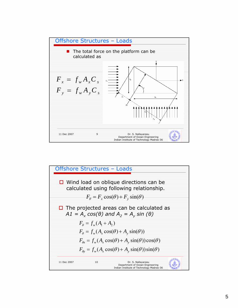
The total force on the platform can be calculated as
sywy
sxwx
CAfFCAfF
==
11 Dec 2007 Dr. S. NallayarasuDepartment of Ocean Engineering
Indian Institute of Technology Madras-36
10
Offshore Structures – Loads
Wind load on oblique directions can be calculated using following relationship.
)sin()cos( θθθ yx FFF +=
The projected areas can be calculated as A1 = Ax cos(θ) and A2 = Ay sin (θ)
)sin())sin()cos((
)cos())sin()cos((
))sin()cos(()( 21
θθθ
θθθ
θθ
θ
θ
θ
θ
yxwy
yxwx
yxw
w
AAfF
AAfF
AAfFAAfF
+=
+=
+=+=
6
11 Dec 2007 Dr. S. NallayarasuDepartment of Ocean Engineering
Indian Institute of Technology Madras-36
11
Offshore Structures – Loads
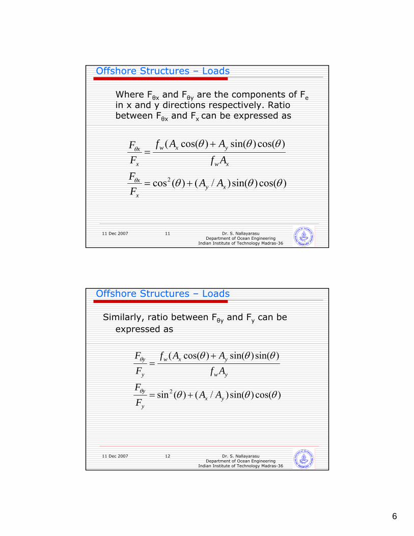
Where Fθx and Fθy are the components of Fein x and y directions respectively. Ratio between Fθx and Fx can be expressed as
)cos()sin()/()(cos
)cos()sin()cos((
2 θθθ
θθθ
θ
θ
xyx
x
xw
yxw
x
x
AAFF
AfAAf
FF
+=
+=
11 Dec 2007 Dr. S. NallayarasuDepartment of Ocean Engineering
Indian Institute of Technology Madras-36
12
Offshore Structures – Loads
Similarly, ratio between Fθy and Fy can be expressed as
)cos()sin()/()(sin
)sin()sin()cos((
2 θθθ
θθθ
θ
θ
yxy
y
yw
yxw
y
y
AAFF
AfAAf
FF
+=
+=
7
11 Dec 2007 Dr. S. NallayarasuDepartment of Ocean Engineering
Indian Institute of Technology Madras-36
13
Offshore Structures – Loads
WAVE FORCES ON SMALL BODIES
11 Dec 2007 Dr. S. NallayarasuDepartment of Ocean Engineering
Indian Institute of Technology Madras-36
14
Offshore Structures – Loads
Wave and Current LoadsMethodology
In applying design waves load on to the offshore structures, there are two ways of applying itDesign Wave methodSpectral Method
In design wave method, a discrete set of design waves (maximum) and associated periods will be selected to generate loads on the structure. These loads will be used to compute the response of the structure.
In the spectral method, a energy spectrum of the sea-state for the location will be taken and a transfer function for the response will be generated. These transfer function will be used to compute the stresses in the structural members
8
11 Dec 2007 Dr. S. NallayarasuDepartment of Ocean Engineering
Indian Institute of Technology Madras-36
15
Offshore Structures – Loads
Design Wave MethodThe forces exerted by waves are most dominant in
governing the jacket structures design especially the foundation piles. The wave loads exerted on the jacket is applied laterally on all members and it generates overturning moment on the structure.
Period of wind generated waves in the open sea can be in the order of 2 to 20 seconds. These waves are called gravity waves and contain most part of wave energy.
Maximum wave shall be used for the design of offshore structures. The relationship between the significant wave height (Hs) and the maximum wave height (Hmax) is
Hmax= 1.86 HsThe above equation correspond to a computation based
on 1000 waves in a record.
11 Dec 2007 Dr. S. NallayarasuDepartment of Ocean Engineering
Indian Institute of Technology Madras-36
16
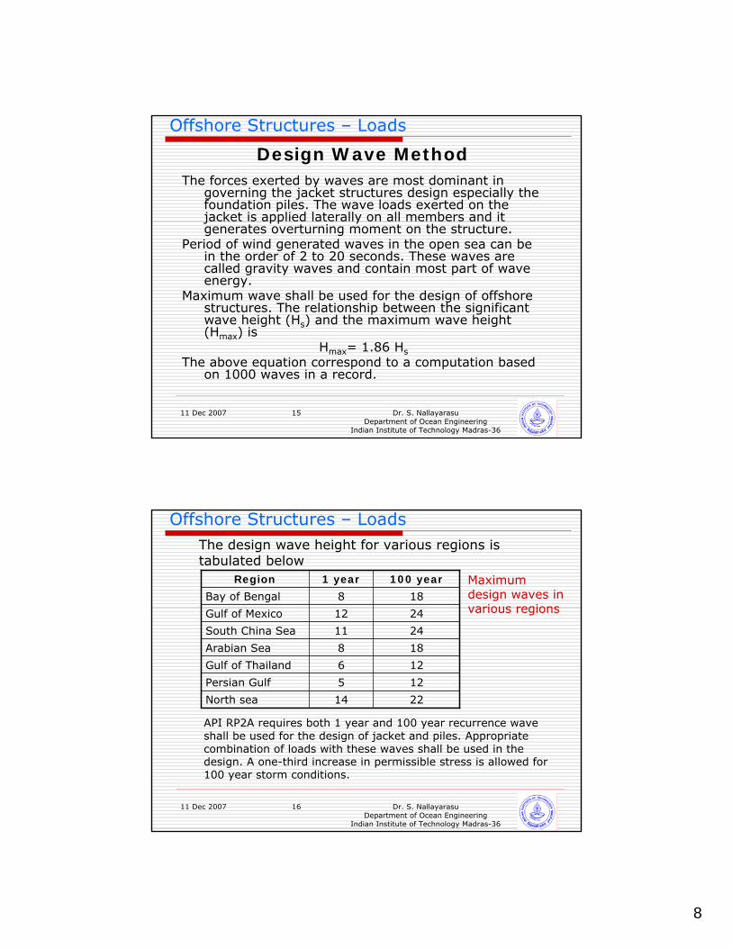
Offshore Structures – LoadsThe design wave height for various regions is tabulated below
2214North sea
125Persian Gulf
126Gulf of Thailand
188Arabian Sea
2411South China Sea
12
8
1 year
24Gulf of Mexico
18Bay of Bengal
100 yearRegion
API RP2A requires both 1 year and 100 year recurrence wave shall be used for the design of jacket and piles. Appropriate combination of loads with these waves shall be used in the design. A one-third increase in permissible stress is allowed for 100 year storm conditions.
Maximum design waves in various regions
9
11 Dec 2007 Dr. S. NallayarasuDepartment of Ocean Engineering
Indian Institute of Technology Madras-36
17
Offshore Structures – Loads
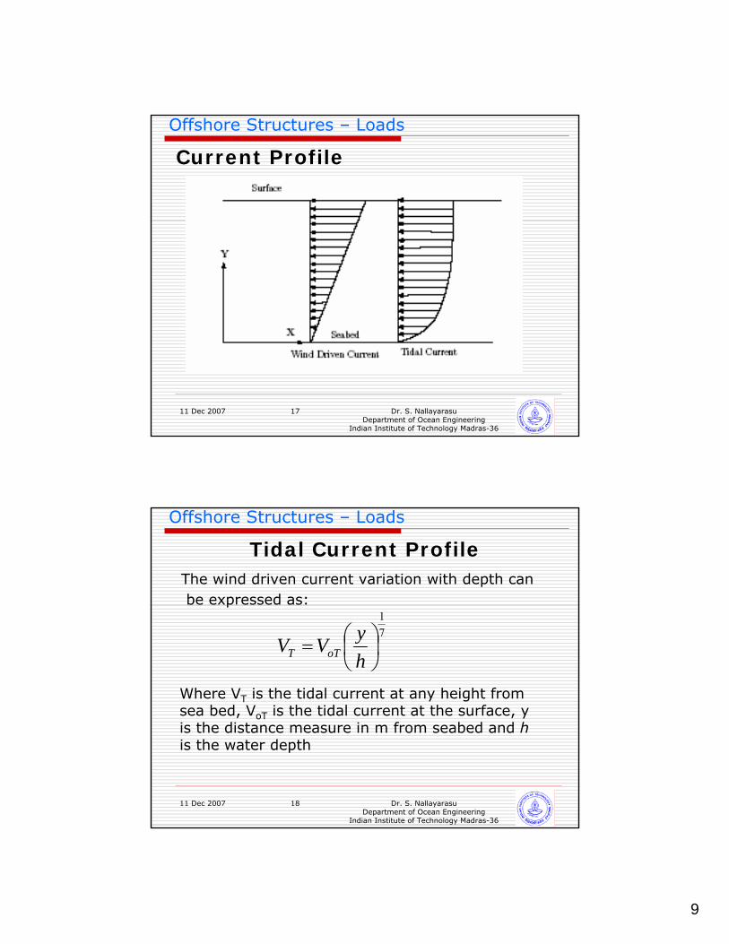
Current Profile
11 Dec 2007 Dr. S. NallayarasuDepartment of Ocean Engineering
Indian Institute of Technology Madras-36
18
Offshore Structures – Loads
Tidal Current ProfileThe wind driven current variation with depth canbe expressed as:
Where VT is the tidal current at any height from sea bed, VoT is the tidal current at the surface, y is the distance measure in m from seabed and his the water depth
71
⎟⎠⎞
⎜⎝⎛=
hyVV oTT
10
11 Dec 2007 Dr. S. NallayarasuDepartment of Ocean Engineering
Indian Institute of Technology Madras-36
19
Offshore Structures – Loads
Wind Driven Current ProfileThe current variation with depth can be expressed as:
Where VW is the wind driven current at any height from sea bed, VoW is the wind driven current at the surface, y is the distance measure in m from seabed and h is the water depth
hyVV oWW =
11 Dec 2007 Dr. S. NallayarasuDepartment of Ocean Engineering
Indian Institute of Technology Madras-36
20
Offshore Structures – Loads
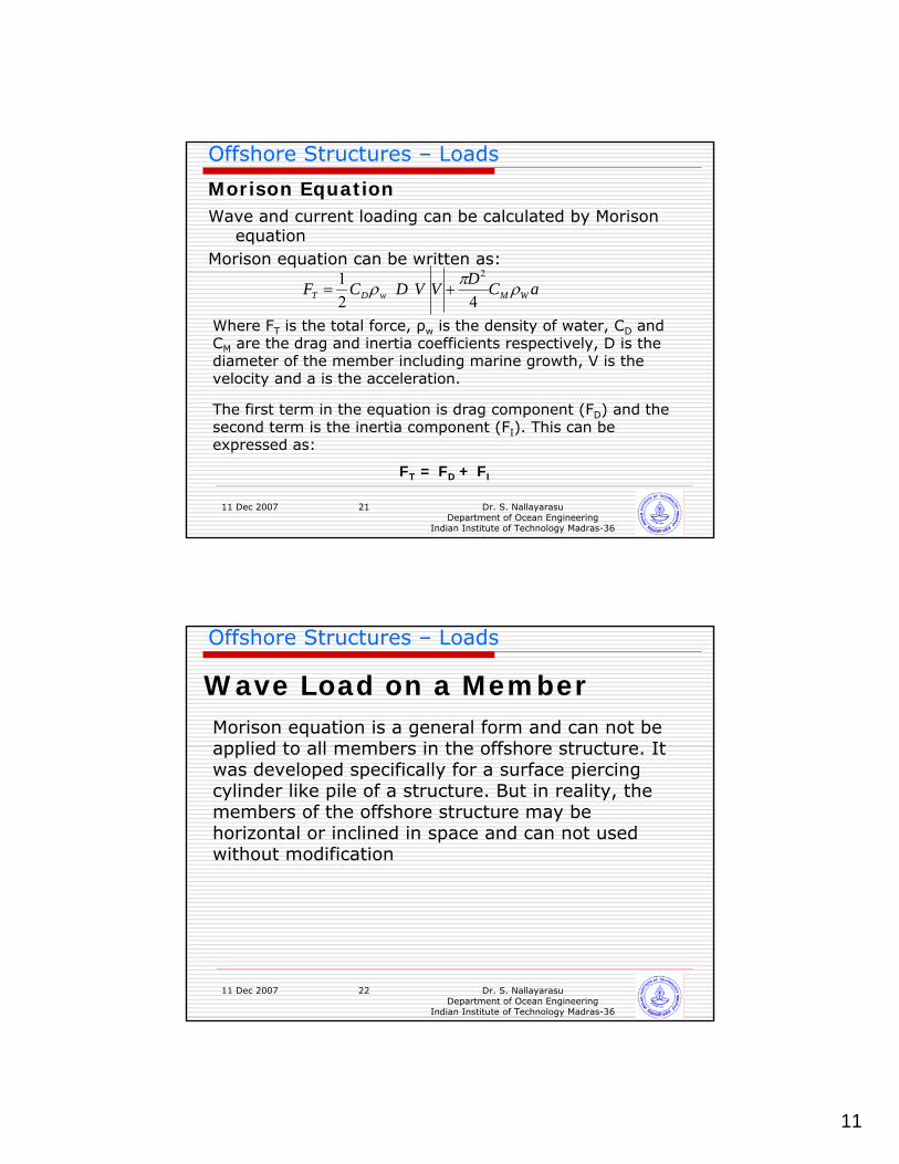
Morison Equation
Flow is assumed to be not disturbed by the presence of the structureForce calculation is empirical calibrated by experimental resultsSuitable Coefficients need to be used depending on the shape of the bodyValidity range shall be checked before use and generally suitable for most jacket type structures where D/L << 0.2 where D is the diameter of the structural member and L is the wave length
11
11 Dec 2007 Dr. S. NallayarasuDepartment of Ocean Engineering
Indian Institute of Technology Madras-36
21
Offshore Structures – Loads
Morison EquationWave and current loading can be calculated by Morison
equationMorison equation can be written as:
aCDVVDCF WMwDT ρπρ4
21 2
+=
Where FT is the total force, ρw is the density of water, CD and CM are the drag and inertia coefficients respectively, D is the diameter of the member including marine growth, V is the velocity and a is the acceleration.
The first term in the equation is drag component (FD) and the second term is the inertia component (FI). This can be expressed as:
FT = FD + FI
11 Dec 2007 Dr. S. NallayarasuDepartment of Ocean Engineering
Indian Institute of Technology Madras-36
22
Offshore Structures – Loads
Wave Load on a MemberMorison equation is a general form and can not be applied to all members in the offshore structure. It was developed specifically for a surface piercing cylinder like pile of a structure. But in reality, the members of the offshore structure may be horizontal or inclined in space and can not used without modification
12
11 Dec 2007 Dr. S. NallayarasuDepartment of Ocean Engineering
Indian Institute of Technology Madras-36
23
Offshore Structures – Loads
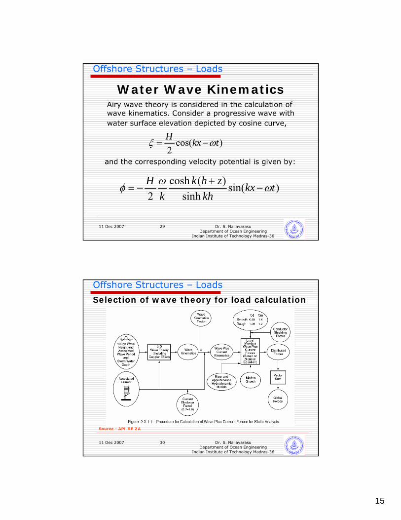
STEPSEstablish Wave Height, Period and Current Distribution along the depthEstablish Wave Theory applicable for H,T,dEstimation of Water particle kinematics including wave current interactionEstablish Cd and CmEstablish Marine GrowthEstablish Wave Kinematics factorConductor Shielding (if applicable)Current Blockage factorMorison Equation used to estimate the forces
11 Dec 2007 Dr. S. NallayarasuDepartment of Ocean Engineering
Indian Institute of Technology Madras-36
24
Offshore Structures – Loads
WAVE CURRENT INTERACTIONPresence of current either stretches the wave or shortens it depending on the direction of current. This is called Doppler shift. The apparent wave period need to be calculated to use in the load calculationDrag term is nonlinear and hence the water particle velocities due to wave and current needs to be added vectorialy before using it in Morison equation.
13
11 Dec 2007 Dr. S. NallayarasuDepartment of Ocean Engineering
Indian Institute of Technology Madras-36
25
Offshore Structures – Loads
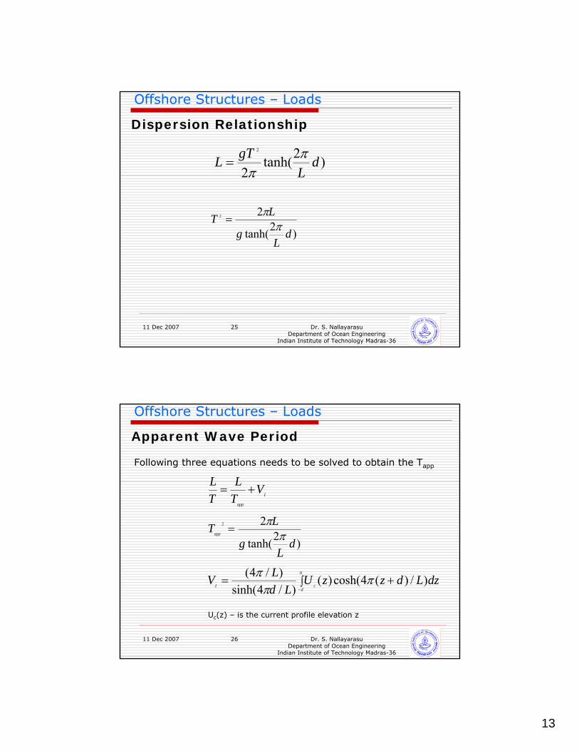
Dispersion Relationship
)2tanh(2
2
dL
gTL ππ
=
)2tanh(
22
dL
g
LTπ
π=
11 Dec 2007 Dr. S. NallayarasuDepartment of Ocean Engineering
Indian Institute of Technology Madras-36
26
Offshore Structures – Loads
Apparent Wave Period
I
app
VTL
TL
+=
∫−
+=0
)/)(4cosh()()/4sinh(
)/4(d
cIdzLdzzU
LdLV π
ππ
)2tanh(
22
dL
g
LTapp π
π=
Uc(z) – is the current profile elevation z
Following three equations needs to be solved to obtain the Tapp
14
11 Dec 2007 Dr. S. NallayarasuDepartment of Ocean Engineering
Indian Institute of Technology Madras-36
27
Offshore Structures – Loads
Nonlinear Drag Term in Morison equation
VwVcV
aCDVVDCFWMwDT
+=
+= ρπρ4
21 2
Vc = Current Velocity
Vw = Wave Water Particle Velocity
Example
Lets assume Vc=2m/sec, Vw=3m/sec
If we calculate the drag forces separately, add, we will get 2*2+ 3*3 = 13
If we add the velocities first and compute the loads, we get (2+3)*(2+3) = 25
It under predicts the forces as much as by 50%
11 Dec 2007 Dr. S. NallayarasuDepartment of Ocean Engineering
Indian Institute of Technology Madras-36
28
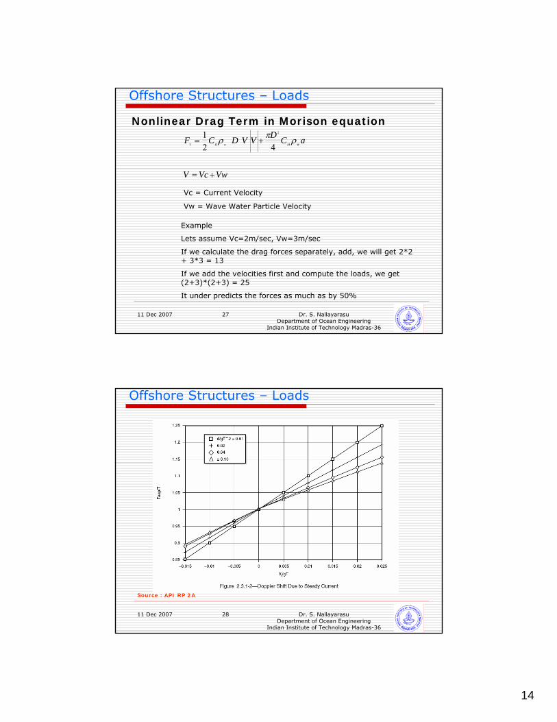
Offshore Structures – Loads
Source : API RP 2A
15
11 Dec 2007 Dr. S. NallayarasuDepartment of Ocean Engineering
Indian Institute of Technology Madras-36
29
Offshore Structures – Loads
Water Wave KinematicsAiry wave theory is considered in the calculation of wave kinematics. Consider a progressive wave with water surface elevation depicted by cosine curve,
)cos(2
tkxH ωξ −=
and the corresponding velocity potential is given by:
)sin(sinh
)(cosh2
tkxkh
zhkk
H ωωφ −+
−=
11 Dec 2007 Dr. S. NallayarasuDepartment of Ocean Engineering
Indian Institute of Technology Madras-36
30
Offshore Structures – Loads
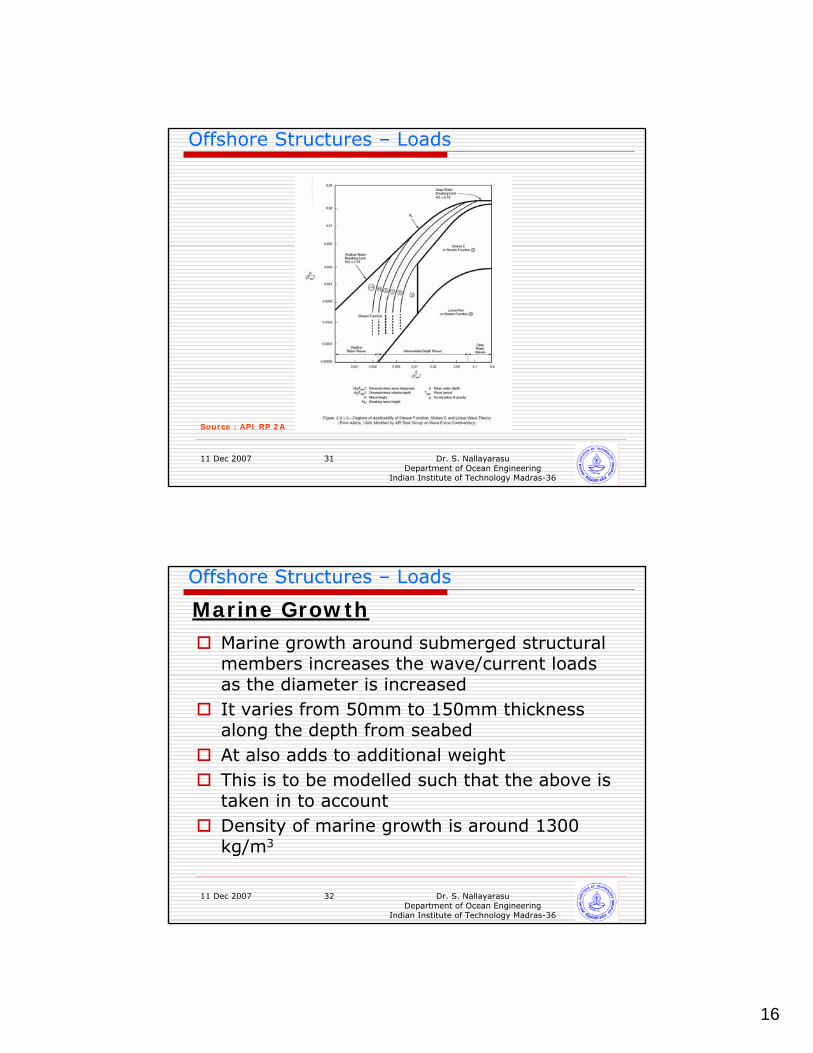
Selection of wave theory for load calculation
Source : API RP 2A
16
11 Dec 2007 Dr. S. NallayarasuDepartment of Ocean Engineering
Indian Institute of Technology Madras-36
31
Offshore Structures – Loads
Source : API RP 2A
11 Dec 2007 Dr. S. NallayarasuDepartment of Ocean Engineering
Indian Institute of Technology Madras-36
32
Offshore Structures – Loads
Marine GrowthMarine growth around submerged structural members increases the wave/current loads as the diameter is increasedIt varies from 50mm to 150mm thickness along the depth from seabedAt also adds to additional weightThis is to be modelled such that the above is taken in to accountDensity of marine growth is around 1300 kg/m3
17
11 Dec 2007 Dr. S. NallayarasuDepartment of Ocean Engineering
Indian Institute of Technology Madras-36
33
Offshore Structures – Loads
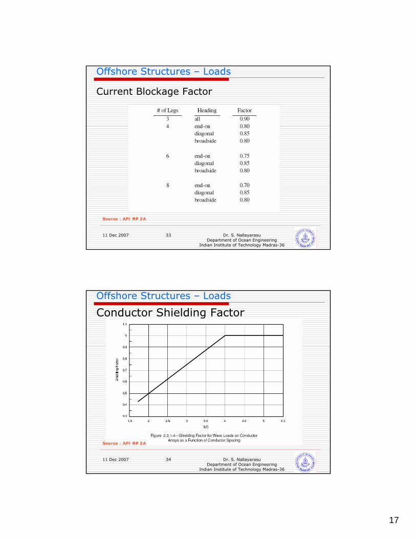
Current Blockage Factor
Source : API RP 2A
11 Dec 2007 Dr. S. NallayarasuDepartment of Ocean Engineering
Indian Institute of Technology Madras-36
34
Offshore Structures – Loads
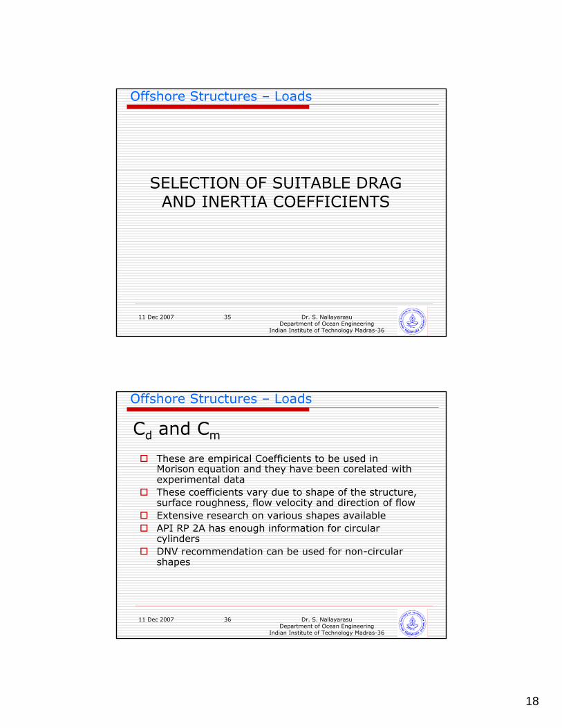
Conductor Shielding Factor
Source : API RP 2A
18
11 Dec 2007 Dr. S. NallayarasuDepartment of Ocean Engineering
Indian Institute of Technology Madras-36
35
Offshore Structures – Loads
SELECTION OF SUITABLE DRAG AND INERTIA COEFFICIENTS
11 Dec 2007 Dr. S. NallayarasuDepartment of Ocean Engineering
Indian Institute of Technology Madras-36
36
Offshore Structures – Loads
Cd and Cm
These are empirical Coefficients to be used in Morison equation and they have been corelated with experimental dataThese coefficients vary due to shape of the structure, surface roughness, flow velocity and direction of flowExtensive research on various shapes availableAPI RP 2A has enough information for circular cylindersDNV recommendation can be used for non-circular shapes
19
11 Dec 2007 Dr. S. NallayarasuDepartment of Ocean Engineering
Indian Institute of Technology Madras-36
37
Offshore Structures – Loads
Cd and Cm
For Smooth cylinders Cd = 0.65, Cm=1.6For rough cylinders Cd = 1.05, cm=1.2
The values shall be used only if UT/D > 30For other region of flow, charts available literature shall be used
11 Dec 2007 Dr. S. NallayarasuDepartment of Ocean Engineering
Indian Institute of Technology Madras-36
38
Offshore Structures – Loads
Keulegan-Carpenter Number
DTUK m 22
=
Where K is Keulegan-Carpenter Number, Um is the maximum velocity including current and T2 is the duration of half wave cycle and D is the diameter of the member
20
11 Dec 2007 Dr. S. NallayarasuDepartment of Ocean Engineering
Indian Institute of Technology Madras-36
39
Offshore Structures – Loads
Reynold’s Number
νDUR m=
Where R is Reynold’s Number, Um is the maximum velocity including current and D is the diameter of the memberν is the kinematic viscosity
11 Dec 2007 Dr. S. NallayarasuDepartment of Ocean Engineering
Indian Institute of Technology Madras-36
40
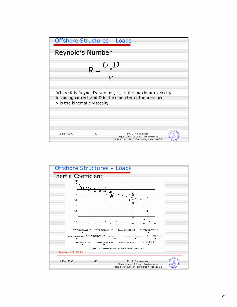
Offshore Structures – LoadsInertia Coefficient
Source : API RP 2A
21
11 Dec 2007 Dr. S. NallayarasuDepartment of Ocean Engineering
Indian Institute of Technology Madras-36
41
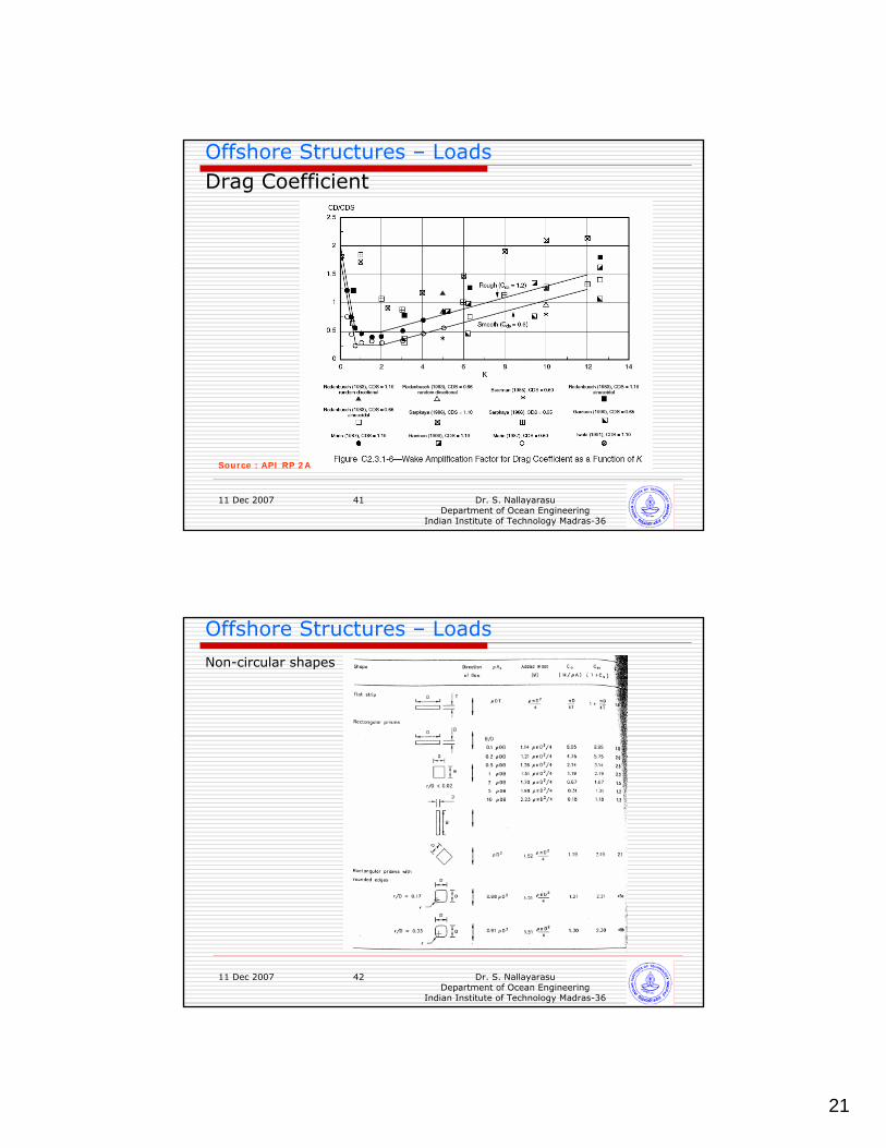
Offshore Structures – LoadsDrag Coefficient
Source : API RP 2A
11 Dec 2007 Dr. S. NallayarasuDepartment of Ocean Engineering
Indian Institute of Technology Madras-36
42
Offshore Structures – Loads
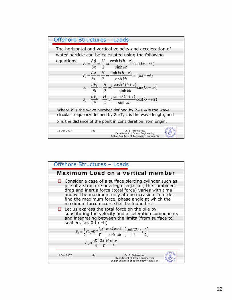
Non-circular shapes
22
11 Dec 2007 Dr. S. NallayarasuDepartment of Ocean Engineering
Indian Institute of Technology Madras-36
43
Offshore Structures – Loads
The horizontal and vertical velocity and acceleration of water particle can be calculated using the following equations.
)cos(sinh
)(sinh2
)sin(sinh
)(cosh2
)sin(sinh
)(sinh2
)cos(sinh
)(cosh2
2
2
tkxkh
zhkHt
Va
tkxkh
zhkHt
Va
tkxkh
zhkHz
V
tkxkh
zhkHx
V
vv
hh
v
h
ωω
ωω
ωωφ
ωωφ
−+
=∂∂
=
−+
=∂∂
=
−+
=∂∂
=
−+
=∂∂
=
Where k is the wave number defined by 2π/T, ω is the wave circular frequency defined by 2π/T, L is the wave length, and
x is the distance of the point in consideration from origin.
11 Dec 2007 Dr. S. NallayarasuDepartment of Ocean Engineering
Indian Institute of Technology Madras-36
44
Offshore Structures – Loads
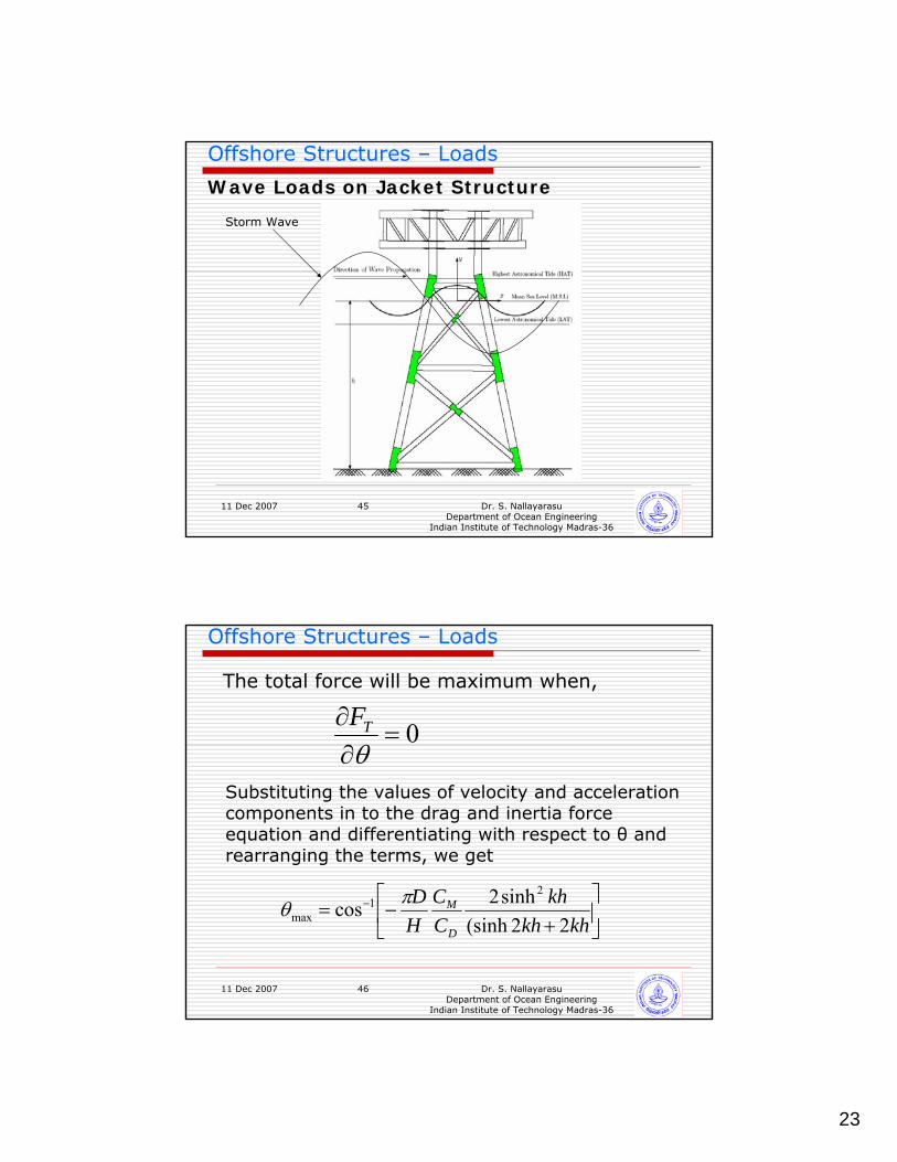
Maximum Load on a vertical memberConsider a case of a surface piercing cylinder such as pile of a structure or a leg of a jacket, the combined drag and inertia force (total force) varies with time and will be maximum only at one occasion. In order find the maximum force, phase angle at which the maximum force occurs shall be found first.Let us express the total force on the pile by substituting the velocity and acceleration components and integrating between the limits (from surface to seabed, i.e. 0 to –h)
kTHD
hk
khkhT
HDCF DT
θππρ
θθπρ
sin24
C-
24)2sinh(
sinhcoscos
21
2
22
M
22
22
⎥⎦⎤
⎢⎣⎡ +=
23
11 Dec 2007 Dr. S. NallayarasuDepartment of Ocean Engineering
Indian Institute of Technology Madras-36
45
Offshore Structures – Loads
Wave Loads on Jacket Structure
Storm Wave
11 Dec 2007 Dr. S. NallayarasuDepartment of Ocean Engineering
Indian Institute of Technology Madras-36
46
Offshore Structures – Loads
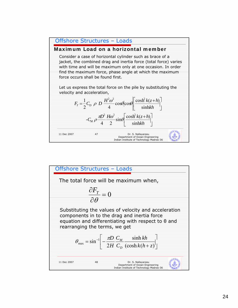
The total force will be maximum when,
0=∂∂θ
TF
Substituting the values of velocity and acceleration components in to the drag and inertia force equation and differentiating with respect to θ and rearranging the terms, we get
⎥⎦
⎤⎢⎣
⎡+
−= −
khkhkh
CC
HD
D
M
22(sinhsinh2cos
21
maxπθ
24
11 Dec 2007 Dr. S. NallayarasuDepartment of Ocean Engineering
Indian Institute of Technology Madras-36
47
Offshore Structures – Loads
Maximum Load on a horizontal memberConsider a case of horizontal cylinder such as brace of a jacket, the combined drag and inertia force (total force) varieswith time and will be maximum only at one occasion. In order find the maximum force, phase angle at which the maximum force occurs shall be found first.
Let us express the total force on the pile by substituting the velocity and acceleration,
⎥⎦
⎤⎢⎣
⎡ +
⎥⎦
⎤⎢⎣
⎡ +=
khhzkHD-C
khhzkHDCF
M
DT
sinh)(coshsin
24
sinh)(coshcoscos
4
21
222
222
θωπρ
θθωρ
11 Dec 2007 Dr. S. NallayarasuDepartment of Ocean Engineering
Indian Institute of Technology Madras-36
48
Offshore Structures – Loads
The total force will be maximum when,
0=∂∂θ
TF
Substituting the values of velocity and acceleration components in to the drag and inertia force equation and differentiating with respect to θ and rearranging the terms, we get
⎥⎦
⎤⎢⎣
⎡+
−= −
)((coshsinh
2sin 1
max zhkkh
CC
HD
D
Mπθ
25
11 Dec 2007 Dr. S. NallayarasuDepartment of Ocean Engineering
Indian Institute of Technology Madras-36
49
Offshore Structures – Loads
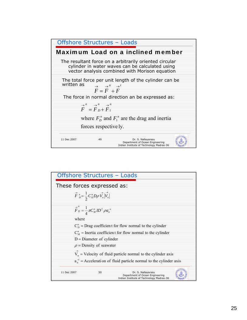
Maximum Load on a inclined memberThe resultant force on a arbitrarily oriented circular
cylinder in water waves can be calculated using vector analysis combined with Morison equation
tn
FFF→→→
+=The force in normal direction an be expressed as:
ly.respective forces inertia and drag theare and where 1
1
nnD
nn
D
n
FFFFF→→→
+=
The total force per unit length of the cylinder can be written as
11 Dec 2007 Dr. S. NallayarasuDepartment of Ocean Engineering
Indian Institute of Technology Madras-36
50
Offshore Structures – Loads
These forces expressed as:
axiscylinder the tonormal particle fluid ofon Accelerati a
axiscylinder the tonormal particle fluid ofVelocity V
seawater ofDensity cylinder ofDiameter D
cylinder the tonormal flowfor t coefficien Inertia C
cylinder the tonormal flowfor t coefficien Drag Cwhere
41
21
n
n
nM
nD
2
=
=
===
=
=
=
→
→
→→
→→→
ρ
ρπ
ρ
nnM
n
D
nnnD
nD
aIDCF
VVDCF
26
11 Dec 2007 Dr. S. NallayarasuDepartment of Ocean Engineering
Indian Institute of Technology Madras-36
51
Offshore Structures – Loads
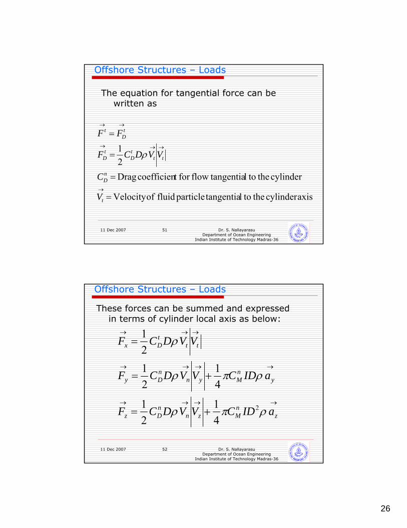
The equation for tangential force can be written as
axiscylinder the tol tangentiaparticle fluid ofVelocity
cylinder the tol tangentiaflowfor t coefficien Drag 21
=
=
=
=
→
→→→
→→
t
nD
tttD
tD
tD
t
V
C
VVDCF
FF
ρ
11 Dec 2007 Dr. S. NallayarasuDepartment of Ocean Engineering
Indian Institute of Technology Madras-36
52
Offshore Structures – Loads
These forces can be summed and expressed in terms of cylinder local axis as below:
→→→→
→→→→
→→→
+=
+=
=
znMzn
nDz
ynMyn
nDy
tttDx
aIDCVVDCF
aIDCVVDCF
VVDCF
ρπρ
ρπρ
ρ
2
41
21
41
2121
27
11 Dec 2007 Dr. S. NallayarasuDepartment of Ocean Engineering
Indian Institute of Technology Madras-36
53
Offshore Structures – Loads
Maximum Global Loads
Maximum global loads on a platform can be calculated using two principles
Maximum Base Shear MethodMaximum Overturning Moment Method
11 Dec 2007 Dr. S. NallayarasuDepartment of Ocean Engineering
Indian Institute of Technology Madras-36
54
Offshore Structures – Loads
Maximum Base ShearMaximum base shear or maximum total force on a structure has to be determined for the global analysis of structures. As the wave propagates across structure wave force on each member is different and all the locations will not be attaining the maximum forces. To find the maximum total force a structure, following steps need to be considered.
Position the wave crest at the origin of the structure as shown in figure. Divide one wave cycle into number of segments either in terms of θ or in terms of lengthCompute the wave forces on all members at that instant of time using water wave velocities and accelerations computedSum up the forces in horizontal direction for all the membersRepeat the calculation in step 4 for all the points for one wavecycleThe maximum of all the total forces computed in step 5 is the maximum base shear or total force.
28
11 Dec 2007 Dr. S. NallayarasuDepartment of Ocean Engineering
Indian Institute of Technology Madras-36
55
Offshore Structures – Loads
Maximum Overturning Moment
Maximum overturning moment on a structure can be determined following the procedure for the maximum bas shear case. In this case, the loads on the members shall be multiplied by the lever arm from mud-line. This shall be summed up and the procedure shall be repeated for all the steps in the wave.
11 Dec 2007 Dr. S. NallayarasuDepartment of Ocean Engineering
Indian Institute of Technology Madras-36
56
Offshore Structures – Loads
Hydrodynamic Factors
Wave Kinematics factor This varies between 0.8 to 0.95. This is to be applied since the calculated wave loading is based two dimensional wave theory while the actual loading is from three dimensional wave climate.
Conductor Shielding factorThe presence of rows of conductors will provide a shielding effect to the conductors behind and this depends on the spacing and number of conductors
Current Blockage FactorThis current blockage factor is used to account for the reduction in the current due to the presence of the structure in a free stream.
29
11 Dec 2007 Dr. S. NallayarasuDepartment of Ocean Engineering
Indian Institute of Technology Madras-36
57
Offshore Structures – Loads
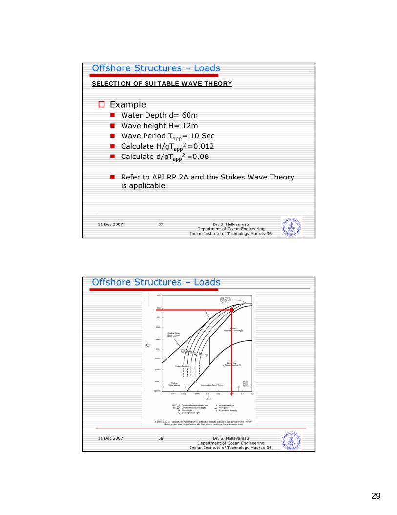
SELECTION OF SUITABLE WAVE THEORY
ExampleWater Depth d= 60mWave height H= 12mWave Period Tapp= 10 SecCalculate H/gTapp
2 =0.012Calculate d/gTapp
2 =0.06
Refer to API RP 2A and the Stokes Wave Theory is applicable
11 Dec 2007 Dr. S. NallayarasuDepartment of Ocean Engineering
Indian Institute of Technology Madras-36
58
Offshore Structures – Loads
30
11 Dec 2007 Dr. S. NallayarasuDepartment of Ocean Engineering
Indian Institute of Technology Madras-36
59
Offshore Structures – Loads
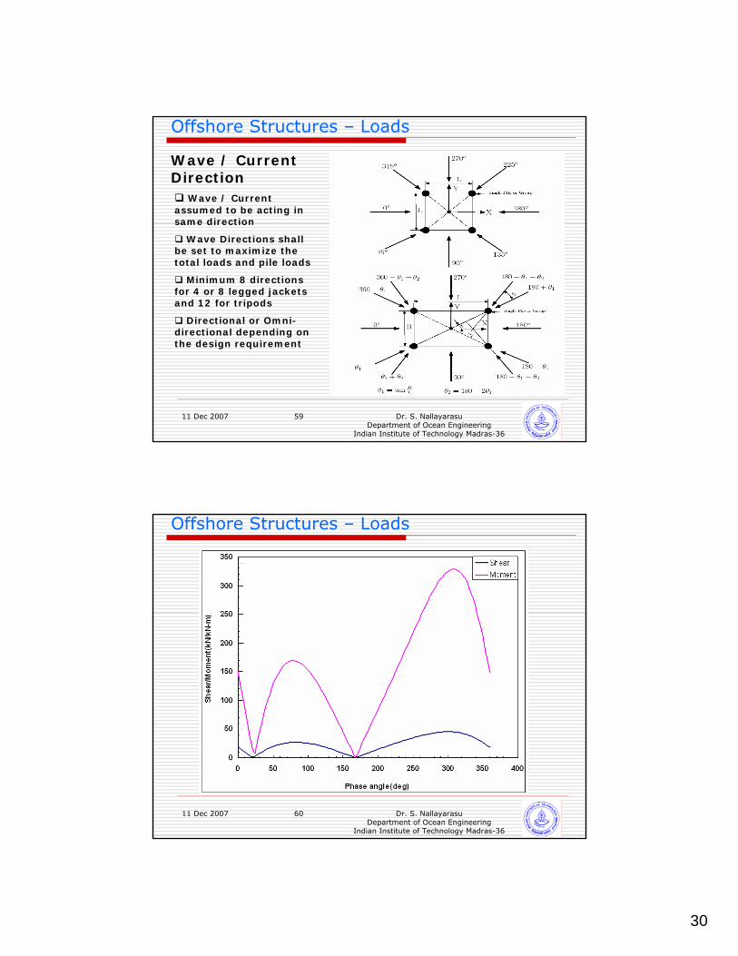
Wave / Current Direction
Wave / Current assumed to be acting in same direction
Wave Directions shall be set to maximize the total loads and pile loads
Minimum 8 directions for 4 or 8 legged jackets and 12 for tripods
Directional or Omni-directional depending on the design requirement
11 Dec 2007 Dr. S. NallayarasuDepartment of Ocean Engineering
Indian Institute of Technology Madras-36
60
Offshore Structures – Loads
31
11 Dec 2007 Dr. S. NallayarasuDepartment of Ocean Engineering
Indian Institute of Technology Madras-36
61
Offshore Structures – Loads
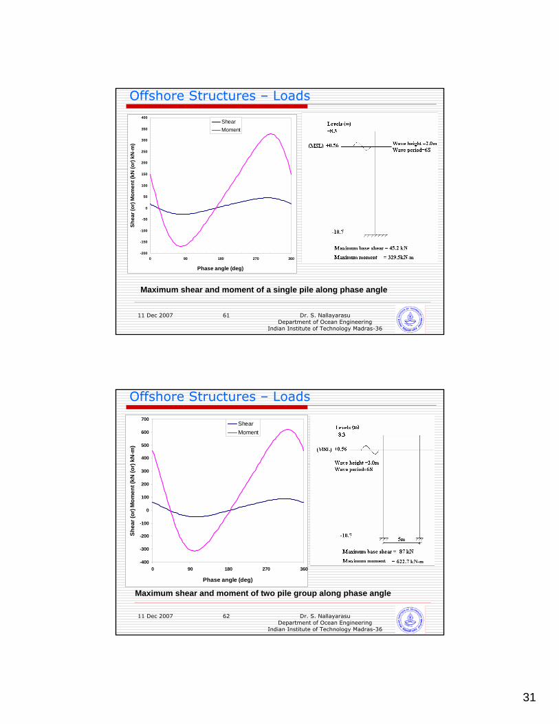
Maximum shear and moment of a single pile along phase angle
-200
-150
-100
-50
0
50
100
150
200
250
300
350
400
0 90 180 270 360
Phase angle (deg)
Shea
r (or
) Mom
ent (
kN (o
r) kN
-m)
ShearMoment
11 Dec 2007 Dr. S. NallayarasuDepartment of Ocean Engineering
Indian Institute of Technology Madras-36
62
Offshore Structures – Loads
-400
-300
-200
-100
0
100
200
300
400
500
600
700
0 90 180 270 360
Phase angle (deg)
Shea
r (or
) Mom
ent (
kN (o
r) kN
-m)
ShearMoment
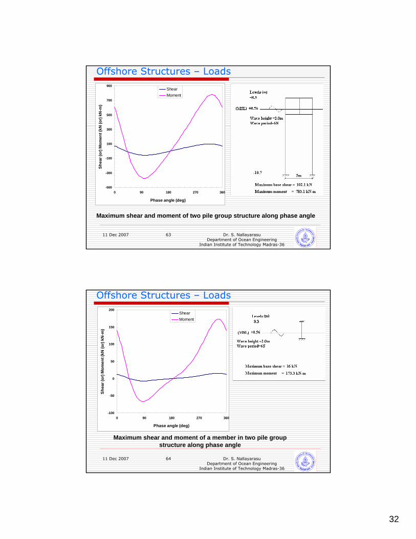
Maximum shear and moment of two pile group along phase angle
32
11 Dec 2007 Dr. S. NallayarasuDepartment of Ocean Engineering
Indian Institute of Technology Madras-36
63
Offshore Structures – Loads
Maximum shear and moment of two pile group structure along phase angle
-500
-300
-100
100
300
500
700
900
0 90 180 270 360
Phase angle (deg)
Shea
r (or
) Mom
ent (
kN (o
r) kN
-m)
ShearMoment
11 Dec 2007 Dr. S. NallayarasuDepartment of Ocean Engineering
Indian Institute of Technology Madras-36
64
Offshore Structures – Loads
-100
-50
0
50
100
150
200
0 90 180 270 360
Phase angle (deg)
Shea
r (or
) Mom
ent (
kN (o
r) kN
-m)
ShearMoment
Maximum shear and moment of a member in two pile group structure along phase angle
33
11 Dec 2007 Dr. S. NallayarasuDepartment of Ocean Engineering
Indian Institute of Technology Madras-36
65
Offshore Structures – Loads
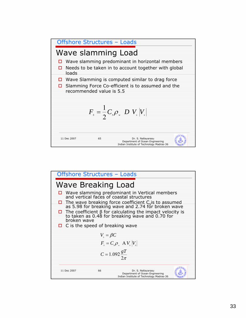
Wave slamming LoadWave slamming predominant in horizontal membersNeeds to be taken in to account together with global loadsWave Slamming is computed similar to drag forceSlamming Force Co-efficient is to assumed and the recommended value is 5.5
sswSSVVDCF
21 ρ=
11 Dec 2007 Dr. S. NallayarasuDepartment of Ocean Engineering
Indian Institute of Technology Madras-36
66
Offshore Structures – Loads
Wave Breaking LoadWave slamming predominant in Vertical members and vertical faces of coastal structuresThe wave breaking force coefficient Csis to assumed as 5.98 for breaking wave and 2.74 for broken waveThe coefficient β for calculating the impact velocity is to taken as 0.48 for breaking wave and 0.70 for broken waveC is the speed of breaking wave
π
ρ
β
2092.1
A gTC
VVCFCV
bbwbb
b
=
=
=
34
11 Dec 2007 Dr. S. NallayarasuDepartment of Ocean Engineering
Indian Institute of Technology Madras-36
67
Offshore Structures – Loads
FLOW INDUCED VIBRATION
11 Dec 2007 Dr. S. NallayarasuDepartment of Ocean Engineering
Indian Institute of Technology Madras-36
68
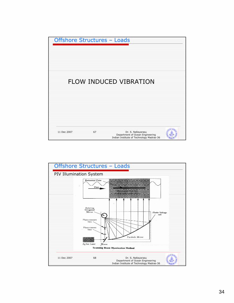
Offshore Structures – LoadsPIV Illumination System
35
11 Dec 2007 Dr. S. NallayarasuDepartment of Ocean Engineering
Indian Institute of Technology Madras-36
69
Offshore Structures – LoadsPIV Illumination System
11 Dec 2007 Dr. S. NallayarasuDepartment of Ocean Engineering
Indian Institute of Technology Madras-36
70
Offshore Structures – LoadsPIV Illumination System

36
11 Dec 2007 Dr. S. NallayarasuDepartment of Ocean Engineering
Indian Institute of Technology Madras-36
71
Offshore Structures – LoadsTypical PIV Image
11 Dec 2007 Dr. S. NallayarasuDepartment of Ocean Engineering
Indian Institute of Technology Madras-36
72
Offshore Structures – LoadsImage Showing Vortex at the tail end
37
11 Dec 2007 Dr. S. NallayarasuDepartment of Ocean Engineering
Indian Institute of Technology Madras-36
73
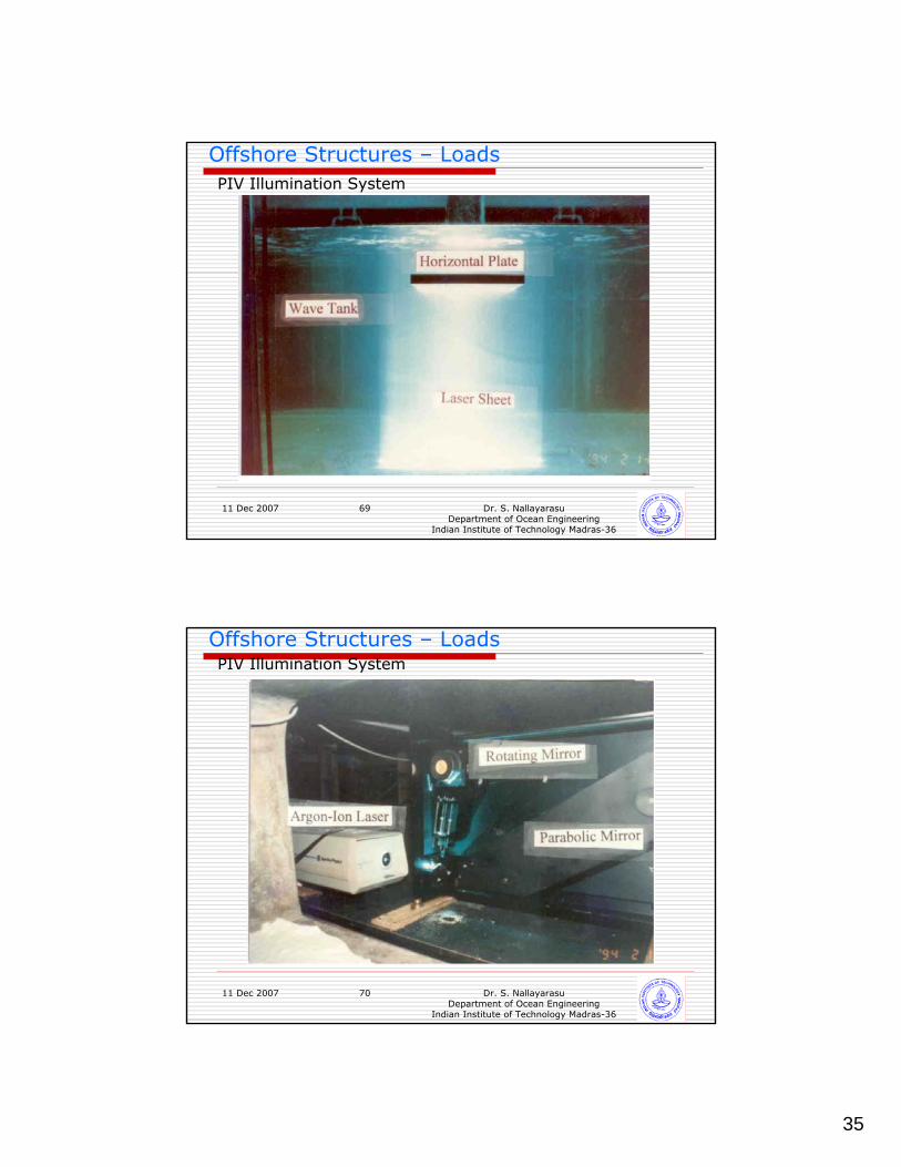
Offshore Structures – LoadsImage Showing Vortex developing further
11 Dec 2007 Dr. S. NallayarasuDepartment of Ocean Engineering
Indian Institute of Technology Madras-36
74
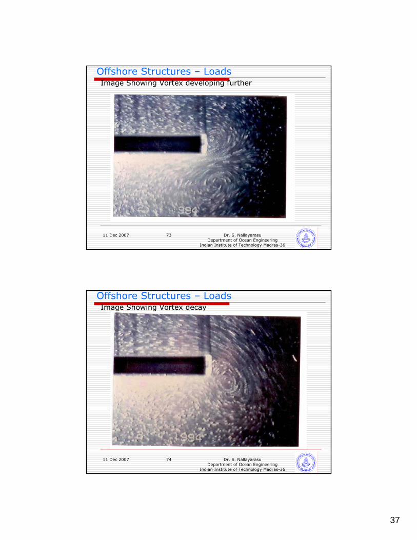
Offshore Structures – LoadsImage Showing Vortex decay
38
11 Dec 2007 Dr. S. NallayarasuDepartment of Ocean Engineering
Indian Institute of Technology Madras-36
75
Offshore Structures – Loads
FLOW PAST HORIZONTAL CYCLINDER
11 Dec 2007 Dr. S. NallayarasuDepartment of Ocean Engineering
Indian Institute of Technology Madras-36
76
Offshore Structures – Loads
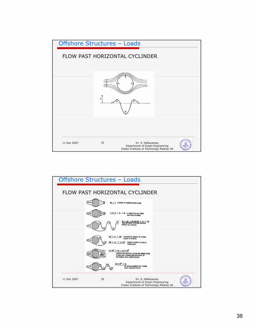
FLOW PAST HORIZONTAL CYCLINDER
39
11 Dec 2007 Dr. S. NallayarasuDepartment of Ocean Engineering
Indian Institute of Technology Madras-36
77
Offshore Structures – Loads
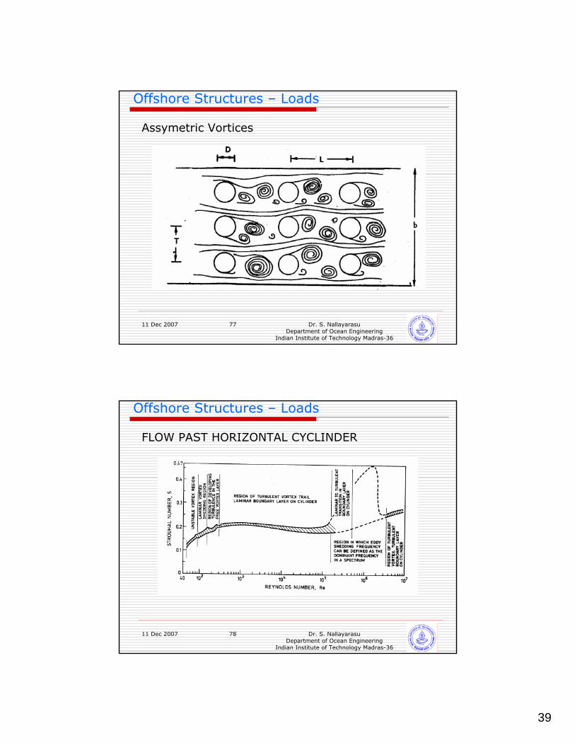
Assymetric Vortices
11 Dec 2007 Dr. S. NallayarasuDepartment of Ocean Engineering
Indian Institute of Technology Madras-36
78
Offshore Structures – Loads
FLOW PAST HORIZONTAL CYCLINDER
40
11 Dec 2007 Dr. S. NallayarasuDepartment of Ocean Engineering
Indian Institute of Technology Madras-36
79
Offshore Structures – Loads
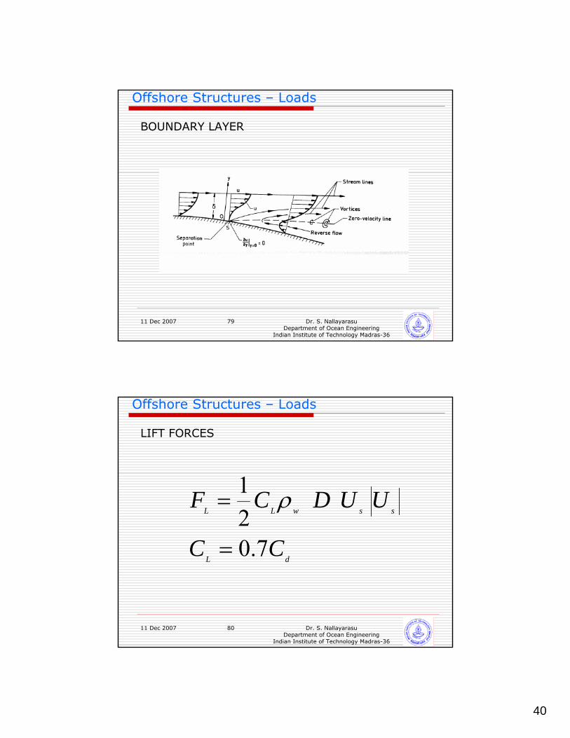
BOUNDARY LAYER
11 Dec 2007 Dr. S. NallayarasuDepartment of Ocean Engineering
Indian Institute of Technology Madras-36
80
Offshore Structures – Loads
LIFT FORCES
dL
sswLL
CC
UUDCF
7.0
21
=
= ρ
41
11 Dec 2007 Dr. S. NallayarasuDepartment of Ocean Engineering
Indian Institute of Technology Madras-36
81
Offshore Structures – Loads
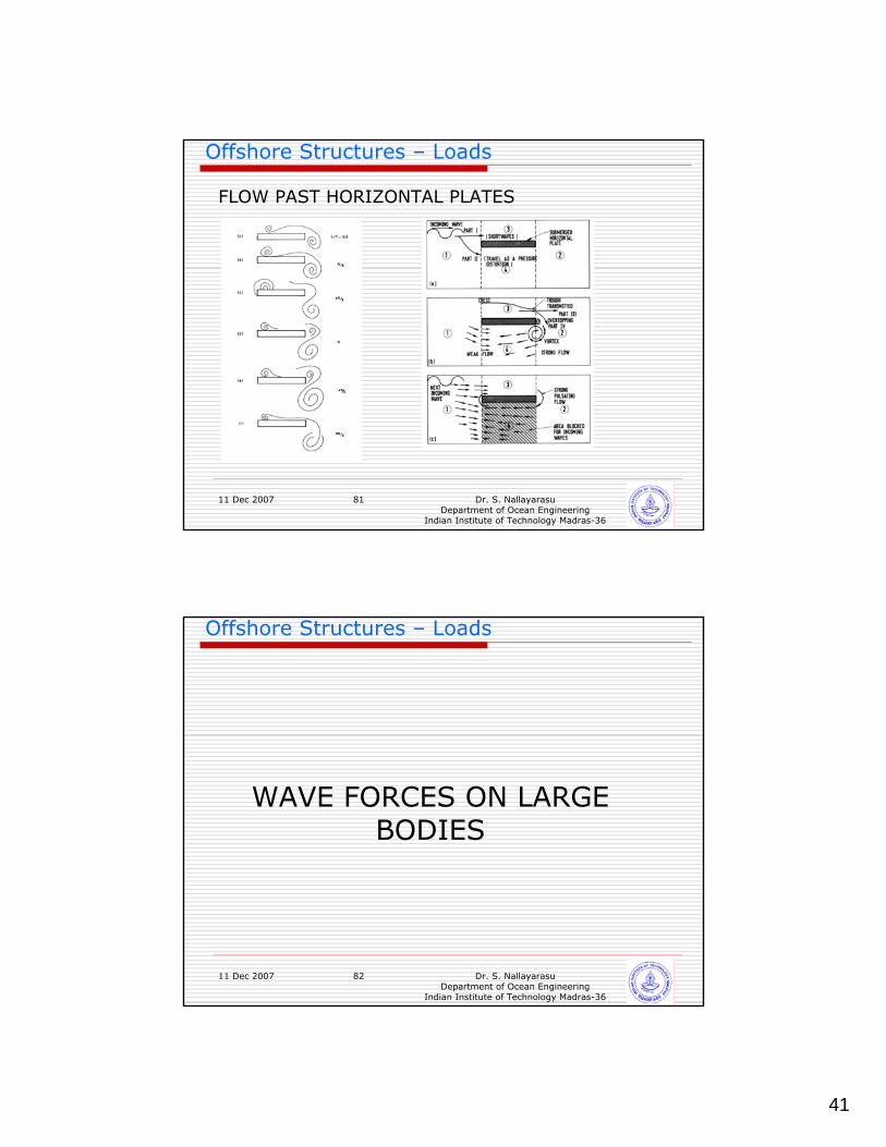
FLOW PAST HORIZONTAL PLATES
11 Dec 2007 Dr. S. NallayarasuDepartment of Ocean Engineering
Indian Institute of Technology Madras-36
82
Offshore Structures – Loads
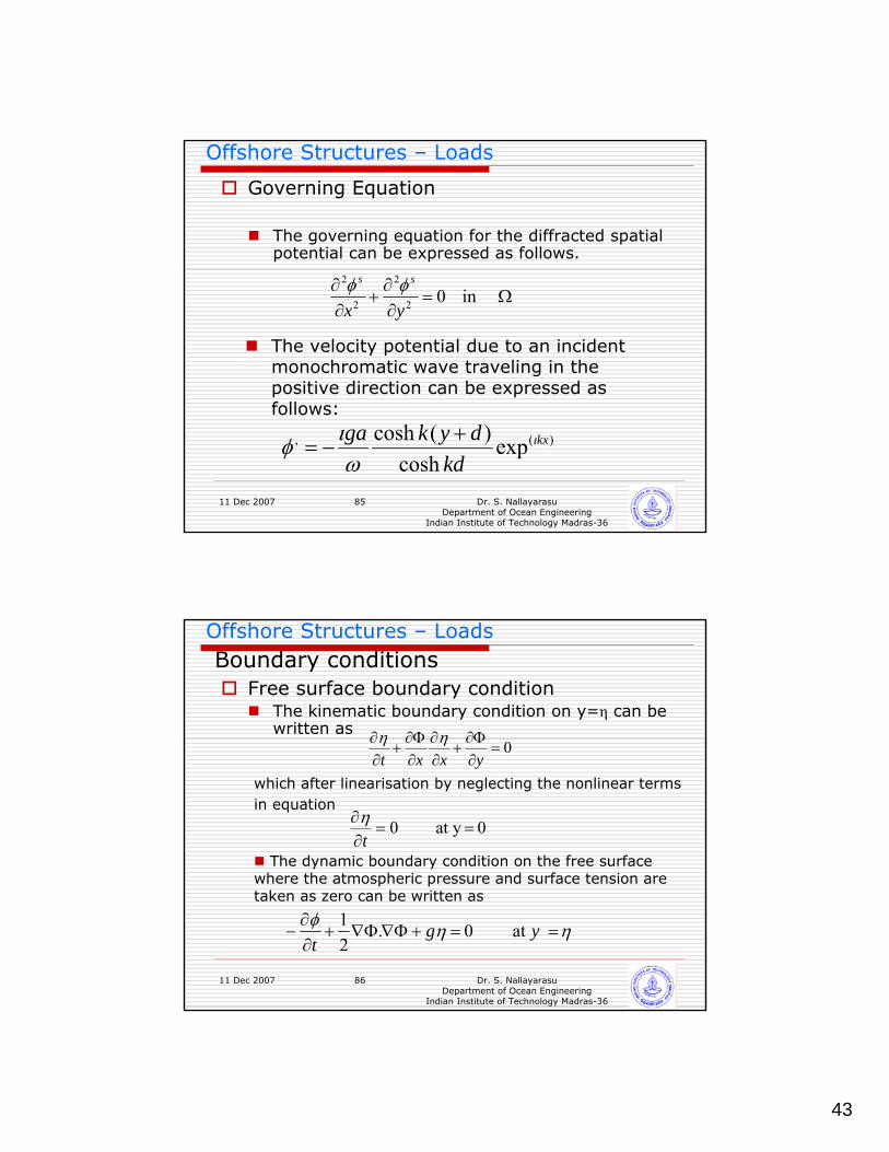
WAVE FORCES ON LARGE BODIES
42
11 Dec 2007 Dr. S. NallayarasuDepartment of Ocean Engineering
Indian Institute of Technology Madras-36
83
Offshore Structures – Loads
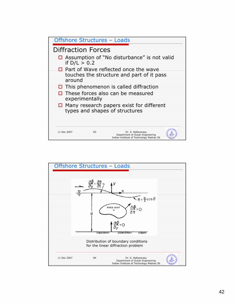
Assumption of “No disturbance” is not valid if D/L > 0.2 Part of Wave reflected once the wave touches the structure and part of it pass aroundThis phenomenon is called diffractionThese forces also can be measured experimentallyMany research papers exist for different types and shapes of structures
Diffraction Forces
11 Dec 2007 Dr. S. NallayarasuDepartment of Ocean Engineering
Indian Institute of Technology Madras-36
84
Offshore Structures – Loads
Distribution of boundary conditions for the linear diffraction problem
43
11 Dec 2007 Dr. S. NallayarasuDepartment of Ocean Engineering
Indian Institute of Technology Madras-36
85
Offshore Structures – Loads
Governing Equation
The governing equation for the diffracted spatial potential can be expressed as follows.
Ω=∂∂
+∂∂ in 02
2
2
2
yx
ss φφ
The velocity potential due to an incident monochromatic wave traveling in the positive direction can be expressed as follows:
)(, expcosh
)(cosh kx
kddykga ι
ωιφ +
−=
11 Dec 2007 Dr. S. NallayarasuDepartment of Ocean Engineering
Indian Institute of Technology Madras-36
86
Offshore Structures – LoadsBoundary conditions
Free surface boundary condition The kinematic boundary condition on y=η can be written as
0=∂Φ∂
+∂∂
∂Φ∂
+∂∂
yxxtηη
which after linearisation by neglecting the nonlinear terms in equation
The dynamic boundary condition on the free surface where the atmospheric pressure and surface tension are taken as zero can be written as
0 y at 0 ==∂∂
tη
ηηφ at 0 .21
==+Φ∇Φ∇+∂∂
− y gt
44
11 Dec 2007 Dr. S. NallayarasuDepartment of Ocean Engineering
Indian Institute of Technology Madras-36
87
Offshore Structures – Loads
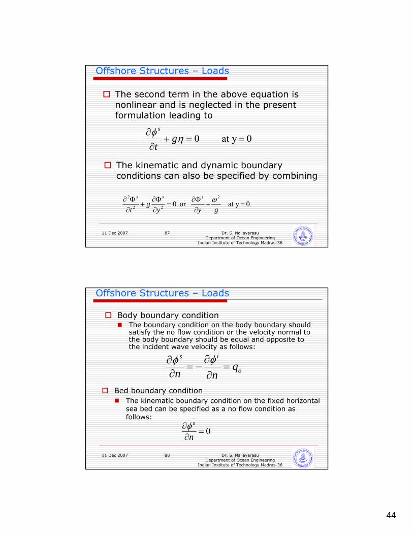
The second term in the above equation is nonlinear and is neglected in the present formulation leading to
0 y at 0 ==+∂∂ ηφ g
t
s
0 y at or 02
22
2
=+∂Φ∂
=∂Φ∂
+∂Φ∂
gyyg
t
sss ω
The kinematic and dynamic boundary conditions can also be specified by combining
11 Dec 2007 Dr. S. NallayarasuDepartment of Ocean Engineering
Indian Institute of Technology Madras-36
88
Offshore Structures – Loads
Body boundary conditionThe boundary condition on the body boundary should satisfy the no flow condition or the velocity normal to the body boundary should be equal and opposite to the incident wave velocity as follows:
o
is
qnn =∂∂
−=∂∂ φφ
Bed boundary conditionThe kinematic boundary condition on the fixed horizontal sea bed can be specified as a no flow condition as follows:
0=∂∂
−
n
sφ
45
11 Dec 2007 Dr. S. NallayarasuDepartment of Ocean Engineering
Indian Institute of Technology Madras-36
89
Offshore Structures – Loads
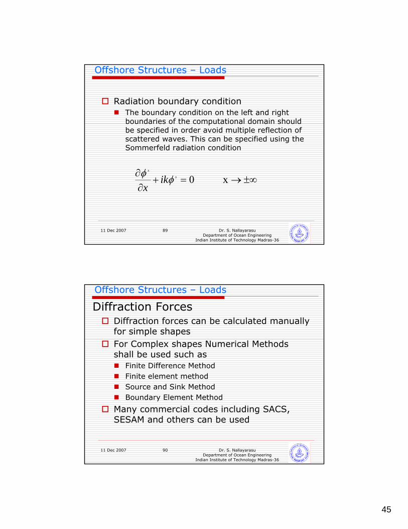
Radiation boundary conditionThe boundary condition on the left and right boundaries of the computational domain should be specified in order avoid multiple reflection of scattered waves. This can be specified using the Sommerfeld radiation condition
±∞→=+∂∂ x 0s
s
ikx
φφ
11 Dec 2007 Dr. S. NallayarasuDepartment of Ocean Engineering
Indian Institute of Technology Madras-36
90
Offshore Structures – Loads
Diffraction forces can be calculated manually for simple shapesFor Complex shapes Numerical Methods shall be used such as
Finite Difference MethodFinite element methodSource and Sink MethodBoundary Element Method
Many commercial codes including SACS, SESAM and others can be used
Diffraction Forces
46
11 Dec 2007 Dr. S. NallayarasuDepartment of Ocean Engineering
Indian Institute of Technology Madras-36
91
Offshore Structures – Loads
Solution of Boundary Value Problem for Velocity PotentialCalculation of PressuresIntegration of Pressures to obtain Forces
Diffraction Forces
11 Dec 2007 Dr. S. NallayarasuDepartment of Ocean Engineering
Indian Institute of Technology Madras-36
92
Offshore Structures – Loads
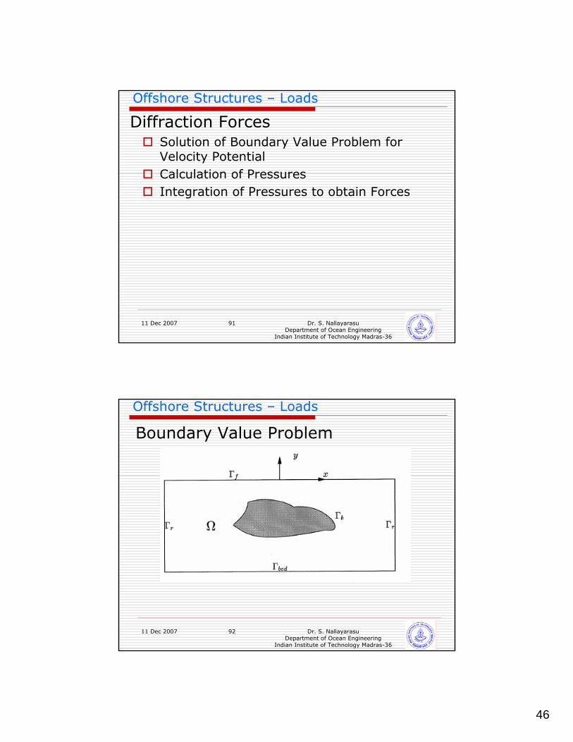
Boundary Value Problem
47
11 Dec 2007 Dr. S. NallayarasuDepartment of Ocean Engineering
Indian Institute of Technology Madras-36
93
Offshore Structures – Loads
Diffraction Forces
11 Dec 2007 Dr. S. NallayarasuDepartment of Ocean Engineering
Indian Institute of Technology Madras-36
94
Offshore Structures – Loads
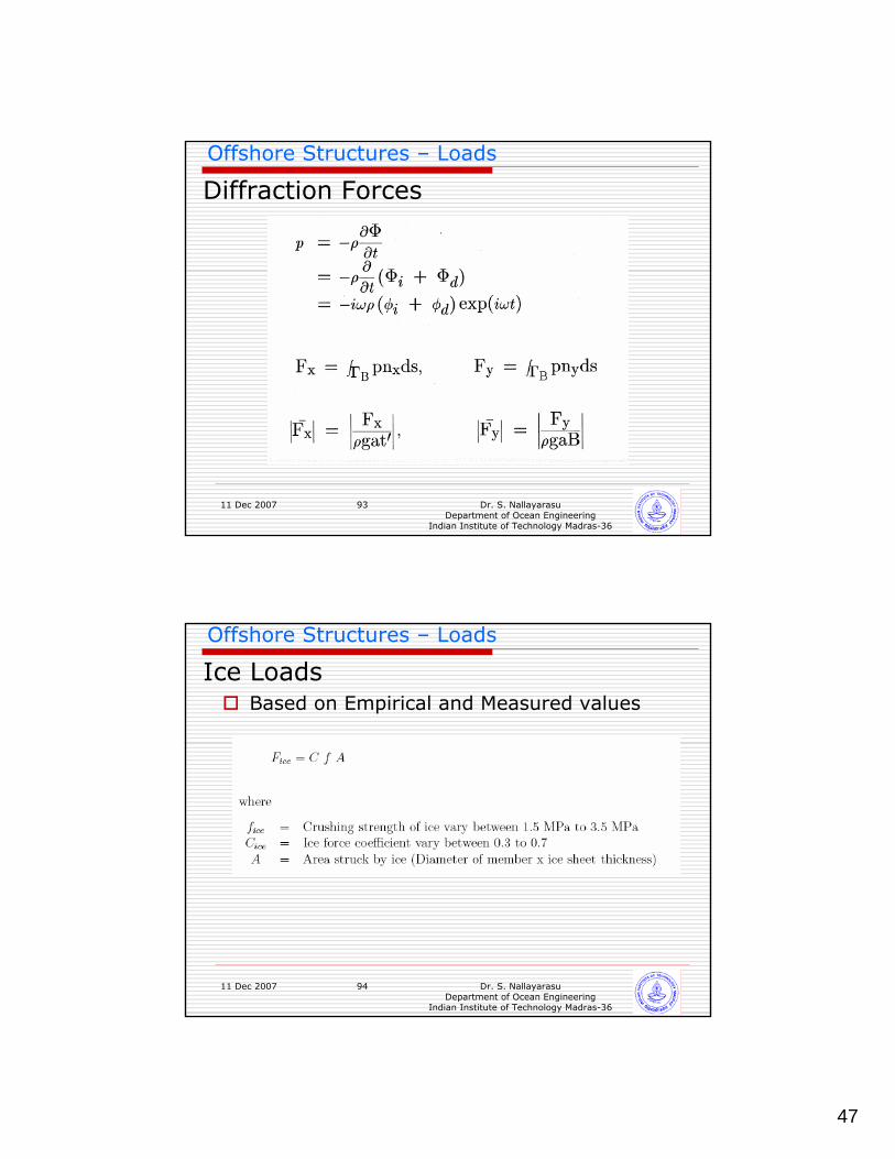
Based on Empirical and Measured values
Ice Loads
48
11 Dec 2007 Dr. S. NallayarasuDepartment of Ocean Engineering
Indian Institute of Technology Madras-36
95
Offshore Structures – Loads
ICE LOADS