Embed Size (px)
Citation preview
1
Links and LANs
EE 122: Intro to Communication Networks
Fall 2010 (MW 4-5:30 in 101 Barker)
Scott Shenker
TAs: Sameer Agarwal, Sara Alspaugh, Igor Ganichev, Prayag Narula
http://inst.eecs.berkeley.edu/~ee122/
Materials with thanks to Jennifer Rexford, Ion Stoica, Vern Paxsonand other colleagues at Princeton and UC Berkeley

Your Future?
• Who is planning to go to grad school (in CS)?
• Who is interested in research possibilities?
2

Regrading of Homework
• Requests for regrading must be made within one week of when the work was returned.
• To ask for a regrade, attach a page that specifies: – The problem(s) you want to be regraded– For each of these problems specify clearly why do
you think the problem was misgraded
• Without this page, your work will not be regraded.
• Your entire homework may be regraded– Score could decrease, stay the same, or increase
3

Other Announcements
• Won’t finish topic (links/LANs) today– It is your responsibility to slow me down– Ask questions, yawn loudly, snore, whatever it takes!
• Will continue into next Monday’s lecture….
4

5
Goals of Today’s Lecture
• Link-layer services
• Arbitrating access to a shared medium
• Random Access MAC (Media Access Control)
• Ethernet: single segment
• Ethernet: spanning multiple segments [Monday]
• Spanning trees [Monday]

6
Link-Layer Services

7
Message, Segment, Packet, and Frame
HTTP
TCP
IP
Ethernetinterface
HTTP
TCP
IP
Ethernetinterface
IP IP
Ethernetinterface
Ethernetinterface
SONETinterface
SONETinterface
host host
router router
HTTP message
TCP segment
IP packet IP packetIP packet
Ethernet frame Ethernet frameSONET frame

Today We Focus on Link-Layer
8
Ethernetinterface
Ethernetinterface
Ethernetinterface
Ethernetinterface
SONETinterface
SONETinterface
Ethernet frame Ethernet frameSONET frame
• What functions these technologies provide
• How they implement those functions

9
Adaptor-to-Adaptor Communication
• Link layer implemented in adaptor (network interface card; NIC)– Ethernet card, 802.11 card (why?)
• Sending side:– Encapsulates datagram in a frame– Determines local addressing, adds error checking, controls
transmission
• Receiving side– Recognizes arrival, looks for errors, possibly acknowledges– Extracts datagram and passes to receiving node
sendingnode
frame
receivingnode
datagram
frame
adaptor adaptor
link layer protocol

10
Link-Layer Services
• Encoding– Representing the 0s and 1s
• Framing– Encapsulating packet into frame, adding header, trailer– Using MAC addresses rather than IP addresses
• Error detection– Errors caused by signal attenuation, noise – Receiver detects presence, may ask for repeat (ARQ)
• Resolving contention– Deciding who gets to transmit when multiple senders
want to use a shared media
• Flow control (pacing between sender & receiver)

11
Framing
• Specify how blocks of data are transmitted between two nodes connected on the same physical media– Service provided by the data link layer– Implemented by the network adaptor
• Challenges– Decide when a frame starts & ends– How hard can that be?
12
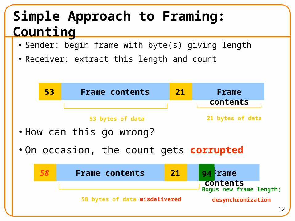
Simple Approach to Framing: Counting
• Sender: begin frame with byte(s) giving length
• Receiver: extract this length and count
• How can this go wrong?
• On occasion, the count gets corrupted
53 Frame contents
53 bytes of data
21 Frame contents
21 bytes of data
58 Frame contents 21 Frame contents
58 bytes of data misdelivered
94
Bogus new frame length;
desynchronization

Desynchronization
• Once framing is desynchronized, stays that way
• Need a method to resynchronize
• But once we have that method, why use counting?
• Sounds like E2E-like argument….
13

14
Framing: Sentinels
• Delineate frame with special pattern– e.g., 01111110 start, 01111111 end
• Problem: what if sentinel occurs within frame?
• Solution: escape the special characters– E.g., sender always inserts a 0 after five 1s– … receiver always removes a 0 appearing after five 1s
• Similar to escaping special characters in C programs
01111110 01111111Frame contents

15
When Receiver Sees Five 1s
• If next bit 0, remove it, and begin counting again– Because this must be stuffed bit– Can’t be at beginning/end of frame
• If next bit 1, then:– If following bit is 0, this is start of frame
o receiver has seen 01111110– If following bit is 1, this is end of frame
o receiver has seen 01111111
01111110 01111111Frame content

Example
01111110 0111111011111011111001 01111111
16
01111110 0111110101111100111110001 01111111
01111110 0111111011111011111001 01111111
Sender: Five 1s insert a 0
Start frame
Five 1s and next bit 0 remove it
Receiver:
End frame

Sentinels and Synchronization
• Can Sentinels ever get desynchronized?
• No! Every analysis of start/end is independent
17

18
Clock-Based Framing (SONET)
• SONET (Synchronous Optical NETwork)
• SONET endpoints maintain clock synchronization
• Frames have fixed size (e.g., 125 sec)
• No ambiguity about start & stop of frame– But may be wasteful
• NRZ encoding– To avoid long sequences of 0’s or 1’s payload is XOR-ed
with special 127-bit pattern w/ many 0-1/1-0 transitions

19
Error Detection
• Errors are unavoidable– Electrical interference, thermal noise, etc.
• Error detection– Transmit extra (redundant) information – Use redundant information to detect errors– Extreme case: send two copies of the data– Trade-off: accuracy vs. overhead
• Techniques for detecting errors– Parity checking– Checksum– Cyclic Redundancy Check (CRC)

20
Error Detection: Parity
• Add an extra bit to a 7-bit code
• Odd parity: ensure an odd number of 1s– E.g., 0101011 becomes 01010111
• Even parity: ensure an even number of 1s– E.g., 0101011 becomes 01010110
• Overhead: 1/7th
• Power: – Detects all 1-bit errors– But: can’t detect an even number of bit errors in a word
• Can use more bits to gain more power

21
Error Detection: Internet Checksum
• Treat data as a sequence of 16-bit words
• Compute ones-complement sum of all 16-bit words
• Intermingles integrity of a large group of data
• Overhead: 16 bits
• Power:– Catches 1-bit errors, most other errors– But not, e.g., same bit flipped in two different words

22
Error Detection: CRC
• Family of powerful and principled algorithms– Detects wide range of bit corruption patterns seen in
practice
• Used by most modern link layers
• See K&R Section 5.2.3
• Why do links use CRC but IP uses checksum?

23
Arbitrating Access in Shared Media

24
Point-to-Point vs. Broadcast Media
• Point-to-point: dedicated pairwise communication– Long-distance fiber link– Point-to-point link between Ethernet switch and host
• Broadcast: shared wire or medium– Traditional Ethernet– 802.11 wireless LAN

25
Multiple Access Algorithm
• Single shared broadcast channel– Must avoid having multiple nodes speaking at once– Otherwise, collisions lead to garbled data
• Multiple access mechanism– Distributed algorithm for sharing the channel– Algorithm determines which node can transmit
• Classes of techniques– Channel partitioning: divide channel into pieces– Taking turns: scheme for trading off who gets to transmit– Random access: allow collisions, and then recover
o Optimizes for the common case of only one sender
26
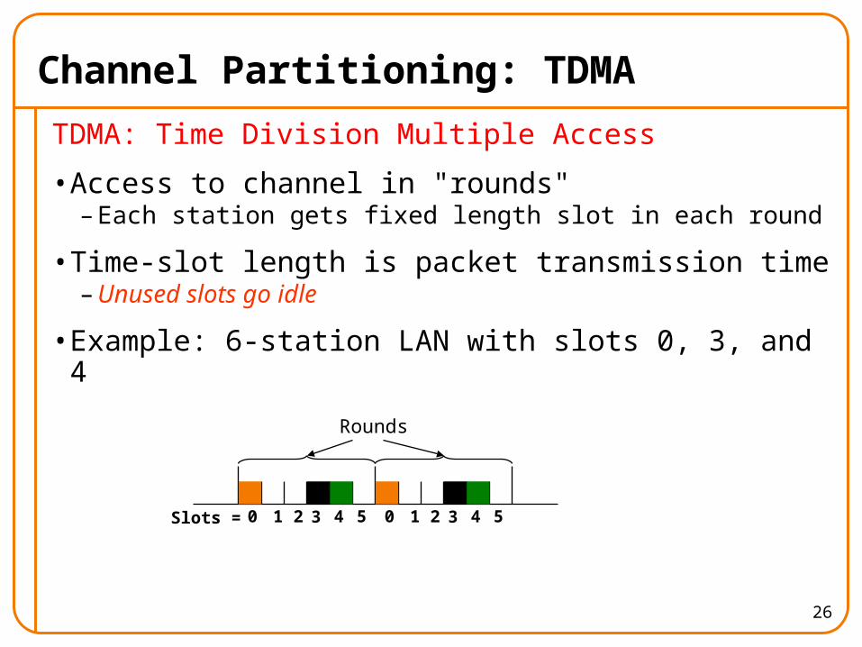
Channel Partitioning: TDMA
TDMA: Time Division Multiple Access
• Access to channel in "rounds" – Each station gets fixed length slot in each round
• Time-slot length is packet transmission time – Unused slots go idle
• Example: 6-station LAN with slots 0, 3, and 4Rounds
0 1 2 3 4 5 0 1 2 3 4 5Slots =

27
Channel Partitioning: FDMA
FDMA: Frequency Division Multiple Access
• Channel spectrum divided into frequency bands
• Each station assigned fixed frequency band
• Unused transmission time in frequency bands go idle
• Example: 6-station LAN, 1,3,4 have pkt, frequency bands 2,5,6 idle
frequ
ency
bands time
FDM cable

28
“Taking Turns” MAC protocols
Polling
• Master node “invites” slave nodes to transmit in turn
• Concerns:– Polling overhead – Latency– Single point of failure
(master)
Token passing
• Control token passed from one node to next sequentially
• Node must have token to send
• Concerns:– Token overhead – Latency– At mercy of any node
master
slaves
poll
data
data

Why Did Ethernet Beat Token Ring?
• Performance?– No!
• Latency?– No!
• Cost (i.e., simplicity)?– Yes!
• Reliability?– Yes!
29

30
5 Minute Break
Questions Before We Proceed?

31
Random Access MAC Protocols

32
Random Access MAC Protocols
• When node has packet to send– Transmit at full channel data rate– No a priori coordination among nodes
• Two or more transmitting nodes collision– Data lost
• Random access MAC protocol specifies: – How to detect collisions– How to recover from collisions
• Examples – ALOHA and Slotted ALOHA– CSMA, CSMA/CD, CSMA/CA (wireless, covered later)

33
Key Ideas of Random Access
• Carrier sense– Listen before speaking, and don’t interrupt– Checking if someone else is already sending data– … and waiting till the other node is done
• Collision detection– If someone else starts talking at the same time, stop– Realizing when two nodes are transmitting at once– …by detecting that the data on the wire is garbled
• Randomness– Don’t start talking again right away– Waiting for a random time before trying again

34
Where it all Started: AlohaNet
• Norm Abramson left Stanford to surf
• Set up first data communication system for Hawaiian islands
• Hub at U. Hawaii, Oahu
• Had two radio channels:– Random access:
o Sites sending data– Broadcast:
o Hub rebroadcasting data

35
Slotted ALOHA
Assumptions
• All frames same size
• Time divided into equal slots (time to transmit a frame)
• Nodes are synchronized
• Nodes begin to transmit frames only at start of slots
• If two or more nodes transmit, all nodes detect collision
Operation
• When node gets fresh data, transmits in next slot
• No collision: success!
• Collision: node retransmits frame in each subsequent slot with probability p until success

36
Slot-by-Slot Example

37
Efficiency of Slotted Aloha• What is the maximum fraction of successful
transmissions?
• Suppose N stations have packets to send– Each transmits in slot with probability p– Probability of successful transmission is roughly:
by a particular node i: Si = p (1-p)(N-1)
by exactly one of N nodes: S= N p (1-p)(N-1)
• Limiting behavior:– For fixed p, S 0 as N increases– But if p = 1/N, then S 1/e = 0.37 as N increases
• Max efficiency is only slightly greater than 1/3!

38
Pros and Cons of Slotted Aloha
Pros
• Single active node can continuously transmit at full rate of channel
• Highly decentralized: only need slot synchronization
• Simple
Cons
• Wasted slots:– Idle– Collisions
• Nodes should detect collision in less than time to transmit packet
• Clock synchronization

39
Improving on Slotted Aloha
• Fewer wasted slots– Need to decrease collisions and empty slots
• Don’t waste full slots on collisions– Need to decrease time to detect collisions
• Avoid need for synchronization– Synchronization is hard to achieve

40
CSMA (Carrier Sense Multiple Access)
• CSMA: listen before transmit– If channel sensed idle: transmit entire frame– If channel sensed busy, defer transmission
• Human analogy: don’t interrupt others!

41
CSMA Collisions
Collisions can still occur:propagation delay means two nodes may not heareach other’s transmission in time.
At time t1, D still hasn’t heard B’s signal sent at the earlier time t0, so D goes ahead and transmits: failure of carrier sense.
Collision: entire packet transmission time wasted
Do we still needs slots?Would slots hurt or help?

42
CSMA/CD (Collision Detection)
• CSMA/CD: carrier sensing, deferral as in CSMA– Collisions detected within short time– Colliding transmissions aborted, reducing wastage
• Collision detection easy in wired LANs:– Compare transmitted, received signals
• Collision detection difficult in wireless LANs:– Reception shut off while transmitting– Even if on, might not be able to hear the other sender,
even though the receiver can– Leads to use of collision avoidance instead (later)

43
CSMA/CD Collision Detection
Both B and D can tell that collision occurred.
This lets them (1) know that they need to resend the frame,and (2) recognize that there’s contention and adopt a strategy for dealing with it.
Note: for this to work, we need restrictions on minimum frame size and maximum distance

44
Limits on CSMA/CD Network Length
• Latency depends on physical length of link– Time to propagate a packet from one end to the other
• Suppose A sends a packet at time t– And B sees an idle line at a time just before t+d– … so B happily starts transmitting a packet
• B detects a collision, and sends jamming signal– But A can’t see collision until t+2d
latency dA B

45
Limits on CSMA/CD Network Length
• A needs to wait for time 2d to detect collision– So, A should keep transmitting during this period– … and keep an eye out for a possible collision
• Imposes restrictions. E.g., for 10 Mbps Ethernet:– Maximum length of the wire: 2,500 meters– Minimum length of a frame: 512 bits (64 bytes)
o 512 bits = 51.2 sec (at 10 Mbit/sec)o For light in vacuum, 51.2 sec ≈ 15,000 meters
vs. 5,000 meters “round trip” to wait for collision
latency dA B
46
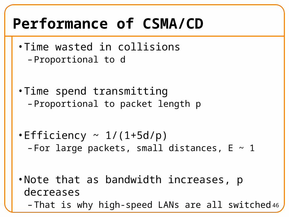
Performance of CSMA/CD
• Time wasted in collisions– Proportional to d
• Time spend transmitting– Proportional to packet length p
• Efficiency ~ 1/(1+5d/p)– For large packets, small distances, E ~ 1
• Note that as bandwidth increases, p decreases– That is why high-speed LANs are all switched

Game Theory?
• What happens when one node has CD and the other doesn’t?
• When do we see this in real life?
47

48
Ethernet (Single Segment)

49
Ethernet: CSMA/CD Protocol
• Carrier sense: wait for link to be idle
• Collision detection: listen while transmitting– No collision: transmission is complete– Collision: abort transmission & send jam signal
• Random access: binary exponential back-off– After collision, wait a random time before trying again– After mth collision, choose K randomly from {0, …, 2m-1}– … and wait for K*512 bit times before trying again
• The wired LAN technology– Hugely successful: 3/10/100/1000/10000 Mbps

50
Ethernet Frame Structure
• Sending adapter encapsulates packet in frame
• Preamble: synchronization– Seven bytes with pattern 10101010, followed by one
byte with pattern 10101011– Used to synchronize receiver & sender
• Type: indicates the higher layer protocol – Usually IP (but also Novell IPX, AppleTalk, …)
• CRC: cyclic redundancy check– Receiver checks & simply drops frames with errors

51
Ethernet Frame Structure (Continued)
• Addresses: 48-bit source and destination MAC addresses – Receiver’s adaptor passes frame to network-level protocol
o If destination address matches the adaptor’so Or the destination address is the broadcast address (ff:ff:ff:ff:ff:ff)o Or the destination address is a multicast group receiver belongs too Or the adaptor is in promiscuous mode
– Addresses are globally uniqueo Assigned by NIC vendors (top three octets specify vendor)
• During any given week, > 500 vendor codes seen at LBNL
• Data:– Maximum: 1,500 bytes– Minimum: 46 bytes (+14 bytes header + 4 byte trailer = 512 bits)

52
Ethernet, con’t
• Connectionless– No handshaking between sending and receiving adapter
• Unreliable– Receiving adapter doesn’t send ACKs or NACKs– Packets passed to network layer can have gaps– Gaps will be filled if application is using TCP– Otherwise, application will see the gaps
• 2,700 page IEEE 802.3 standardization– http://standards.ieee.org/getieee802/802.3.html
• Note, “classical” Ethernet has no length field …– … instead, sender pauses 9.2 sec when done– 802.3 shoehorns in a length field

53
Benefits of Ethernet
• Easy to administer and maintain
• Inexpensive
• Increasingly higher speed
• Evolvable

Evolution of Ethernet
• From shared media to switches– Why?
• From electrical signaling to also optical
• Changed everything except the frame format
• Lesson– The right interface can accommodate many changes – Implementation is hidden behind interface
54

BEB: Reality vs Theory
• In reality, binary exponential backoff (BEB)– Performs well– Is irrelevant (why?)
• In theory, a very interesting algorithm– Stability of algorithm for finite N only proved in 1985– All backoff algorithms unstable for infinite N (1985)
o Poisson model: infinite user pool, all with infinitesimal demand• Sums to finite load
55

MAC “Channel Capture” in BEB
• Two hosts, each with infinite packets to send
• With BEB, there is a finite chance that the first one to have a successful transmission will never relinquish the channel– The other host will never send a packet
56

Different Backoff Functions
• Exponential:– Channel capture– Efficiency less than 1
• Superlinear polynomial:– Channel capture– Efficiency is 1 (for any finite N)
• Sublinear polynomial:– No channel capture– Efficiency is less than 1 (and goes to zero for large N)
57
58
Next Lecture
• Finish up Links and LANs– Ethernet: spanning multiple segments– Spanning trees
• Remember:– HW #2 due– Project 1A due– Requests for regrades due