Embed Size (px)
Citation preview
1
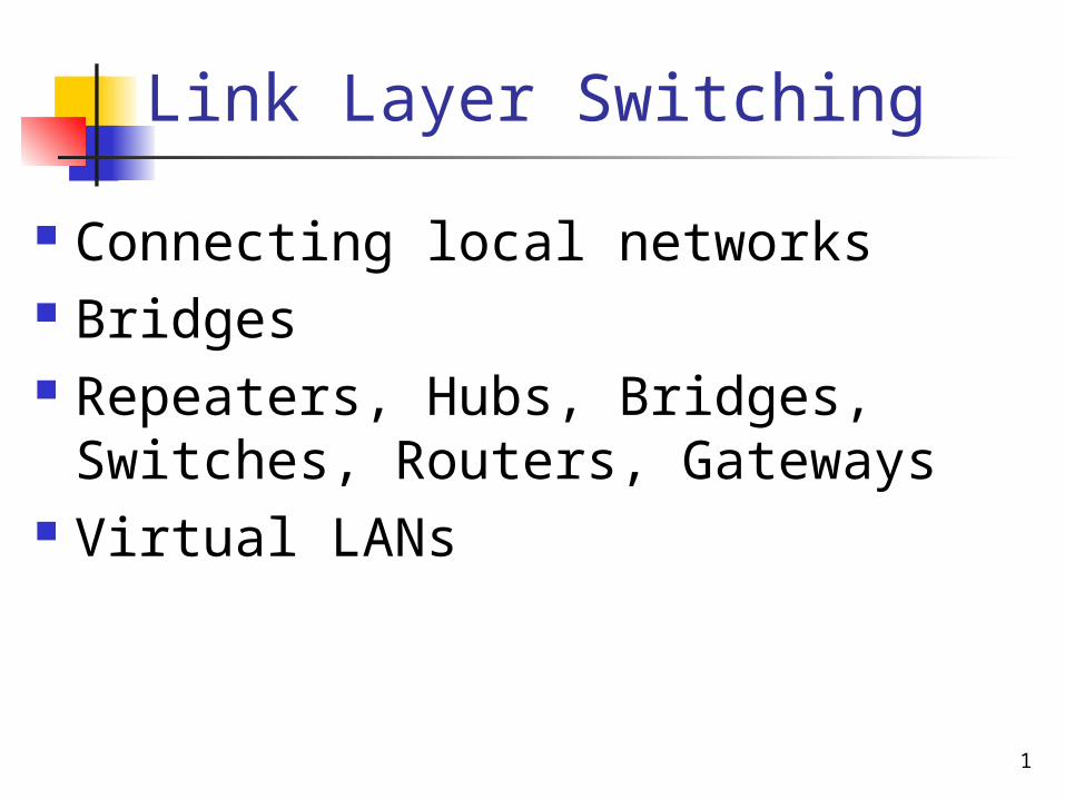
Link Layer Switching
Connecting local networks Bridges Repeaters, Hubs, Bridges, Switches,
Routers, Gateways Virtual LANs
2
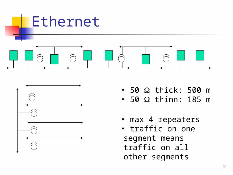
Ethernet
• 50 thick: 500 m• 50 thinn: 185 m
• max 4 repeaters• traffic on one segment means traffic on all other segments
3
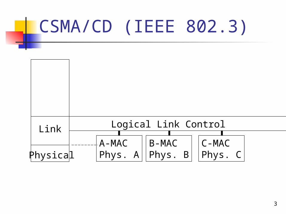
CSMA/CD (IEEE 802.3)
A-MACPhys. A
B-MACPhys. B
C-MACPhys. C
Logical Link Control
Physical
Link
4
Bridges
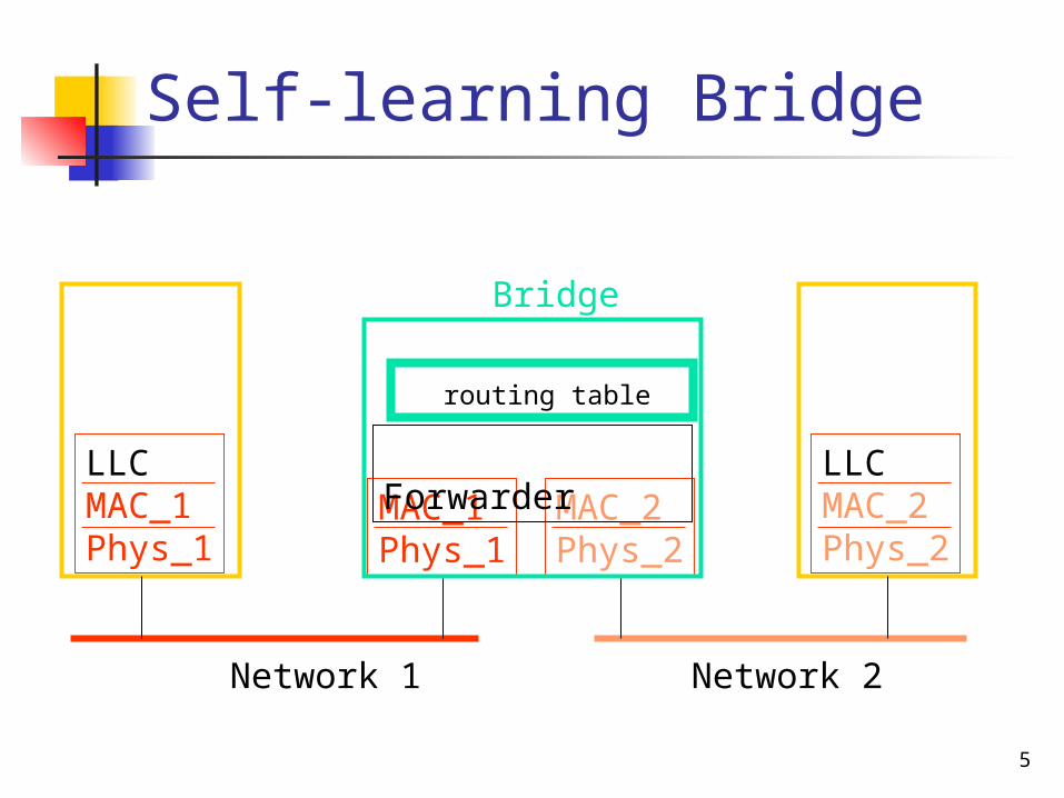
Connection on link layer: forwarding based on MAC addresses self-learning bridges
operation Advantages and limitations
Spanning-tree bridges operation Advantages and limitations
5
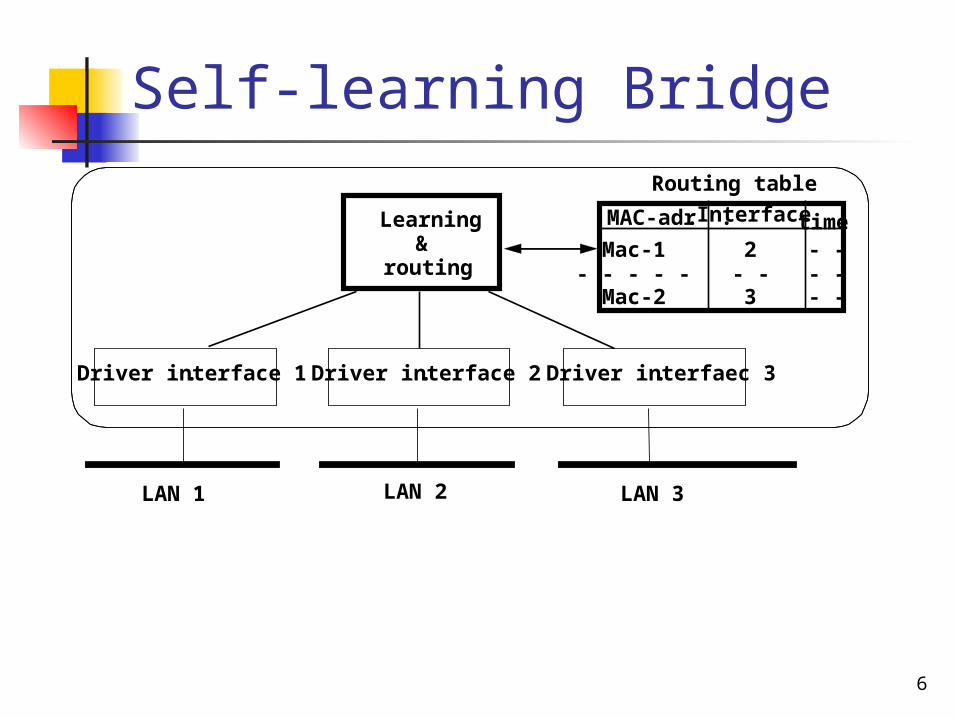
Self-learning Bridge
MAC_1Phys_1
LLCMAC_1Phys_1
MAC_2Phys_2
LLCMAC_2Phys_2
Forwarder
Bridge
routing table
Network 1 Network 2
6
Self-learning Bridge
Driver interface 1. Driver interfaec 3. Driver interface 2.
LAN 1 LAN 2 LAN 3
Learning&
routing
Routing table
MAC-adr. Interface. timeMac-1- - - - -Mac-2
2- - 3
- -- -- -
7
Self-learning Bridge
ExtractSender and receiver MAC-adresser
Updateinterface #and timer
New entryMAC-addrinterface #and timer
Start
Senderknown?
Yes No
Look up inRouting table
Receiverknown?
Broadcast frame, except on receiving
interface
Put frame intocorrectoutgoing queue
End
Learning phase Forwarding phase
Look up inRouting table
8
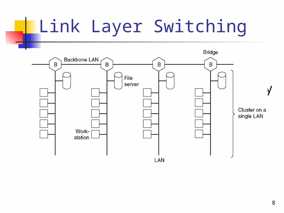
Link Layer Switching
Multiple LANs connected by a backbone to handle a total load
higher than the capacity of a single LAN.
9
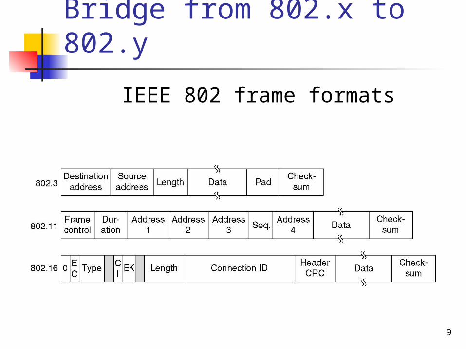
Bridge from 802.x to 802.y
IEEE 802 frame formats
10
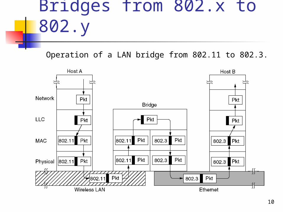
Bridges from 802.x to 802.y
Operation of a LAN bridge from 802.11 to 802.3.
11
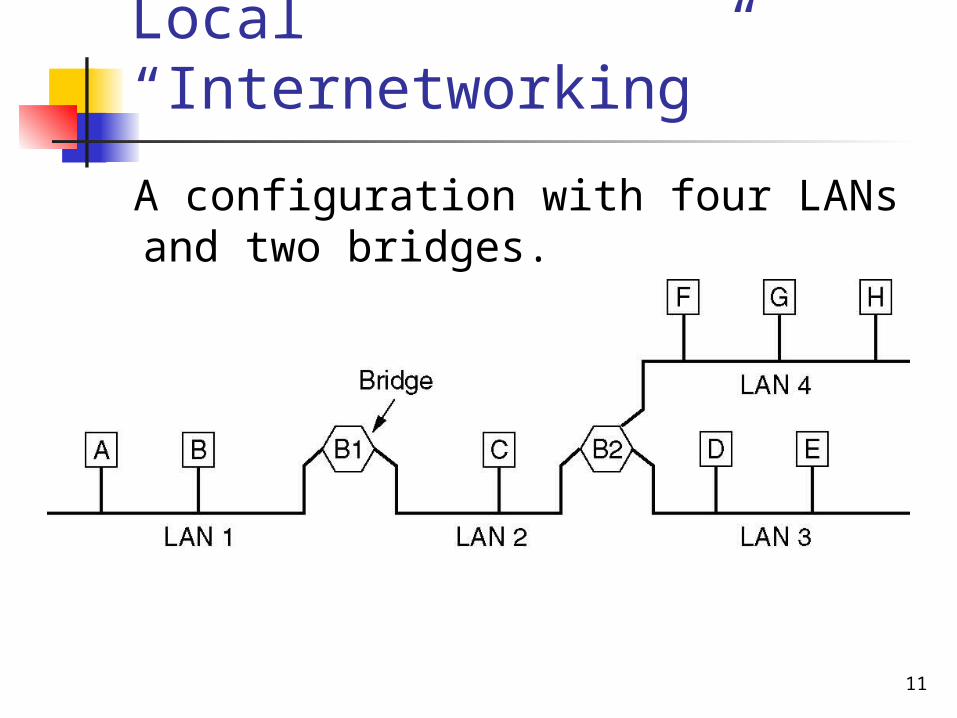
Local “Internetworking”
A configuration with four LANs and two bridges.
12
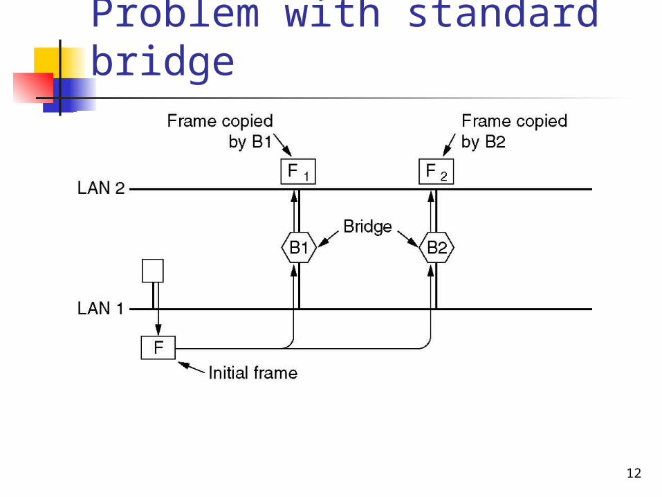
Problem with standard bridge
Two parallel transparent bridges.
13
Spanning tree
Goal: each bridge should identify the interfaes for forwarding traffic
Build a spanning tree From on root node
Self-configuring To all nodes
Only these interfaces in the spanning tree can forward traffic
Provides the shortest path for all traffic
14
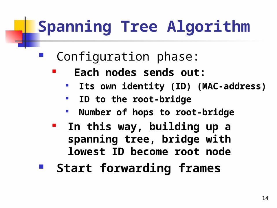
Spanning Tree Algorithm
Configuration phase: Each nodes sends out:
Its own identity (ID) (MAC-address) ID to the root-bridge Number of hops to root-bridge
In this way, building up a spanning tree, bridge with lowest ID become root node
Start forwarding frames
15
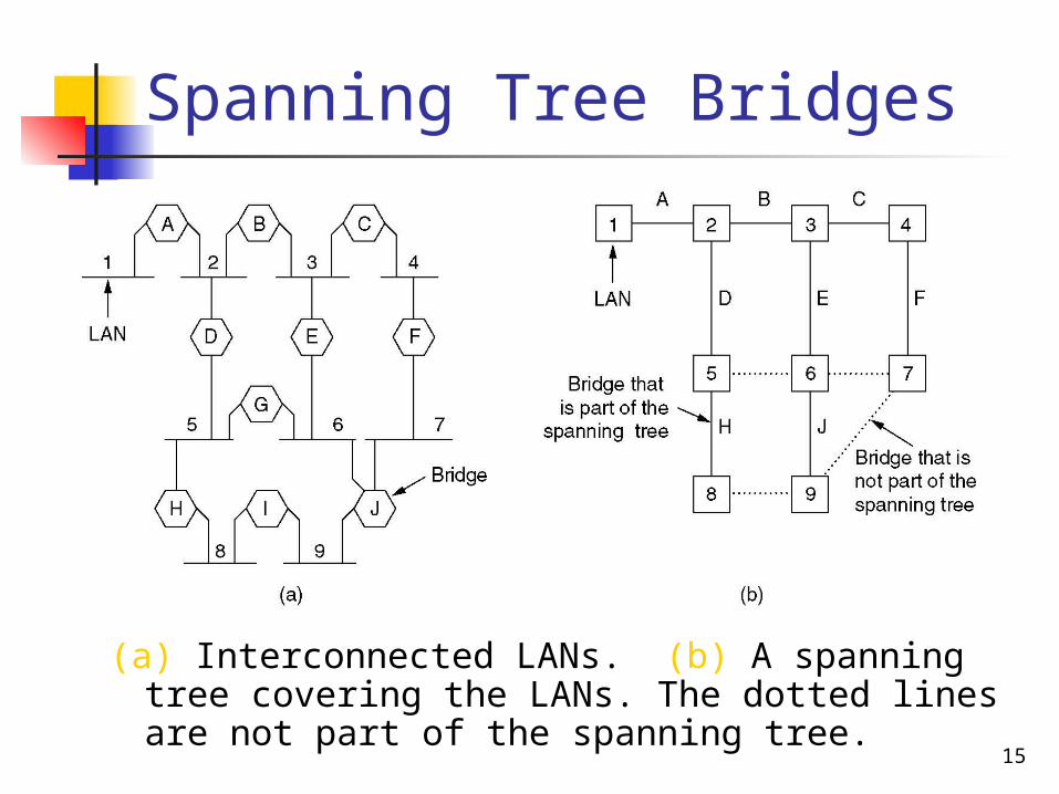
Spanning Tree Bridges
(a) Interconnected LANs. (b) A spanning tree covering the LANs. The dotted lines are not part of the spanning tree.
16
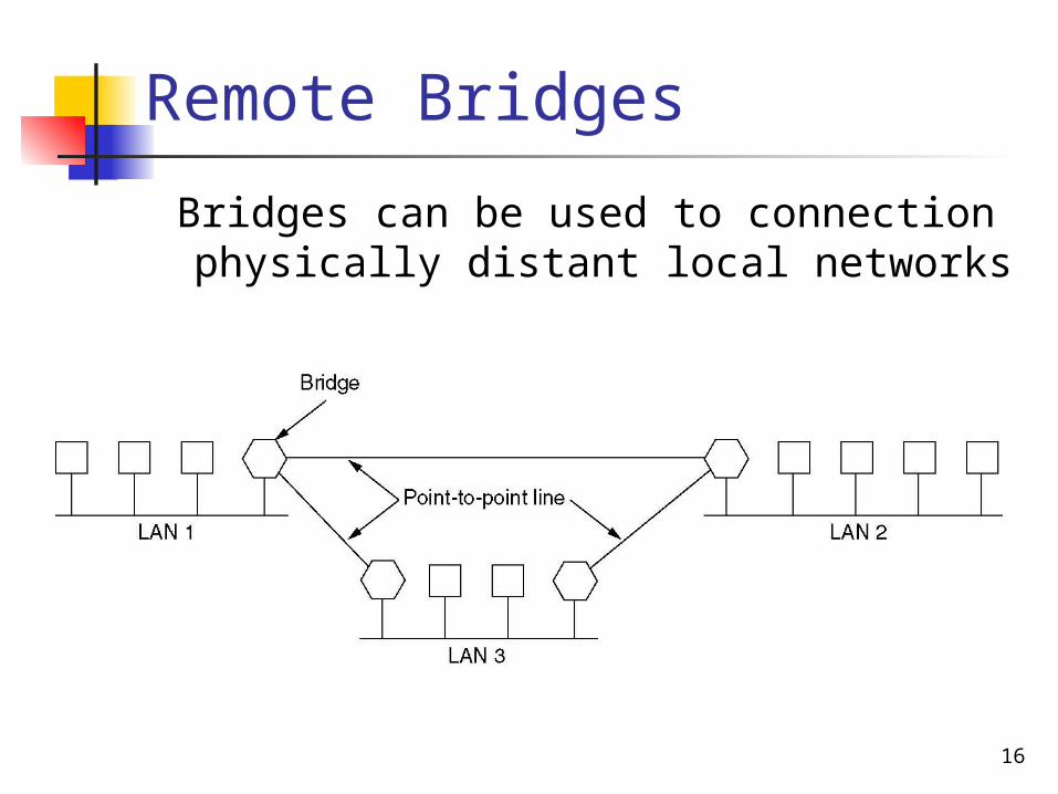
Remote Bridges
Bridges can be used to connection physically distant local networks
17
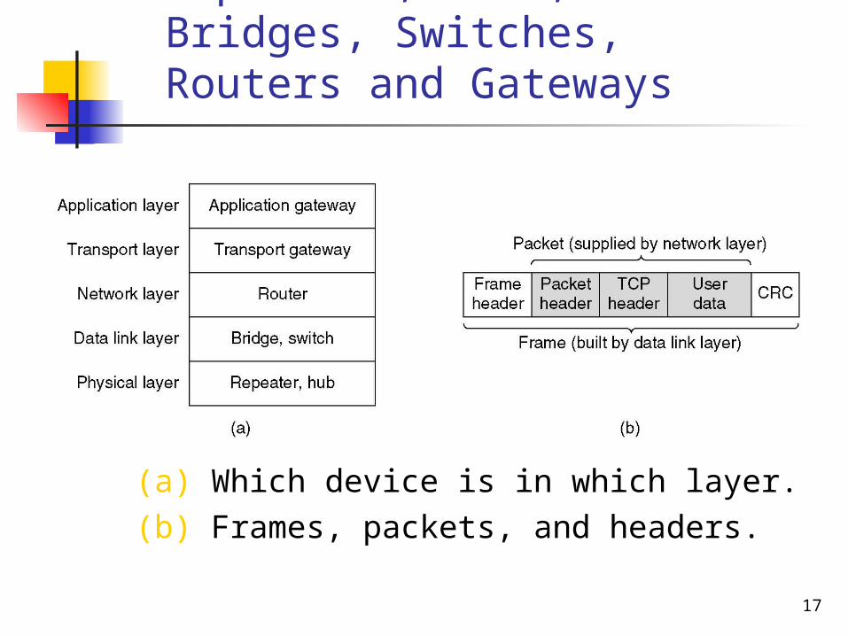
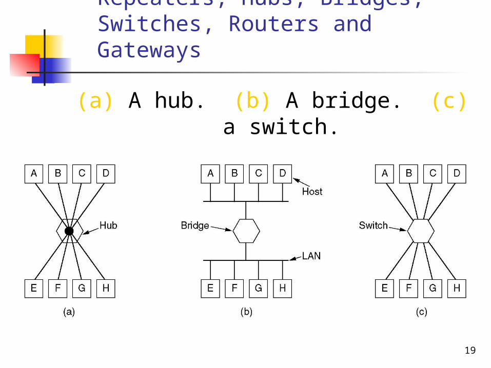
Repeaters, Hubs, Bridges, Switches, Routers and Gateways
(a) Which device is in which layer.(b) Frames, packets, and headers.
18
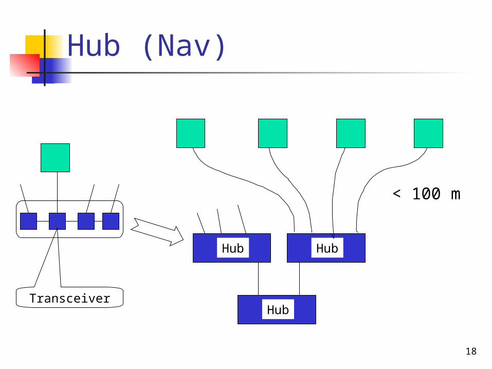
Hub (Nav)
Hub
< 100 m
Hub
HubTransceiver
19
Repeaters, Hubs, Bridges, Switches, Routers and Gateways
(a) A hub. (b) A bridge. (c) a switch.
20
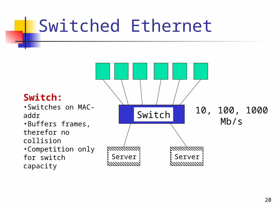
Switched Ethernet
Switch
Server Server
10, 100, 1000Mb/s
Switch:•Switches on MAC-addr•Buffers frames, therefor no collision•Competition only for switch capacity
21
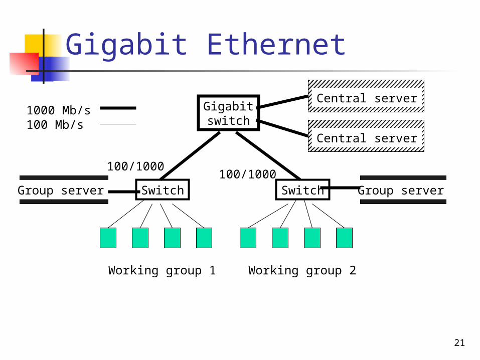
Gigabit Ethernet
Gigabitswitch
Central server
Central server
Switch Switch Group serverGroup server
Working group 1 Working group 2
100/1000100/1000
1000 Mb/s100 Mb/s
22
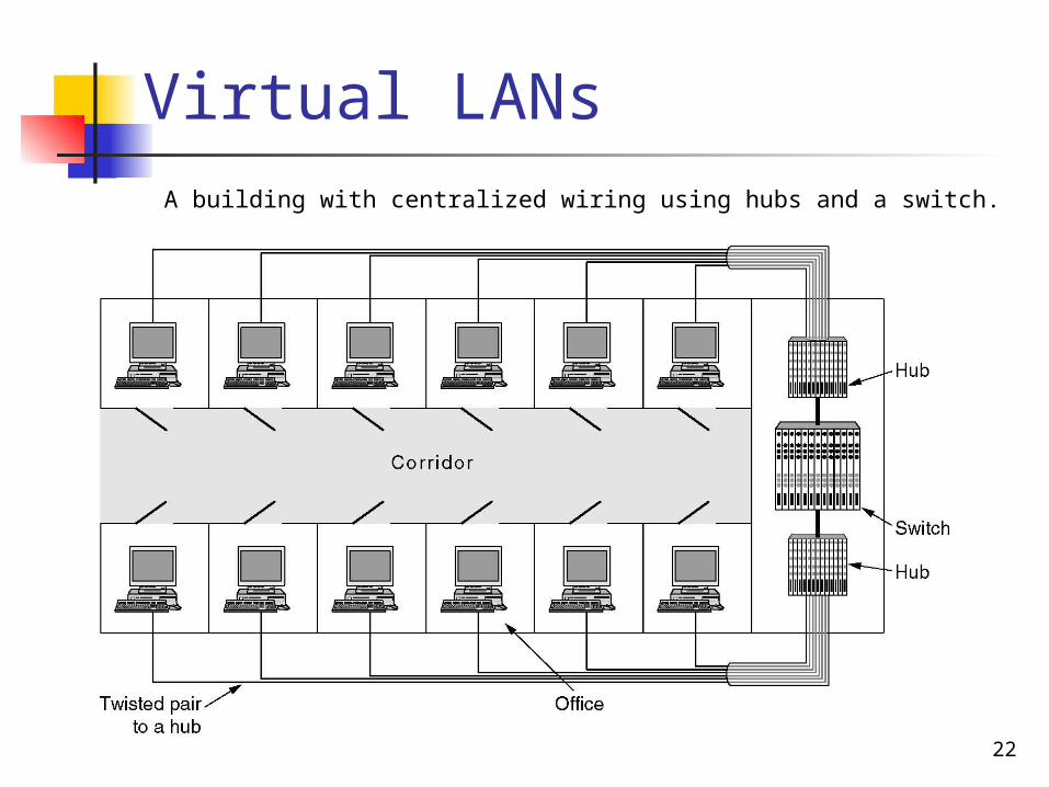
Virtual LANsA building with centralized wiring using hubs and a switch.
23
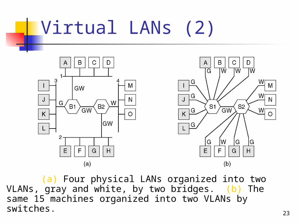
Virtual LANs (2)
(a) Four physical LANs organized into two VLANs, gray and white, by two bridges. (b) The same 15 machines organized into two VLANs by switches.
24
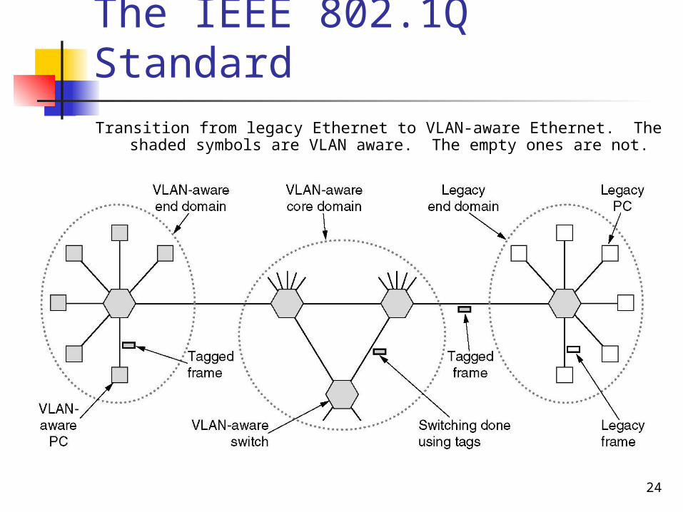
The IEEE 802.1Q StandardTransition from legacy Ethernet to VLAN-aware Ethernet. The
shaded symbols are VLAN aware. The empty ones are not.
25
The IEEE 802.1Q Standard (2)
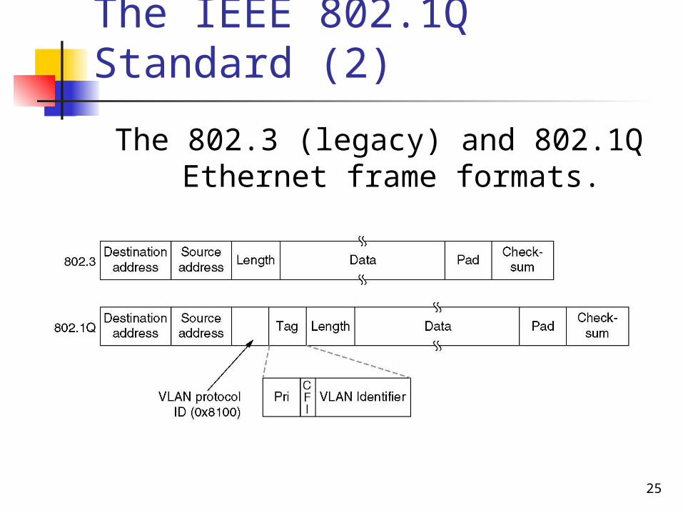
The 802.3 (legacy) and 802.1Q Ethernet frame formats.
26
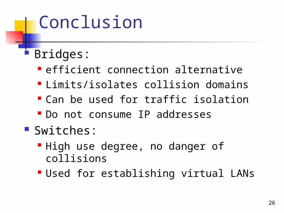
Conclusion
Bridges: efficient connection alternative Limits/isolates collision domains Can be used for traffic isolation Do not consume IP addresses
Switches: High use degree, no danger of
collisions Used for establishing virtual LANs
27
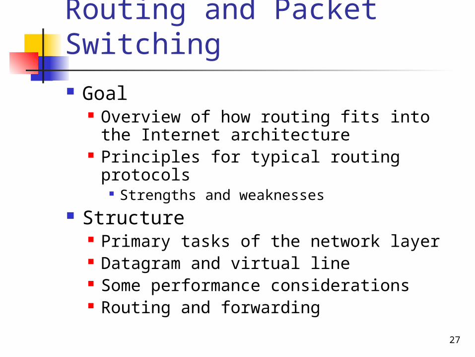
Routing and Packet Switching
Goal Overview of how routing fits into the
Internet architecture Principles for typical routing protocols
Strengths and weaknesses Structure
Primary tasks of the network layer Datagram and virtual line Some performance considerations Routing and forwarding
28
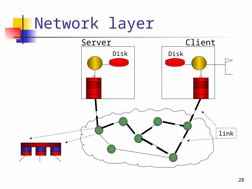
Network layer
DiskDisk
Server Client
link
29
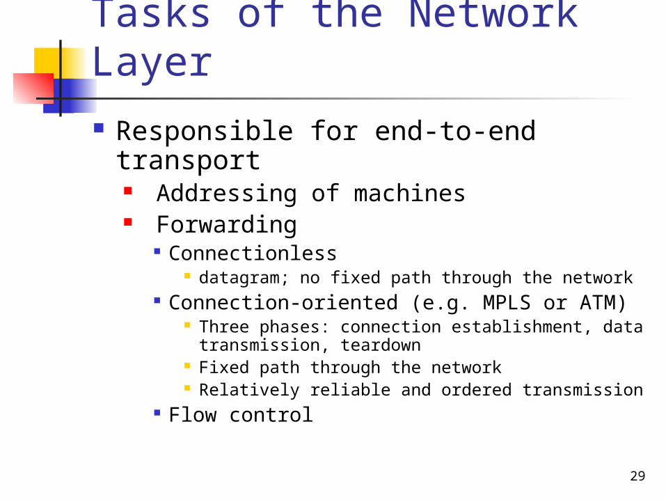
Tasks of the Network Layer
Responsible for end-to-end transport Addressing of machines Forwarding
Connectionless datagram; no fixed path through the network
Connection-oriented (e.g. MPLS or ATM) Three phases: connection establishment, data
transmission, teardown Fixed path through the network Relatively reliable and ordered transmission
Flow control
30
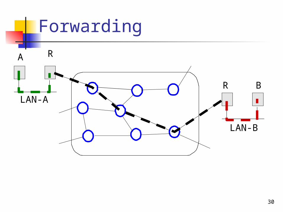
ForwardingR
B
A
R
LAN-A
LAN-B
31
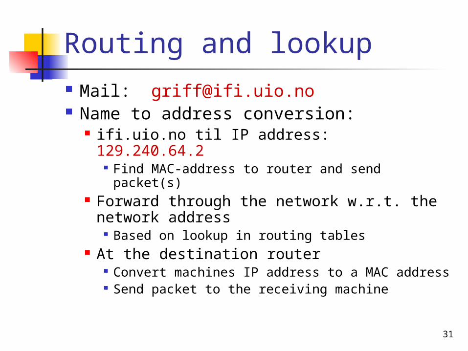
Routing and lookup Mail: [email protected] Name to address conversion:
ifi.uio.no til IP address: 129.240.64.2 Find MAC-address to router and send
packet(s) Forward through the network w.r.t. the
network address Based on lookup in routing tables
At the destination router Convert machines IP address to a MAC
address Send packet to the receiving machine
32
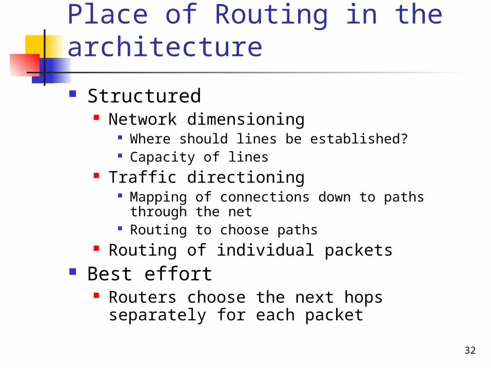
Place of Routing in the architecture
Structured Network dimensioning
Where should lines be established? Capacity of lines
Traffic directioning Mapping of connections down to paths through
the net Routing to choose paths
Routing of individual packets Best effort
Routers choose the next hops separately for each packet
33
Routing
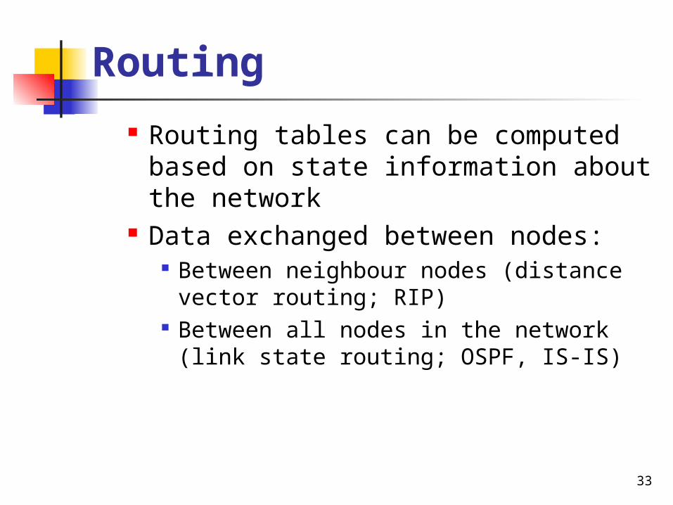
Routing tables can be computed based on state information about the network
Data exchanged between nodes: Between neighbour nodes (distance
vector routing; RIP) Between all nodes in the network (link
state routing; OSPF, IS-IS)
34
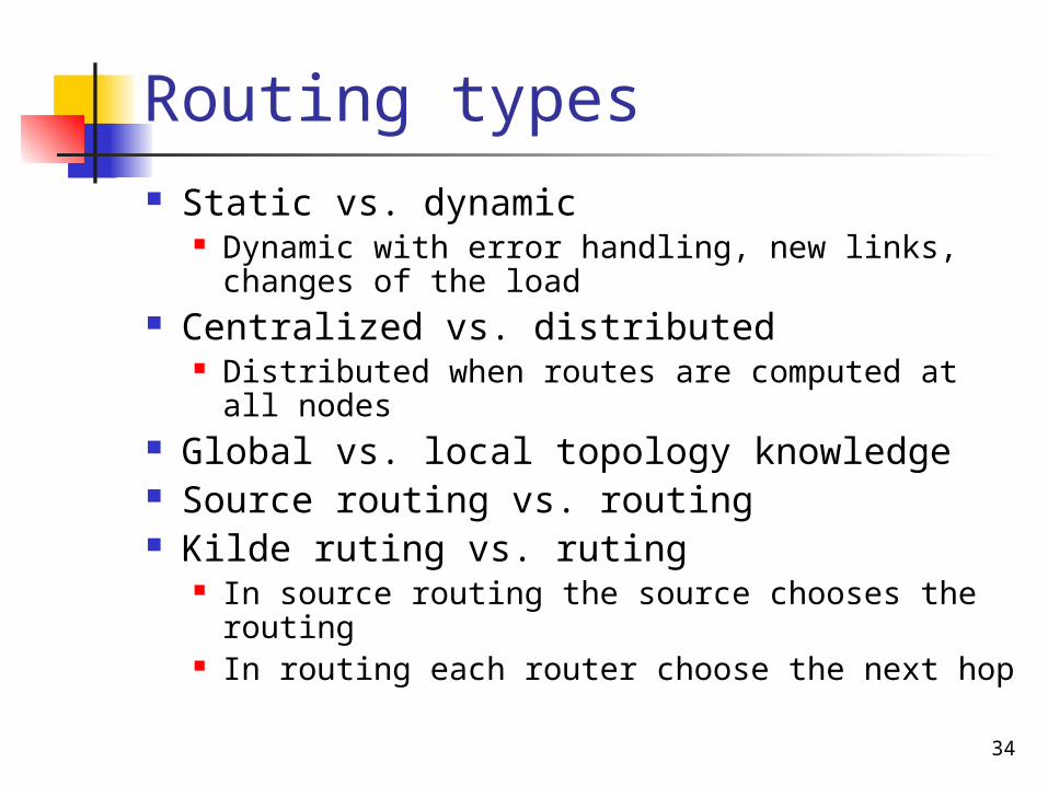
Routing types Static vs. dynamic
Dynamic with error handling, new links, changes of the load
Centralized vs. distributed Distributed when routes are computed at all
nodes Global vs. local topology knowledge Source routing vs. routing Kilde ruting vs. ruting
In source routing the source chooses the routing
In routing each router choose the next hop
35
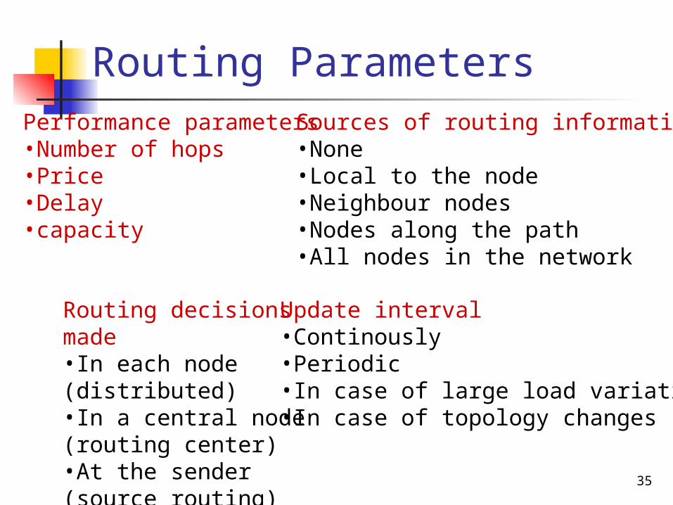
Routing ParametersPerformance parameters•Number of hops•Price•Delay•capacity
Routing decisions made•In each node (distributed)•In a central node (routing center)•At the sender (source routing)
Sources of routing information•None•Local to the node•Neighbour nodes•Nodes along the path•All nodes in the network
Update interval•Continously•Periodic•In case of large load variations•In case of topology changes
36
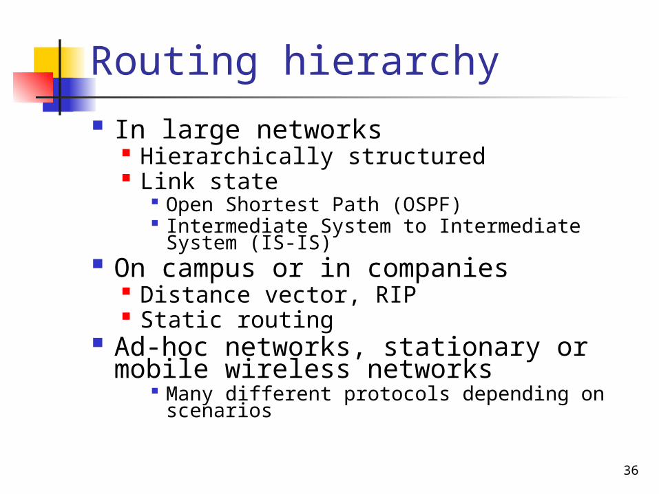
Routing hierarchy In large networks
Hierarchically structured Link state
Open Shortest Path (OSPF) Intermediate System to Intermediate System
(IS-IS) On campus or in companies
Distance vector, RIP Static routing
Ad-hoc networks, stationary or mobile wireless networks
Many different protocols depending on scenarios
37
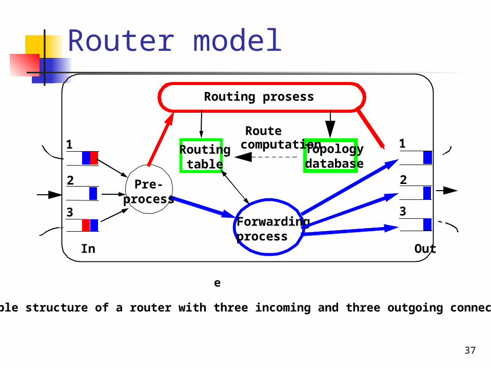
Router model
Forwardingprocess
Pre-process
In
1
2
3
1
2
3
Out
e
Principle structure of a router with three incoming and three outgoing connections
Routingtable
Topologydatabase
Routing prosess
Routecomputation
38
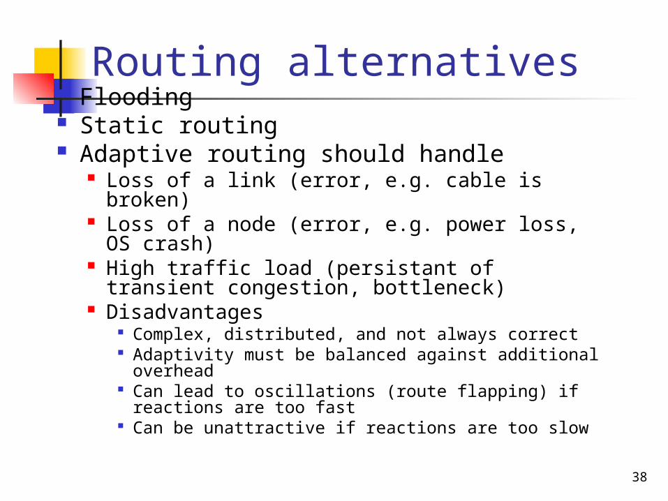
Routing alternatives Flooding Static routing Adaptive routing should handle
Loss of a link (error, e.g. cable is broken) Loss of a node (error, e.g. power loss, OS
crash) High traffic load (persistant of transient
congestion, bottleneck) Disadvantages
Complex, distributed, and not always correct Adaptivity must be balanced against additional
overhead Can lead to oscillations (route flapping) if
reactions are too fast Can be unattractive if reactions are too slow
39
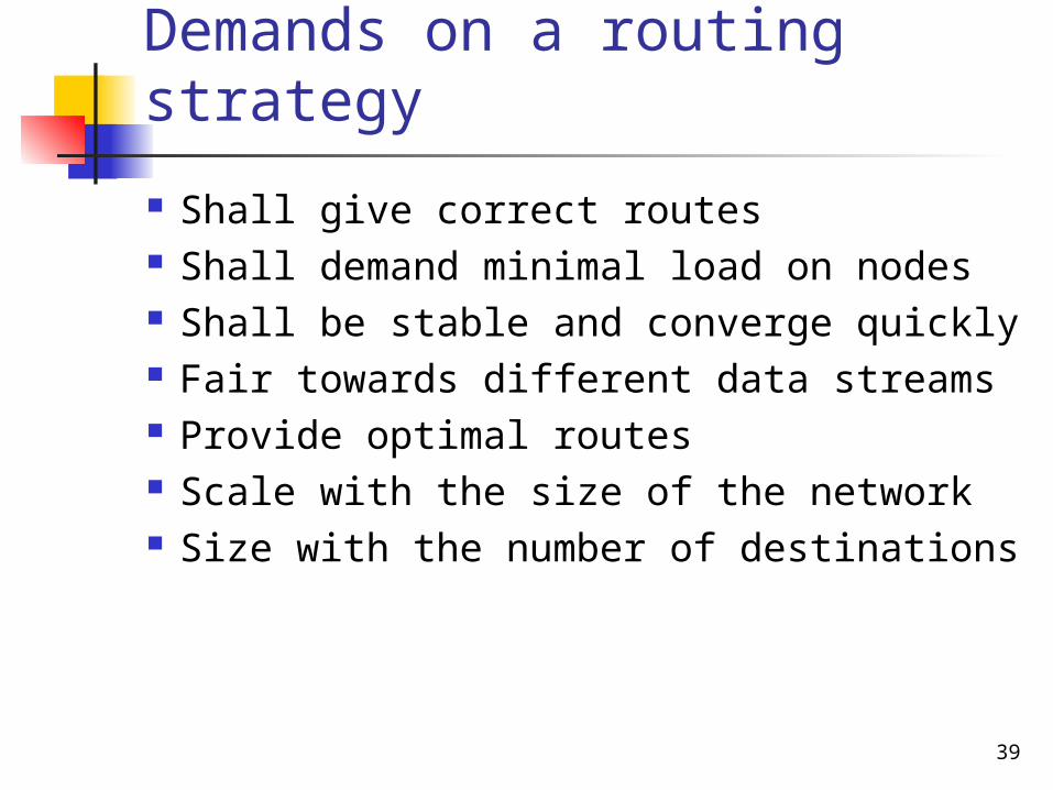
Demands on a routing strategy
Shall give correct routes Shall demand minimal load on nodes Shall be stable and converge quickly Fair towards different data streams Provide optimal routes Scale with the size of the network Size with the number of destinations
40
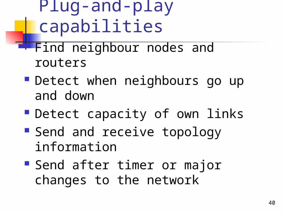
Plug-and-play capabilities Find neighbour nodes and routers Detect when neighbours go up and
down Detect capacity of own links Send and receive topology
information Send after timer or major changes
to the network
41
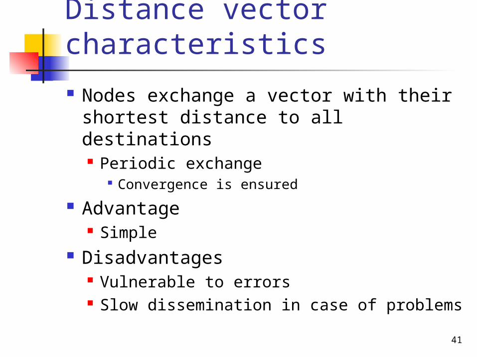
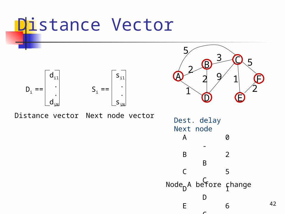
Distance vector characteristics
Nodes exchange a vector with their shortest distance to all destinations Periodic exchange
Convergence is ensured
Advantage Simple
Disadvantages Vulnerable to errors Slow dissemination in case of problems
42
Distance Vector
AB C
D E
F1
2
5
22
9 1di1
. .diN
Di ==
si1
. .siN
Si ==
Distance vector Next node vectorDest. delay Next node A 0
- B 2 B C 5 C D 1
D E 6 C F 8 CNode A before change
53

44
Router model
Forwardingprocess
Pre-process
In
1
2
3
1
2
3
Out
e
Principle structure of a router with three incoming and three outgoing connections
Routingtable
Topologydatabase
Routing prosess
Routecomputation
45
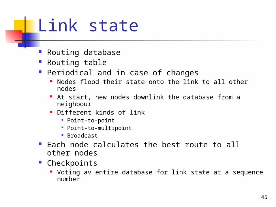
Link state Routing database Routing table Periodical and in case of changes
Nodes flood their state onto the link to all other nodes At start, new nodes downlink the database from a
neighbour Different kinds of link
Point-to-point Point-to-multipoint Broadcast
Each node calculates the best route to all other nodes
Checkpoints Voting av entire database for link state at a sequence
number
46
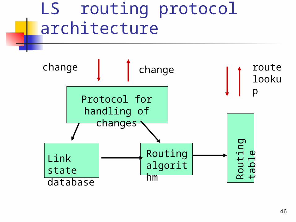
LS routing protocol architecture
changechange
Protocol for handling of changes
Link state database
Routing algorithm
Rou
ting
tabl
e
route lookup
47
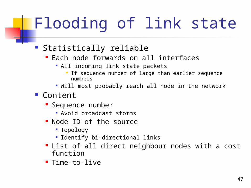
Flooding of link state Statistically reliable
Each node forwards on all interfaces All incoming link state packets
If sequence number of large than earlier sequence numbers Will most probably reach all node in the network
Content Sequence number
Avoid broadcast storms Node ID of the source
Topology Identify bi-directional links
List of all direct neighbour nodes with a cost function
Time-to-live
48
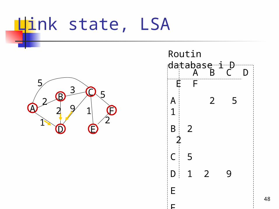
Link state, LSA
AB C
D E
F1
2
5
22
9 1
53
A B C D E F
A 2 5 1
B 2 2
C 5
D 1 2 9
E
F
Routin database i D
49
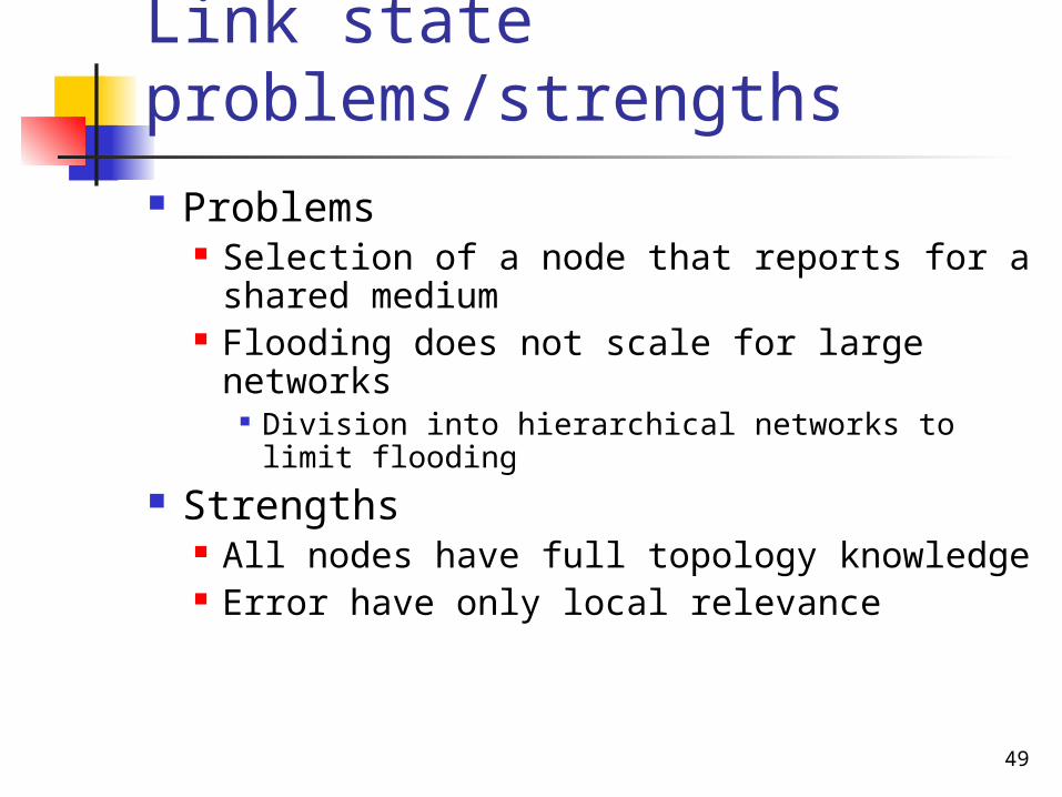
Link state problems/strengths Problems
Selection of a node that reports for a shared medium
Flooding does not scale for large networks
Division into hierarchical networks to limit flooding
Strengths All nodes have full topology knowledge Error have only local relevance
50
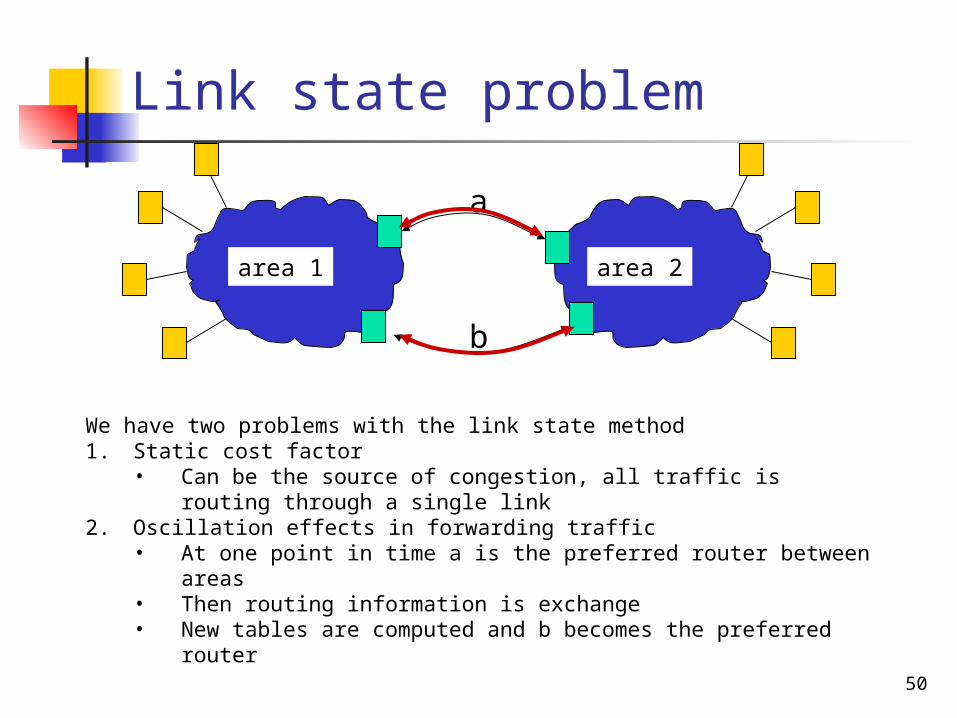
Link state problem
area 1 area 2
a
b
We have two problems with the link state method1. Static cost factor
• Can be the source of congestion, all traffic is routing through a single link2. Oscillation effects in forwarding traffic
• At one point in time a is the preferred router between areas• Then routing information is exchange• New tables are computed and b becomes the preferred router
51
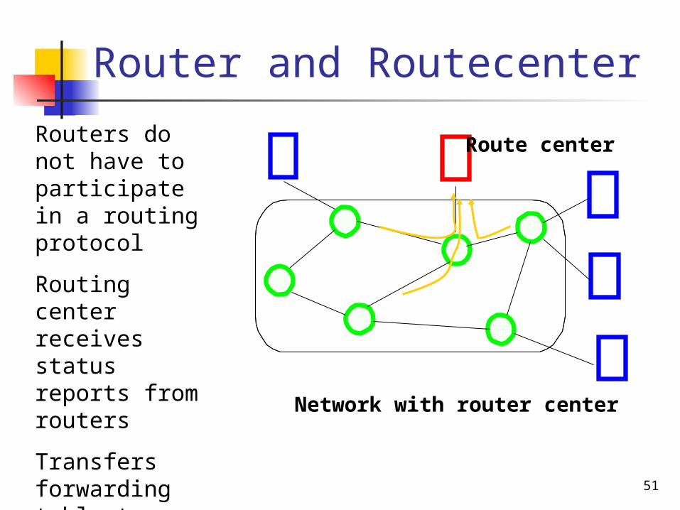
Router and Routecenter
Network with router center
Route centerRouters do not have to participate in a routing protocol
Routing center receives status reports from routers
Transfers forwarding table to routers
52
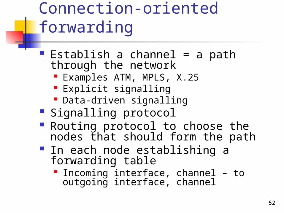
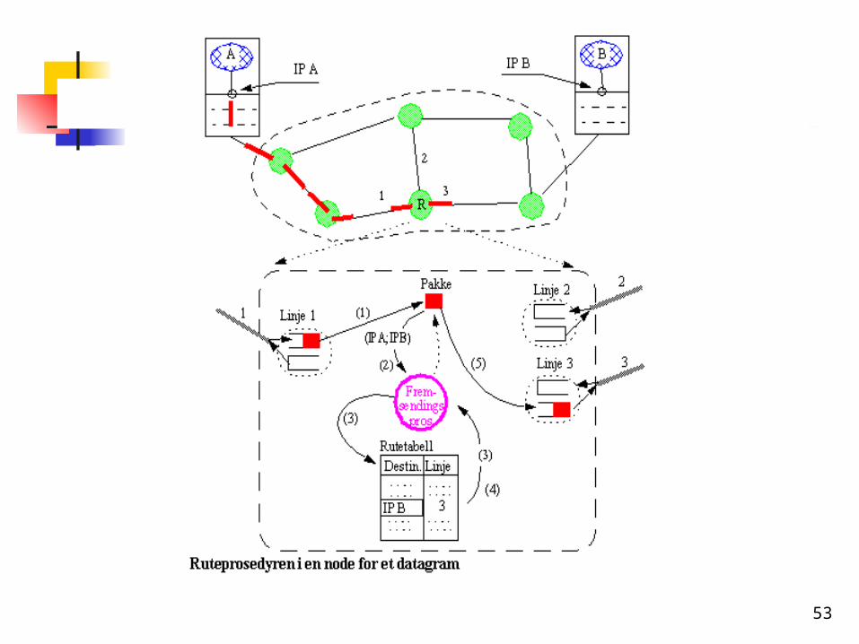
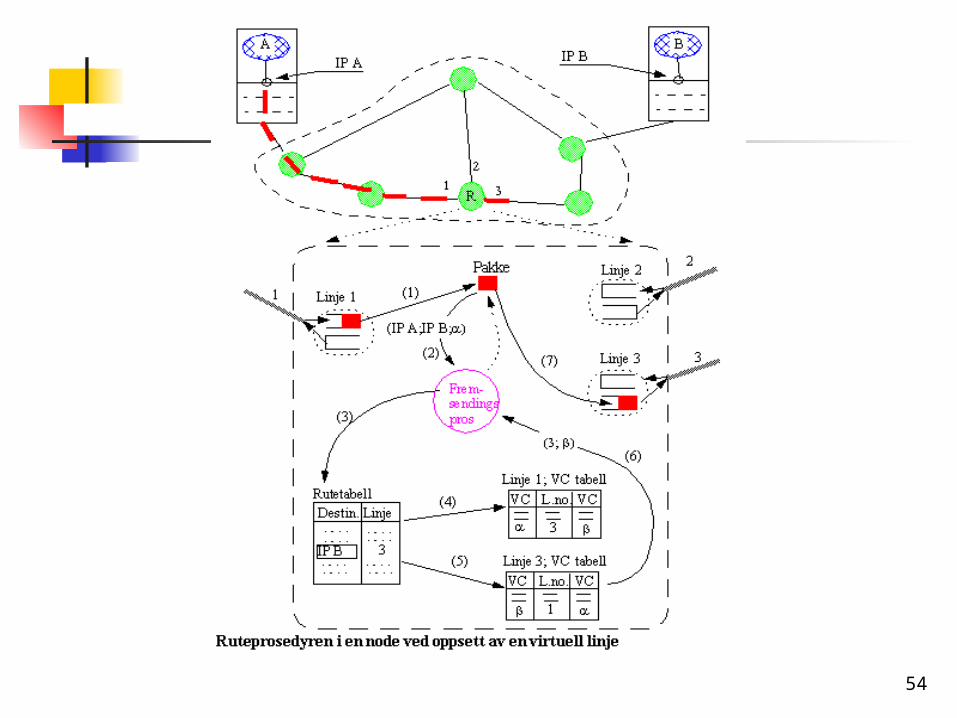
Connection-oriented forwarding Establish a channel = a path through
the network Examples ATM, MPLS, X.25 Explicit signalling Data-driven signalling
Signalling protocol Routing protocol to choose the nodes
that should form the path In each node establishing a forwarding
table Incoming interface, channel – to outgoing
interface, channel
53
54
55
node x node y
C
1
1 2
V.C. tables
12
34
1 2
1
2 2a
b
c
b
V.C. tables
c
DA
B
a1 ; c ; 32 ; c ; 4
b1 ; c ; 22 ; c ; 1
1 ; b ; 22 ; b ; 13 ; a ; 14 ; a ; 2
c1 ; a; 32 ; a; 4
1 ; a; 12 ; a; 2
1 ; b ; 12 ; b ; 23 ; c ; 14 ; c ; 2
cba
a
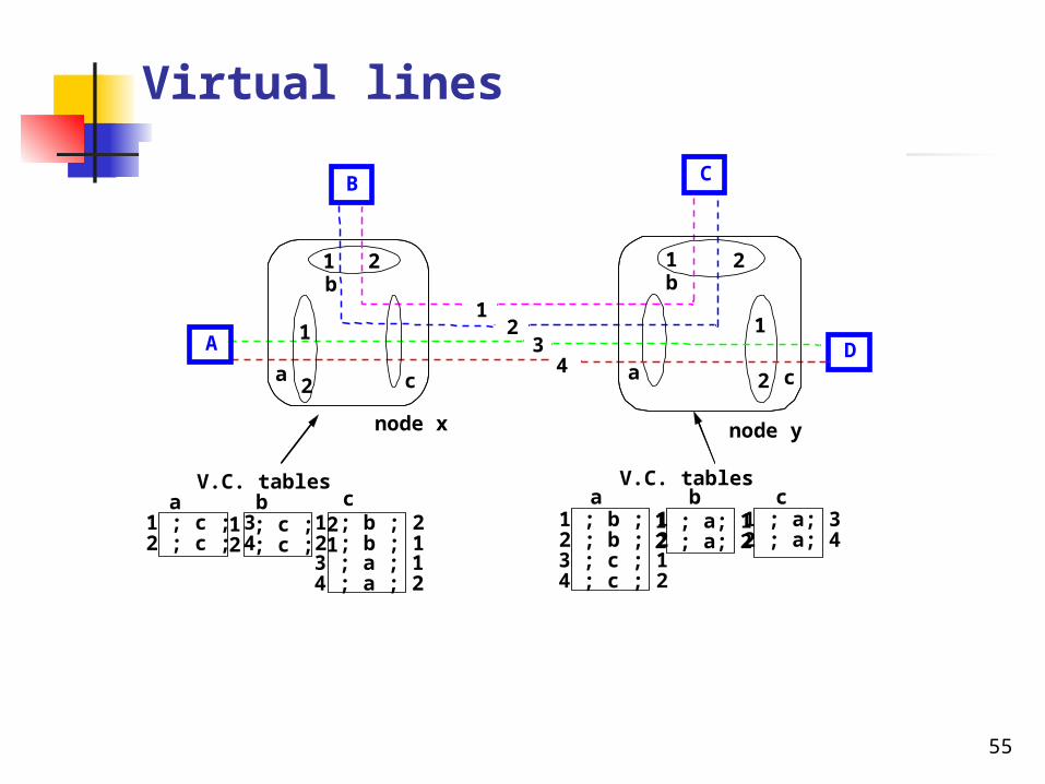
Virtual lines
56
Dynamic cost in route computation
Adaptation of routes to load Move traffic to lines with lower load
Main problem Delay between measurement and computation Delay between route computation and traffic
arrival Fast variation in load
Bad predictability
Route flapping (oscillations) Overhead of exchanging the routing
information
57
Performance of the network
Performance of the networks means capacity, delay, delay variation (jitter), and reliable
Has several elements Transmission delay
Sending delay Signal propagiation time
Node delay Processing time Queueing time
58
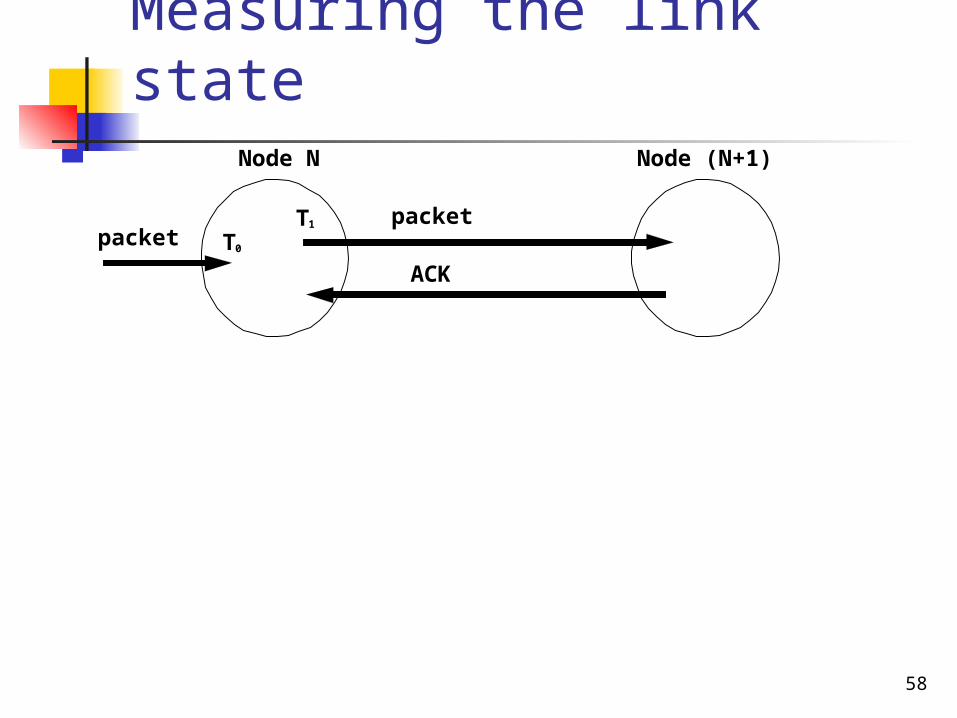
Measuring the link stateNode N Node (N+1)
T0
T1
packetpacket
ACK
59
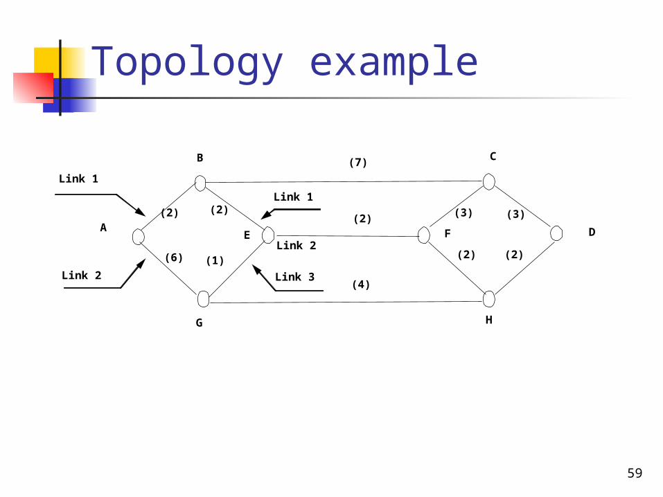
Topology example
(2)A
B C
DFE
G H
(7)
(2)(2)
(1)(6)
(4)
(2)
(3)(3)
(2)
Link 1
Link 2
Link 1
Link 2
Link 3
60
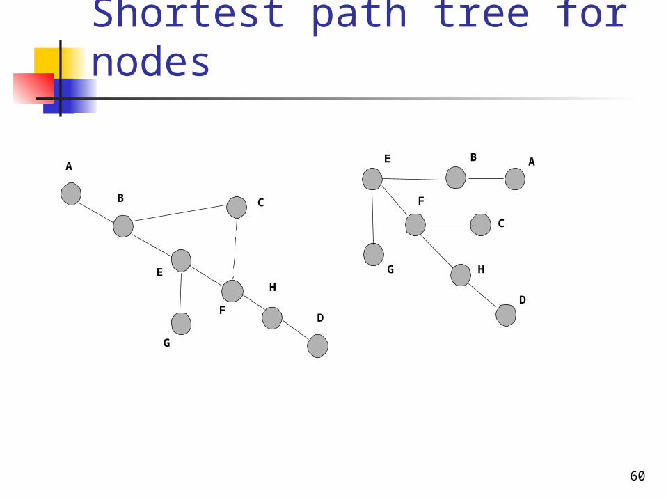
Shortest path tree for nodes
A
B
E
G
F
C
H
D
E B A
C
F
H
D
G
61
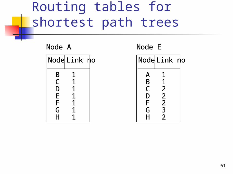
Routing tables for shortest path trees
Node A
Node Link no
1111111
BCDEFGH
Node E
Node Link no
1122232
ABCDFGH
62
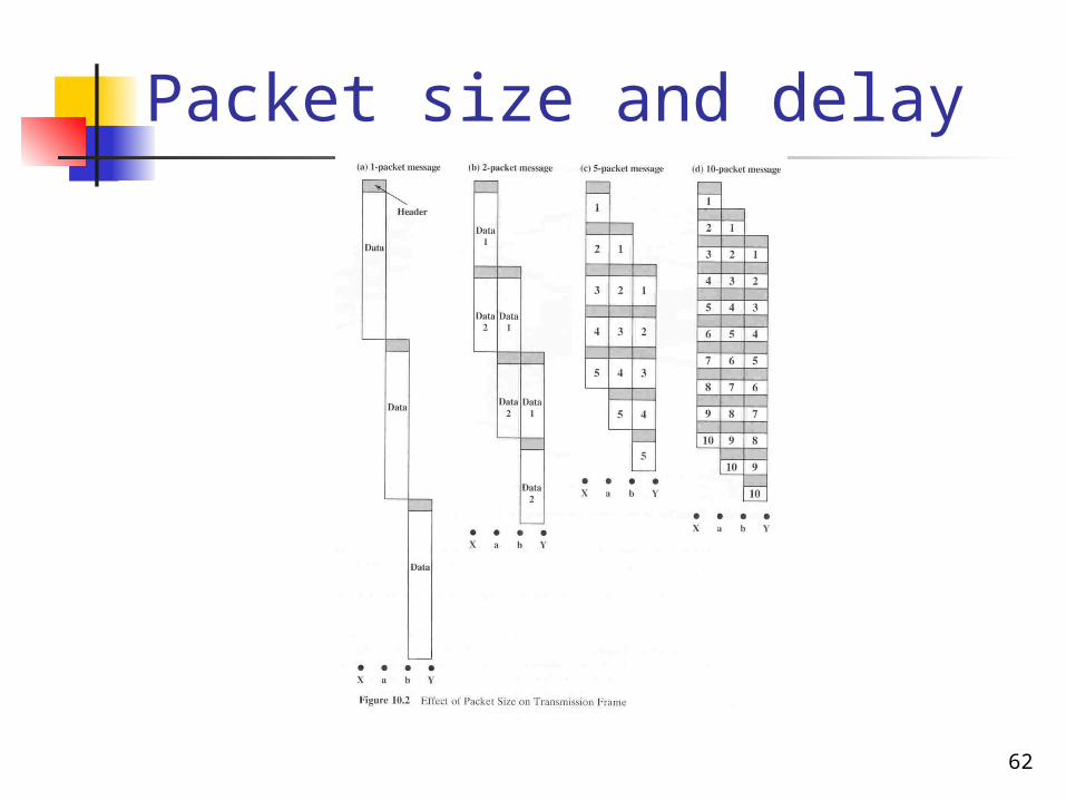
Packet size and delay
63
Modified load variation
1
2
3
4
5
Kost
0,51,0
Utnyttelsesgrad
Jordbunden
Satellitt
Køteoretiskforsinkelse
64
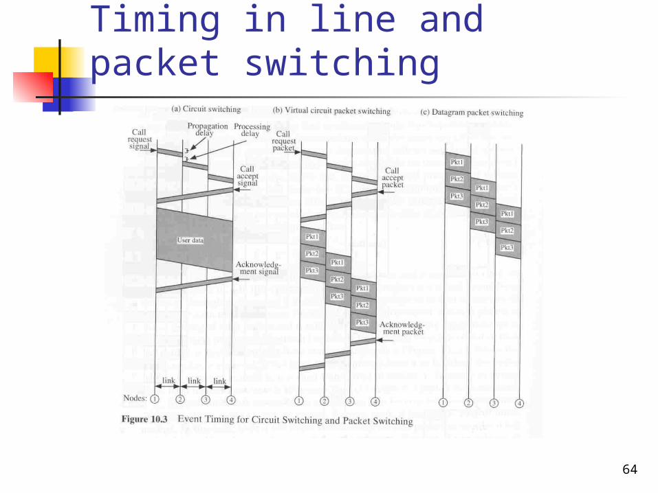
Timing in line and packet switching