Embed Size (px)
Citation preview
1 L Rotary Vacuum Evaporator
Instruction Manual
This manual is designed for safe and optimal performance of this unit
Please read manual carefully before operating this unit
Important
Keep this manual near the unit
1
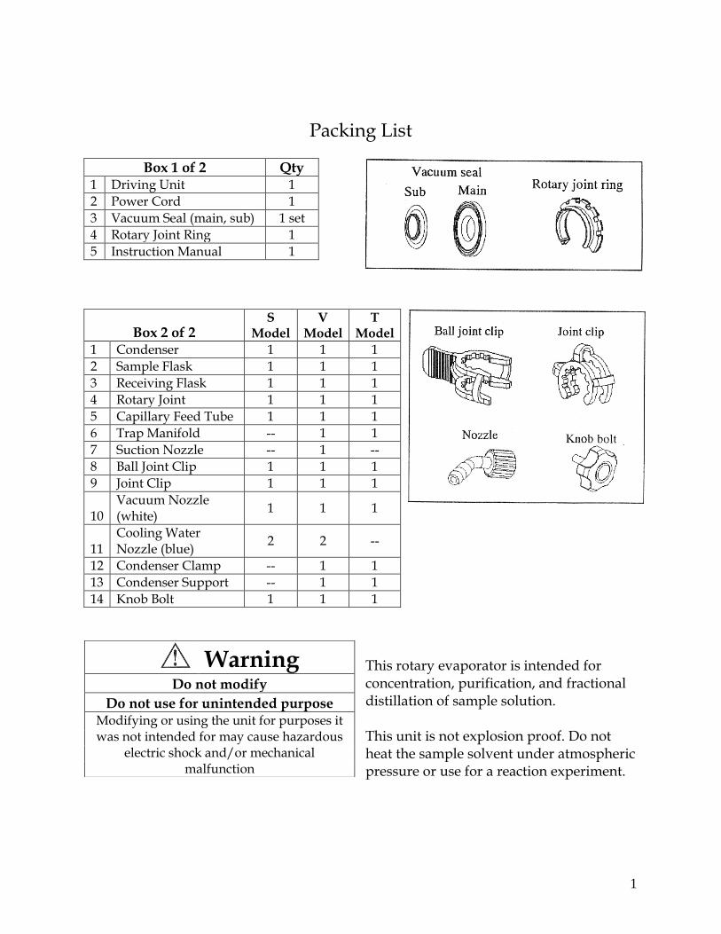
Packing List
Box 1 of 2 Qty 1 Driving Unit 1
2 Power Cord 1
3 Vacuum Seal (main, sub) 1 set
4 Rotary Joint Ring 1
5 Instruction Manual 1
Box 2 of 2 S
Model V
Model T
Model
1 Condenser 1 1 1
2 Sample Flask 1 1 1
3 Receiving Flask 1 1 1
4 Rotary Joint 1 1 1
5 Capillary Feed Tube 1 1 1
6 Trap Manifold -- 1 1
7 Suction Nozzle -- 1 --
8 Ball Joint Clip 1 1 1
9 Joint Clip 1 1 1
10 Vacuum Nozzle (white)
1 1 1
11 Cooling Water Nozzle (blue)
2 2 --
12 Condenser Clamp -- 1 1
13 Condenser Support -- 1 1
14 Knob Bolt 1 1 1
This rotary evaporator is intended for concentration, purification, and fractional distillation of sample solution. This unit is not explosion proof. Do not heat the sample solvent under atmospheric pressure or use for a reaction experiment.
Warning Do not modify
Do not use for unintended purpose Modifying or using the unit for purposes it was not intended for may cause hazardous
electric shock and/or mechanical malfunction
2
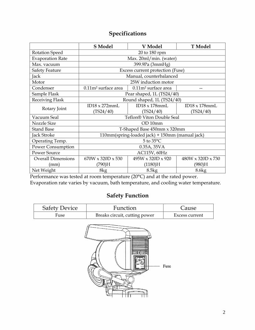
Specifications
S Model V Model T Model Rotation Speed 20 to 180 rpm
Evaporation Rate Max. 20ml/min. (water)
Max. vacuum 399.9Pa (3mmHg)
Safety Feature Excess current protection (Fuse)
Jack Manual, counterbalanced
Motor 25W induction motor
Condenser 0.11m² surface area 0.11m² surface area --
Sample Flask Pear shaped, 1L (TS24/40)
Receiving Flask Round shaped, 1L (TS24/40)
Rotary Joint ID18 x 272mmL
(TS24/40) ID18 x 178mmL
(TS24/40) ID18 x 178mmL
(TS24/40)
Vacuum Seal Teflon® Viton Double Seal
Nozzle Size OD 10mm
Stand Base T-Shaped Base 450mm x 320mm
Jack Stroke 110mm(spring-loaded jack) + 150mm (manual jack)
Operating Temp. 5 to 35°C
Power Consumption 0.35A, 35VA
Power Source AC115V, 60Hz
Overall Dimensions (mm)
670W x 320D x 530 (790)H
495W x 320D x 920 (1180)H
480W x 320D x 730 (980)H
Net Weight 8kg 8.5kg 8.6kg
Performance was tested at room temperature (20°C) and at the rated power. Evaporation rate varies by vacuum, bath temperature, and cooling water temperature.
Safety Function
Safety Device Function Cause Fuse Breaks circuit, cutting power Excess current
3
Warning For installation, choose a surface that is: flat; free of any flammable solids, liquids and gases; between 5 and 35°C; less than 85% relative humidity; free of dust; not exposed to direct sunlight; away from any heat sources; and well ventilated.
Do not install in a hazardous atmosphere
This product is not explosion proof. Use of this product in a dangerous atmosphere may cause a fire or explosion
Warning Warning Use recommended voltage, phase,
and capacity. Do not use a multi-plug extension cord. Using a multi-plug extension cord may expose
the unit to excess current and cause a fire Using an unsuitable power source may cause a fire or electrical shock hazard
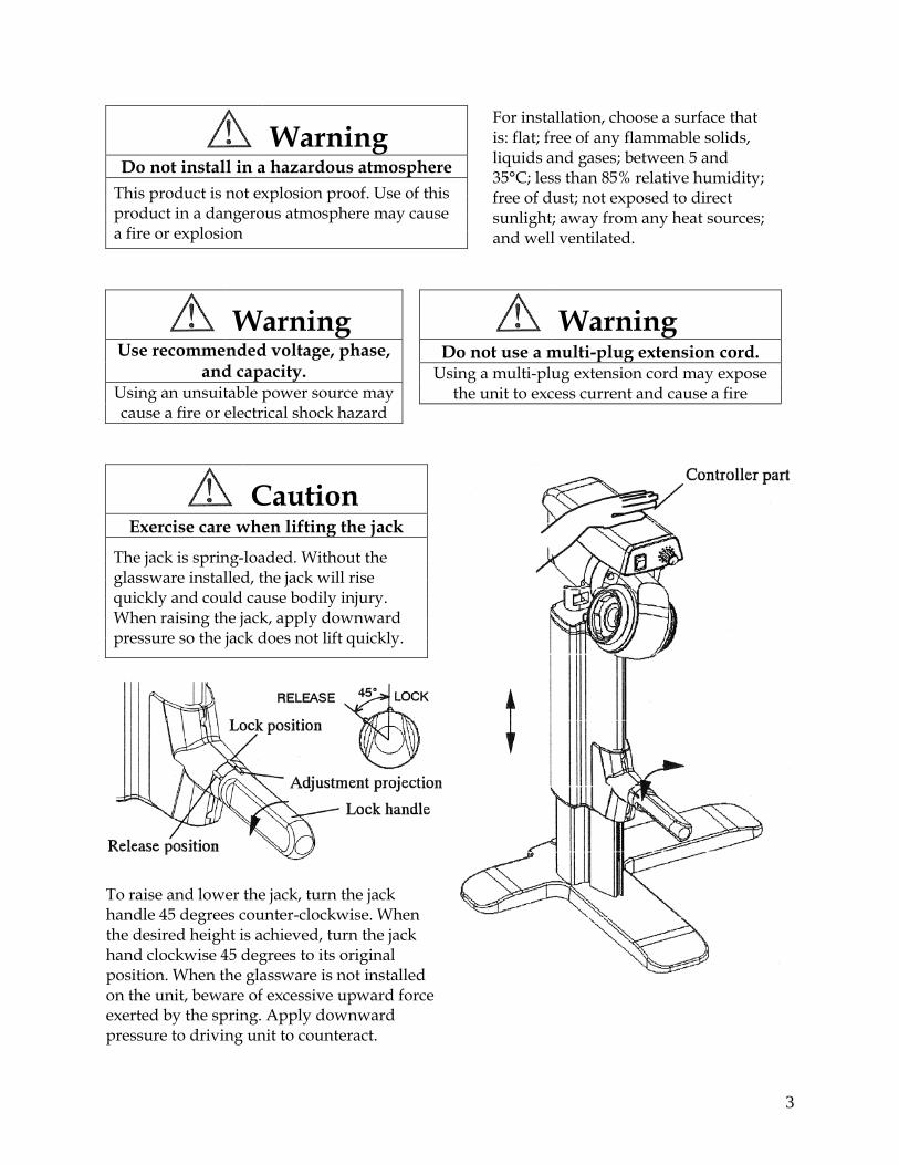
Caution Exercise care when lifting the jack
The jack is spring-loaded. Without the glassware installed, the jack will rise quickly and could cause bodily injury. When raising the jack, apply downward pressure so the jack does not lift quickly.
To raise and lower the jack, turn the jack handle 45 degrees counter-clockwise. When the desired height is achieved, turn the jack hand clockwise 45 degrees to its original position. When the glassware is not installed on the unit, beware of excessive upward force exerted by the spring. Apply downward pressure to driving unit to counteract.
4
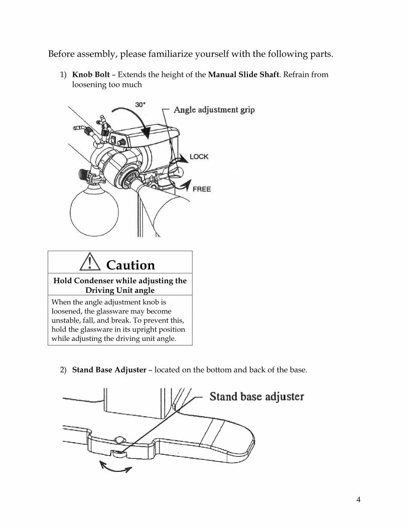
Before assembly, please familiarize yourself with the following parts.
1) Knob Bolt – Extends the height of the Manual Slide Shaft. Refrain from loosening too much
Caution Hold Condenser while adjusting the
Driving Unit angle
When the angle adjustment knob is loosened, the glassware may become unstable, fall, and break. To prevent this, hold the glassware in its upright position while adjusting the driving unit angle.
2) Stand Base Adjuster – located on the bottom and back of the base.
5
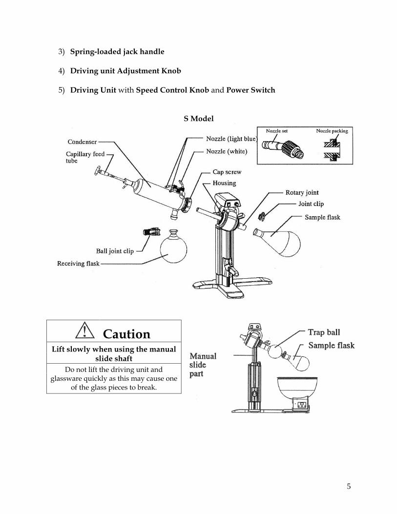
3) Spring-loaded jack handle 4) Driving unit Adjustment Knob 5) Driving Unit with Speed Control Knob and Power Switch
S Model
Caution Lift slowly when using the manual
slide shaft
Do not lift the driving unit and glassware quickly as this may cause one
of the glass pieces to break.
6
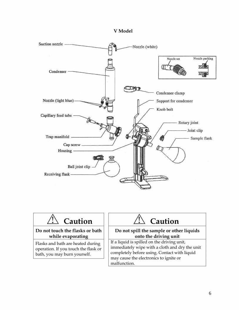
V Model
Caution Caution Do not touch the flasks or bath
while evaporating
Do not spill the sample or other liquids onto the driving unit
Flasks and bath are heated during operation. If you touch the flask or bath, you may burn yourself.
If a liquid is spilled on the driving unit, immediately wipe with a cloth and dry the unit completely before using. Contact with liquid may cause the electronics to ignite or malfunction.
7
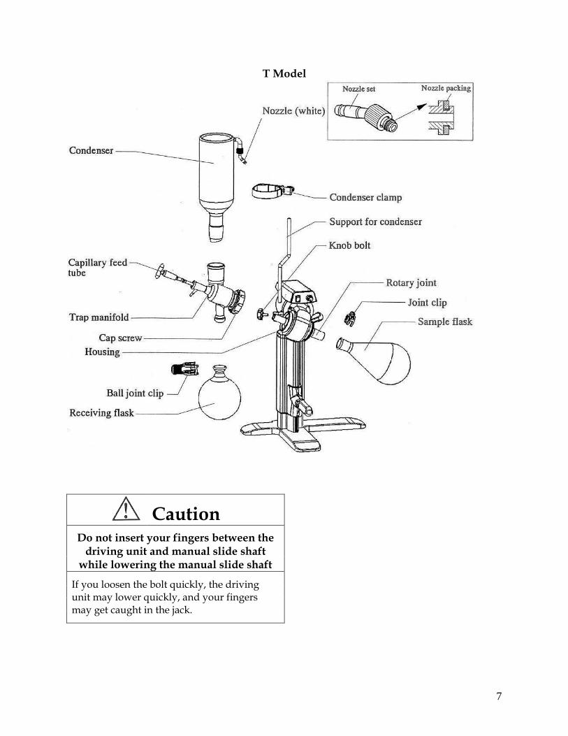
T Model
Caution Do not insert your fingers between the
driving unit and manual slide shaft while lowering the manual slide shaft
If you loosen the bolt quickly, the driving unit may lower quickly, and your fingers may get caught in the jack.
8
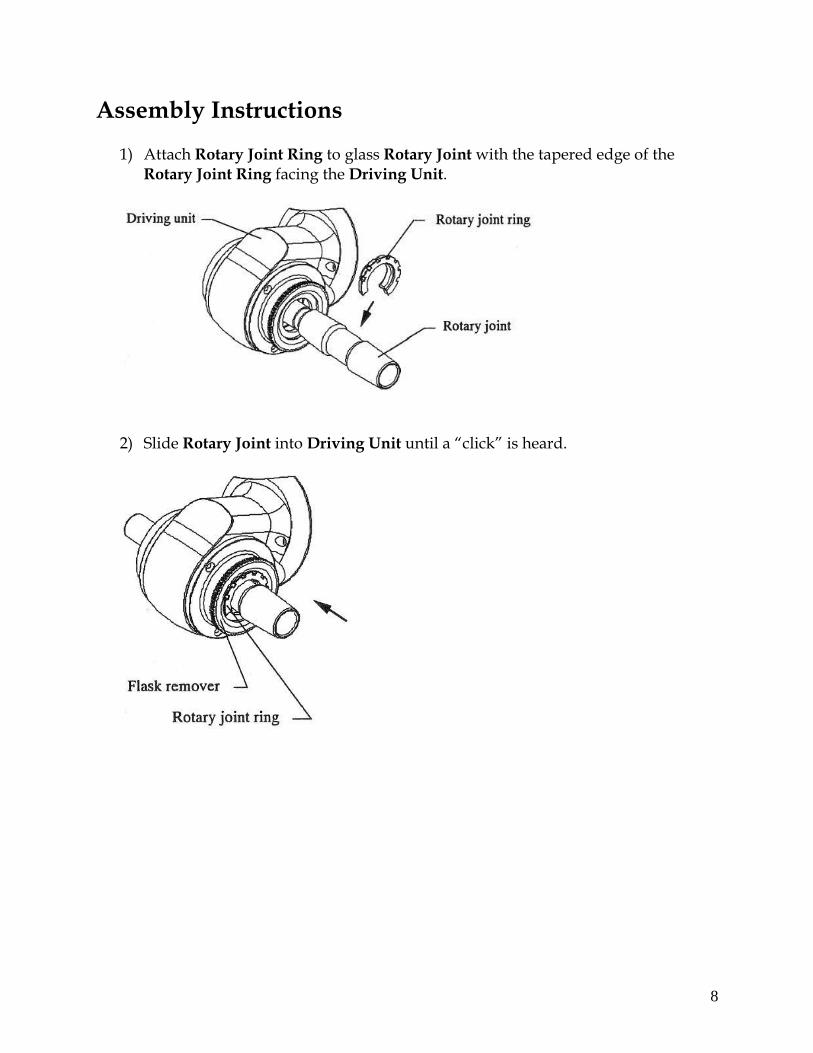
Assembly Instructions
1) Attach Rotary Joint Ring to glass Rotary Joint with the tapered edge of the Rotary Joint Ring facing the Driving Unit.
2) Slide Rotary Joint into Driving Unit until a “click” is heard.
9
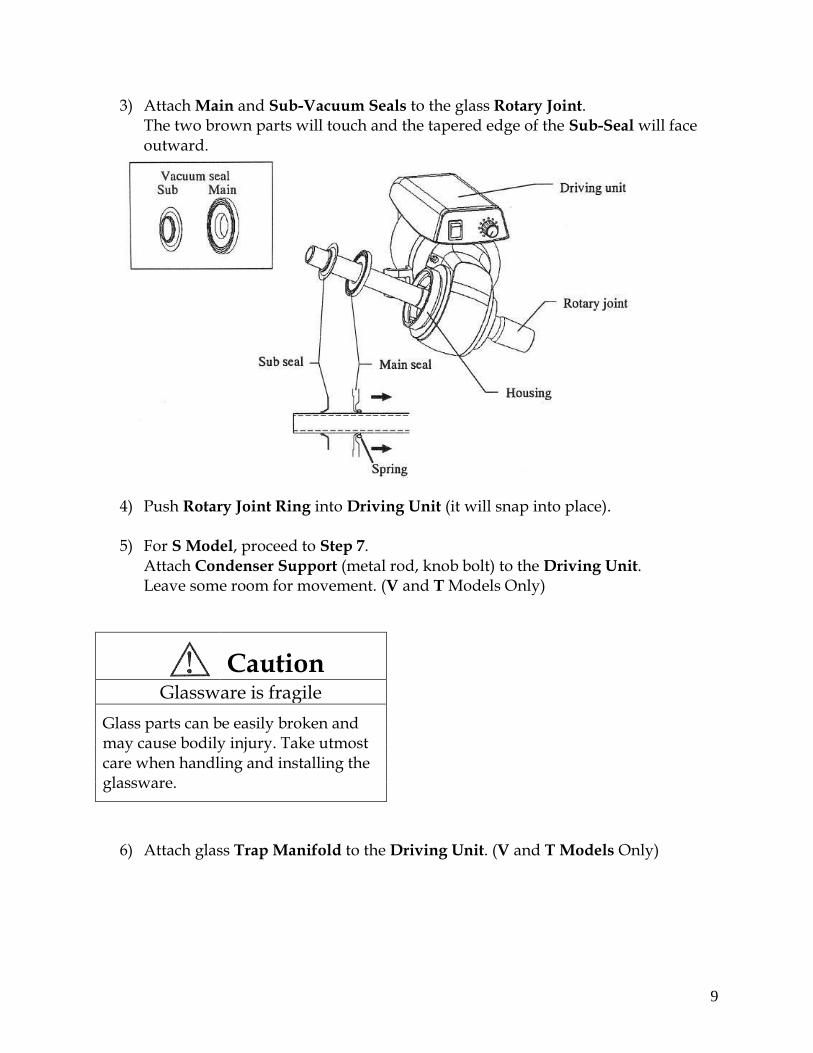
3) Attach Main and Sub-Vacuum Seals to the glass Rotary Joint. The two brown parts will touch and the tapered edge of the Sub-Seal will face outward.
4) Push Rotary Joint Ring into Driving Unit (it will snap into place). 5) For S Model, proceed to Step 7.
Attach Condenser Support (metal rod, knob bolt) to the Driving Unit. Leave some room for movement. (V and T Models Only)
Caution Glassware is fragile
Glass parts can be easily broken and may cause bodily injury. Take utmost care when handling and installing the glassware.
6) Attach glass Trap Manifold to the Driving Unit. (V and T Models Only)
10
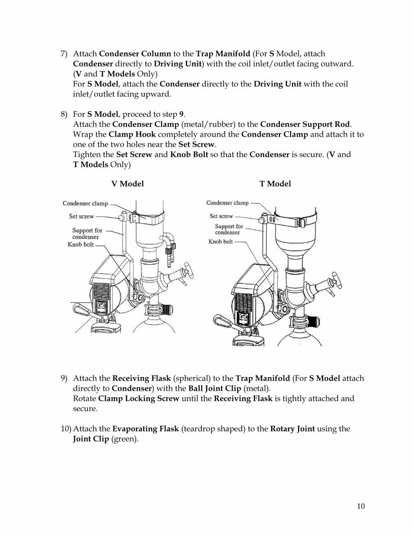
7) Attach Condenser Column to the Trap Manifold (For S Model, attach Condenser directly to Driving Unit) with the coil inlet/outlet facing outward. (V and T Models Only) For S Model, attach the Condenser directly to the Driving Unit with the coil inlet/outlet facing upward.
8) For S Model, proceed to step 9. Attach the Condenser Clamp (metal/rubber) to the Condenser Support Rod. Wrap the Clamp Hook completely around the Condenser Clamp and attach it to one of the two holes near the Set Screw. Tighten the Set Screw and Knob Bolt so that the Condenser is secure. (V and T Models Only)
V Model
T Model
9) Attach the Receiving Flask (spherical) to the Trap Manifold (For S Model attach directly to Condenser) with the Ball Joint Clip (metal). Rotate Clamp Locking Screw until the Receiving Flask is tightly attached and secure.
10) Attach the Evaporating Flask (teardrop shaped) to the Rotary Joint using the
Joint Clip (green).
11
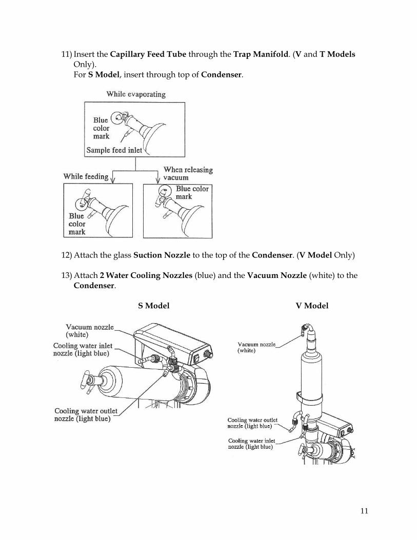
11) Insert the Capillary Feed Tube through the Trap Manifold. (V and T Models Only). For S Model, insert through top of Condenser.
12) Attach the glass Suction Nozzle to the top of the Condenser. (V Model Only) 13) Attach 2 Water Cooling Nozzles (blue) and the Vacuum Nozzle (white) to the
Condenser.
S Model V Model
12
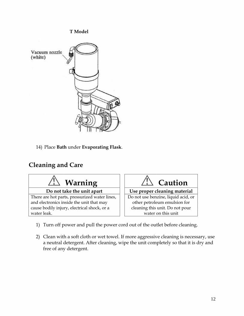
T Model
14) Place Bath under Evaporating Flask.
Cleaning and Care
Warning Caution Do not take the unit apart Use proper cleaning material
There are hot parts, pressurized water lines, and electronics inside the unit that may cause bodily injury, electrical shock, or a water leak.
Do not use benzine, liquid acid, or other petroleum emulsion for cleaning this unit. Do not pour
water on this unit
1) Turn off power and pull the power cord out of the outlet before cleaning.
2) Clean with a soft cloth or wet towel. If more aggressive cleaning is necessary, use a neutral detergent. After cleaning, wipe the unit completely so that it is dry and free of any detergent.
13
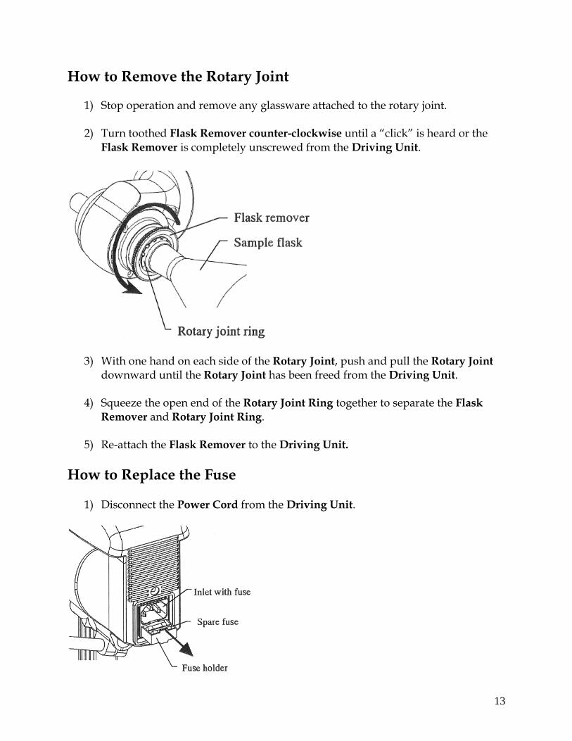
How to Remove the Rotary Joint
1) Stop operation and remove any glassware attached to the rotary joint.
2) Turn toothed Flask Remover counter-clockwise until a “click” is heard or the Flask Remover is completely unscrewed from the Driving Unit.
3) With one hand on each side of the Rotary Joint, push and pull the Rotary Joint downward until the Rotary Joint has been freed from the Driving Unit.
4) Squeeze the open end of the Rotary Joint Ring together to separate the Flask
Remover and Rotary Joint Ring.
5) Re-attach the Flask Remover to the Driving Unit.
How to Replace the Fuse
1) Disconnect the Power Cord from the Driving Unit.
14
2) Remove the Fuse Cartridge using a flat-head screw driver. The inner-most fuse is the main fuse and the outer-most fuse is the spare.
3) Remove the Main Fuse and replace it with the Spare Fuse.
Fuse Specs: 115V, 630mA Cat. No. 142720
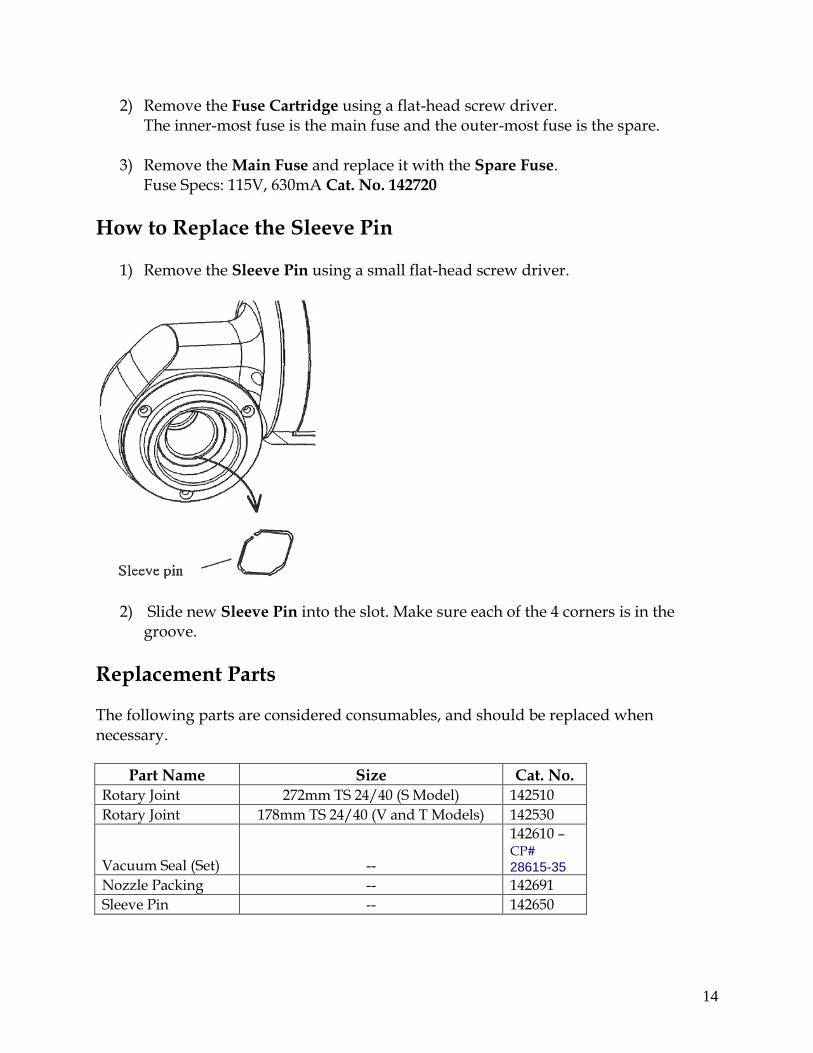
How to Replace the Sleeve Pin
1) Remove the Sleeve Pin using a small flat-head screw driver.
2) Slide new Sleeve Pin into the slot. Make sure each of the 4 corners is in the groove.
Replacement Parts
The following parts are considered consumables, and should be replaced when necessary.
Part Name Size Cat. No. Rotary Joint 272mm TS 24/40 (S Model) 142510
Rotary Joint 178mm TS 24/40 (V and T Models) 142530
Vacuum Seal (Set) --
142610 – CP# 28615-35
Nozzle Packing -- 142691
Sleeve Pin -- 142650
15
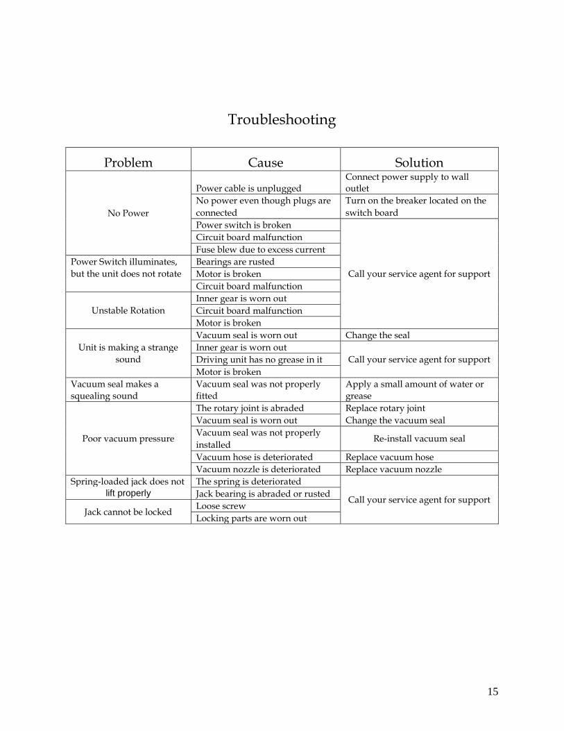
Troubleshooting
Problem Cause Solution
No Power
Power cable is unplugged Connect power supply to wall outlet
No power even though plugs are Turn on the breaker located on the
connected switch board
Power switch is broken
Call your service agent for support
Circuit board malfunction
Fuse blew due to excess current
Power Switch illuminates, Bearings are rusted
but the unit does not rotate Motor is broken
Circuit board malfunction
Unstable Rotation
Inner gear is worn out
Circuit board malfunction
Motor is broken
Unit is making a strange
Vacuum seal is worn out Change the seal
Inner gear is worn out
Call your service agent for support sound Driving unit has no grease in it
Motor is broken
Vacuum seal makes a Vacuum seal was not properly Apply a small amount of water or
squealing sound fitted grease
Poor vacuum pressure
The rotary joint is abraded Replace rotary joint
Vacuum seal is worn out Change the vacuum seal
Vacuum seal was not properly Re-install vacuum seal
installed
Vacuum hose is deteriorated Replace vacuum hose
Vacuum nozzle is deteriorated Replace vacuum nozzle
Spring-loaded jack does not The spring is deteriorated
Call your service agent for support lift properly Jack bearing is abraded or rusted
Jack cannot be locked Loose screw
Locking parts are worn out
16