Embed Size (px)
Citation preview
1
IS370 Data Communications
and Computer Networks
Chapter 4 : Network Layer
Instructor : Mr Mourad Benchikh
2
Introduction • Responsible for the source-to-destination delivery
of individual packets possibly across multiple networks (LANs or WANs) –internetworking?.– Multiple and may be heterogeneous networks.– Recall: data-link layer offers only a hop-to-hop delivery
on the same network
• Defining a logical addressing that globally and uniquely identify each host and router.
• Referred as IP addressing in the Internet.
• Provides a routing mechanism to route packets to their final destination in internetwork.– In particular, find the best (optimal) route for the packet
when many routes exist.
3
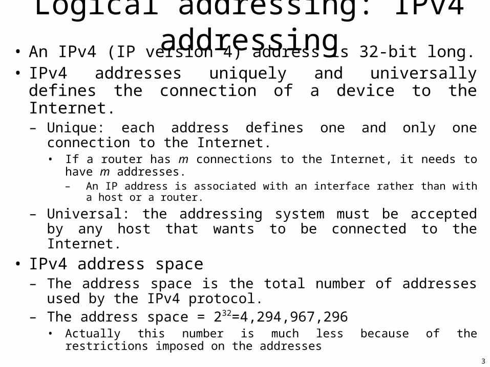
Logical addressing: IPv4 addressing• An IPv4 (IP version 4) address is 32-bit long.• IPv4 addresses uniquely and universally defines the
connection of a device to the Internet.– Unique: each address defines one and only one connection to
the Internet.• If a router has m connections to the Internet, it needs to have m
addresses.– An IP address is associated with an interface rather than with a host or a
router.
– Universal: the addressing system must be accepted by any host that wants to be connected to the Internet.
• IPv4 address space– The address space is the total number of addresses used by the
IPv4 protocol.– The address space = 232=4,294,967,296
• Actually this number is much less because of the restrictions imposed on the addresses
4
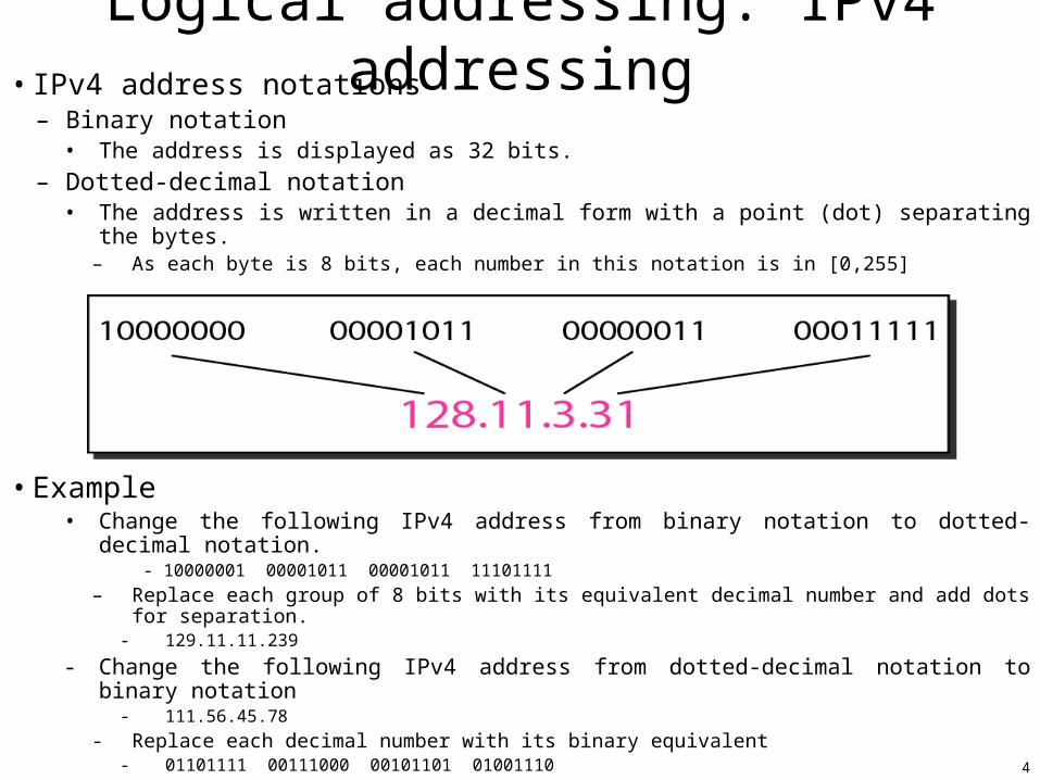
Logical addressing: IPv4 addressing• IPv4 address notations
– Binary notation• The address is displayed as 32 bits.
– Dotted-decimal notation• The address is written in a decimal form with a point (dot) separating the bytes.
– As each byte is 8 bits, each number in this notation is in [0,255]
• Example• Change the following IPv4 address from binary notation to dotted-decimal notation.
- 10000001 00001011 00001011 11101111
– Replace each group of 8 bits with its equivalent decimal number and add dots for separation.- 129.11.11.239
- Change the following IPv4 address from dotted-decimal notation to binary notation- 111.56.45.78
- Replace each decimal number with its binary equivalent- 01101111 00111000 00101101 01001110
5
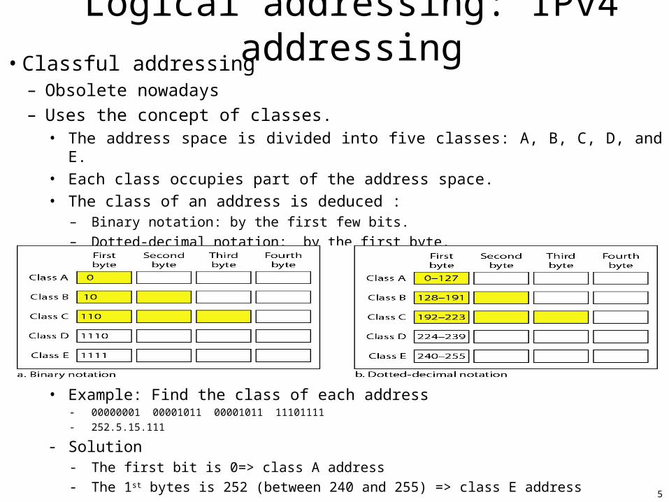
Logical addressing: IPv4 addressing• Classful addressing
– Obsolete nowadays
– Uses the concept of classes.• The address space is divided into five classes: A, B, C, D, and E.
• Each class occupies part of the address space.
• The class of an address is deduced :– Binary notation: by the first few bits.
– Dotted-decimal notation: by the first byte.
• Example: Find the class of each address- 00000001 00001011 00001011 11101111
- 252.5.15.111
- Solution- The first bit is 0=> class A address
- The 1st bytes is 252 (between 240 and 255) => class E address
6
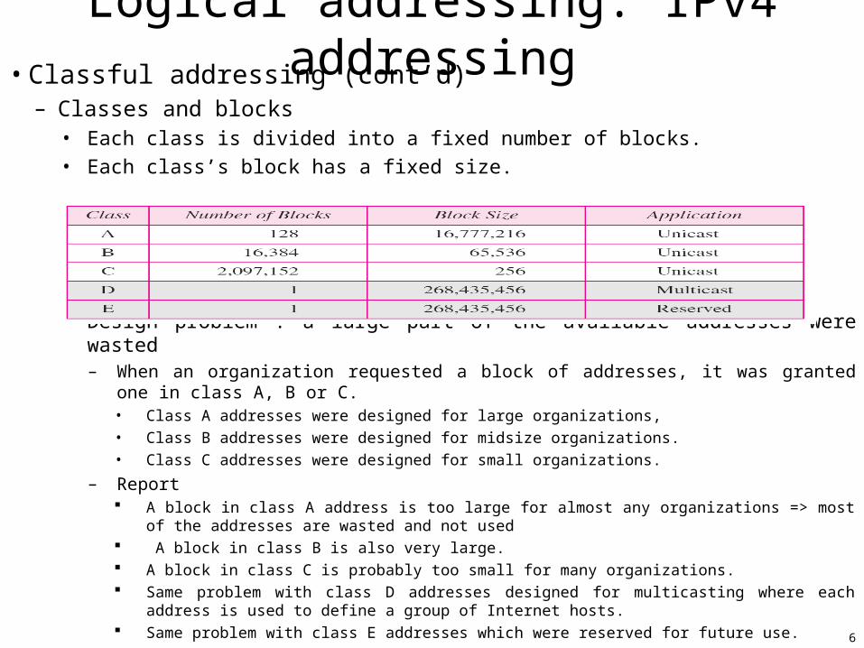
Logical addressing: IPv4 addressing• Classful addressing (cont’d)
– Classes and blocks• Each class is divided into a fixed number of blocks.
• Each class’s block has a fixed size.
• Design problem : a large part of the available addresses were wasted – When an organization requested a block of addresses, it was granted one in class A, B or C.
• Class A addresses were designed for large organizations,
• Class B addresses were designed for midsize organizations.
• Class C addresses were designed for small organizations.
– Report A block in class A address is too large for almost any organizations => most of the addresses are
wasted and not used A block in class B is also very large. A block in class C is probably too small for many organizations. Same problem with class D addresses designed for multicasting where each address is used to define a
group of Internet hosts. Same problem with class E addresses which were reserved for future use.
7
Logical addressing: IPv4 addressing• Classful addressing (cont’d)
– Netid and Hostid• An IP address in class A, B, or C is divided into netid and hostid.
– In the previous figure, the netid is in color while the hostid is in white. EX. class C: three bytes define the netid and one byte the hostid.
– The concept of netid and hostid doesn’t apply to class D and E.
– Mask• Can be used to find the netid and the hostid.
– The concept doesn’t apply to class D and E.
• It is a 32-bit made of contiguous 1s followed by contiguous 0s.– Ex. class A: its mask is predetermined and has eight 1s.
=> the first 8 bits of any of a class A address define the netid and the remaining 24 bits define the hostid.
• Could be written using the slash (or CIDR (Classless Interdomain Routing)) notation [RFC1519].– The mask is then written in the form /n ; n can be 8, 16, or 24 in classful addressing
– Subnetting• An organization’s large block (A or B) could be divided into several contiguous groups
– Each group is assigned to smaller networks (i.e. subnets)• Split a network into several parts (subnets) for internal use. The network is always single entity to outside world=>simplify addressing and routing.
– Supernetting• An organization can combine several class C blocks to create a large range of addresses.• => several networks are combined to create a supernetwork or a supernet.
– A organization that needs 1000 addresses can be granted four contiguous class C blocks (each with 256 addresses).
– Classfull addressing leads to the near depletion of the available addresses with the growth of the Internet although the number of Internet devices < 232 => replaced by the classless addressing.
• 1) run out class A and B addresses and 2) a class C block is too small for most midsize organizations.
8
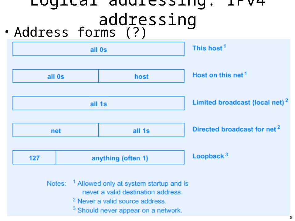
Logical addressing: IPv4 addressing• Address forms (?)
9
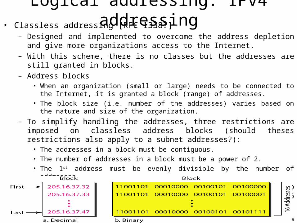
Logical addressing: IPv4 addressing• Classless addressing [RFC 1338?]
– Designed and implemented to overcome the address depletion and give more organizations access to the Internet.
– With this scheme, there is no classes but the addresses are still granted in blocks.
– Address blocks• When an organization (small or large) needs to be connected to the Internet, it is granted a
block (range) of addresses.
• The block size (i.e. number of the addresses) varies based on the nature and size of the organization.
– To simplify handling the addresses, three restrictions are imposed on classless address blocks (should theses restrictions also apply to a subnet addresses?):
• The addresses in a block must be contiguous.
• The number of addresses in a block must be a power of 2.
• The 1st address must be evenly divisible by the number of addresses.
– An example showing a block of addresses (in the two notations) granted to a small business that needs 16 addresses.
10
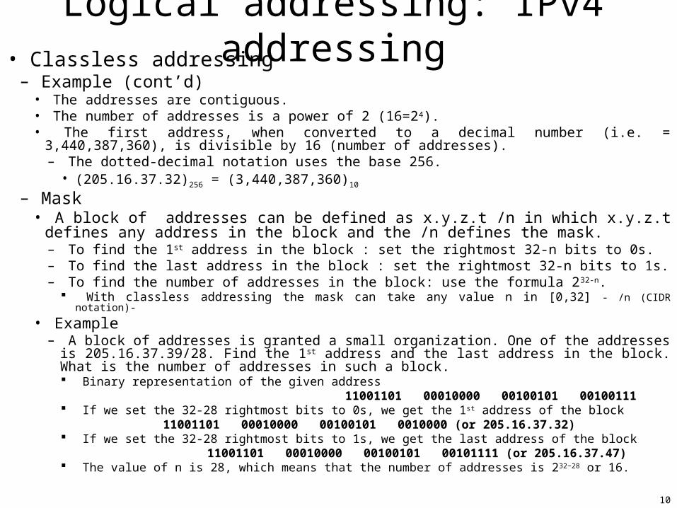
Logical addressing: IPv4 addressing• Classless addressing
– Example (cont’d)• The addresses are contiguous.• The number of addresses is a power of 2 (16=24).• The first address, when converted to a decimal number (i.e. = 3,440,387,360), is divisible by 16
(number of addresses).– The dotted-decimal notation uses the base 256.
• (205.16.37.32)256 = (3,440,387,360)10
– Mask• A block of addresses can be defined as x.y.z.t /n in which x.y.z.t defines any address in
the block and the /n defines the mask.– To find the 1st address in the block : set the rightmost 32-n bits to 0s.– To find the last address in the block : set the rightmost 32-n bits to 1s.– To find the number of addresses in the block: use the formula 232-n.
With classless addressing the mask can take any value n in [0,32] - /n (CIDR notation)-
• Example– A block of addresses is granted a small organization. One of the addresses is 205.16.37.39/28. Find
the 1st address and the last address in the block. What is the number of addresses in such a block. Binary representation of the given address 11001101 00010000 00100101 00100111 If we set the 32-28 rightmost bits to 0s, we get the 1st address of the block
11001101 00010000 00100101 0010000 (or 205.16.37.32) If we set the 32-28 rightmost bits to 1s, we get the last address of the block
11001101 00010000 00100101 00101111 (or 205.16.37.47) The value of n is 28, which means that the number of addresses is 232−28 or 16.
11
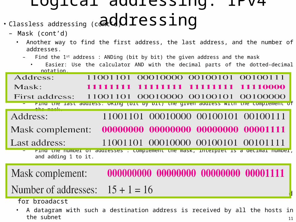
Logical addressing: IPv4 addressing• Classless addressing (cont’d)
– Mask (cont’d)• Another way to find the first address, the last address, and the number of addresses.
– Find the 1st address : ANDing (bit by bit) the given address and the mask
• Easier: Use the calculator AND with the decimal parts of the dotted-decimal notation.
– Find the last address: ORing (bit by bit) the given address with the complement of the mask.
– Find the number of addresses : complement the mask, interpret is a decimal number, and adding 1 to it.
– Note that the 255.255.255.255 IPv4 address is a special address used for broadacst• A datagram with such a destination address is received by all the hosts in the subnet
12
Logical addressing: IPv4 addressing• Classless addressing (cont’d)
– Network addresses (and broadcast addresses??)• When an organization is given a block of addresses, the organization is free to allocate the addresses to
the devices that need to be connected to the Internet.
• However, the 1st address is called the network address and defines the organization network.– This address is normally (not always) not assigned to any device.
– It defines the organization to the rest of the world.
• Note also that the last address is the broadcast address, i.e. meaning all the network (subnet) hosts (?)
• EX.– The organization network is connected to the Internet via a router.
– The router has two addresses: one belongs to the granted block and the other, noted x.y.z.t/n, belongs to the network that is at the other side of the router.
– All messages destined for addresses in the organization block are sent to x.y.z.t/n
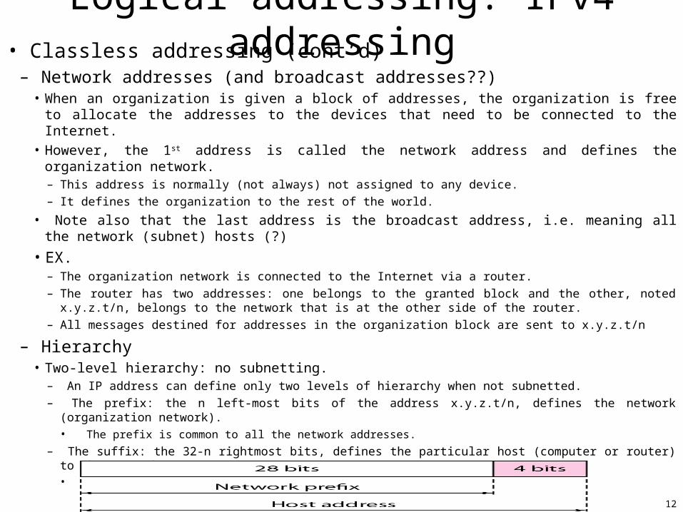
– Hierarchy• Two-level hierarchy: no subnetting.
– An IP address can define only two levels of hierarchy when not subnetted.
– The prefix: the n left-most bits of the address x.y.z.t/n, defines the network (organization network).• The prefix is common to all the network addresses.
– The suffix: the 32-n rightmost bits, defines the particular host (computer or router) to the network. • The suffix changes from one device to another.
13
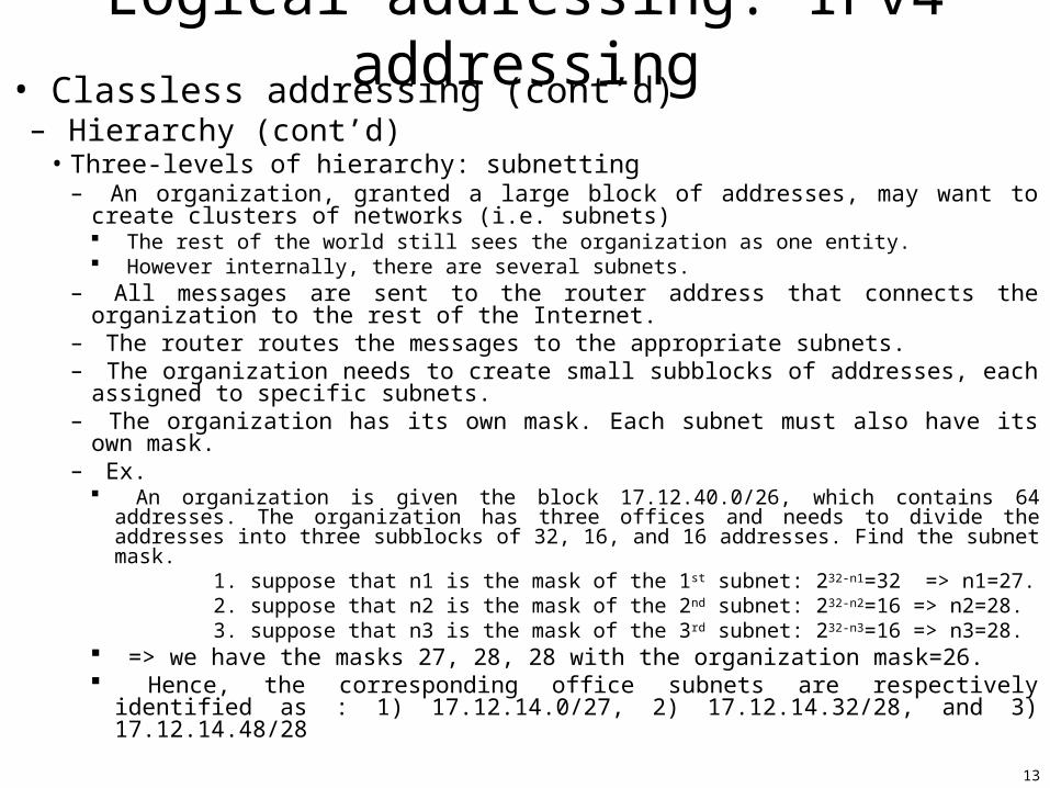
Logical addressing: IPv4 addressing• Classless addressing (cont’d)
– Hierarchy (cont’d)•Three-levels of hierarchy: subnetting
– An organization, granted a large block of addresses, may want to create clusters of networks (i.e. subnets) The rest of the world still sees the organization as one entity. However internally, there are several subnets.
– All messages are sent to the router address that connects the organization to the rest of the Internet.
– The router routes the messages to the appropriate subnets.– The organization needs to create small subblocks of addresses, each assigned to specific
subnets.– The organization has its own mask. Each subnet must also have its own mask.– Ex.
An organization is given the block 17.12.40.0/26, which contains 64 addresses. The organization has three offices and needs to divide the addresses into three subblocks of 32, 16, and 16 addresses. Find the subnet mask.
1. suppose that n1 is the mask of the 1st subnet: 232-n1=32 => n1=27. 2. suppose that n2 is the mask of the 2nd subnet: 232-n2=16 => n2=28. 3. suppose that n3 is the mask of the 3rd subnet: 232-n3=16 => n3=28. => we have the masks 27, 28, 28 with the organization mask=26. Hence, the corresponding office subnets are respectively identified as : 1)
17.12.14.0/27, 2) 17.12.14.32/28, and 3) 17.12.14.48/28
14
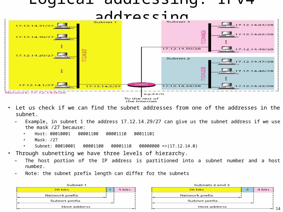
Logical addressing: IPv4 addressing
• Let us check if we can find the subnet addresses from one of the addresses in the subnet.– Example, in subnet 1 the address 17.12.14.29/27 can give us the subnet address if we use the mask /27
because:• Host: 00010001 00001100 00001110 00011101
• Mask: /27
• Subnet: 00010001 00001100 00001110 00000000 =>(17.12.14.0)
• Through subnetting we have three levels of hierarchy.– The host portion of the IP address is partitioned into a subnet number and a host number.– Note: the subnet prefix length can differ for the subnets
15
Logical addressing: IPv4 addressing• Classless addressing (cont’d)
– More levels of hierarchy• No restriction of the number of hierarchy with classless addressing.• => each subblock can in turn be divided into smaller subblocks.
– Address allocation• A global authority, called ICANN [RFC 1519] (Internet Corporation for
Assigned Names and Addresses), has the responsibility of address allocation.
• ICANN normally assigns a block of addresses to an ISP, which in turn, divides the block into smaller subblocks and grants the subblocks to its customers.
– Address aggregation: many blocks of addresses are aggregated into one block and granted to one ISP.
– Example:• An ISP is granted a block of addresses starting with 190.100.0.0/16 (65,536
addresses). The ISP needs to distribute these addresses to three groups of customers as follows:
– Group1: The first group has 64 customers; each needs 256 addresses.– Group2: The second group has 128 customers; each needs 128 addresses – Group3: The third group has 128 customers; each needs 64 addresses.
Design the subblocks and find out how many addresses are still available after these allocations.
16
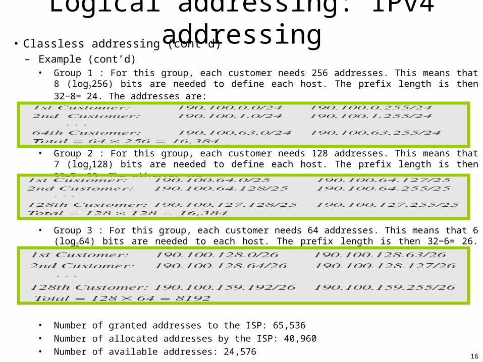
Logical addressing: IPv4 addressing• Classless addressing (cont’d)
– Example (cont’d)• Group 1 : For this group, each customer needs 256 addresses. This means that 8 (log2256) bits
are needed to define each host. The prefix length is then 32−8= 24. The addresses are:
• Group 2 : For this group, each customer needs 128 addresses. This means that 7 (log2128) bits are needed to define each host. The prefix length is then 32−7= 25. The addresses are:
• Group 3 : For this group, each customer needs 64 addresses. This means that 6 (log264) bits are needed to each host. The prefix length is then 32−6= 26. The addresses are:
• Number of granted addresses to the ISP: 65,536
• Number of allocated addresses by the ISP: 40,960
• Number of available addresses: 24,576
17
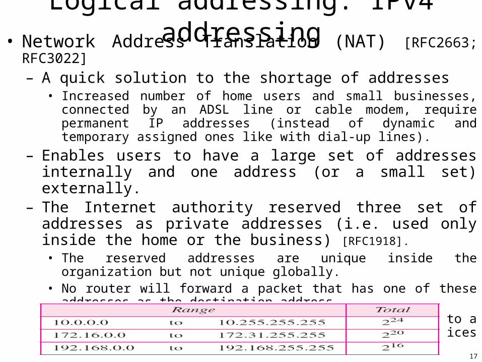
Logical addressing: IPv4 addressing• Network Address Translation (NAT) [RFC2663; RFC3022]
– A quick solution to the shortage of addresses• Increased number of home users and small businesses, connected by an
ADSL line or cable modem, require permanent IP addresses (instead of dynamic and temporary assigned ones like with dial-up lines).
– Enables users to have a large set of addresses internally and one address (or a small set) externally.
– The Internet authority reserved three set of addresses as private addresses (i.e. used only inside the home or the business) [RFC1918].
• The reserved addresses are unique inside the organization but not unique globally.
• No router will forward a packet that has one of these addresses as the destination address.
• => A private network with private addresses refers to a network whose addresses only have meaning to devices within that network.
18
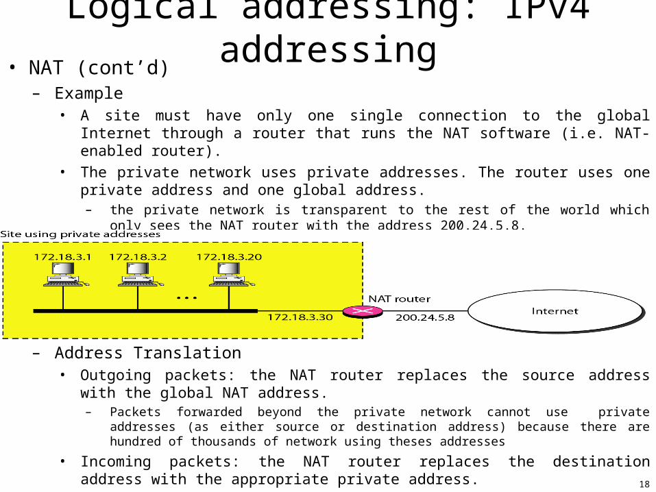
Logical addressing: IPv4 addressing• NAT (cont’d)
– Example• A site must have only one single connection to the global Internet through a router
that runs the NAT software (i.e. NAT-enabled router).
• The private network uses private addresses. The router uses one private address and one global address.
– the private network is transparent to the rest of the world which only sees the NAT router with the address 200.24.5.8.
– Address Translation• Outgoing packets: the NAT router replaces the source address with the global NAT
address.– Packets forwarded beyond the private network cannot use private addresses (as either source or
destination address) because there are hundred of thousands of network using theses addresses
• Incoming packets: the NAT router replaces the destination address with the appropriate private address.
19
Logical addressing: IPv4 addressing• NAT (cont’d)
– Translation table• Used to translate the incoming packets.
– How to know the destination address of an incoming packet among many private IP addresses?• Translating the source address of outgoing packets is straightforward,
• Using one IP address– The table has two columns: the private address and the external address (destination address of
the packet).– The router makes note of the destination address -when the packet is going- and uses the source
address of an incoming packet to find the private address of the packet.• Using a pool of IP addresses.
– NAT router uses a pool of global addresses.• With only one global address, only one private network host can access the same external host.• Ex: if four global addresses are used, then four private network hosts can communicate with the same external host at the same
time.
• Using both IP addresses and port numbers– Allow a many-to-many relationship between private-network hosts and external server programs.– The translation table has now 5 columns:
• Private address, Private port, External Address, External port, and Transport Protocol.
– NAT and ISPs• An ISP serving dial-up customers can use NAT technology to conserve addresses.
– An ISP is granted 1000 addresses but has 100000 custumers. Each customer is assigned a private network address. The ISP translates each of the 100000 source addresses in outgoing packets to one of the 1000 global addresses.
– It translates the global address in incoming packets to the corresponding private address.
20
Logical addressing: IPv6 addresses• Motivation:
– Long-term problem of address depletion • Despite short-term solutions: classless addressing, subnetting, NAT, DHCP.
– Other problems with IPv4 protocol• Lack of accommodation for real-time audio and video transmission, encryption, and authentication.
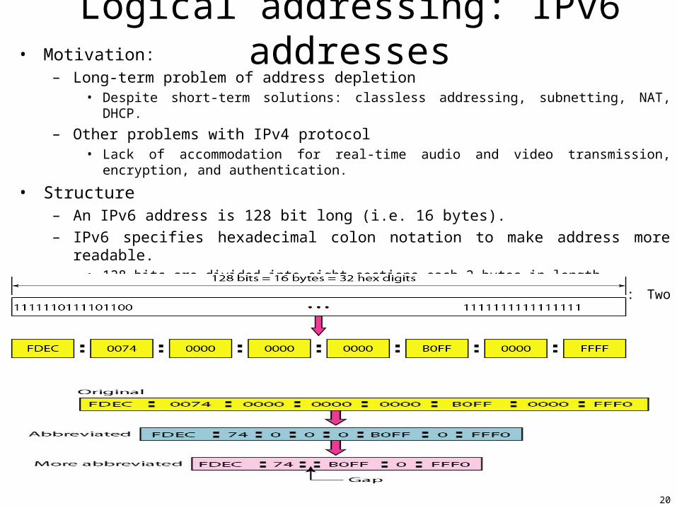
• Structure– An IPv6 address is 128 bit long (i.e. 16 bytes).
– IPv6 specifies hexadecimal colon notation to make address more readable. • 128 bits are divided into eight sections each 2 bytes in length.
• 32 hexadecimal digits (every four digit separated by a colon): Two bytes in hexadecimal notation require four hexadecimal digits.
– Abbreviation
21
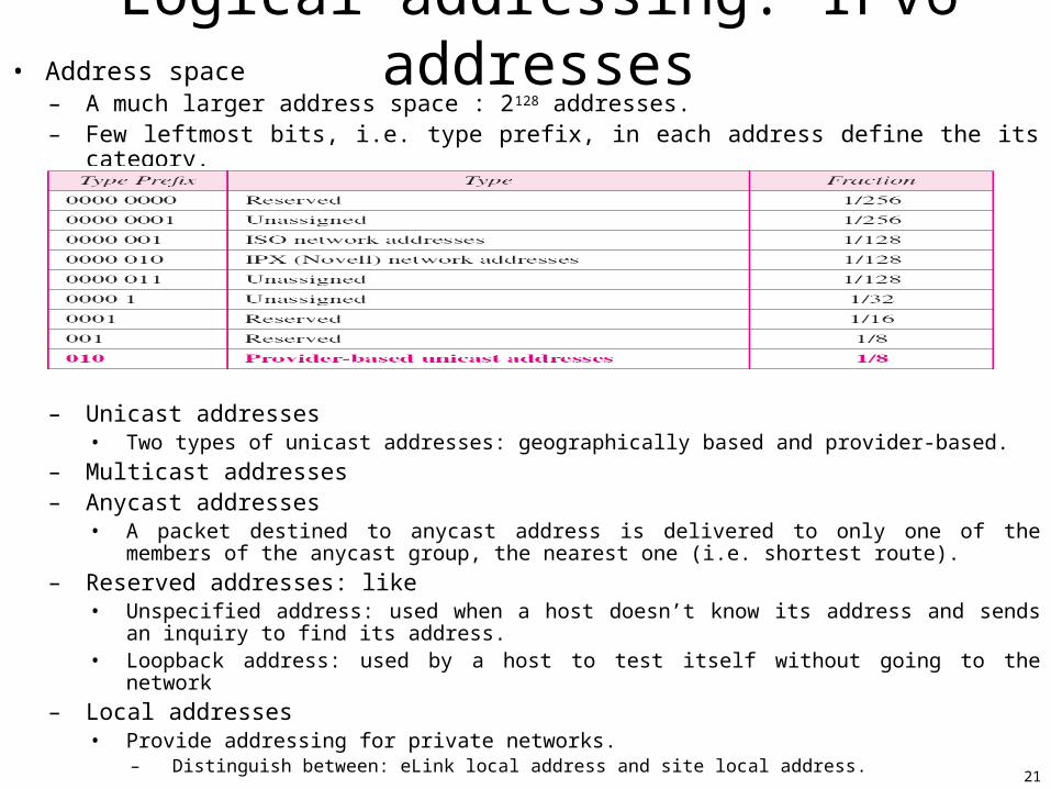
Logical addressing: IPv6 addresses• Address space
– A much larger address space : 2128 addresses.– Few leftmost bits, i.e. type prefix, in each address define the its category.
– Unicast addresses• Two types of unicast addresses: geographically based and provider-based.
– Multicast addresses– Anycast addresses
• A packet destined to anycast address is delivered to only one of the members of the anycast group, the nearest one (i.e. shortest route).
– Reserved addresses: like• Unspecified address: used when a host doesn’t know its address and sends an inquiry to find its
address.• Loopback address: used by a host to test itself without going to the network
– Local addresses• Provide addressing for private networks.
– Distinguish between: eLink local address and site local address.
22
Internet Protocol• Main network protocol that supervises and controls the delivery of packets from the source to
destination in the Internet.
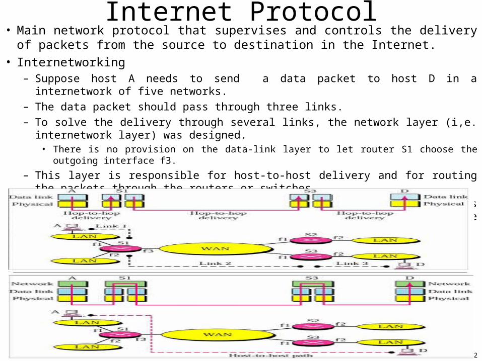
• Internetworking– Suppose host A needs to send a data packet to host D in a internetwork of five networks.
– The data packet should pass through three links.
– To solve the delivery through several links, the network layer (i,e. internetwork layer) was designed.• There is no provision on the data-link layer to let router S1 choose the outgoing interface f3.
– This layer is responsible for host-to-host delivery and for routing the packets through the routers or switches.
– The provided internetworking introduces abstractions that hides details of underlying networks (possibly heterogeneous) => provide the illusion of a single large network.
23
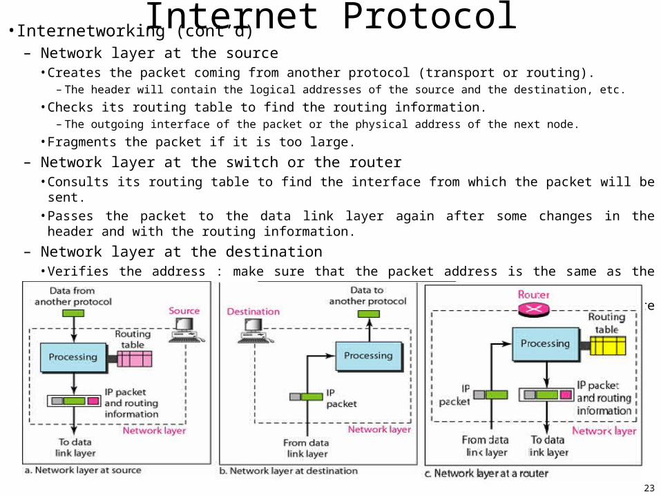
Internet Protocol• Internetworking (cont’d)– Network layer at the source
• Creates the packet coming from another protocol (transport or routing).– The header will contain the logical addresses of the source and the destination, etc.
• Checks its routing table to find the routing information.– The outgoing interface of the packet or the physical address of the next node.
• Fragments the packet if it is too large.
– Network layer at the switch or the router• Consults its routing table to find the interface from which the packet will be sent.
• Passes the packet to the data link layer again after some changes in the header and with the routing information.
– Network layer at the destination• Verifies the address : make sure that the packet address is the same as the host address.
• If the packet is a fragment, it will wait until all the packet’s fragments are reassembled before to deliver the packet to the transport layer.
24
Internet Protocol• Internetworking (cont’d)
– The Internet has chosen the datagram approach to switching in the network layer.• It uses the IP address to route packets from the source to destination.
– Communication at the network layer in the Internet is connectionless (vs. a connection-oriented)
• Each packet is treated independently by the network layer.– The packets in a message may or may not travel the same path to their destination.
• Connectionless reason : the Internet is made of so many heterogeneous networks that it is almost impossible to create a connection from the source to the destination without knowing the nature of the networks in advance.
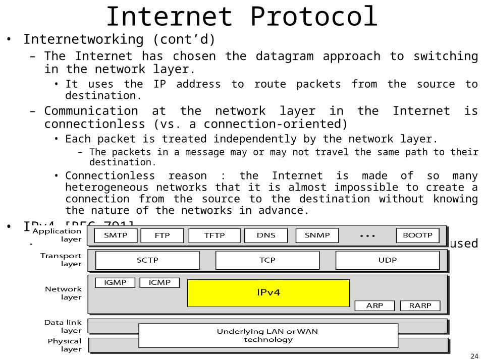
• IPv4 [RFC 791]– Internet Protocol version 4 is the delivery mechanism used currently by the TCP/IP
protocols.
25
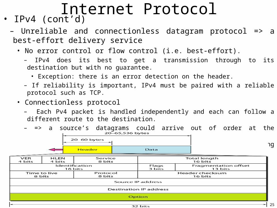
Internet Protocol• IPv4 (cont’d)
– Unreliable and connectionless datagram protocol => a best-effort delivery service• No error control or flow control (i.e. best-effort).
– IPv4 does its best to get a transmission through to its destination but with no guarantee.
• Exception: there is an error detection on the header.
– If reliability is important, IPv4 must be paired with a reliable protocol such as TCP.
• Connectionless protocol– Each Pv4 packet is handled independently and each can follow a different route to the destination.
– => a source’s datagrams could arrive out of order at the destination.
–=> a source’s datagrams could be lost or corrupted during transmission.
– Datagram (i.e. an IPv4 packet)
• A variable-length packet consisting of two parts: header and data
26
Internet Protocol• IPv4 (cont’d)
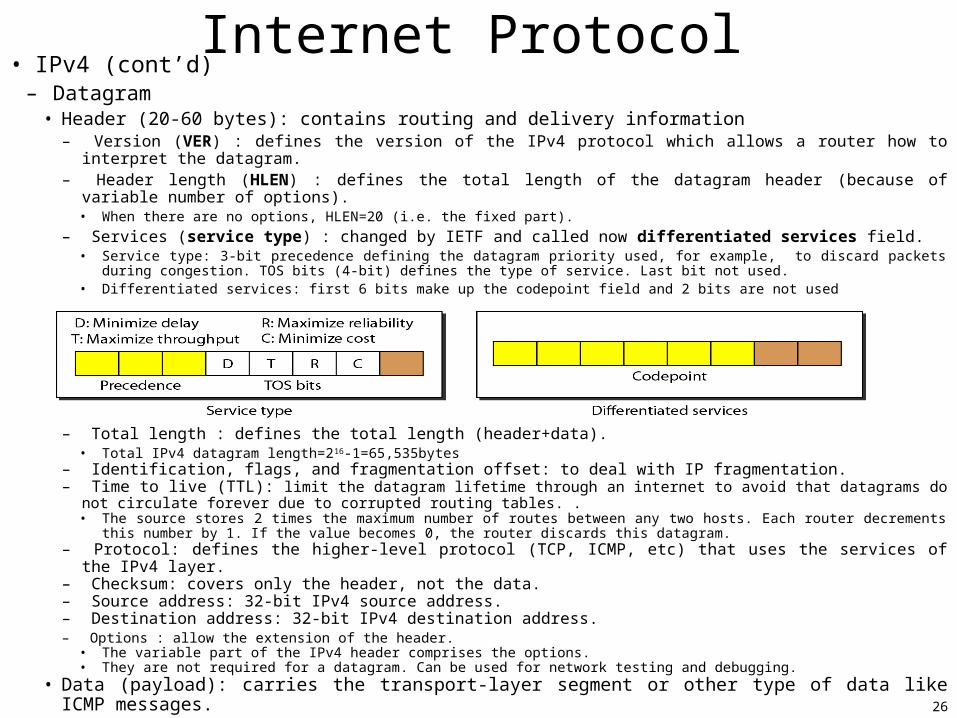
– Datagram• Header (20-60 bytes): contains routing and delivery information
– Version (VER) : defines the version of the IPv4 protocol which allows a router how to interpret the datagram.– Header length (HLEN) : defines the total length of the datagram header (because of variable number of options).
• When there are no options, HLEN=20 (i.e. the fixed part).
– Services (service type) : changed by IETF and called now differentiated services field.• Service type: 3-bit precedence defining the datagram priority used, for example, to discard packets during congestion. TOS bits
(4-bit) defines the type of service. Last bit not used.• Differentiated services: first 6 bits make up the codepoint field and 2 bits are not used
– Total length : defines the total length (header+data).• Total IPv4 datagram length=216-1=65,535bytes
– Identification, flags, and fragmentation offset: to deal with IP fragmentation.– Time to live (TTL): limit the datagram lifetime through an internet to avoid that datagrams do not circulate forever due
to corrupted routing tables. . • The source stores 2 times the maximum number of routes between any two hosts. Each router decrements this number by 1. If the
value becomes 0, the router discards this datagram. – Protocol: defines the higher-level protocol (TCP, ICMP, etc) that uses the services of the IPv4 layer. – Checksum: covers only the header, not the data.– Source address: 32-bit IPv4 source address.– Destination address: 32-bit IPv4 destination address.– Options : allow the extension of the header.
• The variable part of the IPv4 header comprises the options.• They are not required for a datagram. Can be used for network testing and debugging.
• Data (payload): carries the transport-layer segment or other type of data like ICMP messages.
27
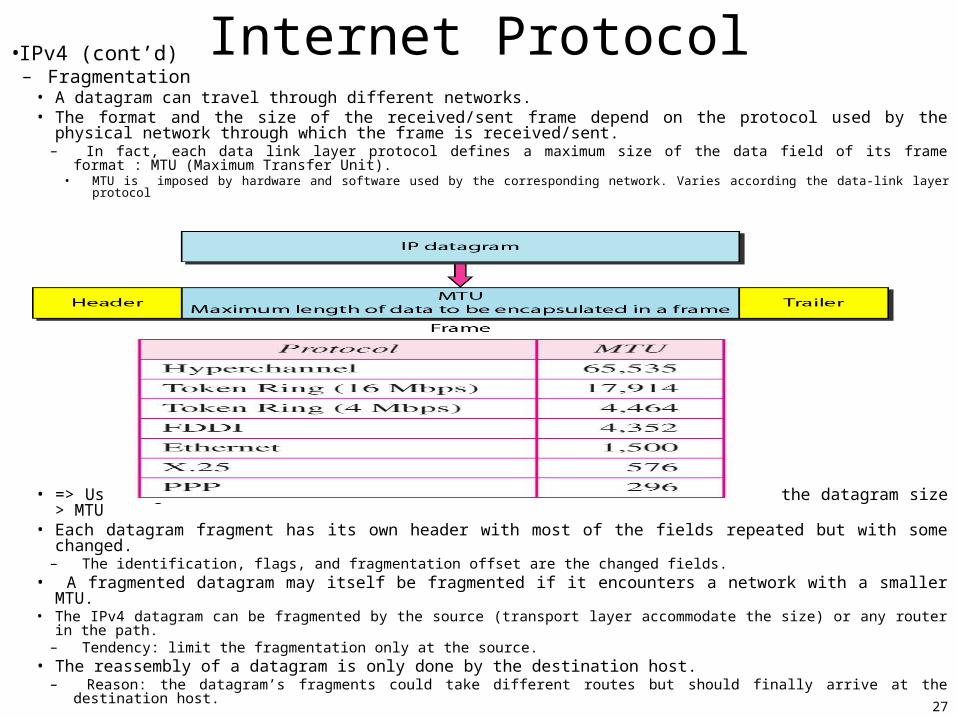
Internet Protocol•IPv4 (cont’d)– Fragmentation
• A datagram can travel through different networks.• The format and the size of the received/sent frame depend on the protocol used by the physical
network through which the frame is received/sent.– In fact, each data link layer protocol defines a maximum size of the data field of its frame format : MTU
(Maximum Transfer Unit).• MTU is imposed by hardware and software used by the corresponding network. Varies according the data-link layer protocol
• => Use fragmentation (i.e. divide the datagram into two or more smaller datagrams) when the datagram size > MTU • Each datagram fragment has its own header with most of the fields repeated but with some changed.
– The identification, flags, and fragmentation offset are the changed fields.• A fragmented datagram may itself be fragmented if it encounters a network with a smaller MTU.• The IPv4 datagram can be fragmented by the source (transport layer accommodate the size) or any router in the path.
– Tendency: limit the fragmentation only at the source.• The reassembly of a datagram is only done by the destination host.
– Reason: the datagram’s fragments could take different routes but should finally arrive at the destination host.
28
Internet Protocol•IPv6 (also known as IPng (Internetworking Protocol, next generation) [RFC 2460, RFC
3513]
– Overcome IPv4 deficiencies.– Advantages IPv6 vs. IPv4
• Larger address space: an IPv6 address is 128 bit long.• Better header format: a new header format is used.• New options: new options for additional functionalities.• Allowance for extension: allows the protocol extension if required by new technologies or applications.• Support for resource allocations: flow label mechanism has been added to enable requesting special handling of the
packet. Could support real-time audio and video traffic. ToS field has been removed.• Support for more security: added encryption and authentication options.
– Packet format: each packet is composed of:• Mandatory base header: with eight fields
– Version.– Priority : used during traffic congestion.– Flow label: provides special handling for a particular flow of data.– Payload length: defines the IP datagram length excluding the base header.– Next header: defines the header that follows the base header.– Hop limit: same as TTL.– Source address.– Destination address.
• Extension header– The base header can be followed by up to 6 extension headers.– Many of these headers are options in IPv4.– Six types of extension headers have been defined: hop-by-hop option, source routing, fragmentation,
authentication, encrypted security payload, and destination option.
• Payload (data)
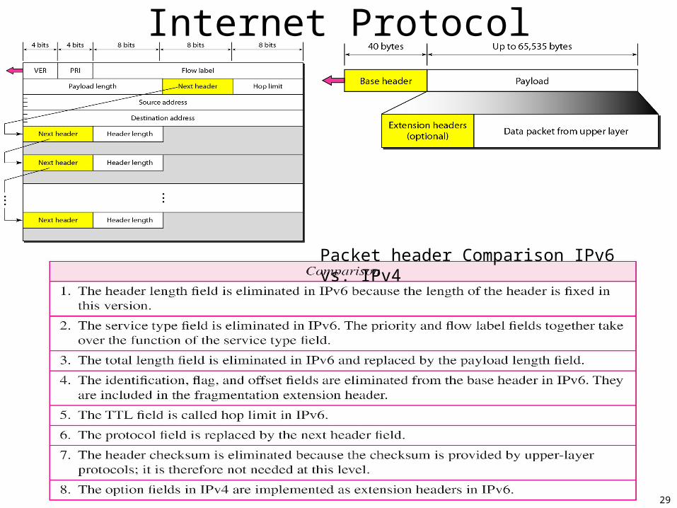
29
Internet Protocol
Packet header Comparison IPv6 vs. IPv4
30
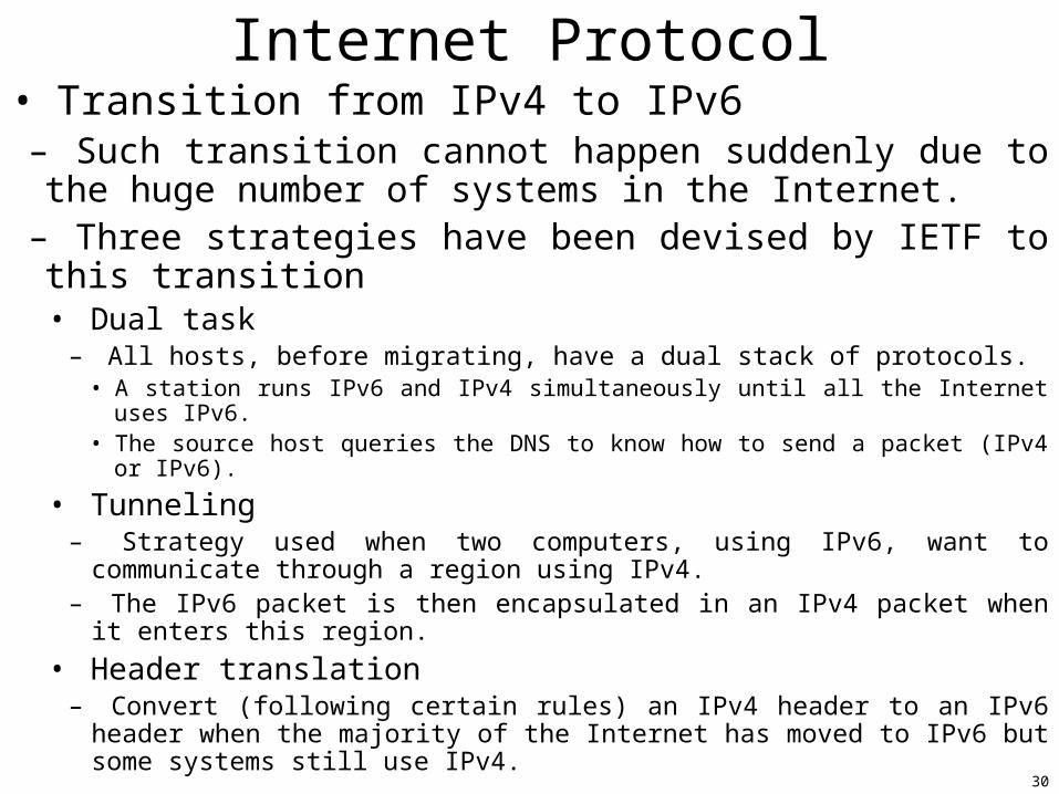
Internet Protocol• Transition from IPv4 to IPv6
– Such transition cannot happen suddenly due to the huge number of systems in the Internet.
– Three strategies have been devised by IETF to this transition • Dual task
– All hosts, before migrating, have a dual stack of protocols.• A station runs IPv6 and IPv4 simultaneously until all the Internet uses IPv6.• The source host queries the DNS to know how to send a packet (IPv4 or IPv6).
• Tunneling– Strategy used when two computers, using IPv6, want to communicate through a region using IPv4.
– The IPv6 packet is then encapsulated in an IPv4 packet when it enters this region.
• Header translation– Convert (following certain rules) an IPv4 header to an IPv6 header when the majority of the Internet has moved to IPv6 but some systems still use IPv4.
31
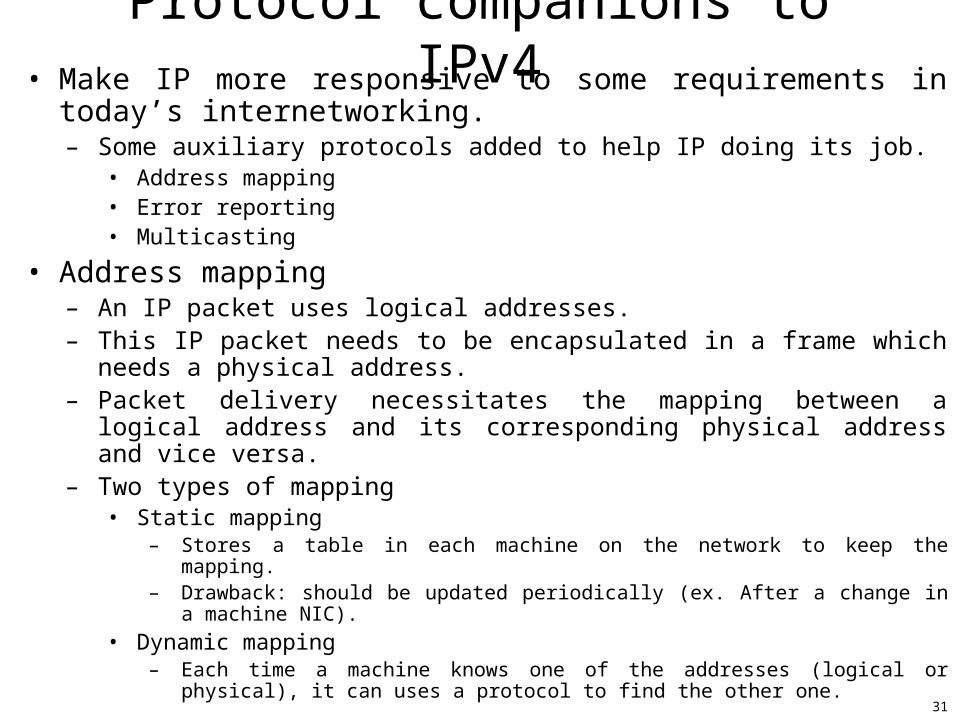
Protocol companions to IPv4• Make IP more responsive to some requirements in today’s
internetworking.– Some auxiliary protocols added to help IP doing its job.
• Address mapping• Error reporting• Multicasting
• Address mapping– An IP packet uses logical addresses.– This IP packet needs to be encapsulated in a frame which needs a physical
address.– Packet delivery necessitates the mapping between a logical address and its
corresponding physical address and vice versa.– Two types of mapping
• Static mapping– Stores a table in each machine on the network to keep the mapping.– Drawback: should be updated periodically (ex. After a change in a machine NIC).
• Dynamic mapping– Each time a machine knows one of the addresses (logical or physical), it can uses a
protocol to find the other one.
32
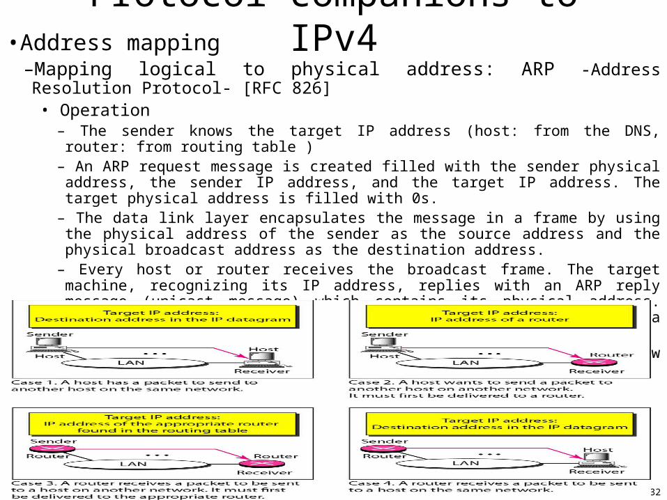
Protocol companions to IPv4•Address mapping
–Mapping logical to physical address: ARP -Address Resolution Protocol- [RFC 826]• Operation
– The sender knows the target IP address (host: from the DNS, router: from routing table )– An ARP request message is created filled with the sender physical address, the sender IP address,
and the target IP address. The target physical address is filled with 0s.– The data link layer encapsulates the message in a frame by using the physical address of the sender
as the source address and the physical broadcast address as the destination address.– Every host or router receives the broadcast frame. The target machine, recognizing its IP address,
replies with an ARP reply message (unicast message) which contains its physical address. This message is directly encapsulated into the corresponding data link layer frame,.
– The sender receives the reply message. The IP datagram is now encapsulated in a frame and is unicast to the destination.
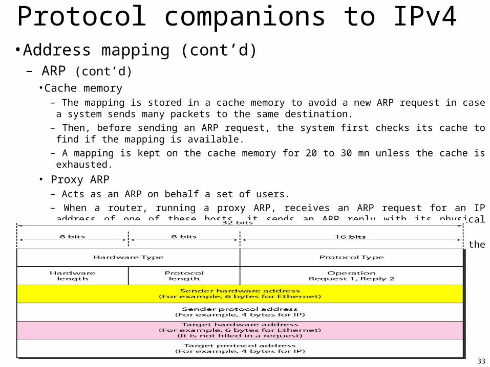
• The use of ARP: four cases
33
Protocol companions to IPv4•Address mapping (cont’d)
– ARP (cont’d)• Cache memory
– The mapping is stored in a cache memory to avoid a new ARP request in case a system sends many packets to the same destination.
– Then, before sending an ARP request, the system first checks its cache to find if the mapping is available.
– A mapping is kept on the cache memory for 20 to 30 mn unless the cache is exhausted.
• Proxy ARP– Acts as an ARP on behalf a set of users.
– When a router, running a proxy ARP, receives an ARP request for an IP address of one of these hosts, it sends an ARP reply with its physical address.
– After the router receives the actual IP packet, it sends the packet to the appropriate host or router.
• ARP packet
34
Protocol companions to IPv4•Address mapping (cont’d)
– Mapping physical to logical address: RARP, BOOTP, and DHCP.• Two cases where a host knows its physical address but needs to know its logical address
–A diskless station is just booted.–An organization assigns IP addresses on demand because no enough IP addresses are available.
– RARP -Reverse Address Resolution Protocol-• The requesting machine, that should running a RARP client program, broadcasts an RARP request on the local network.
• The responding machine, that should running a RARP server and knows all the IP addresses, will respond with an RARP reply.
• Drawback: RARP broadcasting is done at the data link layer => impossible to pass the network boundaries.
–The administrator needs to assign a RARP server on each network or subnet he manages.– BOOTP –Bootstrap Protocol-
• An client/server application layer protocol to provide the mapping.–A client can be in one network and the server in another (advantage of BOOTP over RARP).
• The binding between the physical and logical addresses is static and fixed manually in a table.
–Problems: what if a host moves from one physical network to another? What if a host wants a temporary IP address.
– DHCP (Dynamic Host Configuration Protocol) [RFC 2131]• Provides static and dynamic address allocation that can be manual or automatic.
–1) Static address allocation: in this case, DHCP acts as BOOTP does using a static database (permanent IP addresses).
35
Protocol companions to IPv4• Address mapping (cont’d)
– DHCP (cont’d)• 2) Dynamic address allocation
• DHCP has a pool of available IP addresses in its dynamic database (temporary addresses).• When DHCP client sends a request to a DHCP server, the server checks its static database if there is
a permanent address to the corresponding physical address. The permanent IP address is then returned to the client.
• Otherwise, the server selects an IP address from the pool, assigns the address to the client, and adds an entry to the dynamic database.
• Temporary addresses are provided for a limited time. When the lease expire, the client must stop using the IP address or renew the lease.
• Static (i.e permanent) addresses are created manually• Dynamic (i.e. temporary) addresses are created automatically.• DHCP allows also a host to know: its subnet mask, the address of the 1 st-hop router, and the address of
its local DNS server.• Simple form : each subnet has a DHCP server. Otherwise, DHCP relay agent (typically a router), that
knows the DHCP address, is needed.• DHCP four-steps process for a newly arriving host requesting an IP address
1. DHCP server discovery: to find the DHCP server, the client (a new arriving host) sends a DHCP discover message within a UDP message to port 67. The UDP packet is encapsulated in an IP datagram with the broadcast destination address (255.255.255.255) and “this host” source address (0.0.0.0).
2. DHCP server offer(s): DHCP server, when receiving the request, responds to the client with a DHCP offer message which is a broadcast to all the nodes (a client may receive many offers from many DHCP servers present in the subnet). Each server offer message contains the transaction ID of the discover message, the proposed IP address for the client, the network mask, and the IP address lease time.
3. DHCP request: The new client will choose among one or more server offers and responds to its selected offer with a DHCP request message, echoing back the configuration parameters.
4. DHCP ACK: The server responds to the DHCP request message with a DHCP ACK message, confirming the requested parameters.
36
Protocol companions to IPv4•Error reporting
– IP lacks for error control (report + correction) and assistance mechanism• Error control : IP has no built-in mechanism to notify errors to the original host.
– Error example: • The router has discarded a packet because of an unreachable final destination, or because TTL has a zero value. • The final destination has discarded all a datagram’s fragments because it has not received all the fragments within a
predetermined time limit.
• Assistance mechanism: IP has no mechanism for host and management queries.– Examples
• No possibility to let a host know if a router or another host is alive. • No information could be provided to the administrator regarding a host a router.
• ICMP (Internet Control Message Protocol) [RFC 792]– Compensate IP for these two deficiencies.
– Messages types: two ICMP messages• Error-reporting messages
– Report problems that a router or a host (destination) may encounter with an IP packet.
• Query messages– Help a host or a network manager get specific information from a router or another host
• Nodes can discover their neighbors, hosts can discover and learn about routers on their network, etc.
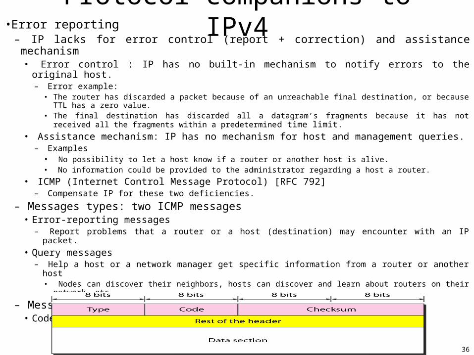
– Message format• Code: reason of the particular message type
37
Protocol companions to IPv4•Error reporting : ICMP (cont’d) •ICMP Error reporting
– ICMP simply reports errors to the original source • ICMP uses the IP source address, found in the datagram, to send the error message to the source
of the datagram.• The error message data section include the IP header of the original datagram plus the first 8
bytes of data in that datagram• The datagram header will give information about the datagram to the original source.• The first 8 bits of the datagram data contain the port numbers (TCP and UDP) and sequence number (TCP). The original
source can then inform the protocol (TCP or UDP) about the error. • An ICMP error packet is then encapsulated in an IP datagram => (ICMP lies just above IP)
– Five types of errors are handled• Destination unreachable -(ICMP Type=3, Code=0, 1, 2, 3)-
• Such a message is sent to the source host when a router cannot route the datagram or the destination host cannot deliver the datagram.
• Source quench -(ICMP Type=4, Code=0)-
• The lack of IP flow control could lead to congestion: the router/destination host is overwhelmed with datagrams.• When a router or the destination host discard a packet due to queue overflow (i.e. congestion), is sends such a message .• The source host knows that the datagram has been discarded and knows also that there is a congestion somewhere in the
path and that it should slow down (i.e. quench) the sending process.
• Time exceeded -(ICMP Type=11, Code=0)-• Such messages are generated in two cases: 1) by a router when a datagram is discarded because its TTL field is becomes
equal to 0 and 2) by a destination host when not all a datagram’s fragment arrive within a certain time limit.
• Parameter problems -(ICMP Type=12, Code=0)-• Such a message is sent by a router or a destination host when there is any syntax or semantic error in the datagram header
part.
• Redirection -(ICMP Type=5, Code=?)-• When a host sends a datagram, using its static routing table, to a wrong router, this router will forward (using a dynamic
routing table) the datagram to the correct router and will send such a message to this host to let it update its routing table.
38
Protocol companions to IPv4• Error reporting : ICMP (cont’d)
– ICMP Query• A node sends an ICMP query message that is answered in a specific format by the
destination node.• A query message is encapsulated in an IP datagram with no byte of the original IP
included.• Four types of querying messages
– Echo request and reply -(ICMP Type=8,0, Code=0)-• Echo-request and echo-reply are used to determine if two systems (hosts or routers) can communicate
with each other.• Because such messages are encapsulated with IP datagrams, the receipt of an echo-reply message by the
sender is a proof that the sender and the receiver can communicate using IP datagrams and that the intermediate routers are working.
– Timestamp request and reply -(ICMP Type=13, 14, Code=?)-• Timestamp request and timestamp reply messages are used to determine the round-trip time needed for an
IP to travel between two machines (hosts or routers).• Could also be used to synchronize the clock in two machines.
– Address-mask request and reply -(ICMP Type=17,18, Code=?)-• A host, that knows its IP address, wants to know the corresponding mask (to know its subnet address).• It then sends an address-mask request message directly to a router on the LAN (or using broadcast if
doesn’t know any router). • The router responds with an address-mask reply providing the necessary mask to the host.
– Router solicitation and advertisement -(ICMP Type=9, 10, Code=0,?)-• A host can broadcast (or multicast) a route-solicitation message to know the router(s) on its network. • The router (or routers) replies by router-advertisement message. Can help for the redirection messages?.• A router can also periodically send router-advertisement message even if no host has requested.
• The Ping and the Traceroute programs use ICMP messages to provide debugging Internet tools
39
Protocol companions to IPv4• Multicasting : IGMP
– IGMP (Internet Group Management Protocol) is one of the necessary (but not sufficient) protocols involved in multicasting.• Multicasting (vs. unicasting) is a one-to-many communications.
– Applications: travel agents can be informed simultaneously of a plane cancellation
– Group management• Multicast routers are able to route multicast packets.
– They use multicasting routing protocols.
• IGMP is a group management protocol (not a multicasting routing protocol).• IGMP provides multicast router with information about the membership status of hosts (routers) connected to the network.– It helps the router to create and update a list of loyal members to avoid broadcasting multicast packets creating a lot of traffic and consuming bandwidth.
– IGMP messages and message format• Three types of messages defined in IGMPv2
– 1) Query, 2) membership report, and 3) leave report.
40
Protocol companions to IPv4• Multicasting : IGMP (cont’d)
– Operation
41
Protocol companions to IPv6• ICMPv6
– Modified ICMP suited to IPv6.– ARP and IGMP are now part of ICMPv6.
• RARP has been dropped because it was rarely used and BOOTP has the same functionality.
– Error reporting• The source-quench message is eliminated.
– The priority and the flow label allow the router to control congestion and to discard the least important packet.
– No need to inform the sender to slow down.• Packet-too-big message is added
– The fragmentation is the responsibility of the sender in IPv6.– If the sender does not make the right packet size decision, the router drops the packet and
sends an error message to the sender.• Destination unreachable, time exceeded, parameter problem, and redirection
messages: same as with IPv4.– Query
• Two set of messages are eliminated– Timestamp query and reply messages and address-mask request and reply messages.
• Neighbor solicitation and advertisement messages are added– Was the duty of ARP in IPv4.
• Group membership messages are added– Was the duty of ICMP in IPv4.
• The remaining messages are the same as with IPv4.
42
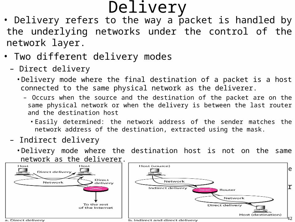
• Delivery refers to the way a packet is handled by the underlying networks under the control of the network layer.
• Two different delivery modes– Direct delivery
• Delivery mode where the final destination of a packet is a host connected to the same physical network as the deliverer.
– Occurs when the source and the destination of the packet are on the same physical network or when the delivery is between the last router and the destination host
• Easily determined: the network address of the sender matches the network address of the destination, extracted using the mask.
– Indirect delivery• Delivery mode where the destination host is not on the same network as the deliverer.
–The packet goes from router to router until it reaches the destination.
–A delivery always involves one direct delivery but zero or many indirect deliveries
Delivery
43
Forwarding• Forwarding means to place the packet in its route to its destination.
– Router forwarding : Choose the appropriate output interface for an incoming packet.
• Forwarding requires a host or a router to have a routing table.– An entry for every possible destination is impossible with the Internet.
• Forwarding techniques– Used to make the size of the routing table manageable (=> efficient lookup) and
also to handle issues such as security. – Three methods
• Next-hop method vs. route method– In the next-hop method, the routing table holds only the address of the next hop instead of the
information about the complete route (route method).
• Network-specific method vs. host-specific method– Instead of having an entry for every destination host connected to the same physical network
(host-specific method), the network-specific method uses only one entry that defines the address of the destination network itself.
• Default method – Define only one entry called the de default (normally network address 0.0.0.0), instead of
listing all the Internet’s networks, when there is only one path the rest of the Internet.
44
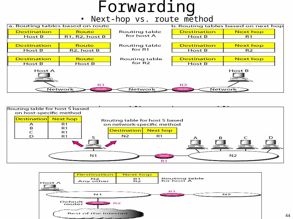
Forwarding• Next-hop vs. route method
• Network-specific vs. host-specific
• default
45
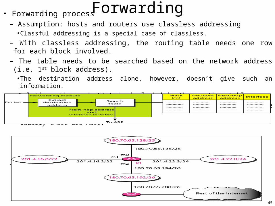
Forwarding• Forwarding process– Assumption: hosts and routers use classless addressing
• Classful addressing is a special case of classless.
– With classless addressing, the routing table needs one row for each block involved.
– The table needs to be searched based on the network address (i.e. 1st block address).• The destination address alone, however, doesn’t give such an information.
– Solution: the mask (/n) is included in the routing table
– With classless addressing, at least four columns compose the routing table• Usually there are more.
– Example
46
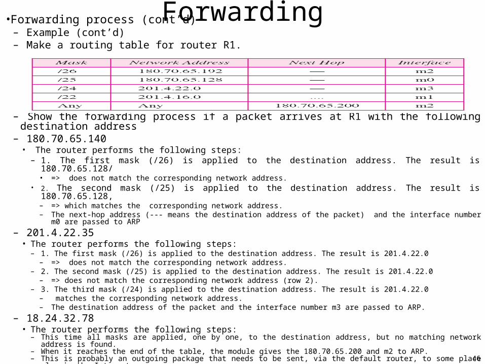
Forwarding•Forwarding process (cont’d)– Example (cont’d)– Make a routing table for router R1.
– Show the forwarding process if a packet arrives at R1 with the following destination address – 180.70.65.140
• The router performs the following steps:–1. The first mask (/26) is applied to the destination address. The result is 180.70.65.128/
• => does not match the corresponding network address.• 2. The second mask (/25) is applied to the destination address. The result is 180.70.65.128,
– => which matches the corresponding network address. – The next-hop address (--- means the destination address of the packet) and the interface number m0 are passed to ARP
– 201.4.22.35• The router performs the following steps:
– 1. The first mask (/26) is applied to the destination address. The result is 201.4.22.0– => does not match the corresponding network address.
– 2. The second mask (/25) is applied to the destination address. The result is 201.4.22.0– => does not match the corresponding network address (row 2).
– 3. The third mask (/24) is applied to the destination address. The result is 201.4.22.0– matches the corresponding network address. – The destination address of the packet and the interface number m3 are passed to ARP.
– 18.24.32.78• The router performs the following steps:
– This time all masks are applied, one by one, to the destination address, but no matching network address is found. – When it reaches the end of the table, the module gives the 180.70.65.200 and m2 to ARP. – This is probably an outgoing package that needs to be sent, via the default router, to some place else in the Internet.
47
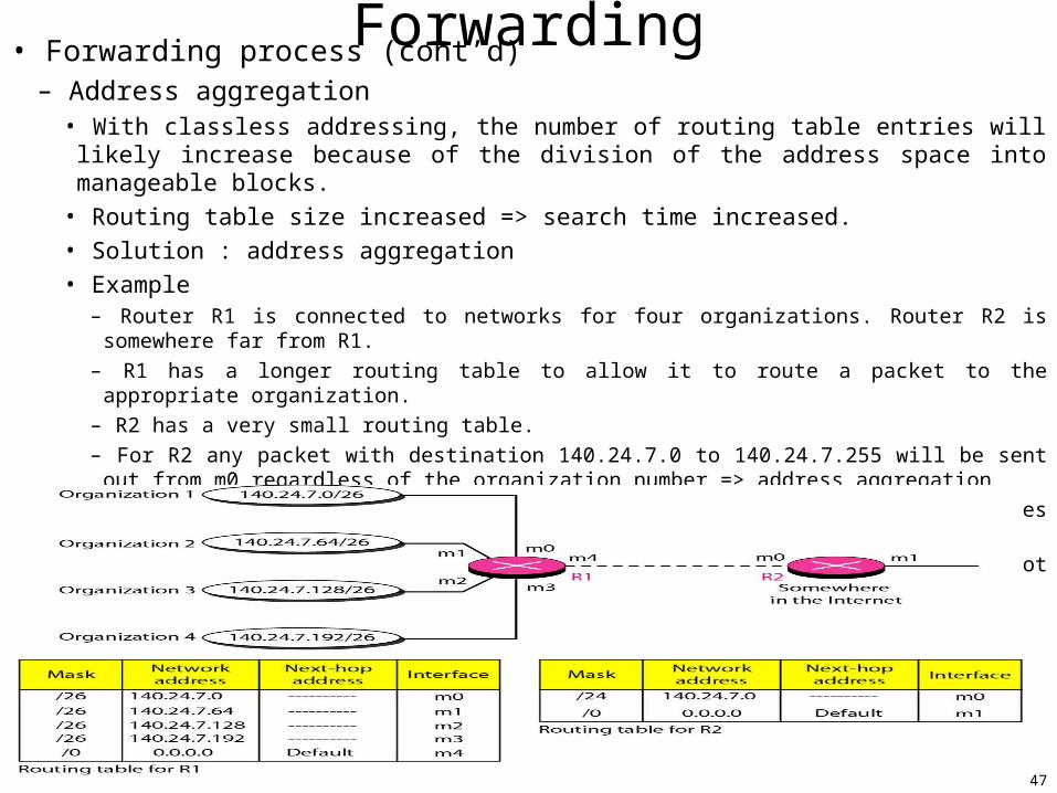
Forwarding• Forwarding process (cont’d)– Address aggregation
• With classless addressing, the number of routing table entries will likely increase because of the division of the address space into manageable blocks.
• Routing table size increased => search time increased.
• Solution : address aggregation
• Example– Router R1 is connected to networks for four organizations. Router R2 is somewhere far from R1.
– R1 has a longer routing table to allow it to route a packet to the appropriate organization.
– R2 has a very small routing table.
– For R2 any packet with destination 140.24.7.0 to 140.24.7.255 will be sent out from m0 regardless of the organization number => address aggregation
– This called address aggregation : the organizations’ blocks of addresses are aggregated into one larger block.
– Note : the network of each organization is independent (=> this is not subnetting).
48
Forwarding• Forwarding process (cont’d)
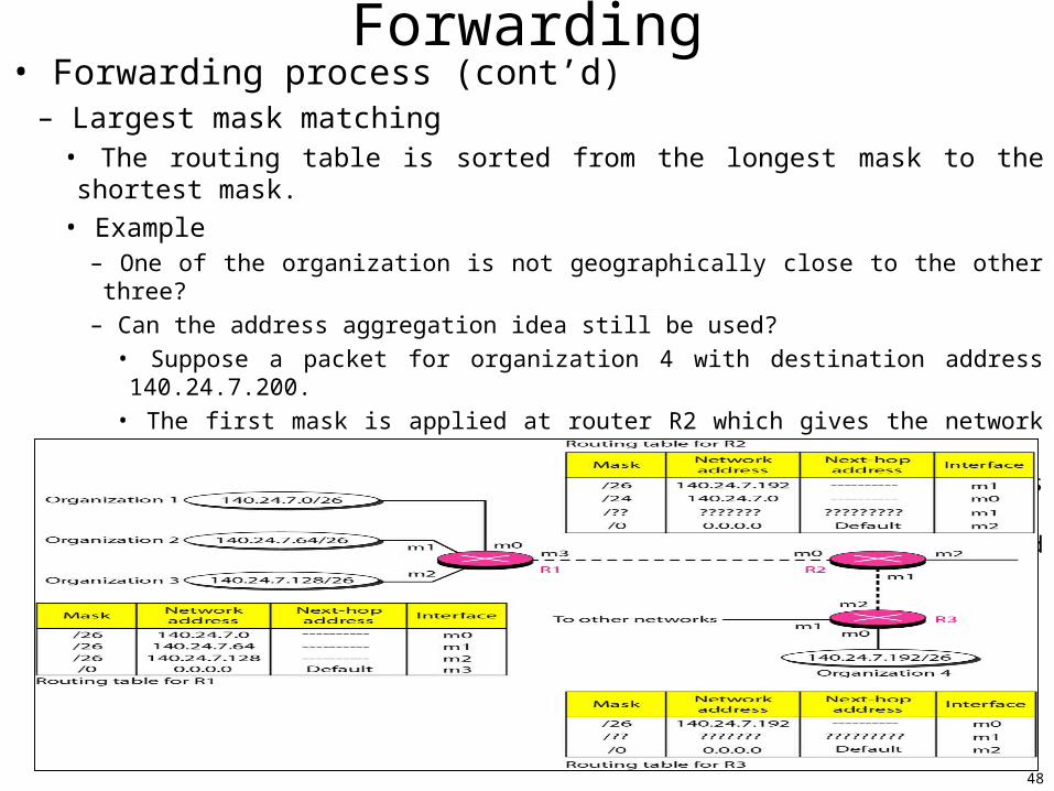
– Largest mask matching• The routing table is sorted from the longest mask to the shortest mask.
• Example– One of the organization is not geographically close to the other three?
– Can the address aggregation idea still be used?
• Suppose a packet for organization 4 with destination address 140.24.7.200.
• The first mask is applied at router R2 which gives the network address 140.24.7.192.
• The packet is routed correctly from interface m1 and reaches organization 4.
• If the routing table was not sorted, applying the /24 mask would result in the incorrect routing of the packet to router R1.
49
Forwarding• Forwarding process (cont’d)– Other ways to reduce the routing table size
• 1) Hierarchical routing, 2) Geographical routing– Routing table
• A router or a host has a routing table with an entry for each destination or a combination of destinations.
• Static routing table– Contains information entered and updated manually by an administrator.– Can be used in a small internet that does not change very often
• Dynamic routing table– Updated periodically using a dynamic routing protocol.– The routing protocols update the routers tables (eventually the host tables) automatically when there is a change
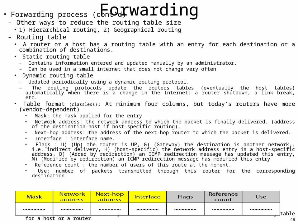
in the Internet: a router shutdown, a link break, etc.• Table format (classless): At minimum four columns, but today’s routers have more (vendor-dependent)
• Mask: the mask applied for the entry• Network address: the network address to which the packet is finally delivered. (address of the destination host
if host-specific routing).• Next-hop address: the address of the next-hop router to which the packet is delivered.• Interface : interface name.• Flags : U) (Up) the router is UP, G) (Gateway) the destination is another network,. i.e. indirect delivery, H)
(host-specific) the network address entry is a host-specific address, D) (Added by redirection) an ICMP redirection message has updated this entry, M) (Modified by redirection) an ICMP redirection message has modified this entry
• Reference count : the number of users of this route at the moment.• Use: number of packets transmitted through this router for the corresponding destination.
• Netstat is a Linux/Unix utility that can be used to find the content of a routing table for a host or a router
50
Routing protocols• Routing protocols created in response to the demand for dynamic routing tables.• A routing protocol is a combination of rules and procedures that lets routers in the internet inform each other of changes.
• Optimization– Usually a router is attached to several networks (i.e. many outgoing links). – Which of the available pathways (i.e. routes) is the optimum pathway for an incoming packet?–A cost (i.e. metric) is assigned for passing through a network. The metric depends on the type of protocol
• All the networks are equals.– I.e. the cost of passing a network is the same=one hop count.– EX.: RIP
• An administrator assigns a cost for passing through a network based on the type of service.– Maximum throughput=desired service type => a satellite link metric < optical fiber line metric.– EX.: OSPF allows each router to have several routing tables based on the required service type.
• The policy, set by an administrator, determines the metric– EX.: BGP
• Intra- and interdomain routing– An internet today can be so large that one routing protocol cannot handle the task of updating the routers’
routing tables.– => an internet is divided autonomous systems (ASs)
• An AS is a group of networks and routers under the authority of a single administrator.– Intradomain Routing : routing inside an AS.
• Each AS can choose one or more intradomain routing protocols.• Most popular: 1) distance vector, 2) link state.
– Interdomain Routing : routing between ASs.• Only one interdomain routing protocol is used between ASs.• Example: path vector.
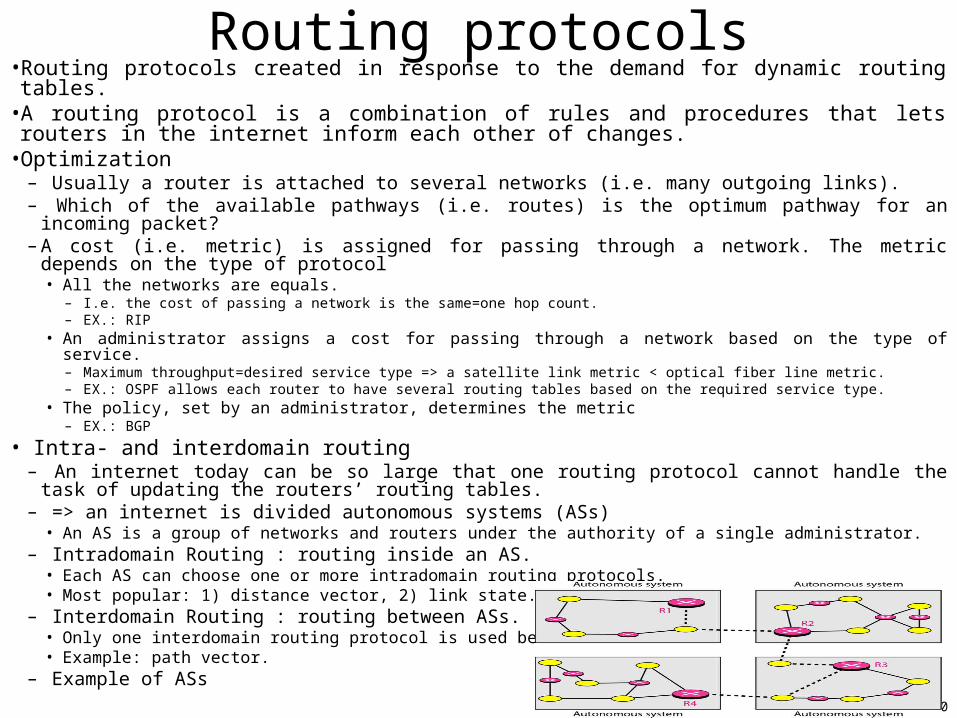
– Example of ASs
51
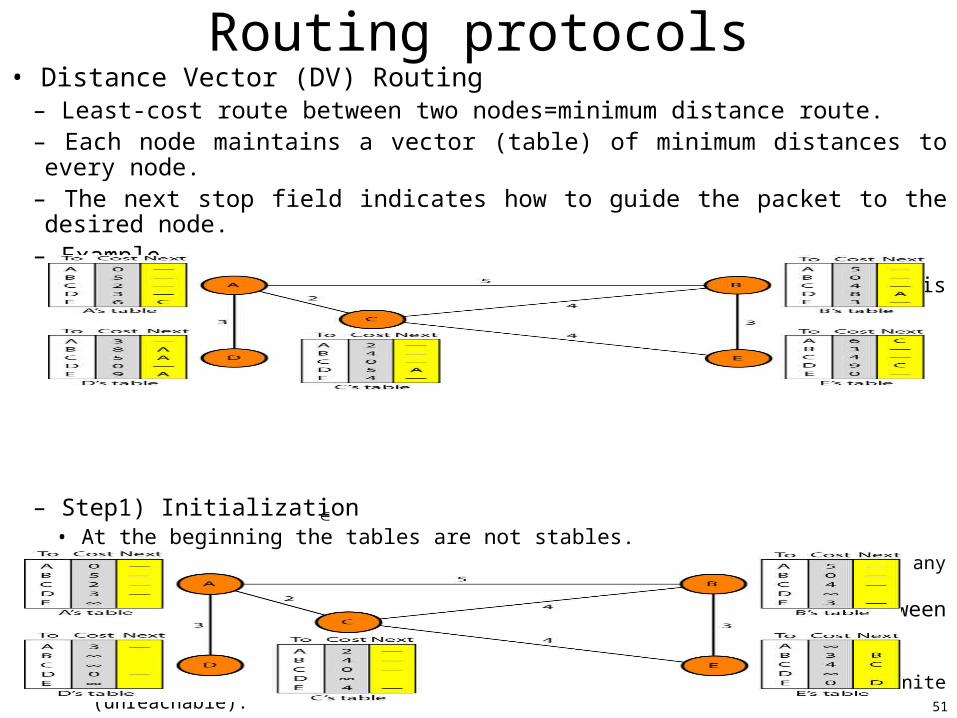
Routing protocols• Distance Vector (DV) Routing
– Least-cost route between two nodes=minimum distance route.– Each node maintains a vector (table) of minimum distances to every node. – The next stop field indicates how to guide the packet to the desired node.– Example
• The node A table indicates that the least cost to reach node E is 6 ; the route passes through C.
– Step1) Initialization• At the beginning the tables are not stables.
– The previous example's tables are stables: each node knows how to reach any other node and the cost.
• At initialization each node can know only the distance between itself and its immediate neighbors– An immediate node neighbor {nodes directly connected to it}– The distance for any entry that is not a neighbor is marked with infinite (unreachable).
52
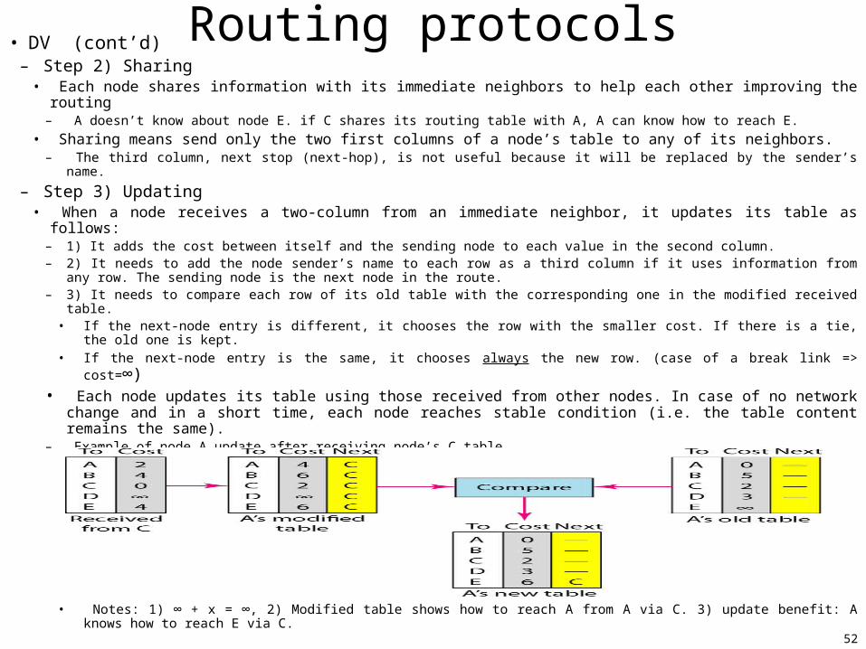
Routing protocols• DV (cont’d)– Step 2) Sharing
• Each node shares information with its immediate neighbors to help each other improving the routing– A doesn’t know about node E. if C shares its routing table with A, A can know how to reach E.
• Sharing means send only the two first columns of a node’s table to any of its neighbors.– The third column, next stop (next-hop), is not useful because it will be replaced by the sender’s name.
– Step 3) Updating• When a node receives a two-column from an immediate neighbor, it updates its table as follows:
– 1) It adds the cost between itself and the sending node to each value in the second column.– 2) It needs to add the node sender’s name to each row as a third column if it uses information from any row. The
sending node is the next node in the route.– 3) It needs to compare each row of its old table with the corresponding one in the modified received table.
• If the next-node entry is different, it chooses the row with the smaller cost. If there is a tie, the old one is kept.
• If the next-node entry is the same, it chooses always the new row. (case of a break link => cost=∞)• Each node updates its table using those received from other nodes. In case of no network change
and in a short time, each node reaches stable condition (i.e. the table content remains the same).– Example of node A update after receiving node’s C table.
• Notes: 1) ∞ + x = ∞, 2) Modified table shows how to reach A from A via C. 3) update benefit: A knows how to reach E via C.
53
Routing protocols• DV (cont’d)
– When to share?• Periodic update: a node sends its two-columns routing table periodically, normally every 30s.
– The period depends on the protocol using DV
• Triggered update: a node sends its two-columns routing table anytime there is a change in its routing table. i.e.– When a node updates its routing table after receiving a neighbor’s table.– When a node detects a failure in a neighboring link => distance= ∞
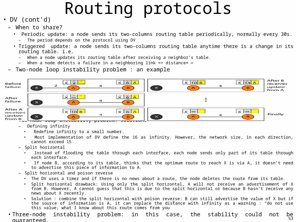
– Two-node loop instability problem : an example
• Two-node loop instability problem: solutions– Defining infinity
• Redefine infinity to a small number.• Most implementation of DV define the 16 as infinity. However, the network size, in each direction, cannot exceed 15
– Split horizontal• Instead of flooding the table through each interface, each node sends only part of its table through each interface.• If node B, according to its table, thinks that the optimum route to reach X is via A, it doesn’t need to advertise this piece of
information to A.– Split horizontal and poison reverse
• The DV uses a timer and if there is no news about a route, the node deletes the route from its table.• Split horizontal drawback: Using only the split horizontal, A will not receive an advertisement of X from B. However, A cannot
guess that this is due to the split horizontal or because B hasn’t receive any news about X recently. • Solution : combine the split horizontal with poison reverse: B can still advertise the value of X but if the source of information is
A, it can replace the distance with infinity as a warning : “do not use this value; what I know about this route comes from you”
• Three-node instability problem: in this case, the stability could not be guaranteed.
54
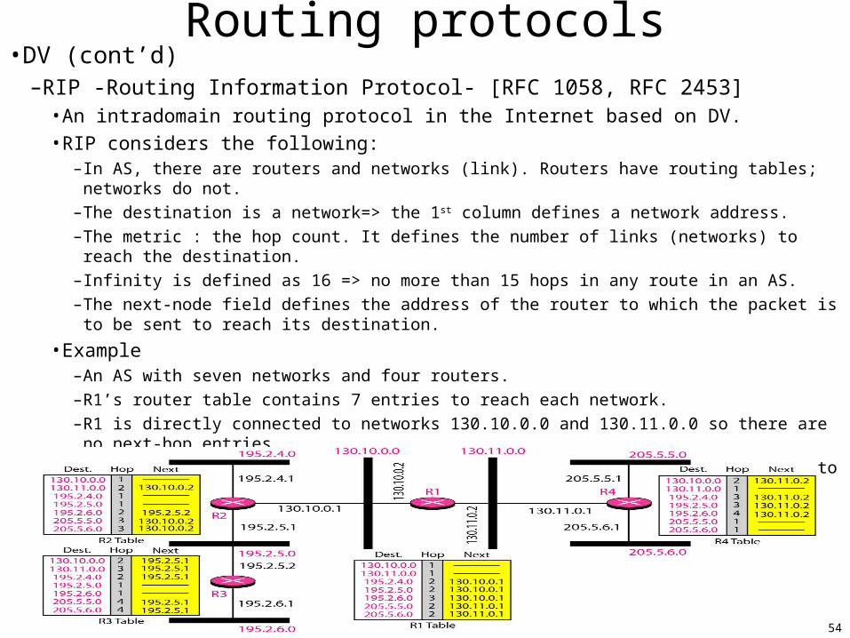
Routing protocols•DV (cont’d)
–RIP -Routing Information Protocol- [RFC 1058, RFC 2453]• An intradomain routing protocol in the Internet based on DV.
• RIP considers the following:– In AS, there are routers and networks (link). Routers have routing tables; networks do not.
– The destination is a network=> the 1st column defines a network address.
– The metric : the hop count. It defines the number of links (networks) to reach the destination.
– Infinity is defined as 16 => no more than 15 hops in any route in an AS.
– The next-node field defines the address of the router to which the packet is to be sent to reach its destination.
• Example– An AS with seven networks and four routers.
– R1’s router table contains 7 entries to reach each network.
– R1 is directly connected to networks 130.10.0.0 and 130.11.0.0 so there are no next-hop entries.
– To send a packet to one of the three left side networks, R1 needs to send to R2 through the interface with IP 130.10.0.1.
– To send a packet to one of the two right routers, R1 need to send to R4 through the interface with IP 130.11.0.1
55
Routing protocols• Link State (LS) Routing
– Each node in the domain knows the entire topology of the domain.– The topology must be dynamic.
• If there is any change in the network (ex. link down), the topology must be updated for each node.– Building routing tables: four sets of actions
• 1) Creation of link state packet (LSP), 2) Flooding of LSPs, 3) Formation of shortest path tree, 3) Calculation of the routing table from shortest path tree
– Creation LSP• Each mode creates LSPs• An LSP contains at least:
–1) node identity, 2) the list of links, 3) a sequence number, 4) age.– Items 1) and 2) to make the topology. Item 3) to distinguish new LSP from old ones. Item 4)
prevents old ISPs to remain in the domain for a long time.• LSPs are generated in two occasions:
–When there is a change in the topology of the domain.– On a periodic basis. The period is much longer than DV. Normally in the range 60mn to 2h.
– Flooding of LSPs• Means that the prepared LSP by a node is disseminated to all other nodes (not only its
neighbors).– The creating node sends a copy of LSP out of each interface.– The receiving node compares the LSP with the copy it may already have (based on the sequence
number). If the newly is older than the one it has, it discards it. Otherwise• Discards the old LSP and keeps the new one.• Sends a copy of it out of each interface except the one from which the packet arrived (i.e. guarantees that the flooding is stopped in the domain).
56
Routing protocols• LS (cont’d) – Formation of the least path tree : Dijkastra Algorithm
• A node will have a copy of the whole topology after receiving all the LSPs. • Need to create a shortest path three with that node as the root• Shortest path tree: a graph of nodes and links. There is a node called the root from where each other
node could be reached through only one single and shortest route.=> Use Dijkastra Algorithm.
• Example
57
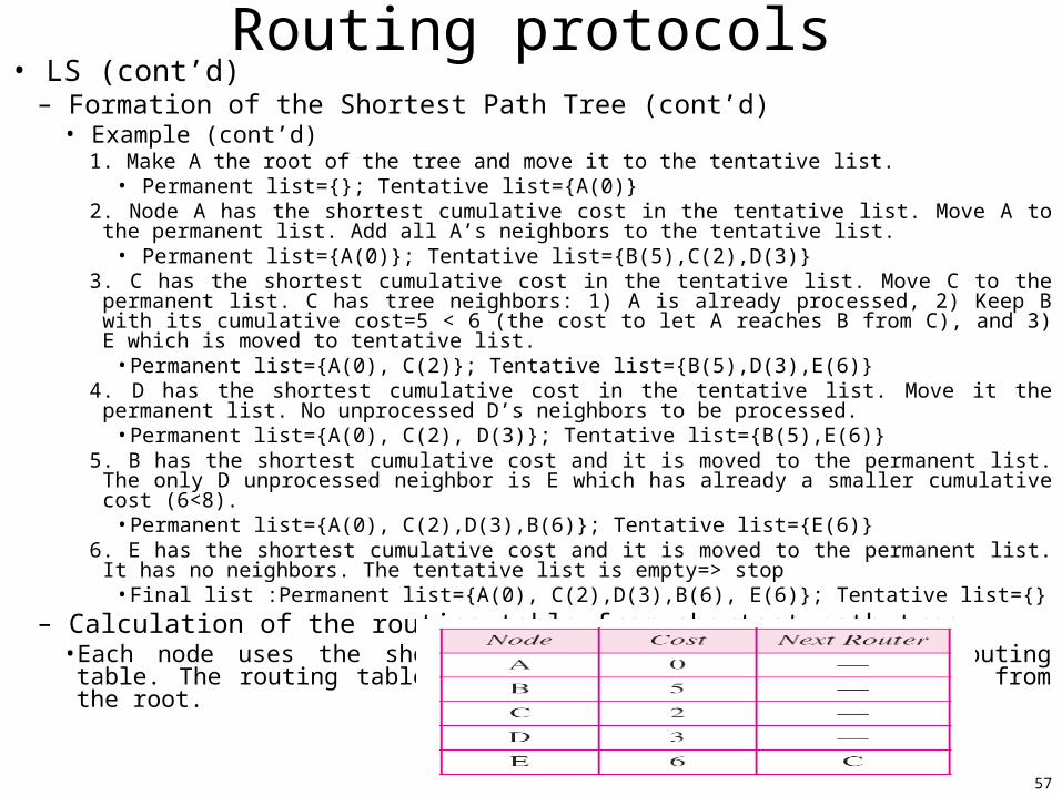
Routing protocols• LS (cont’d)
– Formation of the Shortest Path Tree (cont’d)• Example (cont’d)
1. Make A the root of the tree and move it to the tentative list.• Permanent list={}; Tentative list={A(0)}
2. Node A has the shortest cumulative cost in the tentative list. Move A to the permanent list. Add all A’s neighbors to the tentative list.
• Permanent list={A(0)}; Tentative list={B(5),C(2),D(3)} 3. C has the shortest cumulative cost in the tentative list. Move C to the permanent list. C has tree neighbors: 1) A
is already processed, 2) Keep B with its cumulative cost=5 < 6 (the cost to let A reaches B from C), and 3) E which is moved to tentative list.
• Permanent list={A(0), C(2)}; Tentative list={B(5),D(3),E(6)}4. D has the shortest cumulative cost in the tentative list. Move it the permanent list. No unprocessed D’s neighbors
to be processed.• Permanent list={A(0), C(2), D(3)}; Tentative list={B(5),E(6)}
5. B has the shortest cumulative cost and it is moved to the permanent list. The only D unprocessed neighbor is E which has already a smaller cumulative cost (6<8).
• Permanent list={A(0), C(2),D(3),B(6)}; Tentative list={E(6)}6. E has the shortest cumulative cost and it is moved to the permanent list. It has no neighbors. The tentative list is
empty=> stop• Final list :Permanent list={A(0), C(2),D(3),B(6), E(6)}; Tentative list={}
– Calculation of the routing table from shortest path tree• Each node uses the shortest path tree to construct its routing table. The routing table shows the cost of
reaching each node from the root.
58
Routing protocols• LS (cont’d)
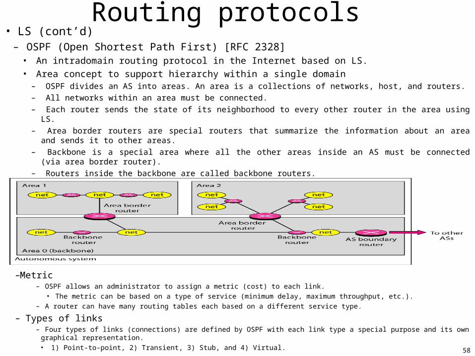
– OSPF (Open Shortest Path First) [RFC 2328]• An intradomain routing protocol in the Internet based on LS.
• Area concept to support hierarchy within a single domain– OSPF divides an AS into areas. An area is a collections of networks, host, and routers.
– All networks within an area must be connected.
– Each router sends the state of its neighborhood to every other router in the area using LS.
– Area border routers are special routers that summarize the information about an area and sends it to other areas.
– Backbone is a special area where all the other areas inside an AS must be connected (via area border router).
– Routers inside the backbone are called backbone routers.
– Each area has an identification. The backbone has the area 0.
–Metric– OSPF allows an administrator to assign a metric (cost) to each link.
• The metric can be based on a type of service (minimum delay, maximum throughput, etc.).
– A router can have many routing tables each based on a different service type.
– Types of links– Four types of links (connections) are defined by OSPF with each link type a special purpose and its own graphical representation.
• 1) Point-to-point, 2) Transient, 3) Stub, and 4) Virtual.
59
Routing protocols• Path Vector (PV) Routing
– DV and LS are not suited for interdomain routing because of scalability problem.• DV becomes instable if there are more than few hops in the domain• LS needs a huge amount of resources to calculate the routing tables.
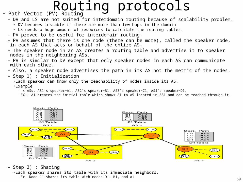
– PV proved to be useful for interdomain routing.– PV assumes that there is one node (there can be more), called the speaker node, in each AS that acts on
behalf of the entire AS.– The speaker node in an AS creates a routing table and advertise it to speaker nodes in the neighboring
ASs.– PV is similar to DV except that only speaker nodes in each AS can communicate with each other.– Also, a speaker node advertises the path in its AS not the metric of the nodes.– Step 1) : Initialization
• Each speaker can know only the reachability of nodes inside its AS.• Example
– 4 ASs. AS1’s speaker=A1, AS2’s speaker=B1, AS3’s speaker=C1, AS4’s speaker=D1.– EX.: A1 creates the initial table which shows A1 to A5 located in AS1 and can be reached through it.
– Step 2) : Sharing• Each speaker shares its table with its immediate neighbors.
– Ex: Node C1 shares its table with nodes D1, B1, and A1
60
Routing protocols• PV (cont’d)
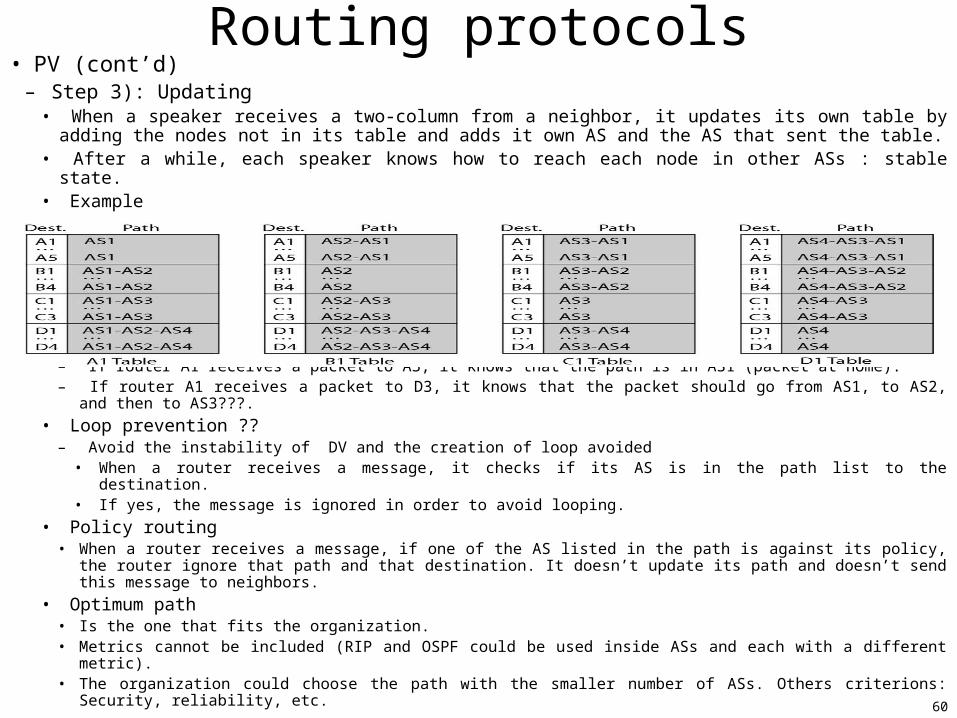
– Step 3): Updating• When a speaker receives a two-column from a neighbor, it updates its own table by adding the nodes
not in its table and adds it own AS and the AS that sent the table.• After a while, each speaker knows how to reach each node in other ASs : stable state.• Example
– If router A1 receives a packet to A3, it knows that the path is in AS1 (packet at home).– If router A1 receives a packet to D3, it knows that the packet should go from AS1, to AS2, and then to AS3???.
• Loop prevention ??– Avoid the instability of DV and the creation of loop avoided
• When a router receives a message, it checks if its AS is in the path list to the destination. • If yes, the message is ignored in order to avoid looping.
• Policy routing• When a router receives a message, if one of the AS listed in the path is against its policy, the router ignore that
path and that destination. It doesn’t update its path and doesn’t send this message to neighbors.
• Optimum path• Is the one that fits the organization.• Metrics cannot be included (RIP and OSPF could be used inside ASs and each with a different metric).• The organization could choose the path with the smaller number of ASs. Others criterions: Security, reliability,
etc.
61
Routing protocols• PV (cont’d)
– BGP (Border Gateway Protocol) [RFC 1772, RFC 1773, RFC 4271]• An interdomain routing protocol in the Internet using PV.
• AS types– 1) Stub AS, 2) multihomed AS, and 3) transit AS.
• Path attributes– A list of path attributes give some information about the path.
– Attribute category: 1) optimal attribute, and 2) well known attribute.
• BPG sessions– The exchange of routing information between two routers takes place in TCP session.
• Other routing protocol categories– All the routing protocol already presented fit into the unicast routing protocol
category.
– Other routing protocol categories• Broadcast routing protocols
• Multicast routing protocols – EX.: DVMPR –Distance Vector Multicast Routing Protocol.