Embed Size (px)
Citation preview

1. INTRODUCTION
The SMAES project is divided into three main technical work packages:
Experimental campaign This WP will provide necessary experimental data to support theother two work packages where existing data is inadequate or non-existent. It will alsoprovide key experimental data to support the two industrial demonstration cases.
Methods development for calculation of aircraft ditching loads. This WP is the first of thetwo primary research WP’s in the project. The main purpose of this WP is to extend existingsimulation tools for fluid behaviour to allow the effective calculation of fluid loads duringaircraft ditching. Expected outcomes are improved analytical and detailed modelsincorporating critical physical phenomena.
Dynamic structural behaviour under fluid loading. This WP is the second of the twoprimary research WP’s in the project. Its objective is to develop and demonstrate methods forthe investigation of aircraft structures under ditching loads. Expected outcomes of this WPare validated detailed methodologies to perform fluid structure coupled aircraft ditchingsimulations. Demonstrations of the methods on industrial test cases will be performed.
The main results from each work package will now be presented.
2. EXPERIMENTAL CAMPAIN
2.1. Guided Ditching Tests
The guided ditching test (GDT) was originally proposed in order to create a database for fluid-structure interaction problems at velocities representative of an actual aircraft ditching. As noexisting facility was capable of achieving the required conditions, the design, development andcommissioning of the experimental facility was completed under the SMAES project. This activitywas led by CNR-INSEAN where the facility was installed at one end of their towing tank. Other keypartners were Airbus Military, DLR and TUHH with the remaining partners contributing to thediscussion and to the definition of the experimental setup.
The activities completed in this task were:
Definition of test matrix and instrumentation for the GDT Design of the facility, trolleys and specimens Pretest simulations to support the facility and experimental design. Installation and commissioning of the facility Manufacture of composite plates Test execution Data collection and analysis
The design of the facility evolved during the project, with the final design capable of achievingimpact velocities up to 45m/s using a 750kg trolley. The commissioning of the guided impact facilitywas completed in June 2013, and the experimental programme began in July 2013.
To support the development of the facility, numerical simulations were carried out by TUHH, DLRand Airbus Military.

The ditching simulation method DITCH was used by TUHH to predict pressure and loads acting onplane and convex panels. The software tool VPS/PAM-CRASH was used by DLR and AirbusMilitary l to perform multiphysics simulations including fluid and structural dynamics.
Figures 1 and 2 show the facility as installed at one end of towing tank 1 at INSEAN. The facilityuses elastic ropes to accelerate the carriage, figure 3, prior to its impact with the water.
Two principal types of experiment we performed during the SMAES project using this facility:
Thick metallic plate – selected to minimise the deformation during impact and to ensure nopermanent deformation occurred. Flat plates as well as plates with positive and negativecurvature were tested.
Deformable plates – three plate designs were selected where large deformation and damagecould be expected. The three plates were an intermediate thickness metallic plate, a thinmetallic plate and a composite plate.
During the test programme a total of 47 tests were carried out using a thick metallic plate, with afurther 18 tests completed with deformable plates. The test conditions covered a horizontal velocityrange from 30-45 m/s, the vertical velocity was always set to 1.5 m/s. Varying impact from four toten degrees were used – this is the angle between the water surface and the initial plate surface.
An on-board data acquisition system was used to record the test data. The parameters that weremeasured were:
Accelerations – accelerometers mounted on the trolley Forces – the acquisition box was connected to the trolley by a total of six single axis load
cells allowing the longitudinal and vertical loads to be recorded. Strain – strain gauges were installed on all plates to monitor the plate deformation Pressures – pressure probes were installed on the plates to measure the local pressures
In addition high speed cameras were used to film the tests, figure 4, and a non-contact optical tensorwas used to monitor the velocity and displacement of the trolley. Prior to the curved panel tests anunderwater camera was installed to record the impact from below, figure 5. This camera can showregions of air entrapment or cavitation and help understand the other experimental measurements.
One main concern prior to the experimental campaign was the test-to-test dispersion, as throughoutthe test program it was not feasible to repeat each test condition more than three times whichrequired a certain level of confidence. Two series of test-to-test dispersion experiments wereconsequently included in the test programme. Analysis of the results from these two cases shows ahigh level of repeatability. This can be seen in figure 6 where strain and force curves for all 10repeats of the 4° pitch experiments are plotted together. In addition the competed tests have shownthat the facility provides good repeatability for the carriage impact velocity.
The test results are also showing some interesting flow features, including negative pressures seenfor the 10° pitch case, figure 7. This negative pressure occurs before the sharp rise in the signal, witheach probe showing the same pressure level but with an increased duration along the plate.
Due to the high level of repeatability achieved in the tests, it was decided to run only a single casefor certain deformable plate conditions in order to allow a an extra test condition of 45 m/s with 10°pitch angle to provide a broader data set. No rupture occurred during any of the tests, althoughsignificant permanent deformation occurred with the thin (0.8mm) aluminium plate.
For the composite panels no visible damage occurred during the tests, although a small amount ofpermanent defamation was measured with the plate mounted on the test frame. The tested compositeplates were removed and delivered to DLR for post-test inspection, as there was no visible damagethe plate tested at the most severe impact condition was selected for further analysis as the test data
showed this panel had experienced the highest level of strain during the test. An ultrasoundinspection in the region of greatest strain showed that the material remained homogenous, indicatingno significant damage. The panel was then sectioned and two locations were selected forinvestigation using computer tomography (CT). No delamination or damage was found in the CTinspection.
Following the successful drop test on the structural sub-component specimen at ONERA (see thenext section), it was agreed that the second specimen would be adapted and tested at the CNR-INSEAN facility, with support from Dassault Aviation. The specimen instrumentation remainedunchanged and the specimen mounting was adapted to fit the GDT trolley. The agreed test conditionwas 40m/s horizontal velocity, 2m/s vertical and 6 degree pitch angle. The test under theseconditions was completed successfully. As the specimen remained essentially intact, it was judgedsafe to perform a second test at the same velocity but with the pitch angle increased to 9 degree.During this test the skin ruptured.
2.2. Experiments in support of Dassault Test Case
The experimental programme in support of the Dassault test case was aimed at characterising basicstructural elements and component materials under dynamic loading. The partners mainly involvedin this task are Dassault Aviation, ONERA and the University of Patras.
Early in the SMAES project a common composite material, AS4/8552, was selected as the onlycomposite material to be used within the SMAES project. This permitted the results from thematerial characterisation experiments to be combined onto a single larger database for use insimulations of all the experiments on composite specimens.
2.2.1. Material characterisation programme
The material characterisation programme in support of the Dassault test case was carried out by theUniversity of Patras. The test programme included both static and dynamic tests on compositespecimens for the following conditions:
Tension Compression Inter-laminar strength Filled –hole Tension Filled –hole Compression Bearing Strength Pull – out (pure tension) Pull – out (tension & bending)
All tests were performed using specimens of AS4/8552 158gsm material with [45/90/-45/0/45/90/-45/0]s or [45/90/-45/0/45/90/-45/0]2s stacking sequence. Several different strain-loading rates wereapplied per test, ranging from static to medium strain rate. As there are no available standards for thetype of dynamic tests or samples, industrial specifications or respective standards from the relativestatic tests were been used. Dynamic tests were performed using a Split Hopkinson Pressure bar(SHPB) apparatus with some modifications in order to grip the composite specimens, as well as aDrop Tower machine. Special fixtures and jigs were specially designed, manufactured and adapted tothe Drop Tower in order to test coupons and riveted specimens in tension, compression, shear,bending and bearing. Static tests were conducted in a servo-hydraulic test machine
Nine different composite AS4/8552 specimen configurations, ranging from simple modulus couponsto simple and complex riveted configurations were tested in various loading rates i.e. from static to

4m/sec, corresponding to strain rates from static to 2500s-1. The load and the displacement fieldwere accurately measured with the use of a high precision piezoelectric load cell, as well as acontactless displacement transducer integrated with the Digital Image Correlation technique. Thespecimen strength was determined and the individual failure modes were examined for all of thetested samples. Strain rate sensitivity, concerning the failure load, was observed for coupons whichwere dominated by delamination failures (i.e. Modulus Compression, Pull-Out, Pull-Out & Bending)while slight or insignificant strain rate sensitivity was observed for the specimen which failed mainlyin fiber tension breakage mode (i.e. Modulus Tension, Filled-Hole Tension, Bearing).
2.2.2. Structural characterisation programme
The overall objective of this experimental programme was to characterise the basic structuralelements and component of the Dassault test case under static and dynamic loading. ONERAdeveloped the experimental devices to test two kind of assembly component to be tested using theexisting “crash tower” facility, figure 8, and a standard static compression machine.
A panel design was developed for this project representative of a hybrid metallic-composite businessjet fuselage structure. The panel consisted of a composite skin riveted to metallic frames andstiffeners.
Three types of test were developed and performed within the project:
The first two tests were static tests on a single frame and associated skin, with the purpose ofproviding data to support the development of structural models.
The third type of test was a dynamic test on an entire panel assembly with the loadingprovided by a honeycomb block of calibrated crush stiffness.
The honeycomb block was designed to reproduce the dynamic loading and the rapid growth of thewetted area, and to provide a well characterised distributed load over the surface of the panel.
Two drop tests were performed. The first test used the design pressure load and caused no damageto the structure. The second test applied a higher load designed to destroy the structure and resultedin the symmetrical collapse of the structure.
Following this successful test using the first panel specimen it was decided that the second specimenshould be tested using the new facility at CNR-INSEAN as previously discussed.
2.3. Experimental programme in support of the Alenia Test Case
The experimental programme in support of the Alenia test case was aimed at characterising basicstructural elements and component materials under dynamic loading. The partners mainly involvedin this task were Alenia and CIRA.
2.3.1. Material characterisation programme
The material characterisation programme in support of the Alenia test case was carried out by CIRA.The test programme covered static tests in tension, compression and shear and dynamic tension testsof specimens with different layups. All tests were performed using specimens of AS4/8552.
All static tests were successfully completed. Due to a failure in the high-rate test machine at CIRA,the dynamic tests were completed by the University of Patras in their drop tower facility.
2.3.2. Structural characterisation programme
The overall objective of this experimental programme was to test structural element with simpleshape under water impact. The test facility consists of a 11 m height steel drop tower, figure 9, which

is able to guide the descent of a trolley which brings the test article. Another trolley is sitting at thetower footing and can be raised after testing to recover the test article and the trolley.
The test article is a semi-cylindrical shape, with the skin of the test stiffened by three frames, figure10. The skin is made of CFRP, with two layups for the skin investigated. Four test articles have beenmanufactured two for each layup. A total of eight drop tests were completed, four at low velocitywhere damage did not occur and four at higher velocity resulting in specimen damage.
2.4. Conclusions
The main results and achievements of the SMAES experimental campaign are:
Development of the guided ditching test facility. This facility provides a new capability forhigh velocity/low impact angle water impact experiments to support future research anddevelopment in water impact response.
Guided ditching test database. A total of 65 tests were completed during the SMAESprogramme. This proves a high quality database of test results to support futuredevelopments in water impact analysis. The test conditions achieved significantly extend therange of conditions for which experimental data is available to researchers.
Structural element test data for the Dassault and Alenia test specimens providing results forthe response of composite structures to water impact. Including a range of test conditionscovering tests without failure and tests with failure makes possible the validation of structuralmodels suitable for failure prediction.
Material characterisation tests database to provide material data suitable for modelling allcomposite test specimens.
3. METHODS DEVELOPMENT FOR CALCULATION OF AIRCRAFT DITCHINGLOADS.
3.1. Semi-analytical models
The objective of this work was the extension and development of semi-analytical methods for thecalculation of fluid loads. Semi-analytical methods are developed from techniques used in navalhydrodynamics and use analytical models modified where appropriate by empirical factors. Theirspecific advantage is their low computational cost. This makes these approaches well suited to earlystage design calculations as well as parametric studies.
The University of East Anglia developed a new semi-analytical approach for the prediction ofhydrodynamic loads acting on an aircraft during a ditching event based on the Modified LogvinovichModel. This method is based on a 2D+t approach which makes it possible to reduce the three-dimensional (3D) oblique impact problem to a sequence of two-dimensional (2D) vertical waterentry and exit problems. Such an approach is widely used in the ship industry for the study ofplaning hulls. However, this approach has been so far mainly applied to prismatic hulls (V-shapes)and needed to be adapted to the ditching problem. In addition the unsteady flow problem has beenvery little investigated. Therefore, the 2D impact problem has been formulated for a 2D body shapeof which is changing in time and the Modified Logvinovich Model (MLM) has been adapted in orderto deal with such an impact. The flow is studied from the point of view of vertical planes fixed in theglobal coordinate system (control planes) through which the three-dimensional body is passing, anexample is shown in figure 1. As the body moves through the control planes the body first enters the

water and then exits the water. During the exit stage, the classical Wagner approach, and thus theMLM, is no longer valid. The 2D+t approach represents water exit effects at the rear of the fuselageusing a von Karman–type model consistent with the MLM. This approach was validated for a rangeof 2D and 3D test cases. The MLM approach has been implemented within the industrial ELFINIcode.
3.2. Detailed methods – improved numerical efficiency
The objective of this task was the development of improved algorithms and methodologies for themeshless and Euler methods in order to reduce the required computational time of ditching analyses.The high forward velocity in ditching requires potentially large fluid domains, requiring the use ofsignificant computational resources to perform an analysis.
Two numerical approaches were used within SMAES:
The Coupled Euler Lagrange (CEL) method – fluid is modelled using an Euler/ALE mesh Meshless approach – fluid is modelled using Smoothed Particle Hydrodynamics (SPH)
method.
Both methods are well established in commercial analysis codes and both have previously beenapplied to water impact and ditching analysis.
In the CEL method the fluid domain (the water and air) are modelled using a numerical meshindependent of the structure. The interaction of the fluid and the structure is modelled through aspecific interface that enforces the contact condition, ensuring there is no penetration of the fluidthrough the structure. The following principal developments were made to the CEL capability
Fluid mesh moves with the structure Inlets / outlets Improved CEL interface
The benefit of the first two developments is that the size of the fluid domain can be reduced, andconsequently the overall computational cost of an analysis is reduced. This is achieved by linkingthe motion of the fluid mesh to the structure. Inlet and outlet conditions are placed on all theboundaries of the fluid mesh to allow correct treatment of the entry and exit of the water and air forthe fluid domain. Studies using the established contact interface have shown key limitationsincluding: Sensitivity of the simulation results to user input values; the requirement that the fluidmesh must be fine enough to follow the geometry of the structure, this is a limitation at the tail of anaircraft fuselage; diffusion of fluid material through the structure; oscillation of the contact force onthe structure. An improved fluid structure interface algorithm where the fluid elements are splitfollowing the geometry of the structural elements was developed, allowing the interface pressure tobe computed independently in each zone. A challenge with this approach is efficiently and robustlydealing with the many different topologies that can be generated with this approach.
For the meshless SPH method the following principal developments were made
New Particle SPH re-distribution algorithm (including merging) Damping zone to avoid reflecting waves Density/pressure correction Weighted Voronoi Tesselation for initial particle distribution
The objective of the particle redistribution is to allow particle positions to be changed during thesimulation in order to keep the distribution more uniform. The algorithm also allows for the creationand removal of particles during an analysis. The algorithm has been demonstrated for 2D problemsand has resulted in a much more regular particle distribution in the case when a particle has an
irregular spacing with its direct neighbours. The first-order correction of relevant SPH properties inthe displacement correction conserves mass and momentum, and ensures that local properties such asdensity and velocity remain smooth. This approach reduces or eliminates the known ‘clumping’tendency of SPH.
The use of a damping zone to avoid wave reflection is being investigated by both ESI and Cranfield.Reducing the size of the fluid domain reduces the overall computational cost of an analysis, but if theboundaries are too close to the structure, their presence changes the fluid behaviour and the structuralloading becomes inaccurate. The objective of the damping zone is a boundary condition that absorbssurface waves, preventing their reflection from the boundary. .
One of the well-known drawbacks of the WC-SPH solution as discussed above is the rather largevariation in pressure, both in time and space. A modified equation for the new density containing apressure correction has been implemented by ESI, and a density smoothing algorithm wasimplemented by Cranfield. Both corrections provide a significantly smoother pressure distributionthan the reference SPH simulation but without notable effects on the free surface location andvelocities. The total fluid volume (or average density) is also not modified.
ESI have also implemented a modified version of the Weighted Voronoi Tessellation (WVT) methodto address the known shortcoming of the standard SPH approach in employing a non-uniformvolume discretization algorithm for iteratively improving a particle distribution for filling a givenvolume starting from a simple particle distribution located somewhere inside the volume. Thisalgorithm is useful for generating configurations of particles with spatial variations to simulate localphenomena in large (fluid) domains i.e. water entry, ditching and flow around submerged objects.The algorithm is also useful for generation of initial particle distributions of good quality withincomplex geometries and with free surfaces. Use of the algorithm ensures that the final particledistribution is of sufficient quality.
3.3. Modelling of Complex Flow Physics
The objective of this task is to extend current fluid modelling approaches where existing physicsmodels do not include all important physical phenomena. Previous work, including the FP5 projectsCRAHVI and CAST, have shown good correlation with experiments for detailed numericalsimulations applied to vertical and near vertical impacts. When these analysis tools have beenextended to ditching of fixed wing aircraft good correlation has not been seen. One of the identifiedcauses has been the use of simplified fluid models that do not capture all the important physicalphenomena that occur in high speed flow past a structure. Specific issues identified are
Air cushioning Ventilation Cavitation Suction force
The work performed in this task is aimed at improving the capability of all the numerical approachesto accurately represent key aspects of the fluid behaviour.
For the semi-analytical methods, TUHH has extended the DITCH code to include the effects ofaerated water. For adequate combinations of forward velocities, pitch angles and deadrise angles airmight be sucked underneath the aircraft fuselage in the front and induce air-cushioning effects duringan aircraft ditching. The air bubbles and ambient water also form a mixture with characteristicphysical properties according to the water/air volumetric concentration. The addition of aeration

leads to significantly deeper immersion and further modifications were required to account for deepimmersion effects. A modified pressure limit model was introduced to represent ventilation.
Models for flow separation and the treatment of suction during the exit phase were incorporatedwithin the MLM model resulting in improved agreement with CFD results.
For the SPH method cavitation and aeration were treated through the extension of the existing single-phase fluid model to a two-phase model to represent the behaviour of a mixture of gas and water.This model assumes that the material represented by a particle is a mixture of gas and water asbubbly flow with bubble sizes small compared to the characteristic particle length. Additionally thisapproach assumes that the total mass of each particle is constant (consistent with the SPH method)and consequently that the velocity of both phases is constant. For aeration an equation of state forthe air fraction s required within the model formulation. For cavitation a model that allows thetransfer of mass between the liquid and gas phases in a particle is required and different options wereinvestigated.
For the CEL method improvements to the treatment of cavitation and ventilation effects were alsomade.
3.4. Validation studies
The objective of this task was to provide validation and verification of the developments to thenumerical methods and models for the water through the analysis of a common set of test problems,with additional test problems used by specific partners where appropriate. The test problems did notcover cases where structural flexibility is important as this is covered within the ‘Dynamic structuralbehaviour under fluid loading’ work package.
Two common test problems were selected:
The NACA 2929 configuration J model ditching test Three impact cases from the INSEAN guided ditching test programme.
The NACA 2929 case uses body configuration J from the NACA-TN-2929 report. This was selectedto allow testing of the overall dynamics of a ditching aircraft, not possible with the INSEANexperiments. The report gives results for rigid model tests at different initial velocities. This casewas modelled with all methods. The semi-analytical models showed good agreement with thepublished data, see figure 11 for an example. The CEL method also showed the ability to predict theoverall motion, see figure 12, with improved agreement at lower velocities. The SPH method waslimited by its ability to capture the suction force. Without the suction force the initial pitch upmotion is not predicted, an approach to mimic the suction force through the contact algorithm in theVPS SPH code did show the ability to model the initial increase in pitch angle.
Semi-analytical, SPH and CEL models of the guided ditching tests were also successfully completed.As the semi-analytical approach is not applicable to a flat plate they must assume a finite radius ofcurvature or dead-rise angle to approximate the experimental results. The results showed the abilityof these methods to predict the overall force and local pressure results. Examples of SPH results(DLR) are shown in figure 13. The SPH method is capable of good correlation both for force andstrain results, showing that structural loads are accurately captured. The method does not include aseparate air model, consequently air entrapment not correctly treated.
Examples of CEL results (ONERA) are shown in figure 14. In general the CEL captured thetimeline and the early stage structural loading correctly. While the pressure and strain profiles werereasonable the peak values were low due to the FSI interface algorithm and the plate meshresolution.

During the Airbus Military CN235 ditching certification a test campaign was performed with asubscale rigid mock-up. A reference test case corresponds to 14 m/s and 8 degrees pitch angle wasselected for the SMAES project. A numerical model of the CN235 rigid mock-up has been preparedin the VPS code. The numerical model of the water block consists of SPH particles and an externalblock of classical continuum finite elements to reduce the computational effort. This model includesa simplified model for the aerodynamic forces using a user subroutine.
Figure 15 shows the impact sequence for the Airbus Military CN235 subscale rigid model. Theimpact occurs at the rear fuselage and the mock-up slightly nose-up. The contact algorithm in theVPS code allows a separation stress to be defined, resulting in particles remaining attached to thestructure. This mimics the suction effect providing a realistic nose-up effect observed in ditchingtests. Figure 16 demonstrates that inclusion of suction is essential for a correct prediction of theaircraft trajectory.
In the FP5 CRAHVI project both DLR and ONERA developed ditching models of the A321 aircraft,DLR using PAMCRASH and ONERA using RADIOSS. Within SMAES, DLR and ONERAupdated and reran these models using SPH fluid models. The ONERA model was also adapted forthe CEL fluid model and run successfully for a range of impact conditions. This model was thenused as the basis for a deformable structural model.
3.5. Conclusions
The main results and achievements of the methods development work are:
Development of a novel semi-analytical method for the prediction of hydrodynamic loadsacting on an aircraft during a ditching event based on the Modified Logvinovich Model.
Improvement to both the Coupled-Euler-Lagrange and Smoothed Particle Hydrodynamicsdetailed methods that reduce the computational cost of the fluid element of the ditchingmodel.
Improvements to the physics models for the water for all numerical methods. In particularthe treatment of aerated water in the semi-analytical and SPH methods and the treatment ofcavitation in the SPH method.
Analysis of results from the improved semi-analytical, SPH and CEL fluid models show that,correctly used, they are all capable of accurately capturing the structural loads duringditching.
4. DYNAMIC STRUCTURAL BEHAVIOUR UNDER FLUID LOADING.
4.1. : Ditching adapted structural models
The objective of this task was the development of simulation models and methodologies relevant inthe application of coupled ditching simulations. The main challenge for ditching structural models isintegrating the effect of complex local phenomena occurring at the location of impact within globalaircraft models.
The University of Patras concentrated on the development of macro models for bolted joints that canbe used in structural simulations based on very detailed local 3D models, and a macro-elementapproach to link structural level analyses to coupon scale characterisation tests for compositematerials. Macro models allow the treatment of local phenomena in large component or full aircraftstructural models.

Development by Alenia and Dassault concentrated on adapting current structural models to theditching analyses methodologies developed and including the ability to predict structural failure andrupture.
4.2. Fluid-structure interaction
The objectives of this task were
Integration of the new fluid models developed with deformable structural models. Improvements to fluid model – structure model interaction methodologies Validation of improved codes on common test cases
Hybrid aircraft models based on beam elements to model the overall aircraft flexibility wereintegrated with the semi-analytical fluid models. These simplified structural models are generated bycondensation of a detailed FE model to obtain the generalised mass and stiffness properties.
As the numerical methods considering a full representation of a deformable aircraft in fine meshedFE techniques require a lot of calculation time, further methods to speed up the simulations areinvestigated. One promising candidate for a strong reduction of calculation time is the coupling ofdifferent models / domains that can be solved at different time steps. In this method a proper overallsolution has to be guaranteed by frequent interaction of the models / domains using adequate contactinterfaces. This approach was investigated for both the CEL and SPH methods when coupled with astructural model. Test problems were successfully analysed that showed a decrease in calculationtime with no change to the model accuracy.
Besides development and demonstration of improved fluid structure models the validation of thesenew numerical tools was a major objective in this task. The primary test cases used for this were theguided ditching test experiments with deformable plates, with some partners additionally usingpurely numerical full scale aircraft studies.
Detailed guided ditching test (GDT) simulations have been carried out by several partners, with thefinal models for the flexible plate simulations shown in figure 17. Some refinements have beenrequired over the thick plate models to improve the deformable plate models.
Results for the SPH and CEL methods show that both approaches are capable of good agreementwith experimental results for overall trolley behaviour and plate response. The strain response in themodels was best for gauges mounted away from the plate boundaries. The correlation withexperimental results for gauges near the plate boundary was affected by the large strain gradientsnear the boundaries, which made it difficult to capture the strain distribution at the exact gaugepositions.
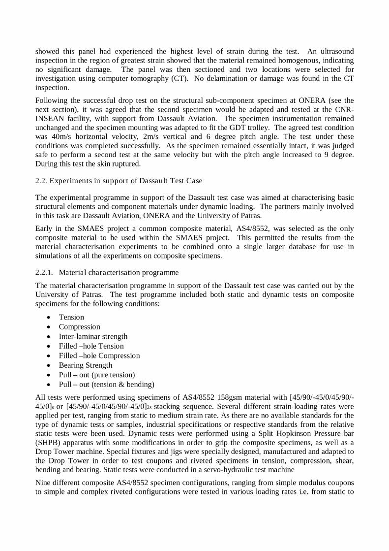
A visual comparison of DLR simulation results for a 3mm plate with experimental video, figure 18,shows good agreement. The initially flat panel deforms and the resulting curvature is similar to thatof the concave panel test case.
ONERA updated their deformable A321 model to run with a CEL fluid model in the same manner asdone for the rigid model. As it was not possible to use the mass scaling approach in this analysis,only the early stages of the impact could be successfully analysed as a run time of approximately oneyear would have been required, using the development version of the code available, to reach 5s ofsimulation time.
DLR developed a generic single aisle transport aircraft model to be used for ditching analysis. Thismodel uses the DLR in-house tool TRAFUMO (Transport Aircraft Fuselage Model) to generateglobal FEM models of a transport aircraft fuselage based on a standardized data format CPACS

(Common Parameterized Aircraft Configuration Schema). The TRAFUMO fuselage model iscombined with a wing model developed using the DLR ELWIS tool. In general, TRAFUMO allowsthe modeling of an aircraft fuselage outer surface based on cross section definitions, which form asmooth outer surface using a public domain CAD kernel. This surface is discretized using shellelements. The internal support framework of the skin, such as stringers and frames, are modeledusing beam elements, which share common nodes with the skin. For the stringer and frame profilesarbitrary cross-section may be defined in the CPACS definition. Finally the floor structure, modeledwith beam elements, and the bulkheads using shells and beams are added.
Three aircraft modelling approaches were investigated using the generic single aisle model. Thesimplest one is a rigid body model, which is a derivative of the full flexible fuselage model that onlycontains the outer shell (skin) to provide the outer shape of the fuselage. An intermediate modelvariant, referred to as the dynamic aircraft model, was also developed. This model uses beamelements to represent the global stiffness of the fuselage linked to rigid sections that represent thefuselage geometry. All three variants were successfully analysed with an SPH water model. Thebehaviour of the RBM and DAM approaches was similar, however structural deformation in theDFEM model changes the contact force significantly.
4.3. Industrial test cases
4.3.1. Dassault test case
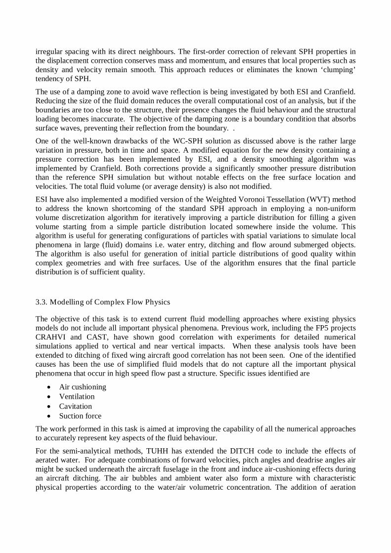
This test case uses a structural concept for a lower rear fuselage section consisting of composite skinwith a metallic supporting structure. This test case represents a ditching scenario of a genericFALCON business jet and is extracted from already certified business jet programme to provide aconsistent test case.
Based on ditching conditions presented above and standard sizing procedures, a representative paneldesign with a composite skin and metallic frames and stringers was developed and representativecomponents were manufactured under the experimental work package. In figure 19 a model of arepresentative aft fuselage shape used for this test case and a test panel extracted from the aftfuselage design are presented.
Both semi-analytical and detailed methods were used to analyse the overall ditching behaviour of theaircraft. Detailed models of the two static structural element tests performed by ONERA and therepresentative panel tests at ONERA and CNR-INSEAN were developed. The models show goodagreement with experiment for global behaviour, buckling loads, rupture modes and strain readings.The complex failure mechanisms that occur under dynamic load, combing failure in metallic andcomposite materials as well as rivet failure remain a challenge for analysis codes.
The Dassault test case shows how numerical analysis can be efficiently integrated into the aircraftdesign procedure for ditching through the use of two different hydrodynamic load simulations andstructural deformation models to achieve precise objectives.
The coupling of the analytical method and the macro-scale model is an efficient strategy (lowcomputational cost) to have access to the global behaviour of the aircraft during ditching, atboth the conceptual and detailed design phases of aircraft development.
The coupling of the numerical method and the detailed model allows analysis of localstructural deformation during the water impact. The knowledge of damage is essential toguide local structural modification to guarantee the integrity of the aircraft. Such simulationrequires a precise geometrical definition of the aircraft, only available at the end of theaircraft conception (finalisation phase).

Experimental tests at the material and structural component level are used to develop and verify thenumerical structural models.
This strategy is summed up in figure 20.
4.3.2. Alenia test case
This test case comprises a new generation green regional aircraft concept incorporating a compositefuselage skin, figure 21. A detailed FE model of the whole aircraft was developed, including adetailed representation of the first impact zone.
The water impact modelling methodology developed demonstrated in this test case is based on aLagrangian model for the solid structure, and an Eulerian mesh for the water and a separation surfacebetween solid and fluid phase. . The experimental test programme on the simple structural elementsperformed at CIRA provides data for the verification of the analysis methodology for the fluid andstructural materials. A detailed FE model of the structural element has been developed followingthis methodology providing good correlation between analysis and experimental results within arobust analysis methodology.
The detailed FE model of the aircraft was first verified for solid ground impacts. The verified modelwas the combined with a fluid domain to allow a ditching analysis to be completed. As aconsequence of this experience, the methodology developed by Alenia within SMAES Project willbe widely used in several Programs, such as the New Generation Turbo-Prop (NGTP), and ResearchProjects, i.e. SCAVIR, either for ditching analyses and general structure impacts (crash events).
4.4. Conclusions
The main results and achievements of the dynamic structural behaviour work package are:
Integration of the improved fluid models with deformable structural models. Providing thecapability to treat both global aircraft behaviour and local structural response for ditchinganalysis.
Analysis of deformable guided ditching test experiments demonstrating that both the SPHand CEL methods are capable of good agreement with experimental results for overall trolleybehaviour and plate response.
Demonstration of full-scale deformable aircraft models within ditching calculations. Development and demonstration of tools and methodologies developed for ditching analysis
within the Dassault and Alenia industrial test cases.
5. Summary
The SMAES project has resulted in the following key achievements:
Completion of extensive experimental programme providing novel test data to support futuredevelopment of ditching analysis methods.
Improved ditching calculation methods suitable for predicting the global behaviour of anaircraft during a water impact within a reasonable computational cost.
Improved ditching calculation methods providing a significant step forward for matchinglocal ditching pressures and strains for prediction of local structural response.

FIGURE CAPTIONS
Figure 1: View of guided impact facility from the carriage launch end.
Figure 2: View of guided impact facility from the carriage deceleration end.
Figure 3: The carriage.
Figure 4: High speed camera images from a 4 degree pitch angle test. The interval between the two images is 0.045 s.The thick aluminium plate can be seem as the light grey region in the left image.
Figure 5: Underwater camera image for panel with negative curvature, the carriage is moving from left to right .
Figure 6: Test-test dispersion for 10 repeats of 4 degree pitch impact condition. a) Strain vs time response for straingauges S2y and S5y. b) Force coefficient normal to the plate.
Figure 7: Time histories of the pressure at different probes for the 10 degrees case. Negative pressure occurs at severalprobes before the sharp rise, duration of which grows moving forward.
Figure 8: ONERA crash tower facility used for dynamic structural characterisation test.
Figure 9: CIRA drop tower facility used for dynamic structural characterisation test.
Figure 10: Simple structural element for water impact tests
Figure 11: Comparison of test results (green) and semi-analytical simulation results (red) for horizontal velocity (top),pitch attitude (centre) and height of centre of gravity above water (bottom). 40 ft/s case.
Figure 12. Comparison of test results (black) and CEL results (red) for pitch attitude (left) and height of centre of gravityabove water (centre) and horizontal velocity (right). 40 ft/s case.
Figure 13: Strain vs time comparison for SPH fluid model (DLR). All cases are 40m/s impacts, the influence of pitchangle is shown in the left graph, the influence of plate shape is shown in the right graph.
Figure 14: z force vs. time comparison for three different impact cases, showing CEL fluid model data (ONERA) – redline – against experimental data.
Figure 15: Airbus Military CN235 subscale rigid model with suction effects at 0.05, 0.10, 0.15, 0.20 secondsfrom left to right, top to bottom.

Figure 16: Comparison of pitch angle time history for Airbus Military CN235 subscale aircraft in experiment andnumerical simulation with and without suction modelling. (Red: Test, Magenta: No suction, Blue: with suction)
Figure 17: Final flexible pate Guided Ditching Test models
Figure 18: Comparison of numerical results with underwater images of the experiment for a test case with deformable,3mm thick aluminium panel, 6° pitch angle and 40m/s horizontal velocity. t0 is the time of initial contact between theplate and water surface.
Figure 19. Principle shape of the Dassault aircraft rear fuselage and representative panel design for this region.
Figure 20: Ditching simulation strategy demonstrated for the Dassault test case, within the aircraft conception procedure
Figure 21: Alenia test case aircraft (top), detailed view of structure at first impact zone (bottom)

FIGURES
Figure 1: View of guided impact facility from the carriage launch end.
Figure 2: View of guided impact facility from the carriage deceleration end.
Figure 3: The carriage.

Figure 4: High speed camera images from a 4 degree pitch angle test. The interval between the two images is 0.045 s.The thick aluminium plate can be seem as the light grey region in the left image.
Figure 5: Underwater camera image for panel with negative curvature, the carriage is moving from left to right .
a b
Figure 6: Test-test dispersion for 10 repeats of 4 degree pitch impact condition. a) Strain vs time response for straingauges S2y and S5y. b) Force coefficient normal to the plate.
Figure 7: Time histories of the pressure at different probes for the 10 degrees case. Negative pressure occurs at severalprobes before the sharp rise, duration of which grows moving forward.

Figure 8: ONERA crash tower facility used for dynamic structural characterisation test.
Figure 9: CIRA drop tower facility used for dynamic structural characterisation test.
Figure 10: Simple structural element for water impact tests

Figure 11: Comparison of test results (green) and semi-analytical simulation results (red) for horizontal velocity (top),pitch attitude (centre) and height of centre of gravity above water (bottom). 40 ft/s case.
Figure 12. Comparison of test results (black) and CEL results (red) for pitch attitude (left) and height of centre of gravityabove water (centre) and horizontal velocity (right). 40 ft/s case.
Figure 13: Strain vs time comparison for SPH fluid model (DLR). All cases are 40m/s impacts, the influence of pitchangle is shown in the left graph, the influence of plate shape is shown in the right graph.

45m/s, 4° pitch 40m/s, 6° pitch 30m/s, 10° pitch
Figure 14: z force vs. time comparison for three different impact cases, showing CEL fluid model data (ONERA) – redline – against experimental data.
Figure 15: Airbus Military CN235 subscale rigid model with suction effects at 0.05, 0.10, 0.15, 0.20 secondsfrom left to right, top to bottom.
Figure 16: Comparison of pitch angle time history for Airbus Military CN235 subscale aircraft in experiment andnumerical simulation with and without suction modelling. (Red: Test, Magenta: No suction, Blue: with suction)
DLR (SPH fluid) Airbus Military (SPH fluid)
CU (SPH fluid) ONERA (CEL fluid)
Figure 17: Final flexible pate Guided Ditching Test models
t0+6ms t0+20ms t0+33ms
Figure 18: Comparison of numerical results with underwater images of the experiment for a test case with deformable,3mm thick aluminium panel, 6° pitch angle and 40m/s horizontal velocity. t0 is the time of initial contact between theplate and water surface.
Figure 19. Principle shape of the Dassault aircraft rear fuselage and representative panel design for this region.

Figure 20: Ditching simulation strategy demonstrated for the Dassault test case, within the aircraft conception procedure
Figure 21: Alenia test case aircraft (top), detailed view of structure at first impact zone (bottom)