Embed Size (px)
Citation preview

Cascade Control
1. Introduction
2. Process examples
3. Closed-loop analysis
4. Controller design
5. Simulink example

Introduction
Feedback control » Corrective action taken regardless
of disturbance source
» Corrective action not taken until after the output has deviated from the setpoint
» Problematic for processes with large time constants and/or long time delays
Feedforward control » Corrective action can be taken
before the output has deviated from the setpoint
» Disturbance must be explicitly measured
» Typically requires a process model

Cascade Control
Cascade control can provide improved performance for unmeasured disturbances
Basic characteristics
» A second measurement and a second controller are used in an inner feedback loop
» The setpoint for the inner control loop is provided by an outer control loop designed to regulate the controlled output
» The disturbance can be more rapidly identified with the secondary measurement than with the primary measurement
Particularly useful when the disturbance is associated with the manipulated input

Flow Control Example
Control problem
» Regulate flow rate through control value despite changes in upstream and/or downstream pressures
Control alternatives
» Specify the value position to indirectly achieve the desired flow rate
» Utilize a measurement of the flow rate to design a feedback controller that explicitly regulates the flow rate
Applications
» Any control problem in
which a flow rate is used as a
manipulated variable
» Outer controller provides the
setpoint for the inner flow
controller in a cascade
arrangement
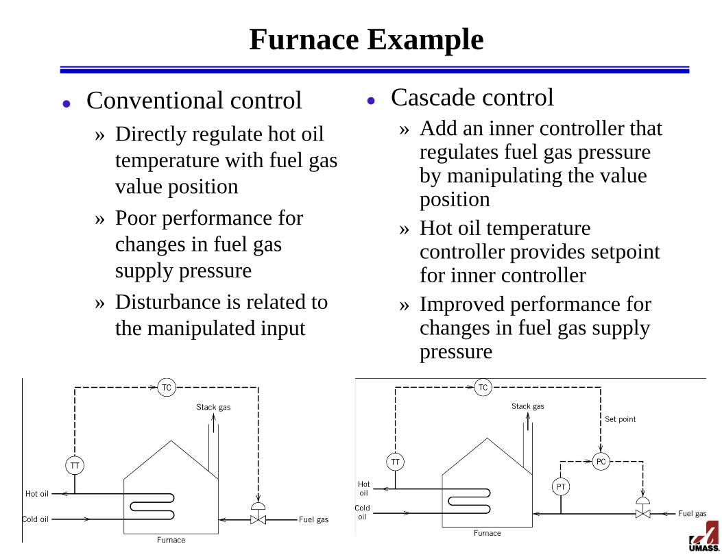
Furnace Example
Conventional control
» Directly regulate hot oil
temperature with fuel gas
value position
» Poor performance for
changes in fuel gas
supply pressure
» Disturbance is related to
the manipulated input
Cascade control
» Add an inner controller that regulates fuel gas pressure by manipulating the value position
» Hot oil temperature controller provides setpoint for inner controller
» Improved performance for changes in fuel gas supply pressure
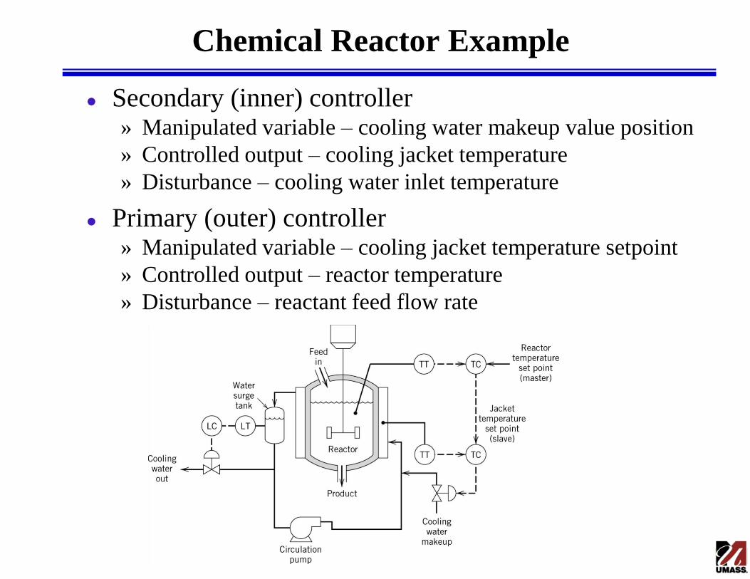
Chemical Reactor Example
Secondary (inner) controller » Manipulated variable – cooling water makeup value position
» Controlled output – cooling jacket temperature
» Disturbance – cooling water inlet temperature
Primary (outer) controller » Manipulated variable – cooling jacket temperature setpoint
» Controlled output – reactor temperature
» Disturbance – reactant feed flow rate
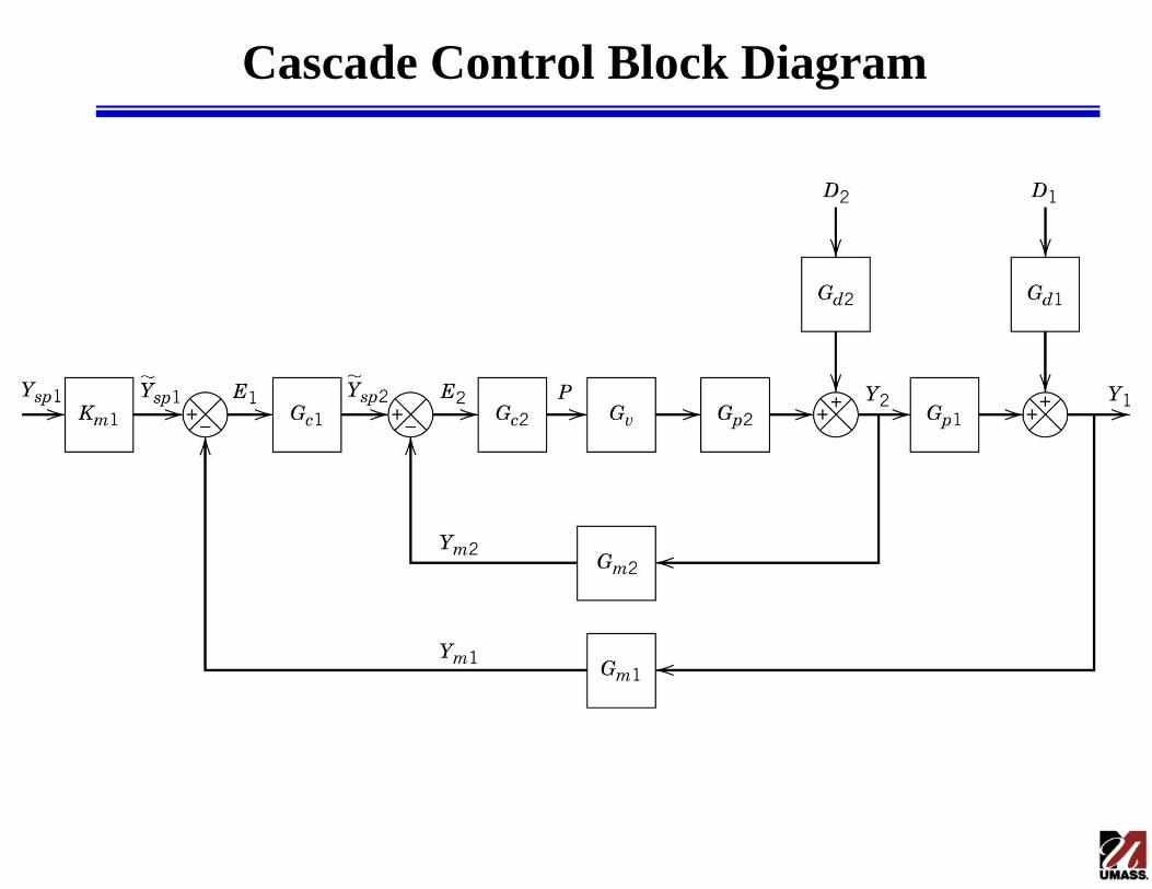
Cascade Control Block Diagram

Closed-Loop Transfer Function
General formula for closed-loop transfer functions
» Z = any variable in feedback system
» Zi = any input variable in feedback system
» Pf = product of all transfer functions between Z and Zi
» Pe = product of all transfer functions in feedback loop
Closed-loop transfer function for inner disturbance (D2)
e
f
iZ
Z
P
P
1
12211222
12
1111
12
2
1
2
222
2
2
21
222
22
2
2
11
11~
ppvccmpvcm
pd
pcm
p
pvcm
d
pvcm
pvc
sp
GGGGGGGGGG
GG
GGGG
GG
D
Y
GGGGG
G
D
YG
GGGG
GGG
Y
Y

Closed-Loop Stability
Characteristics equation for cascade control
Characteristic equation for conventional
control (Gm2 = 0, Gc2 = 1)
If inner loop has faster dynamics then the
outer loop, then cascade control usually has
improved stability characteristics
01 12211222 ppvccmpvcm GGGGGGGGGG
01 1211 ppvcm GGGGG
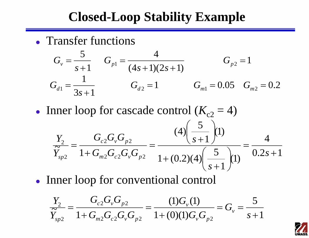
Closed-Loop Stability Example
Transfer functions
Inner loop for cascade control (Kc2 = 4)
Inner loop for conventional control
2.005.0113
1
1)12)(14(
4
1
5
2121
21
mmdd
ppv
GGGs
G
Gss
Gs
G
12.0
4
)1(1
5)4)(2.0(1
)1(1
5)4(
1~
222
22
2
2
s
s
s
GGGG
GGG
Y
Y
pvcm
pvc
sp
1
5
)1)(0(1
)1()1(
1~
2222
22
2
2
sG
GG
G
GGGG
GGG
Y
Yv
pv
v
pvcm
pvc
sp

Closed-Loop Stability Example cont.
Characteristic equation for cascade control
Characteristic equation for conventional control
Can use larger gains in outer control loop with cascade control than with conventional control
3.43
04531468
01
,1
1
23
12211222
uc
c
ppvccmpvcm
K
Ksss
GGGGGGGGGG
3.11
017148
01
,1
1
23
1211
uc
c
ppvcm
K
Ksss
GGGGG

Cascade Controller Design
Inner loop
» Typically a P or PI controller
» Tuned first with outer controller in manual
» Tuned to provide fast response to setpoint changes
Outer loop
» Typically a PI or PID controller
» Tuned second with inner controller in automatic
» Tuned to provide acceptable responses to setpoint changes and/or disturbances
» Must be retuned if inner loop is retuned

Direct Synthesis Design
Inner loop
Outer loop
2
2
processInner
2
22
22
2
2
22
222
22
2
2
1
11 If
1
1
1~
d
d
vp
cm
dm
d
vp
cd
pvcm
pvc
sp
G
G
GGGG
GG
G
GGGG
GGGG
GGG
Y
Y
1
1
processOuter
211
111
111
1
21
1
1
1211
1211
1111
1111
1
1
1
1 If
1
11
d
d
dpm
cmm
dmm
d
dp
c
d
pdcm
pdcm
pcm
pcm
sp
G
G
GGKGKG
GGK
G
GGG
GGGGG
GGGK
GGGG
GGGK
Y
Y

Cascade Controller Design Example
Transfer functions
Inner controller design
Outer controller design
1111
1110
4
1
5
2121
21
mmdd
ppv
GGGG
Gs
Gs
G
s
sK
s
s
s
s
G
G
GGG
sG
I
Ic
d
d
vp
cd
11
2.0
1
5
1
1
1
12.0
1
2
2
2
22
s
sK
s
s
s
s
G
G
GGKG
sG
I
Ic
d
d
dpm
cd
1
10
110
2
1
5
1
4
110
1
1
15
1
1
1
211
11

Conventional Controller Design
Process transfer function
IMC tuning (c = 5)
Simulink PID controller parameters
)110)(1(
20)()()()()( 121
sssGsGsGsGsG mppv
91.01111.01
21
2121
21
DI
c
cK
K
10.001.011.0 Dc
I
cc KD
KIKP

Simulink Implementation
Valve
5
s+1 To Workspace 1
output
To Workspace
setpoint
Setpoint
Process
4
10s+1Outer Controller
PID
Inner Controller
PID
Disturbance 2Disturbance
Add3 Add2Add 1
Add
0 5 10 15 20 25 30 35 40 45 50-0.2
0
0.2
0.4
0.6
0.8
1
1.2
Time
Outp
ut
Inner Disturbance
Cascade
Conventional
Setpoint

Closed-Loop Performance
0 5 10 15 20 25 30 35 40 45 50-0.2
0
0.2
0.4
0.6
0.8
1
1.2
Outp
ut
Time
Outer Disturbance
Cascade
Conventional
Setpoint
0 5 10 15 20 25 30 35 40 45 500
0.2
0.4
0.6
0.8
1
1.2
1.4Setpoint
Outp
ut
Time
Cascade
Conventional
Setpoint