Embed Size (px)
Citation preview

1 Induction & Fuel MeteringAviation Maintenance Technology253 - 254
2 INDUCTION• Induction = those locations of the engine nacelles where air entering
cannot avoid entering the cylinders.• There are two basic types• 1. non-supercharged• 2. supercharged
3 INDUCTION• Non-supercharged components• 1. Air scoop, • 2. Air filter, • 3. Ducting, • 4. Hot air selector box, heat muff, and ducting• 5. Fuel metering device,
4 INDUCTION• 6. Sensors• 7. De-icing devices• 8. Ducting to intake manifold, air reservoir is made by long convergent
duct.• Supercharged systems usually contain one of more of the above items,
and they will also contain some form of high volume air pump.
5 INDUCTION• Air Scoop• Usually a converging duct that will make use of the ram air effect of the
aircraft’s motion.
6 INDUCTION
7 INDUCTION• At scoop inlet, ram effect can increase the air pressure at the fuel
metering inlet in a super charging effect because air demand from throttle is less then ram air going in.
• This requires a diverging duct and an air reservoir.

8 INDUCTION• The velocity then decreases and pressure increases as the divergent duct
forms into a reservoir. • They may make scoops square and install guide vanes to reduce coriolis
swirling.
9 INDUCTION
10 INDUCTION• Air filters.• Wetted type mesh, 25 hrs; • Pleated paper element, up to 500 hrs; • Impregnated foam,
11 INDUCTION• polyurethane foam, • fuel resistant tacky stuff, • Made by Brackett w/STC, • good for 100 hrs, • do not clean foam element, • replace only, • has no problem w/water
12 INDUCTION• Decrease all replacement intervals if dusty and dirty.• Most common contaminant is dirt,• Is organic materials mixed with silica. • The organics create sludge, and the silica grinds up metal parts.
13 INDUCTION• Ducting • Preformed rigid aluminum or stainless .020"• Semi-rigid flexible, scat tubing = red -80° to 450°f • Cat tubing = black -65° to 300°f, commonly between air filter box and
carb.
14 INDUCTION• These are metal wire reinforced silicon paper,

• Can thread one piece into another.• Most common size is -8 = 2", • Size increments are 1/4”
15 INDUCTION• Hot air valve, muff and ducting• Alternate air =• Heat source provides alternate air source which melts carb ice. • Carb heat control is in for cool, out for heat.
16 INDUCTION• Lindbergh’s mechanic invented the first hot air device on the Spirit of St.
Louis.• Heat selector box has cold filtered inlet, hot unfiltered inlet, outlet, and flap
valve• Flap is on a shaft w/ pivot bushings, chafe occurs on shaft.
17 INDUCTION• If steel type find old seat assemblies from carb to replace bushings.• Heat muff is a shroud around muffler to be used as a hot air source. • Also may use inter-cylinder baffles, turbine side of turbo, oil sump, as
alternate hot air sources.
18 INDUCTION• Fuel metering devices• 1. pressure carburetors - TBI• 2. float carburetors• 3. continuous fuel injection• 4. pulsed fuel injection
19 INDUCTION• Sensors• MAP gauges are plumbed into the supercharger blower chamber, reading
the amount of boost.• Normally aspirated engine is plumbed somewhere between carb and
engine.
20 INDUCTION
21 INDUCTION

• Latent heat of vaporization is the energy required to convert a liquid to a gas, without changing the temperature.
• Laws of evaporation.• 1. The rate increases as temperature increases.
22 INDUCTION• 2. The rate increases as surface area exposed increases.• 3. The rate increases when atmospheric pressure decreases.• 4. The rate varies with the nature of the liquid.
23 INDUCTION• 5. The rate increases for water when the humidity decreases.• 6. The rate varies with the rate of air contact across the surface.• 7. Evaporation causes a cooling effect or loss of heat.
24 INDUCTION• Deicing systems• Three types of ice.• 1. Vaporization ice• 2. Throttle ice• 3. Impact ice
25 INDUCTION• Vaporization ice is fuel related. • Fuel gives up heat as it evaporates, cooling the air mass causing freezing
moisture.• Occurs from fuel discharge area onwards in the airstream.• More of a problem with float carbs
26 INDUCTION• Throttle ice occurs on the back side in the low pressure stall area of
throttle plate, • This ice commonly occurs from long slow descent.• In a pressure carb fuel nozzles are after Venturi thereby reducing
vaporization and throttle icing.
27 INDUCTION• Impact ice occurs when visible moisture at edge of freezing or colder, that
impacts and freezes or impacts and collects• Air frame subfreezing, temp 35°f or lower, droplets impact, explode and

freeze.
28 INDUCTION
29 INDUCTION• Can install carb temp probe into intake manifold with a green, yellow, red
gauge scale. • CAT = Carburetor Air Temperature• Constant speed = drop in MAP, fixed pitch = drop in RPM.
30 INDUCTION• Heating is done by routing warm air from a shroud around the exhaust
system into the intake to melt the ice.• The less dense hot air will initially give a loss in power, but if power then
climbs, you are melting the ice.• Some systems used alcohol in a reservoir to melt the ice. This will also
add fuel to the engine inlet.
31 INDUCTION• Intake system ducting• 1. intake manifold, oil bath & non oil bath• 2. cylinder distribution assembly• 3. intake runner tubes • 4. connection hoses
32 INDUCTION• 5. Cylinder attachment flanges and hardware.• 6. Support bracketing
33 INDUCTION
34 INDUCTION• It is common to see intake interiors slightly rough, from casting process.• Although this causes slight boundary layer turbulence it reduces fuel
condensation traveling into engine in droplet form.
35 INDUCTION• Polished intake interiors work well for high end racing performance but
provide terrible, stumbling low end performance.

36 INDUCTION• Porting and blue printing is the process of enlarging intake interiors, and
hand grinding all joints to remove any interior ridges at the joint. • Porting and polishing should not be done on aircraft engines unless
approved by the manufacturer.
37 INDUCTION• MAP Manifold Absolute Pressure• This is the pressure found between the air throttle valve, and the engine
intake valves.• Absolute means zero on the scale = complete vacuum, • ambient = approx. 29.92 ”Hg
38 INDUCTION• Any engine is primarily an air pump. • It draws air through the intake systems, and expels it, mixed with exhaust
gasses, out the exhaust systems.
39 INDUCTION• The air throttle valve is the major RPM or Power controlling device for any
spark ignited reciprocating engine. (Turbines and some Diesels are controlled by fuel metering only).
• It acts as a variable restriction to the air flow being drawn into the engine.
40 INDUCTION• Therefore when it is fully open the engine will attempt to maximize power
and RPM.• RPM may be limited by load or by maximum, open throttle air/fuel input.• MAP will be very close to ambient pressure in a nonsupercharged engine,
and may exceed ambient in a supercharged version.
41 INDUCTION• When the throttle is closed there will still be a slight amount of air passing
by it.• RPM and Power will be minimized to the lowest level possible while
continuing to run reasonably smooth. (If the “flyweight” momentum gets too low the power pulses tend to lope and stumble causing low idle misfires).
42 INDUCTION

• MAP will be very low, anywhere from 14 ”Hg - 22 ”Hg depending on engine type, health and current ambient conditions.
• As the engine warms up it becomes more efficient, so look for this during warm-up cycles.
43 INDUCTION• MAP and engine power have a direct correlation to BMEP in the
cylinders.• The maximum BMEP allowed in any given cylinder is set by the anti-
detonation factor of the fuel being used.• Lower octane fuels will be more likely to detonate in high BMEP engines.
44 INDUCTION• ALWAYS USE THE APPROPRIATELY RATED FUEL.• Note: Ignition timing can also effect BMEP, advanced timing will raise
BMEP to a point.
45 INDUCTION• Common problems, failures and diagnostic techniques• Leaks - small• Typically will go unnoticed.• May not get a slight rise in RPM during fuel cut-off.
46 INDUCTION• May get a slightly rough idle; this can be very hard to notice due to prop
thrusting.• Can cause mixture control to be shifted out of normal range.• Detection by visual inspection, or 1 psi air source, and soapy solution.• Smoke generators are now becoming available.
47 INDUCTION• Leaks - large• Engine won’t start, or runs very poorly.• Runs only in full rich position.• Severe back firing or after firing.
48 INDUCTION• Can be caused by closed throttle starting back fire.• MAP will indicate leaks as higher than normal, or lower if in boosted

range.
49 INDUCTION• High power flat - deep hum sometimes - OK at idle and low power• Restricted air filter, or induction blockage (pressure and floatcarbs will
react differently depending on the restriction)
50 INDUCTION• Restricted exhaust (very high EGTs)• Restricted fuel flow - (no hum with this, just power drop, high EGTs)• MAP will indicate the last two as higher than normal, and the first as lower
than normal.
51 INDUCTION• Supercharging• Its purpose is to increase the mass of the air/fuel charge going into the
engine for each revolution.
52 INDUCTION• Most supercharged engines also have constant speed propellers • They are designed to keep full power, manifold pressure at or above sea
level pressure.• Early systems could not exceed ambient pressures.
53 INDUCTION• Critical altitude = that altitude where the boosted manifold pressure can
no longer exceed sea level pressure.• As system technology developed we eventually designed supercharged
engines that exceeded ambient pressure in the intake system.
54 INDUCTION• This can also be done at lower altitudes for maximum power during
critical flight operations, • Is sometimes used for limited duration’s.• Maximum boost is determined by the strength of the intake system, or the
detonation characteristics of the engine
55 INDUCTION• General gas law = volume of a gas is inversely proportional to the
absolute pressure and is directly proportional to the temperature.

• (V1 * P1) / T1 = (V2 * P2) / T2
56 INDUCTION• Many things create high cyl pressure.• 1. Advanced ignition timing• 2. High density air• 3. Low octane, hot burning fuels• 4. Excessive compression (wrong engine parts)• 5. High intake temperatures
57 INDUCTION• High pressure creates high temperature.• At a certain temperature and pressure threshold, the pressure shock
wave, which travels faster then the heat/burn wave, starts to spontaneously ignite the air/fuel mixture in an uncontrolled fashion.
58 INDUCTION• This is called detonation, - FAA declares this to be a state of uncontrolled
burning.• Pre-ignition is when any source ignites the air/fuel charge prior to the
spark plug ignition.
59 INDUCTION• Air Density• Standard day conditions = 29.92 at sea level, at 15°c or 59°f, at 45°N lat.• Factors effecting density• Water and hi temps displace air molecules creating less density.
60 INDUCTION• Avogadro’s law states that any gas molecule will take up the same space
at the same temperature.• N2 has about twice the mass per molecule as H2O therefore the wet air
has less mass per unit of volume. (Lower density)
61 INDUCTION• Density altitude = common pilot nomenclature, higher numbers means
lower density.
62 INDUCTION• Supercharger is a non-positive displacement centrifugal air pump
(compressor) that increases the air density in the intake systems and the

cylinders.• Can be single or multi speed up to 13 to 1 ratio to crankshaft, in low
blower up to 42 inHg. • hi blower = up to 80 inHg
63 INDUCTION• When switching to high speed the manifold pressure will go up and oil
pressure will drop.• Supercharging is the overall term for pumping air into the engine
regardless of how this is accomplished.
64 INDUCTION• But is also the term for mechanically pumping air with a gear driven
compressor. (Some auto racing applications use a 4” wide belt drive)• Turbo supercharging uses exhaust to drive a turbine/compressor pump.
65 INDUCTION• In most super chargers fuel is mixed with air before supercharging
(internal), but not all (external).• This helps to vaporize the fuel.• Turbo superchargers have the air compressed prior to fuel metering
66 INDUCTION• If engine cannot boost above 30.00"Hg then it is a normalized boosted
engine.• It can be said the normalized engine regains normal ambient pressure, up
to the point where the turbo is at maximum output.
67 INDUCTION• Those that go above 30.00"Hg are known as supercharged. • Intercooler can be used on superchargers to cool the air charge after the
compressor
68 INDUCTION• With some engines there is a distribution impeller, but this nota charging
impeller. (more later)• On the R-985 it has an actual supercharger impeller at a 7.5 to 1 ratio to
the crankshaft.
69 INDUCTION

• It is possible to have superchargers that have several stages of charging much like a turbine engine, and, or they can have several speeds of compressor RPM.
• Stages and speeds. Can have • Stages: 1 2 2• Speeds: 2 2 1
70 INDUCTION• More then one compressor impeller creates the multiple stages• Only the gear driven Supercharger can have different speeds (Automatic
Gear box).
71 INDUCTION
72 INDUCTION• Dual speeds are controlled by solenoid switch.• Engine must have low compression ratios to prevent blow ups with high
pressures.• Supercharger clutches are engaged with oil pressure.
73 INDUCTION• Supercharging casing can be airfoil, vaned, venturies• Supercharger efficiency is by speed of rotation, and size of impeller
74 INDUCTION• Advantages• 1. More hp, • 2. shorter takeoff, • 3. bigger payload, • 4. Greater fuel efficiency, • 5. higher altitude
75 INDUCTION• Disadvantages, • 1. premature engine wear, • 2. more pre ignition and detonation, • 3. closer monitoring and maintenance,
76 INDUCTION

• 4. must use higher fuel grades, • 5. Harder to work on higher costs, • 6. low altitude restrictions due too much boost.
77 INDUCTION• Need to beef up the engine to handle the turbocharger or supercharger.• Intercooler is heat exchanger that cools air before going into engine to
increase density.
78 INDUCTION• Two common current producers of turbo-superchargers are Ray-Jay and
Garrett AirResearch.
79 INDUCTION• RayJay were the original type of turbo, with electric on/off solenoid, then
came the automatic controls. –VAPC, APC, Density controller,
• Distribution impeller = a mixing impeller, connected directly to the crankshaft that does not provide any boosting capacity.
80 INDUCTION• Never install a supercharger onto an engine that was not designed from
the ground up to be supercharged.• Conversions always loose reliability and longevity, and increase the
possibility of sudden catastrophic engine departation.
81 INDUCTION• Supercharger and *Turbosupercharger components.• 1. Compressor housing• 2. *Turbine housing• 3. Compressor impeller• 4. *Turbine impeller• 5. Drive shaft
82 INDUCTION• 6. Transmission assembly (Geared superchargers only)• 7. Diffuser• 8. Bearing sections• 9. Lubrication plumbing

• 10. Air ducting• 11. *Exhaust ducting• 12. Control systems
83 INDUCTION• Compressor housing is made of cast aluminum, cast, then machined.• Compressor impeller, centrifugal, is the upper deck pressure side, directs
air from the center to the outside. • Turbine housing, cast iron or steel,
84 INDUCTION• Turbines are impulse or reaction types, can be lost wax investment
casted then machined or ground to final shape. • Investment casting will lessen the porosity of the casting.
85 INDUCTION• Turbine temperatures are normally 1,700°f• Turbo superchargers can operate at speeds up to 100,000 RPM.
86 INDUCTION• Drive shaft connects the compressor impeller to the transmission
assembly or to the drive turbine impeller.• Transmissions are either simple geared drivelines or they can be multi-
speed transmissions that are hydraulically, or electro-hydraulically controlled.
87 INDUCTION• These latter units will include a clutch systems coupled to a sun/planetary
gear system, similar to an automatic automotive transmission.• Diffusers are two main types:• 1. Airfoil converging/diverging duct • 2. Straight vane
88 INDUCTION• The venturi-type diffuser is equipped with plain surfaces,• This type has been most widely used on medium powered, supercharged
engines • On large volume engines ranging from 450 hp upwards, either a vane or
airfoil type diffuser is widely used.

89 INDUCTION• Bearing housing, is usually either a floating type plain bearing with
pressurized oil (turbo superchargers) or they may use a double set of ball bearings with an oil bath spray.
• Shaft RPM can be as high as 40,000 to 50,000 RPM on some turbo superchargers.
90 INDUCTION• Lubrication plumbing includes standard AN hardware, hoses, and tubing,
designed to handle petroleum products at or below 100 psi.• The impeller shaft and gear are usually forged integrally of very high
grade steel.
91 INDUCTION• Air ducting can be anything from high pressure scat tubing to cast
aluminum runners and distribution manifolds. • This all needs to be considerably stronger than normally aspirated
induction assemblies. Do not interchange these parts.
92 INDUCTION• Exhaust ducting is usually made from the same materials (Stainless
Steel) as the rest of the exhaust system.• Since the system has so much motion from vibration and heat expansion
there will probably be flex, or expansion joints installed.
93 INDUCTION• This may be encased in heat shielding of some form, particularly when
installed on aircraft with streamlined cowlings.• DO NOT leave this shielding off the aircraft for any flight operations.
94 INDUCTION• Control systems• Some early systems were manually controlled via a push/pull vernier near
the throttle control.
95 INDUCTION• During specific altitude and power conditions the pilot would engage the
supercharger clutches via oil pressure controls, or start closing the turbosupercharger wastegate.

96 INDUCTION• Wastegate is a device used on turbo superchargers that allows exhaust
gasses to bypass the drive turbine.• Typically a closed wastegate means full turbine output, (the bypass is
closed).• Deck pressure is that pressure just after the compressor.
97 INDUCTION• Throttle valve is between compressor and intake system.• Fuel is injected into intake close to intake valves.
98 INDUCTION• Several systems are described in the following slides.• There are numerous configurations.• They all function by use of pressure control or density control, or both.
99 INDUCTION• A density regulator will measure for pressure and temperature.• A pressure regulator will only regulate for pressure.• The most simple system is a outside adjustable bypass screw.
100 INDUCTION• Other smaller systems may rely on only density regulation.• As temperature or pressure changes the oil pressure is allowed to build or
release on the wastegate controller.• These usually default to open with no pressure.
101 INDUCTION• These controllers are on the return side of the actuator.• Pressure controllers can measure pressure, density or be differential,
comparing two differing pressures.
102 INDUCTION• One Lycoming system has four main components• 1. Turbo supercharger• 2. Density controller• 3. Differential controller• 4. Bypass assembly (wastegate)
103 INDUCTION

• Turbo supercharger is a sea level boosted engine with a critical altitude of 19,000 ft.
• Density controller controls oil pressure of wastegate actuator only during full power operation.– It is density sensing, temp. and press.
104 INDUCTION–Bellows opens oil valve when deck pressure is close to ambient,
otherwise it stays closed.• Differential controller controls oil pressure of wastegate actuator by
means of a differential diaphragm with deck pressure on one side and post throttle MAP on the other side.
105 INDUCTION• The differential controller will try to maintain a pressure drop across the
throttle valve of 2 - 4 “Hg.• When it opens the waste gate opens.• This valve will remain closed during wide open throttle operation since
there is not enough differential to open it.
106 INDUCTION• Another system uses a variable-pressure controller instead of a density
and differential controllers.• This device works similar to the differential controller but it also has a cam
and plunger that is actuated by throttle linkage.
107 INDUCTION• Over high deck pressure pushes the poppet down and open on the top
end, and the cam pushes the poppet follower up and open from thebottom end during lower power settings.
• A vacuum filled bellows and several balancing springs work to keep the poppet valve closed.
108 INDUCTION• Continential had earlier units which used three controllers and later units
combined these into one unit with cam/throttle linkages.• These are:
–absolute pressure controller– rate of change controller

–pressure-ratio controller
109 INDUCTION– In similar fashion as they bleed off waste gate control oil opening the
waste gate.–They are hooked up in parallel so that each may independently dump
exhaust gas.
110 INDUCTION–Absolute pressure controller is a maximum upper deck pressure limiter.–Rate of change controller bypasses wastegate oil if the deck pressure
changes faster then 6.5 in Hg/S
111 INDUCTION–The engine can over boost momentarily during rapid throttle
application.–This may only oscillate the power, or it may cause detonation for a
short period.
112 INDUCTION–Pressure ratio controller will maintain a pressure ratio between the deck
pressure and inlet ram air of 2.2:1 at any altitude above 16,000 ft.–This prevents excessive heat buildup in the deck airstream which can
cause detonation.
113 INDUCTION• The variable absolute pressure controller combines these three units and
it functions in a manner identical to the Lycoming variable controller.–This system also incorporates a overpressure MAP relief valve.
114 INDUCTION– It uses varible fuel pressure as the operating force.
• Another turbo supercharger control system uses an adjustable orifice that also includes an overpressure relief valve
115 INDUCTION• Adjustment criteria, at component replacement, or engine overhaul
–Test run on ground, –Calibrate MAP gauge, –Slowly advance throttle watching MAP

116 INDUCTION– Install thermocouple to know temperature at specified port in
compressor, then use chart to check temp against pressure read.–Slow smooth throttle movement.
117 INDUCTION–Frequent oil changes for any turbo supercharged engines.–Plan on higher service requirements inspection wise as well.–One quote is $1.50 per hour flight time in additional costs.
118 INDUCTION• Bootstrapping is when as you increase power, turbo increases more, then
you are over powered in a cyclic manner.• It is an undesirable cycle of turbocharging events causing the manifold
pressure to drift in an attempt to reach a state of equilibrium.
119 INDUCTION• Bootstrapping occurs when the waste gate is closed or mostly closed.• Rapid movement of the throttle can cause a certain amount of manifold
pressure drift in a turbocharged engine. • Bootstrapping is when the drift persists.
120 INDUCTION• Intercoolers may exist on any of these devices.• They provide pressurized intake air cooling.• Sonic venturis are used to increase cabin air volume input, sacrificing
limited amounts of air pressure.
121 INDUCTION• Over boost is when the MAP upper pressure limit has been exceeded.• This will break parts, cause detonation and break more parts.
122 INDUCTION• Turbo compounding• The turbocompound engine consists of a conventional, reciprocating
engine in which exhaust driven turbines are coupled to the engine crankshaft.
123 INDUCTION
• This system of obtaining additional power is sometimes called a PRT (power recovery turbine) system.
• Power recovery turbine systems, because of weight and cost considerations, are used exclusively on very large reciprocating engines.
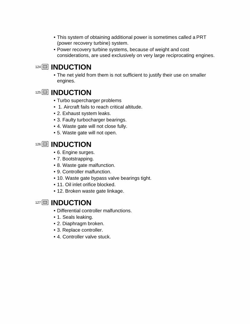
124 INDUCTION• The net yield from them is not sufficient to justify their use on smaller
engines.
125 INDUCTION• Turbo supercharger problems• 1. Aircraft fails to reach critical altitude. • 2. Exhaust system leaks. • 3. Faulty turbocharger bearings.• 4. Waste gate will not close fully.• 5. Waste gate will not open.
126 INDUCTION• 6. Engine surges.• 7. Bootstrapping. • 8. Waste gate malfunction. • 9. Controller malfunction. • 10. Waste gate bypass valve bearings tight.• 11. Oil inlet orifice blocked.• 12. Broken waste gate linkage.
127 INDUCTION• Differential controller malfunctions.• 1. Seals leaking. • 2. Diaphragm broken.• 3. Replace controller.• 4. Controller valve stuck.

1 Aircraft Fuel Metering
2 Purpose of metering• To adequately mix the proper amount of fuel with the combustion air
entering into an engine, during all phases of engine operation.
3 Section Outline• Terms• Fuel metering concepts
–Characteristics of fuels–Characteristics of air–Engine operational needs–Basic system outline
4 Section Outline• Carburetion Principles
–Air metering–Fuel metering–Enrichment / derichment–Acceleration systems
5 Section Outline• Float Carburetors• Pressure Carburetors• Fuel Injection Systems• Diagnostic and troubleshooting
–Basic strategy development–Common failure areas
6 Terms• Take-off power = maximum power allowed for take-off operations.
–usually limited to 1 - 5 minutes• Rated Power = highest power Mfg.. will guaranty the engine to produce
continuously at a given altitude.
7 Terms• Absolute altitude = highest altitude which the engine will run.

• Friction horsepower = the horsepower required to overcome friction and accessories.
8 Terms• Mechanical efficiency = BHP/IHP• Brake horse power = the power available to perform work.• Indicated horse power = P.L.A.N.K / 33,000 ft.lbs/min
9 Terms• P = mean effective pressure• L = length of stroke in Ft.• A = area of bore in sq/in• N = # of power strokes per min (rpm/2)• K = # of cylinders
10 Terms• MEP = mean effective pressure
11 Terms• Otto cycle = the four stroke cycle
– Intake–Compression
– ignition (event only)–Power–Exhaust
12 Terms• Otto
pressure cycle
13 Terms• Density altitude = the effective altitude of prevailing conditions presented
in terms of standard conditions.• Carburetor = a device that meters air and fuel into the intake system.• Metering = to provide in measured quantities (Websters)
14 Terms

• Fuel injection = similar to carburetion but fuel distribution occurs at a different location from air metering, usually just behind the intake valve.
15 Terms• Octane rating
–determined by the percentage of iso-octane that must be mixed with normal heptanes to reduce detonation.
–more iso-octanes reduce detonation to a point.
16 Terms• Air metering force
–Those forces created by air being drawn into the engine because of pressure differential.
• Fuel metering force–Air metering forces that are used to determine the air mass entering the
engine for fuel metering.
17 Terms• Fuel distribution forces
–Those forces used to distribute and atomize the fuel into the intake air stream.
• Fuel metering and distribution forces may or may not be the same force.
18 Terms• Full rich:
–mixture control setting that provides the maximum fuel flow for any given throttle setting.
• Engine will run cooler but will consume fuel at the greatest rates.
19 Terms• Rich best power:
– the richest mixture control setting that does not reduce RPM or power.–May not be used during takeoff, or may be used for a limited duration
above certain power settings.
20 Terms• Lean best power:
–The leanest mixture control setting that does not cause a lower RPM.

–This is higher than best economy.–Engine temp goes up as it gets leaner.–Not used for high power settings.
21 Terms• Best economy mixture:
–The leanest mixture control setting that will not damage the engine.–This setting is close to a Stoichiometric ratio. One where all fuel and
oxygen will be consumed.–Produces more heat than the others.
22 Terms• Best power mixture:
–The mixture control setting that produces the best overall power without damaging the engine.
–Will be different for different throttle settings.–Between best rich and best lean.
23 Terms• Flame propagation is slower when rich or lean from lean best power.• Temperature is higher when lean, to a point - misfiring• EGT gauge is very useful for setting mixture.
24 Terms
25 Fuel metering conceptsfuel characteristics
• Aviation gasoline = hydrocarbon fuel– C5H12 - C8H18 = common fuel range– 2 C5H12 + 16 O2 => 10 CO2 + 12 H2O– 2 C5H12 + 16 O2 => 6 CO2 + 12 H2O + 2 NOx + 4 CO = incomplete
burn– NOx = the brown stuff of smog– CO = the most toxic part of smog
26 Fuel metering conceptsfuel characteristics
• Aviation gasoline has a high rate of vaporization.

• Volatile = readily vaporizeable at a relatively low temperature.• Has come in a number of different grades.• Most common grade available = 100LL
27 Fuel metering conceptsfuel characteristics
• Avgas is made up of many differing molecules of similar structure.• All gasoline's are composed of many grades of fuel oils.• This causes them to have boiling points that vary within a range.• Typical boiling point will range from 100°f - 250°f
28 Fuel metering conceptsfuel characteristics
• Octane rating is a rating of resistance to detonation. Higher is better.• Octane calculated by three methods
–RON = Research Octane Number–MON = Motor Octane Number– (RON+MON)/2 = average of both–Latter is the most common rating.
29 Fuel metering conceptsfuel characteristics
• Octane rating may be achieved by mixing high octane iso-octanes with lower octane heptanes.
• The iso-octanes reduce detonation• The heptanes provide more Btu's• Today many different blends and additives are used in gasoline's.
30 Fuel metering conceptsfuel characteristics
• Dual octane ratings indicate the lean octane value and the rich octane value.
• 100 octane would have the anti-knock qualities of 100% iso-octane.• TEL is used to achieve higher than 100% iso-octane ratings.
31 Fuel metering conceptsfuel characteristics
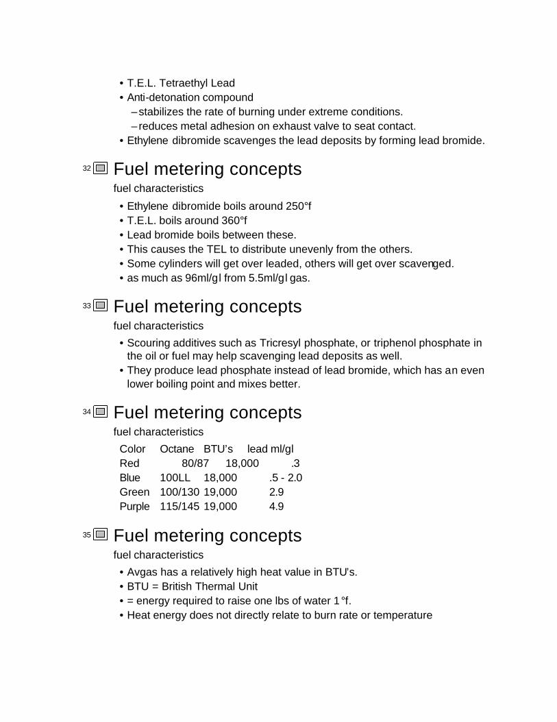
• T.E.L. Tetraethyl Lead• Anti-detonation compound
–stabilizes the rate of burning under extreme conditions.– reduces metal adhesion on exhaust valve to seat contact.
• Ethylene dibromide scavenges the lead deposits by forming lead bromide.
32 Fuel metering conceptsfuel characteristics
• Ethylene dibromide boils around 250°f• T.E.L. boils around 360°f• Lead bromide boils between these.• This causes the TEL to distribute unevenly from the others.• Some cylinders will get over leaded, others will get over scavenged.• as much as 96ml/gl from 5.5ml/gl gas.
33 Fuel metering conceptsfuel characteristics
• Scouring additives such as Tricresyl phosphate, or triphenol phosphate in the oil or fuel may help scavenging lead deposits as well.
• They produce lead phosphate instead of lead bromide, which has an even lower boiling point and mixes better.
34 Fuel metering conceptsfuel characteristics
Color Octane BTU’s lead ml/glRed 80/87 18,000 .3Blue 100LL 18,000 .5 - 2.0Green 100/130 19,000 2.9Purple 115/145 19,000 4.9
35 Fuel metering conceptsfuel characteristics
• Avgas has a relatively high heat value in BTU’s.• BTU = British Thermal Unit• = energy required to raise one lbs of water 1°f.• Heat energy does not directly relate to burn rate or temperature

generated.
36 Fuel metering conceptsfuel characteristics
• Ignition temperatures of fuels.–Natural gas 1,100°f–Gasoline's 600-800°f–Diesels 300-400°f–Jet fuels 300-450°f–Spark plug arc 500-1800°f–Best arc temp 900-1300°f
37 Fuel metering conceptsfuel characteristics
• Lower atmospheric pressures will increase rate of vaporization• will also lower boiling temperatures• Fuel must be vaporized to oxidize or burn.• Fuel must be liquid to be pumped.
38 Fuel metering conceptsfuel characteristics
• The primary purpose of a fuel distribution device is to administer fuel in an atomized state that is close to vapor.
• Heat energy must then complete the vaporizing process.• Excess fuel causes excess vaporizing which cools the combustion
process.
39 Fuel metering conceptsfuel characteristics
• Fuel can vaporize in warm engine compartment fuel lines.• Worse on hot soaked engine being restarted. • Any turbulence generators in fuel delivery system can accelerate “vapor
lock” conditions
40 Fuel metering conceptsfuel characteristics
• Vapor lock areas

–sharp bends–high rise areas– routing close to hot components–pump inlets–carburetor inlets
41 Fuel metering conceptsfuel characteristics
• Booster pumps will reduce possibility of vapor lock.• Gravity feed systems not likely to vapor lock.• Higher volatility fuels more likely to vapor lock.
42 Fuel metering conceptsfuel characteristics
• Typical method to “repair” vapor lock –Mixture full rich–Throttle cracked - slightly open–Magnetos on–Start engine– If it quickly dies then it was probably vapor locked
43 Fuel metering conceptsfuel characteristics
• Bleed the systems with aux pump.–Mixture full lean or at idle cutoff - prevents flooding–Throttle full open – boost pump on–Electric pump on–Wait twenty seconds to purge vapor.–Start normally.
44 Fuel metering conceptsfuel characteristics
• Automotive fuels–Several STCs exist for the use of auto gas.–May only require an identifier hose clamp on a push rod tube.–Generally only good for low compression engines.

45 Fuel metering conceptsfuel characteristics
–won’t have a loss of power but may have reduced high power duration.–Auto fuel has many additives that are unknown or proven incompatible
with aviation systems.–Some auto gas blends have higher a volatility then avgas and are more
likely to vapor lock.
46 Fuel metering conceptsfuel characteristics
• Methyl tertiary butyl ether–can attack rubber causing swelling–can make humans sick
• Methyl Alcohol–can attack rubber causing swelling–can make humans sick–can rust components
47 Fuel metering conceptsfuel characteristics
48 Fuel metering conceptsair characteristics
• Air is a compound of several gasses–76% nitrogen–21% oxygen–2.1% carbon dioxide and rising
– the rest is the remaining heavier gasses.– lighter gasses tend to rise away.
49 Fuel metering conceptsair characteristics
• All of these gasses are displaced by moisture.• Since moisture content varies from none to complete saturation it is not
considered to be a part of air.
50 Fuel metering concepts

air characteristics
• Fuel requires the oxygen for combustion which releases large amounts of heat.
• Elements other than the moisture and oxygen, resist involvement in the combustion process.
51 Fuel metering conceptsair characteristics
• Nitrogen = N–molecular weight of 14– forms in molecules of two or more–very resistant to molecular interaction with fuel or oxygen–will bond with hydrogen to form ammonia's
52 Fuel metering conceptsair characteristics
• Oxygen = O–molecular weight of 8– forms molecules of two commonly–easily interacts with many substances.– interaction will consume or release energy
53 Fuel metering conceptsair characteristics
• Water vapor = H2O–molecular weight of 10–will weakly bond with itself– releases high amounts of energy when forming.–displaces heavier N2 and O2 molecules.
54 Fuel metering conceptsair characteristics
• Avogadro’s law–molecules of any gas demand the same space for a given temperature.
• A water molecule will demand the same space as a nitrogen or oxygen molecule.
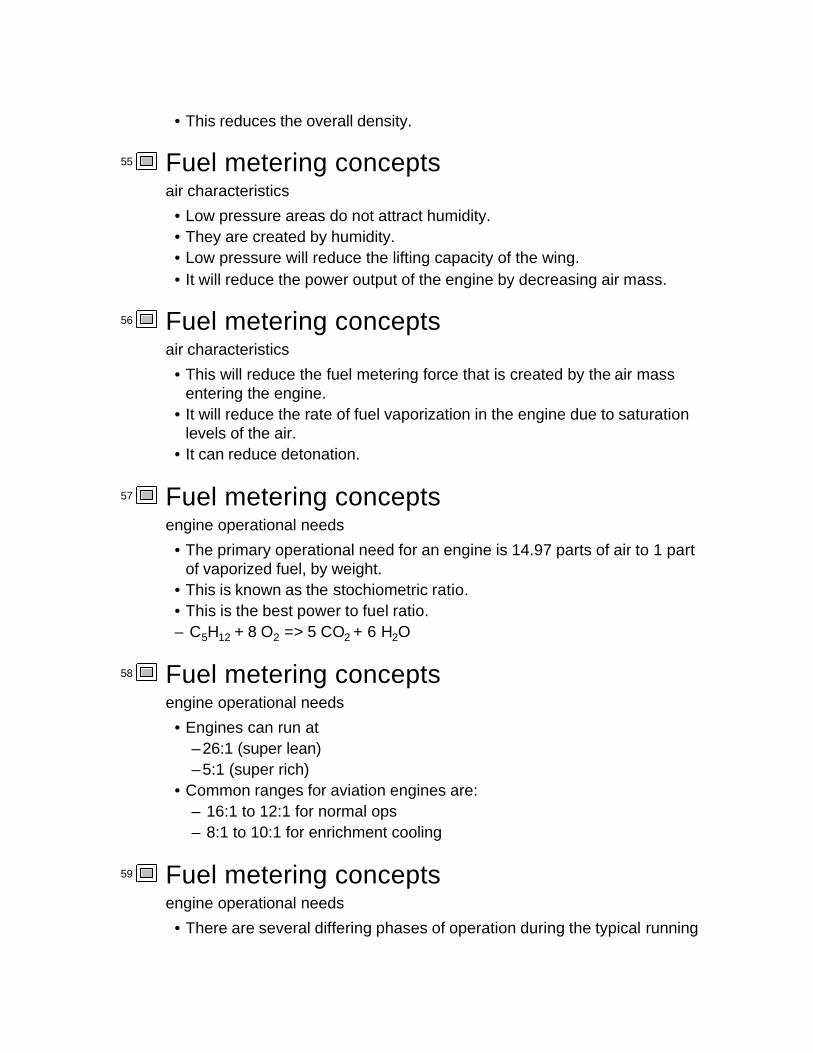
• This reduces the overall density.
55 Fuel metering conceptsair characteristics
• Low pressure areas do not attract humidity.• They are created by humidity.• Low pressure will reduce the lifting capacity of the wing.• It will reduce the power output of the engine by decreasing air mass.
56 Fuel metering conceptsair characteristics
• This will reduce the fuel metering force that is created by the air mass entering the engine.
• It will reduce the rate of fuel vaporization in the engine due to saturation levels of the air.
• It can reduce detonation.
57 Fuel metering conceptsengine operational needs
• The primary operational need for an engine is 14.97 parts of air to 1 part of vaporized fuel, by weight.
• This is known as the stochiometric ratio.• This is the best power to fuel ratio.– C5H12 + 8 O2 => 5 CO2 + 6 H2O
58 Fuel metering conceptsengine operational needs
• Engines can run at –26:1 (super lean)–5:1 (super rich)
• Common ranges for aviation engines are:– 16:1 to 12:1 for normal ops– 8:1 to 10:1 for enrichment cooling
59 Fuel metering conceptsengine operational needs
• There are several differing phases of operation during the typical running
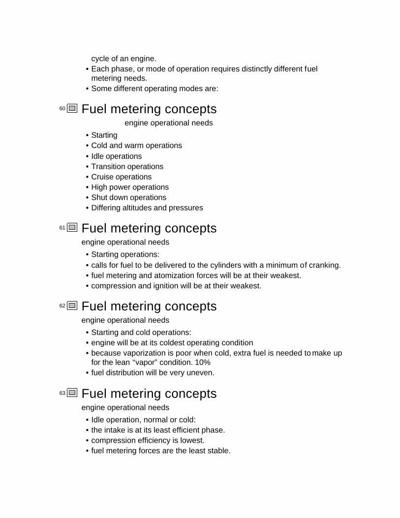
cycle of an engine.• Each phase, or mode of operation requires distinctly different fuel
metering needs.• Some different operating modes are:
60 Fuel metering conceptsengine operational needs
• Starting• Cold and warm operations• Idle operations• Transition operations• Cruise operations• High power operations• Shut down operations• Differing altitudes and pressures
61 Fuel metering conceptsengine operational needs
• Starting operations:• calls for fuel to be delivered to the cylinders with a minimum of cranking.• fuel metering and atomization forces will be at their weakest.• compression and ignition will be at their weakest.
62 Fuel metering conceptsengine operational needs
• Starting and cold operations:• engine will be at its coldest operating condition• because vaporization is poor when cold, extra fuel is needed to make up
for the lean “vapor” condition. 10%• fuel distribution will be very uneven.
63 Fuel metering conceptsengine operational needs
• Idle operation, normal or cold:• the intake is at its least efficient phase. • compression efficiency is lowest.• fuel metering forces are the least stable.

• fuel vaporization and distribution can be very poor.
64 Fuel metering conceptsengine operational needs
• Transitional operations:• engine will be trying to accelerate• may be operating partially on several fuel metering systems• air fuel ratios may need to cycle between lean and rich as throttle and
RPM are transitioned.
65 Fuel metering conceptsengine operational needs
• Cruise operations:• power demand is low to medium.• best fuel economy is desired.• highest portion of flight time.• vaporization is good.• cooling demands are low.• most likely to develop icing
66 Fuel metering conceptsengine operational needs
• High power settings:• for take off and climb.• may have duration limits.• most cooling needed.• best vaporization condition.• most likely detonation phase.• compression and ignition at their best.
67 Fuel metering conceptsengine operational needs
• Shut down operations:• post metering fuel system needs to be scavenged of burnable mixture.• combustion chamber needs to be vented of varnish developing gasses.• engine needs to be safely shut down and defused, pending magneto

switch failures and or hot spots.
68 Fuel metering conceptsengine operational needs
• Altitude - pressure compensation:• appropriate air:fuel ratios must be maintained at any altitude o r pressure.• can be manual, automatic or both.• air:fuel ratios may need manual compensation for unusual operations.
–such as starting, stopping, hot, cold, emergencies, vapor lock, etc.
69 Fuel metering conceptsengine operational needs
70 Fuel metering conceptsbasic system outline
• Fuel storage and delivery systems must store fuel until needed, then deliver fuel to the fuel metering system, as needed.
• Fuel storage is either in wings, fuselage, or both.
71 Fuel metering conceptsbasic system outline
• Fuel storage systems regulated by FAR 23, covered in AMT 100.• Common source of fuel contaminants• Materials compatibility is critical
–Rubber, sealants, seals, composites
72 Fuel metering conceptsbasic system outline
• Must have–Debris / moisture sumps w/ drains–Sealed Fuel caps w/labeling–Fuel quantity indicator–Fuel outlet screen–Pre-firewall off/on/selector valve w/ detents for each engine.
73 Fuel metering concepts
basic system outline
–valve can’t pass through “OFF”• Fuel outlet screen must be 8 - 15 mesh.• must have surface area 5 times the outlet cross-sectional area.• Gascolater mesh 25 - 1• Carb strainer mesh 40 - 1
74 Fuel metering conceptsbasic system outline
• Venting systems must be present and functional.• It must prevent negative pressure differential.• Cannot allow fuel to be siphoned.• Must vent overboard safely.
75 Fuel metering conceptsbasic system outline
• Delivery systems can be gravity feed or pump systems.• Gravity feed systems must provide 150% of maximum fuel demand.• Pump systems must provide 125% maximum fuel demand.
76 Fuel metering conceptsbasic system outline
• No fuel delivery system device can cause stoppage of fuel flow for any reason or during any failure mode.(all must contain bypass systems)
77 Fuel metering conceptsbasic system outline
• Mechanical engine powered pump is the most common delivery system.• Pump systems can be single or dual pump systems.
–Non-positive displacement centrifugal pumps are used for fuel sump pick-up when line head pressure is too low.
78 Fuel metering conceptsbasic system outline
–Positive displacement pumps are usually an engine driven primarypump.
–They can be geared, pulsed, stroked, vaned, wobble or gerotor.

–They may use a loop system with fuel return to pump inlet.
79 Fuel metering conceptsbasic system outline
• Tubing, hoses, fire sleeve, and filtration as per FAR 23, 33, and 34.• Fire sleeve forward of the firewall.• Main filtration at the lowest point.• Firewall sealed and fuel flow shut off required.• Alternate or hot air source required.
80 Fuel metering conceptsbasic system outline
• Air metering system –must be able to vary air volume entering the engine– is primary power/rpm control
• Fuel metering system –must have a means to determine approximate air mass entering into
combustion chamber.
81 Fuel metering conceptsbasic system outline
• Fuel distribution system –must have a means to atomize fuel evenly into the combustion air
stream. (complete fuel vaporization is the ideal situation)• Air / air-fuel compressor system.
–Pre or post fuel metering/distribution
82 Fuel metering conceptsbasic system outline
• Induction systems carries meter air and possibly metered fuel into cylinder heads.
• Combustion chamber intake valve– regulates air/fuel charge into combustion chamber– is the end of fuel metering/induction
83 Carburetion Principles• Air metering principles

• Fuel metering principles• Fuel distribution principles• Enrichment / derichment principles
84 Carburetion PrinciplesAir Metering
• Air metering is critical to spark ignited engines.–because gasoline will combust over a wide range of mixture ratios
regulating RPM/power with fuel control only would not be responsive.–deceleration won’t occur until the engine suddenly stops firing.
85 Carburetion PrinciplesAir Metering
• True rotary engine.–no air metering throttle.– fuel metering off / on only.– take off and cruise was at full power–descending and landing was at engine off, no power.
86 Carburetion PrinciplesAir Metering
• Air metering– the most common device used is a throttle butterfly valve.– it is a coin shaped disc that is bisected by a shaft.– the shaft rotates opening or closing the throttle bore.
87 Carburetion PrinciplesAir Metering
• Most reciprocating engines will consume six pounds of air per hour per brake horsepower
88 Carburetion PrinciplesAir Metering
Closed, engine off or at idle
89 Carburetion Principles
Air Metering
Mid-throttle, engine cruising
90 Carburetion PrinciplesAir Metering
Full-throttle, engine full power
91 Carburetion PrinciplesAir Metering
• Another less common air metering device is the slide throttle.–uses a cylindrical tube that slides in or out of the throttle bore, at right
angles to the bore.
92 Carburetion PrinciplesAir Metering
93 Carburetion PrinciplesAir Metering
94 Carburetion PrinciplesAir Metering
95 Carburetion PrinciplesAir Metering
96 Carburetion PrinciplesAir Metering
97 Carburetion PrinciplesAir Metering
• One final function of air metering is to determine which carburetor fuel metering mode or system should be used.
• Most carburetors will have more than one fuel metering pathway.• Commonly this is a direct function of throttle plate position.

98 Carburetion PrinciplesFuel Metering
• Fuel metering principles–measure the rate of air flow–provide a pre-metered staging area for fuel to control metering
pressure.–using predetermined values, meter the appropriate fuel to the
distribution devices.
99 Carburetion PrinciplesFuel Metering
• Bernoulli’s Principle–a fluid moving through a converging / diverging duct will increase
velocity and decrease pressure.–by comparing reduced pressure with ambient pressure one has an
accurate estimation of fluid volume passing the restriction.
100 Carburetion Principles Fuel Metering
101 Carburetion Principles Fuel Metering• This is known as the Venturi effect.
– the force created by this pressure differential can be used to directly meter and distribute fuel.
–or it can be used for metering purposes only, with fuel distribution accomplished elsewhere.
102 Carburetion Principles Fuel Metering• Fuel staging area is usually regulated by a poppet valve.
–provides a collection area where pre-metered fuel pressure is stabilized.
–can be controlled by floats or pressure diaphragms.
103 Carburetion Principles Fuel Metering• Fuel metering is usually accomplished with removable metering ports
(jets).– is similar to measuring the air flow.–controlling a pressure differential across a known restrictor allows

accurate metering of fuel flow.–venturi differential can be the only source for fuel metering forces
104 Carburetion Principles Fuel Metering• Fuel metering ports are removable so they may be replaced with different
sizes.• Drilling to adjust usually destroys them.• The metered fuel circuit may be vented with an air bleed jet to increase
metering force and aid in atomization.
105 Carburetion Principles Fuel Discharge• Centrally located in the airstream of the carburetor.• Primary purpose is to carry metered fuel to the center of the airstream
and discharge it.• Secondary purpose is to atomize fuel as much as possible.
106 Carburetion Principles Fuel Discharge• Fuel discharge nozzle can be a simple pipe jutting into the airstream.• Can include a secondary venturi to provide additional pressure differential
and stable airflow.• May have a concentric nozzle head with equally spaced fuel ports.
107 Carburetion Principles Fuel Discharge• Nozzle head may be shaped to increase venturi effect.• May include an air bleed mixing chamber in discharge head.• May be located on either side of throttle plate. (pressure vs. float)
108 Carburetion Principles enrichment / derichment• Fuel enrichment/derichment is caused by several common techniques.
–physically alter venturi pressure differential.– turn off or on a separate fuel path.– turn off or on a separate air path.–or any combination of the above.
109 Carburetion Principles enrichment / derichment• Two methods for altering venturi pressures.
–1. choke = another butterfly valve upstream of the throttle valve and the fuel metering venturi.

–closing causes greater fuel metering force, thereby enriching the mixture.
– rarely used in aviation.
110 Carburetion Principles enrichment / derichment–2. Alter fuel staging area pressure at the point where it is metered.– this can be done several ways depending on carburetor system.–pre-metered fuel may be at ambient pressure, above ambient. or below
ambient.
111 Carburetion Principles enrichment / derichment• Turning on or off enrichment air bleed or fuel circuits or pathways is done
by:– linkages to the throttle control.–placement or position of the throttle plate
112 Carburetion Principles enrichment / derichment• enrichment / derichment may be used for:
–hot or cold starting.–high altitude / low pressures.– full power cooling.– fuel conservation.
113 Carburetion PrinciplesAutomatic Mixture Controls
• These devices are used on all Stromberg Pressure carbs and many of their float carbs.
• Consists of an aneroid bellows filled with nitrogen and or light oil.• They are responsive to both temperature and pressure changes
114 Carburetion PrinciplesAutomatic Mixture Controls
• This means they are density controllers.• The internal oil in the webs of the bellows act as dampers for vibration• The plunger valve is cut with two different tapers.
115 Carburetion Principles
Automatic Mixture Controls
• This helps to correct for the non-linear changes in temperature and pressure in the atmosphere.
116 Carburetion Principles acceleration systems• Acceleration systems
–may be needed to add fuel for rapid crankshaft acceleration.–normal fuel metering forces cannot respond fast enough to meet the
extra demand.
117 Carburetion Principles acceleration systems• Most common system is a “one shot per throttle application” piston pump
system.–may or may not have a separate distribution path.–used more commonly on higher powered systems.
118 Carburetion Principles acceleration systems• Pressure Carburetors commonly use a diaphragm type pump.• Can be mechanically driven by throttle or:• Can use MAP to drive pump.
– low MAP draws diaphragm back filling chamber.–High MAP releases this into air.
119 Carburetion Principles
120 Carburetion Principles
121 Carburetion Principles
122 Carburetion Principles
123 Carburetion Principles
124 Carburetion Principles• This can be a one check valve or two check valve pump.
– the one valve type draws fluid into the pump chamber faster than low

pressure venturi air can be back drawn through the distribution nozzle
125 Carburetion Principles• The two check valve systems draw fuel in through one valve and push
fuel out through the other one.• These check valves are usually a ball type valve, that may or may not
incorporate a spring.• They fall out and disappear easily during repair or overhaul.
126 Carburetion Principles
127 Float Carburetors• Manufacturers
–Marvel-Schebler–Bendix/Stromberg–Bing
128 Float Carburetors• Model identification systems
–Marvel/Schebler• MA = updraft• HA = sidedraft
–Bigger secondary numbers mean larger engine application.–Use specific Marvel/Schebler P/N
129 Float Carburetors• Model identification systems
–Stromberg-Bendix–5 to 6 groups–First Group:
• NA - Natural Atomization• P - Pressure• Q - Small Pressure
130 Float Carburetors• Model identification systems
–Second Group:• Barrel types

–Third Group• Barrel Size from 1 3/16”, 1/4” increments
131 Float Carburetors• Model identification systems
–Fourth Group:• Model letter = major modification signifying model change.
–Fifth Group:• Model number = minor modification not enough for new model
change.
132 Float Carburetors• Model identification systems
–Sixth Group:• Sub-mod letter = very minor change.
133 Float Carburetors• Model identification systems
–Bing• Uses a number commonly• Describes the throttle bore in millimeters.• Usually cable slide throttle type.• Can be vacuum slide with butterfly
134 Float Carburetors• Float carburetors are so named because they maintain a fuel staging area
at approximately ambient pressure with a float valve.• Fuel level is maintained to tight tolerances because fuel metering is a
function of float level.• Higher levels make it richer.
135 Float Carburetors• As fuel is drawn from the bowl area the float drops opening the float
valve.• Fuel pump pressure causes the bowl to refill, floating the valve closed.• Under normal operations the float valve remains slightly open to very

open, keeping the level constant.
136 Float Carburetors
137 Float Carburetors
138 Float Carburetors• Floats can be concentric or eccentric.• Concentrics are levers, first or second class.• Eccentrics are a slide float.• Floats can be adjusted by shims under the valve, or by adjusting a valve
contact tab.
139 Float Carburetors• Floats need to be carefully inspected for leaks and possible deterioration.• Be very exact in using the manufacturer’s guidelines, and in float level
measurements.• Always leave the float chamber spotless.
140 Float Carburetors• The main source of fuel metering force comes from the pressure
differential between the low pressure area within the venturi and the ambient pressure in the float chamber, or bowl.
• This is called fuel metering force.
141 Float Carburetors
142 Float Carburetors• This fuel metering force draws fuel into a discharge nozzle, or venturi
nozzle that introduces fuel into the center of the airstream.• Air bubbles can be bled into the fuel gallery just before the discharge
device to assist in atomization and distribution.
143 Float Carburetors
144 Float Carburetors• Idle circuits will exist that feed fuel through separate ports.• These are located just down stream of the throttle plate.• There may also be transition ports to assist throttle transition from idle to
midrange.

145 Float Carburetors• Idle circuits are very similar on all models.• Most will have a idle fuel ratio adjusting screw that regulates fuel flow.• Some rare applications may use an air screw to adjust idle fuel ratio.
146 Float Carburetors• Both series of ports are active when throttle plate is closed or
transitioning.• They may drip slightly during other phases.• Are usually a completely separate fuel circuit from the main fue l metering.• May also have air bleed systems.
147 Float Carburetors• Idle and transition circuits function because the throttle plate is causing
high velocity air to flow close to the port.• Once throttle plate opens enough the port stops delivering fuel flow.
148 Float Carburetors
149 Float Carburetors
150 Float Carburetors
151 Float Carburetors
152 Float Carburetors
153 Float Carburetors• Most of these carburetors are up draft or side draft.• The systems are identical with the position of the fuel discharge venturis
and idle circuits upstream of the throttle valve regardless of the airflow direction.
154 Float Carburetors
155 Float Carburetors
• Float lever arrangements are the same for all carbs. • Some use a first class lever, others use a second class lever.• Acceleration systems, when used are similar.
–Some auto systems use a diaphragm pump rather than a piston.
156 Float Carburetors• Fuel enrichment circuits for Marvel-Schebler units.• Mixture control is accomplished by a rotary valve that regulates fuel flow
to the power jet.• This valve acts as the main fuel metering jet
157 Float Carburetors• Enrichment/economizer is caused by full throttle linkage and a needle
valve restricting bleed air.• This causes more fuel and less air to be drawn to the discharge nozzle.• The additional high velocity air makes up for the loss of bleed atomization.
158
159
160
161
162
163
164
165

166
167
168
169
170 Float Carburetors• Early Stromberg can have a back suction mixture control.• This provides lower venturi pressure into the fuel bowl area with an
adjustable bowl vent to reduce fuel metering force.• Idle cut-off won’t work well or at all when engine is at low RPM.
171 Float Carburetors• Later Strombergs use a needle valve assembly to create mixture control.• They also use a separate needle valve assembly as an “economizer”
valve. • Its purpose is to provide less fuel when not at full throttle.
172 Float Carburetors• Both full power enrichment and mixture control systems can be
configured with automatic adjusters.• These are usually some form of aneroid bellows moving a needle valve
pintle.
173 Float Carburetors• Typical acceleration pumps are piston type.• Piston may be fixed while cylinder moves.• Or piston moves in cylinder bore.• Primarily actuated by throttle linkage.• Diaphragm type on rare applications.
174 Float Carburetors• The three major disadvantages of float carburetors are:
–Various flight attitudes may cause the float system to malfunction.–Carburetor icing is most prevalent with this type.–Fuel metering and throttle transition is less accurate.
Float Carburetors

176 Pressure Carburetors• The basic engine needs for pressure carburetors are the same as float.• The primary differences between float and pressure carburetors are:
– the fuel distribution point is at a different location from the fuel meter, usually after the throttle.
177 Pressure Carburetors–And the fuel is pressure fed into the airstream, maximizing atomization.
• Fuel is fed into the initial staging area by a pressure pump• Typical unmetered fuel pressure is 9 - 14 psi - smaller units, and 14 - 25
psi on the large multi-bore carburetors
178 Pressure Carburetors• Air metering force is created with a pressure differential:
–Air inlet impact pressure (high)–Venturi pressure (low)
• Fuel metering force is that pressure difference felt across the metering jet.
179 Pressure Carburetors• This is a dynamic pressure drop created by fuel flowing through a
restrictor at varying rates.• Metered fuel pressure is lower than unmetered fuel pressure when fuel
flows through the metering jet.• Regulating inlet fuel pressure creates accurate fuel metering.
180 Pressure Carburetors• Initial fuel is regulated by a poppet valve that is driven by two pressure
differentials:– Impact air to venturi air.–Unmetered fuel to metered fuel.
• Springs are used to alter these forces.
181 Pressure Carburetors• These forces move the poppet valve diaphragms and separate pressure
chambers.• Impact pressure is in A chamber.• Venturi pressure is in B chamber.

• Metered fuel is in C chamber.• Unmetered fuel is in D chamber.
182 Pressure Carburetors• Fuel inlet pressure is E chamber.• If A pressure increases and or B pressure decreases the poppet will open
more allowing more fuel into D increasing pressure.• This causes more flow across the metering jet.
183 Pressure Carburetors• C and D chamber will regulate unsolicited fuel pressure changes in E
chamber.• Pressure differential across the metering jet and the C/D diaphragms
regulate fuel quantity delivered to the discharge nozzle, by controlling pressure with the poppet valve.
184 Pressure Carburetors• Pressure differential across the A/B diaphragm directly monitors air flow
into engine and modifies poppet valve action appropriate to the metering jet.
• This allows fuel regulation that is appropriate to the airflow into the engine at differing rates.
185 Pressure Carburetors• The nozzle diaphragm valve prevents C chamber pressure from changing
significantly.• Smaller carburetors use C pressure for metering but not for poppet valve
regulation.–D balances against A and B and springs.
186 Pressure Carburetors• The nozzle discharge diaphram and valve act very similar to a pressure
relief valve.• They will try to maintain C chamber at a constant pressure.• This will vary by slightly (1/4 to 1/2 PSI) depending on engine load.
187 Pressure Carburetors• The D chamber poppet valve will attempt to keep a unique pressure
differential across the fuel metering jet(s) for each unique power setting.
188 Pressure Carburetors
189 Pressure Carburetors
190 Pressure Carburetors
191 Pressure Carburetors
192 Pressure Carburetors
193 Pressure Carburetors
194 Pressure Carburetors
195 Pressure Carburetors• Inlet impact pressure provides a better throttle response then inlet
ambient pressure.• Air bleed comes from impact air and enters fuel stream in the discharge
nozzle.
196 Pressure Carburetors• Auxiliary components can include:• Accelerator Pump• Enrichment / idle control circuits• Mixture control circuits• Automatic mixture control circuits• Separate throttle body/fuel control
197 Pressure Carburetors• Accelerator Pump
–Operates by MAP pressure reacting against a spring.–Low MAP draws diaphragm back filling chamber with fuel.–High MAP releases this into discharge fuel nozzle.
Pressure Carburetors

• Enrichment / idle control–Commonly done by throttle linkage.–May operate in conjunction with nozzle diaphragm needle valve.– It will react to changes in metered fuel pressure and throttle position.–Needle will be stepped and tapered.
199 Pressure Carburetors–Main metered fuel will be regulated by idle needle valve and discharge
needle valve.–When throttle opens, idle needle valve is opened and removed from
main metering action.
200 Pressure Carburetors• Mixture control circuits
–will be manual–may have automatic function–bypasses A pressure to B pressure or:– flow valve regulating metered fuel
201 Pressure Carburetors• Mixture control circuits
– idle cut-off can be:–A-B bypass type has throttle linkage that closes D chamber poppet
valve.– fuel flow regulating type the mixture control valve will simply shut off
metered fuel flow.
202 Pressure Carburetors• Automatic mixture control will use aneroid bellows modulating a needle
valve.• Will be a density controller (pressure and temperature).• May be oil dampened.• Does not replace manual control, just allows for less operational input.
203 Injection Carburetors• Separate fuel control and throttle body
–precursor to fuel injection

–one model includes a float vent assembly– throttle body has all I/O devices– fuel control has all regulating devices except throttle plate
204 Injection Carburetors–Poppet valve action occurs between C chamber metered pressure, and
discharge pressure.–D chamber is inlet fuel pressure.–A and B pressures felt between C and D pressures.–Unit has boost venturi (B) and main venturi (auto mix con) pressures
205 Injection Carburetors–Power enrichment by valve opened when excessive differential exists
between C and D during auto-rich mixture control setting.– Idle metered by throttle operated plunger valve, and C - D poppet valve
leaf spring.
206 Injection Carburetors–D chamber is high flow fuel staging area.–Vapor vent float valve will vent vapor back to fuel supply tank.
207 Pressure Carburetors• The main advantage of a pressure carburetor is the reduction of icing
potential.• Secondarily throttle transitions and inverted operations are much better.• Disadvantage = $$$$$$$$$$$$$$$$
208 Pressure Carburetors
209 Fuel Injection• These systems are similar to the Bendix/Stromberg pressure carburetors.• Air / fuel metering is accomplished by one device, fuel distribution occurs
at intake distribution pipes.
210 Fuel Injection• Manufacturers
–Precision Airmotive (Bendix)–Continental
211 Fuel Injection• Precision Airmotive (Bendix)• RS and RSA systems• Has four main sections
–Air metering and regulation– fuel regulation– fuel metering– fuel distribution
212 Fuel Injection• Uses the same A, B, C, D, pressures
A = Impact air pressureB = Venturi air pressureC = Metered fuel pressureD = Fuel inlet pressureand Flow divider discharge pressure
213 Fuel Injection• Air metering and regulation
–accomplished by throttle plate and a throttle body assembly.– impact air and venturi air pressures are sourced here.–automatic mixture control valve regulates pressure value of impact air
with venturi air.
214 Fuel Injection• Fuel regulation
–diaphragms and poppet valve attached to throttle assembly.– fuel inlet pressure closes poppet valve–metered fuel pressure and A - B pressure differential openpoppet.
215 Fuel Injection–balancing springs alter diaphragm values for low airflow idle conditions.–springs assist poppet valve to open for idle fuel delivery.– idle and idle cut off rotary valve is linked to throttle valve.
216 Fuel Injection• Fuel metering section includes:

–74 micron finger screen– idle/enrichment fuel control rotary valve.–main and enrichment metering jets.–manual mixture rotary valve.
217 Fuel Injection
218 Fuel Injection
219 Fuel Injection
220 Fuel Injection
221 Fuel Injection• Fuel distribution
–metered fuel passes the poppet valve into plumbing to the flow divider where it forces open the pressurizing valve.
– it is then divided to each fuel injector nozzle.
222 Fuel Injection–when metered fuel pressure drops low due to shut down, the divider
pressure valve closes, stopping fuel flow.– the injectors will be located in each intake runner, or just behind each
intake valve.
223 Fuel Injection• Injector nozzles:
–are air bleed type for atomization.–air bleed sources from impact air or upper deck pressure.– are calibrated within 2% of each other.–Lycoming uses two, used for most of their engines.
224 Fuel Injection• Automatic mixture control fully compensates for altitude changes.• Manual mixture control used for best rich to best lean power adjustments.• Starting procedures significantly different.
–System is used to prime engine.
225 Fuel Injection–Then engine is started with mixture in the idle cut-off position.–Mixture is re-engaged after engine start.– Injectors and distribution lines may empty after several hours of off
time.–Hot starts do not include priming.
226 Fuel Injection• Adjustments include idle speed,• idle mixture• Testing includes checking fuel pressure• Checking for air in the system.
227 Fuel Injection• Continental Continuous Flow Fuel Injection
– Includes engine driven fuel pump with vapor separator.–air throttle assembly– fuel control assembly–distribution manifold valve
228 Fuel Injection– injector nozzles and plumbing
• System operation–air is metered in the throttle assembly by rotation of a throttle plate.– injector fuel pump pressure is applied to the fuel control unit.
229 Fuel Injection– fuel inlet pressure will be variable based upon engine RPM (5 - 35 psi)– fuel regulator meters fuel by throttle position only (variable orifice valve)– total fuel regulation occurs as a result of pump RPM and throttle
position, not air mass measurement.
230 Fuel Injection–manual mixture control occurs in fuel control regulator by variable
orifice.–metered fuel then goes to and opens fuel manifold valve.– fuel then exits fuel discharge nozzles through a calibrated fixed orifice

with bleed air added just prior to discharge.
231 Fuel Injection– fuel pump may incorporate an aneroid valve for high altitude
compensation.– fuel pressure and mechanical linkage adjustments are critical on this
system.–engine will not start without auxiliary pumps.
232 Fuel Injection• Continental uses all different types of fuel nozzles for various engine
models.• These are custom matched to the manifold valve.• Service bulletin MS89-10 covers systems setup. MS 85-19 covers injector
applications.
233 Fuel Injection• Nozzles will have numbers and dash values, a + or -• The manifold valves are also rated with an M or a P to signify different
flow rates. M is 1/2 GPH more than P
234 Fuel Injection• Adjustments include pressure settings • Idle speed settings.• Throttle to fuel control link rod settings.• Flow matching to individual cylinders based on firing order and induction
system and combustion chamber size.
235 Fuel Injection
236 Anti-Detonation Injection• These systems will inject a mixture of water and alcohol into the air/fuel
mixture.• It will not add any power but will allow higher power settings without any
detonation.• For short term use only, (takeoff)

237 Anti-Detonation Injection• May be referred to as “water injection”• Straight water, un-vaporized will raise compression some.• But vaporizing action creates cooling action in combustion chamber.• Alcohol aids in vaporization, in cooling combustion temp, and preventing
freezing of anti-detonation fluid.
238 Anti-Detonation Injection• Maximum power is acheived by leaning away from max rich condition
towards best power.• ADI makes up for loss of cooling fuel found at max rich power.• Turning system on will also adjust air/fuel ratio in carburetor.
239 Anti-Detonation Injection• The system can contain:
–a holding reservior–pumps–solenoid valves–controller / regulator devices– injection nozzles and assorted plumbing.
240 Anti-Detonation Injection• Three common regulators are:
– fluid regulator - regulates the anti-detonation fluid to the discharge nozzles based on air/fuel flow.
–supercharger reset regulator - adjusts the supercharger to a higher MAP for increased power.
241 Anti-Detonation Injection–derichment valve - leans main fuel metering to higher power and makes
up for added alcohol.–control switches - pump on/off, ADI on/off.–ADI on/off selects system solenoid or return solenoid for pump
circulation.
242 Anti-Detonation Injection
243 Trouble Shooting

basic strategy
• Diagnose the engine problem.• Always make sure all engine mechanical, air/fuel intake, fuel delivery and
ignition systems are functioning properly.• Never assume a new, or newly rebuilt fuel device was assembled
correctly.
244 Trouble Shootingbasic strategy
• In a general sense, develop a diagnosis plan that can be modified to fit most situations.
• Diagnosis is the process of proving educated hypothesis.• A proof is logic with all assumptions removed, proved or disproved.
245 Trouble Shootingbasic strategy
• 1. Verify the complaint.– This may require some pre-study so you know the system well enough
to accurately verify the problem as a problem.– Presume the “complaint” information has some errors or is lacking
pertinent information.
246 Trouble Shootingbasic strategy
• 2. Research - looking for:– how the system is supposed to work.– how it could deviate from normal ops in a manner that explains the
symptoms.– how you can accurately test for or verify these hypothesis, eliminating
all assumptions.
247 Trouble Shootingbasic strategy
– review the entire research section looking for assumptions in your logic prior to any testing, disassembly or repair attempts.
– prioritize testing/repair in the order of likelihood and or degree of

difficulty.
248 Trouble Shootingbasic strategy
• Research resources can include:• Manufacturer’s publications.
–Manuals, service bulletins, service notes, IPB’s.• FAA publications
–AC’s, FAR’s, TC’s, STC’s, AD’s• The manufacturer and or field expertise.
249 Trouble Shootingbasic strategy
• 3. Perform any indicated tests or repairs from step 2.• 4. Analyze the results of step 3.
– completely diagnose all related problems– if further diagnosis is indicated return to step 2.
250 Trouble Shootingbasic strategy
– otherwise perform indicated repairs.– look for hidden problems while making repairs.
• 5. Reverify full system operation for complete repair, and or previously hidden problems.
• 6. Perform appropriate paperwork entries.
251 Trouble Shootingbasic strategy
252 Trouble Shootinggeneral overhaul techniques
• Always review manual AD’s, and IPB prior to commencing any work.• Eliminate all other possible “squawk” sources first, prior to major
carburetor work.• Carburetor disassembly is critical to adequate diagnosis. Find what
needs fixing without fixing what needs finding.

253 Trouble Shootinggeneral overhaul techniques
• Prepare a clean work area before carburetor removal.• Use white butcher paper or paper floor mats on a bench.• Muffin tins, ice cube trays, plastic divider trays will keep things organized.
254 Trouble Shootinggeneral overhaul techniques
• Never jostle or drop the carburetor.• Avoid turning carburetor upside down.• Examine each part thoroughly as it come off for damage, misadjustment
or contamination before moving on to the next part.• Do not drain fuel bowl until you must.
255 Trouble Shootinggeneral overhaul techniques
• Keep fasteners, hardware, and parts organized. –every part should go back where it came from.
• Make sure every part that is there belongs there.• Make sure all the parts are there.
256 Trouble Shootinggeneral overhaul techniques
• Make sure you understand the function of each part as it comes apart, and goes back together.
• Make sure all moving parts move normally before and after your work.• Use only manufacturers replacement parts.
257 Trouble Shootinggeneral overhaul techniques
• Check all cast pieces and mating surfaces for flatness or straightness.• Always use manufacturer’s torque specifications, carefully.• Do not repair parts, unless approved by manufacture; replace parts.• Avoid gasket sealing compounds.
258 Trouble Shootinggeneral overhaul techniques

• Use caution when blowing out bores and passages. • Compressed air can be lethal.• Make sure all passages are clear and free ofdebrie.• Make sure all new gaskets have no trim fuzz or creases.
259 Trouble Shootinggeneral overhaul techniques
• Never reuse a gasket, oring, or seal.• Destroy old replaceables as they are removed, after close examination.• Make sure you have found the problem(s) you are looking for.• Always finish carburetor repairs with a complete functional test.
260 Trouble Shootinggeneral overhaul techniques
261 Trouble Shootingcommon failures
• General Notes:• The most common failure in a carburetor is contamination from debrie,
dirt, or gasket material.• The second most common failure is contamination from the clueless.• Always be prepared for incorrect repairs and or installations.
262 Trouble Shootingcommon failures
• Float Inspections–metal floats are the most reliable.– leaks can be repaired.–must vent with small hole, to be soldered last.–usually easier to replace and avoid additional solder weight on float.
263 Trouble Shootingcommon failures
– float level adjustment is critical.–may be reset with shims on valve, or may have arms and or tab bent
slightly.–can check flow opening point with low pressure air, (1 to 3 psi

maximum).
264 Trouble Shootingcommon failures
• Main body inspections–be sure to clear all bores of debrie and deposits.–check all mating surfaces with straight edge for warpage.– repair any excessive shaft free play.–confirm all pressed plugs and fittings are tight and leak free.
265 Trouble Shootingcommon failures
• Jet and needle valve inspection– these must be spotless and free from nicks and scars.–must be installed securely to proper specifications.–must be installed in correct location.–needles must be straight and free from binding operation.
266 Trouble Shootingcommon failures
• Diaphragms, seals, and gaskets–all should be replaced when exposed for any reason.–cut edges on new materials are a prime source for jet contamination.–distorted or extruded gaskets, seals, or diaphragms are indicators of
warped or misaligned parts.
267 Trouble Shootingcommon failures
• Linkages and cables–must have full, free range of travel.–must have spring back, 1/8”–must be free from damage, fraying, chafing, or excessive heat.–must be properly cleaned and lubed.
268 Trouble Shootingcommon failures
269 Trouble Shooting

Inspection Tips
• 100 hr insp. float carb.• Fuel lines - all in good shape - firesleeve, • torque’s - all tight to correct specs, • flow direction - correct for all components, • strainer - cleaned,
270 Trouble ShootingInspection Tips
• strainer chamber - cleaned, • fasteners and linkages - secure, • proper spring back = 1/8"• At mounting flange look for cracks or distortions,• warpage, looseness,
271 Trouble ShootingInspection Tips
• Inspect carb heat box, • for free travel, • no loose rivets, • chafed shafts,• warpage, looseness,
272 Trouble ShootingInspection Tips
• Inspect for missing or modified hardware, • recent repairs, - appropriate to logs• excessive sootyness for backfires • leaky valve guides, over temp conditions.
273 Trouble ShootingInspection Tips
• Lubricate; use LPS 2, LPS1 is to free stuff but is hydroscopic, • cables, • accelerator pump shafts,

• economizer linkage, • power enrichment.
274 Trouble Shooting