Embed Size (px)
Citation preview
1Impinging Jet DryingEckehard Specht
1.1Application
Flat products such as tiles, tissue, paper, textiles and wood veneer are often driedusing nozzle arrays (Mujumdar, 2007). Figure 1.1 illustrates the basic principle ofthe drying process using a nozzle array. Ambient air of temperature Ta is heated ina combustion chamber or in a heat exchanger to temperature T0, requiring theenergy _H0. The heated air is blown through the nozzle array in order to dry theproduct. These conditions result in the product temperature TS. The evaporatingmass flow has the enthalpy _Hv. The nozzle array is characterized by the innerdiameter d of the individual nozzle, by the pitch t between the nozzles, and thevelocity w of the released gas.There are basically three possible designs of nozzle arrays which differ with
regard to the spent flow of the air (Fig. 1.2). In a field of individual nozzles the aircan flow unimpeded between almost all nozzles; however, in a hole channel the aircan flow only between those above. In a perforated plate the air can only continue toflow laterally and then escape. Hole channels and perforated plates are easier toproduce than single nozzles, as they only require holes to be perforated. However,the heat transfer is the highest for nozzle fields and the lowest for perforated plates,as will be subsequently shown.For the design of the nozzle array the energy consumption needed for drying is
essential. This is the energy for heating the air:
_H0 ¼ r0 _V0cp T0 � Tað Þ; ð1:1Þwhere T0 and Ta represent the temperatures of the heated air and the environment,respectively, and cP is the average specific heat capacity between these twotemperatures. The density and the volume flow rate refer to the heated air. Volumeflow rate depends on the discharge velocity w and the number n of the nozzles witha diameter of d:
_V0 ¼ np
4d2w: ð1:2Þ
1
Modern Drying Technology Volume 5: Process Intensification, First Edition.Edited by Evangelos Tsotsas and Arun S. Mujumdar.� 2014 Wiley-VCH Verlag GmbH & Co. KGaA. Published 2014 by Wiley-VCH Verlag GmbH & Co. KGaA.

The number of nozzles will depend on the nozzle pitch t and the surface area Aof the material:
n ¼ At2: ð1:3Þ
The air temperature is calculated from the condition that the transferred heat hasto cover the enthalpy of vaporization and the enthalpy to heat the dry material flowfrom ambient temperature to the saturation temperature TS:
aA T0 � TSð Þ ¼ _mvADhv þ _Mscs TS � Tað Þ: ð1:4ÞIn Eq. 1.4, _mv is the evaporation flux, Dhv is the evaporation enthalpy, and cs is
the specific heat capacity of the material. The evaporating mass flux is obtainedfrom the relationship for the mass transfer
_mv ¼ bP
Rv TSln
P� Pa
P� PS: ð1:5Þ
Here, the influence of one-side diffusion is taken into consideration. The gasconstant of the vapor is represented by Rv, the total pressure by p, the partialpressure of the vapor in the ambient air by pa, and the saturated vapor pressure bypS. Additionally, the analogy of the Nusselt and Sherwood function is applied to theratio of the heat and mass transfer coefficients:
a ¼ brcPLe0:6; ð1:6Þ
wherein for the exponent of the Prandtl number in the Nusselt function the value0.4 was used. The saturation pressure is approximated from the equilibriumrelationship
PS ¼ P0 exp �Dhv
Rv
1TS
� 1T0
� �� �ð1:7Þ
Fig. 1.1 Drying using a nozzle array.
2 1 Impinging Jet Drying

with the reference condition P0, T0, for example, P0¼ 1 bar, T0¼ 373K. Theminimum required energy is the enthalpy of vaporization of the water
_Hv ¼ _mv Dhv: ð1:8Þ
Fig. 1.2 Types of nozzle arrays. (a) Single-nozzle array; (b) Hole channel; (c) Perforated plate.
1.1 Application 3

The specific drying energy is the energy for heating the air _H0 related to theenthalpy of evaporation. From the above equations results
_H0
_Hv¼
pd2r0cPw_mv Dhv
aþ TS � Ta
� �4t2 _mv Dhv
¼ pd2r0cPw4t2
1aþ TS � Ta
_mv Dhv
� �: ð1:9Þ
The enthalpy to heat up the dry material was omitted for clarity purposes. Specificdrying energy consumption according to Eq. 1.9 is dependent on the heat transfercoefficient. Particularly at high rates of evaporation, the specific energy consumptionis lower with a high heat transfer coefficient. This strongly influences the drying rateand the size of the apparatus and, as a result, an increasing heat transfer coefficientincreases the rate of drying which in turn allows a reduction in the size of theapparatus. The setting and the regulation of the heat transfer coefficient is thereforeof great importance. The heat transfer of bodies in a crossflow is relatively low. Ingenerating a high heat transfer, nozzle arrays are implemented wherein the jetemerging from the nozzles is perpendicular to the body. Such flows are calledstagnation point flows. Nozzles may be either round or slot-shaped.The fields of nozzles can be made from single nozzles, or hole channels, or from
perforated plates with aligned or staggered arrangements, permitting a variety ofgeometric parameters. The heat transfer coefficient of nozzle arrays is thereforeconsidered in more detail in the following.
1.2Single Nozzle
First, an air jet emerging from a single nozzle is considered. In Fig. 1.3, thegenerated flow field of a nozzle is shown schematically. From the nozzle withthe diameter d, the flow exits with the approximately constant speed w. The jetimpinges the surface virtually unchanged with a constant velocity as long as
Fig. 1.3 Boundary layer of a stagnation point flow.
4 1 Impinging Jet Drying

the relative distance between the nozzle and the surface h/d is less than 6. Atgreater distances the core velocity decreases reducing the heat transfer. In theimpinged zone, also called the stagnation point region, the flow is redirectedin a radial direction, and in this region the flow can always be considered aslaminar. At the outer edge of the emerging jet, circular vortices form. In thedeflection region at r/d� 1, a large vortex forms but this disintegrates atapproximately r/d� 2 into many small vortices. Eventually, the flow becomesincreasingly turbulent (refer to Angioletti et al., 2003, for photographs of thevisualized flow). Increasing the nozzle distance from the stagnation pointdecreases the velocity, which in turn results in a decrease of the heat transfercoefficient. A completely laminar flow only occurs at Reynolds numberssmaller than 50; however, such small Reynolds numbers possess no meaningfor technical heat-transfer processes.The local heat transfer coefficient depends on three geometric dimensions: the
nozzle diameter d; the nozzle distance h; and the radial distance r. Figure 1.4 showsthe local heat transfer coefficients as a function of relative radius r/d with therelative distance h/d as a parameter exemplarily for a nozzle with a diameter of10mm and an outlet velocity of 81m s�1. It is evident for small distances of h/d¼ 1to 4 that the heat transfer coefficient at the stagnation point (r/d� 0.5) isapproximately constant, but then drops slightly to a relative minimum at r/d� 1.In the region of the vortex degradation at r/d� 2 the coefficient passes through amaximum and then decreases continuously. At radial distances r/d> 3.5, allprofiles coincide for h/d� 6. Only higher distances result in a lower heat transfer.For technical processes, the average heat transfer coefficient for a circular area,
a ¼ 1pr2
ðr0
a rð Þ2prdr; ð1:10Þ
Fig. 1.4 Local heat transfer coefficients for a single nozzle.
1.2 Single Nozzle 5

is of interest rather than the local heat transfer coefficient. The nozzle diameterexerts the greatest influence of all three geometric parameters. Therefore, theNusselt number (Nu) and Reynolds number (Re) are defined as
Nu ¼ adl;Re ¼ wd
n: ð1:11Þ
In Fig. 1.5, the average Nusselt numbers are shown depending on the specificradius r/d, with the relative distance h/d as a parameter for a given Reynoldsnumber. In the figure it is evident that from a distance of approximately r=d > 3, allprofiles coincide for h=d � 6; greater distances will then result in a lower heattransfer.As a consequence of Figs 1.4 and 1.5, it can be concluded that:
� The relative nozzle distance should be h/d< 6 because for higher distances theheat transfer decreases. At a distance less than h/d¼ 4, the local variation in thestagnation region increases.
� Up to relative stagnation point distances of approximately r/d¼ 3, the averageheat transfer is largely independent of the stagnation point distance. Only forgreater distances will the heat transfer begin to decrease.
The Nusselt functions specified in the literature deviate from each other particularlywith regard to the exponent of the Reynolds number; this is because the exponentdepends on the radial distance. At the stagnation point the flow is always laminar, andthe exponent is therefore 0.5. Turbulence fully develops only at a considerabledistance from the stagnation point, and as a result the exponent must be 0.8. Figure 1.6shows the increase of the exponent related to the radius (Adler, 2004). At a distance ofr/d¼ 3, the exponent has reached a value of only about 0.62. Different exponents areobtained depending on the size of the area considered in averaging.
Fig. 1.5 Average Nusselt number of a single nozzle.
6 1 Impinging Jet Drying

The Nusselt functions reported in the literature for the stagnation point(r/d�� 0.5) can be approximated by
NuSt ¼ 0:72 Re0:5 Pr0:4: ð1:12ÞFor distances around r/d¼ 3, the average heat transfer can be accurately
approximated with a power of 0.67
Nu ¼ 0:12 Re0:67 Pr0:4: ð1:13ÞIn the literature, values ranging from 0.67 to 0.7 are mostly reported and, inorder to improve comparability, in all of the following discussions the Reynoldsexponent is approximated by 0.67. Nusselt functions are typically determinedfor air, which is the typical medium used during application.
1.3Nozzle Fields
In the case of larger areas to be cooled or heated, several nozzles in a so-callednozzle field must be used. However, the relative nozzle pitch t/d must now be takeninto consideration as an additional geometric parameter. Initially, arrays of singlenozzles are discussed, and it is assumed that the pitch is equal in both directions.
1.3.1Arrays of Single Nozzles
The profiles of the local Nusselt number Nulo for a row of three nozzles is shown inFig. 1.7 (Attalla, 2005). Placement of the nozzles is indicated in the figure, where itcan be seen how the typical profiles of the single nozzles overlap.
Fig. 1.6 Dependence of the exponent of the Reynolds number on distance.
1.3 Nozzle Fields 7

In Fig. 1.2a, the view of a nozzle array is shown with the impacted area. Thenozzles may be arranged either in-line or staggered (in this figure the nozzles arein-line). In any case, each nozzle is influenced by the square area t2 of the nozzlepitch, and by using this area the average of the heat transfer can be determined.In Fig. 1.8, the average Nusselt number is shown in exemplary fashion as a
function of the pitch t/d in an in-line assembly, with the relative nozzle distance h/d as a parameter for two Reynolds numbers. It is evident that a pitch of t/d¼ 6 willalways result in a pronounced maximum.In Fig. 1.9, the average Nusselt number is shown as a function of the relative
nozzle distance with the pitch as a parameter. The profiles for both the in-line andstaggered arrangements are shown. The Nusselt numbers are approximatelyconstant up to a relative nozzle distance of about five, and then decreasecontinuously. When considering the profiles of the average Nusselt number, nosignificant difference can be seen between the in-line and staggered arrangements.
Fig. 1.7 Profiles of the local Nusselt number in an array of individual nozzles.
Fig. 1.8 Average heat transfer dependent on the pitch of the individual nozzles.
8 1 Impinging Jet Drying

However, the profiles of the local Nusselt number differ considerably (this pointwill be discussed further).For t/d¼ 6 (maximum heat transfer), the Nusselt function in the stagnation area
can be expressed as r/d�� 0.5
NuSt ¼ 0:82 Re0:5 Pr0:4; ð1:14ÞThe average Nusselt number over the entire surface area for h/d< 5 is
Nu ¼ 0:16 Re0:67 Pr0:4 ð1:15Þ(Attalla and Specht, 2009).In comparison with respect to the Nusselt functions for single nozzle (Eqs 1.12
and 1.13), it is evident that the heat transfer in the nozzle array is higher than thatof the single nozzle under the condition of similar Reynolds numbers. Regardingthe average heat transfer, this increase is approximately 30%.In the following, the influence of the nozzle arrangement is considered in more
detail. In Fig. 1.10 infrared images of the temperature field of a metal plate for bothnozzle arrangements are shown. The average heat transfer is equal in botharrangements, as long as the relative nozzle distance is equal, as shown previously.However, there are differences in the profiles of the local heat transfer coefficient,and thus in the uniformity of heat transfer. In both images two lines are shownwhere the heat transfer is either maximal or minimal. The maximum heat transferalways occurs along the line passing through the stagnation points of the nozzles;accordingly, the minimum heat transfer always occurs on the line passing themiddle between the stagnation points. As a consequence, the heat transfer isdifferent in the longitudinal and transverse directions on a belt that passes beneaththe nozzle array.In Fig. 1.11 for a specific example, the profiles of the Nusselt number along the
lines of the maximum and minimum heat transfer for the in-line arrangement andthe staggered arrangement are shown, respectively. For the in-line arrangement,
Fig. 1.9 Average heat transfer dependent on the relative nozzle distance.
1.3 Nozzle Fields 9

heat transfer along line A is always higher than along line B, so that the heattransfer is different in the cross-section. The high difference along line A isespecially noteworthy. In this example the Nusselt number fluctuates between thevalues 19 and 3, which is approximately a factor of 6. Also on line B the Nusseltnumber fluctuates by about a factor of 4, and the heat transfer is therefore veryuneven. In the staggered arrangement, both lines intersect so that the heat transfertakes alternatingly high and low values. It is also worth noting, that the differences
Fig. 1.11 Local heat transfer along lines A and B in (a) an in-line and (b) a staggered nozzlearrangement.
Fig. 1.10 Temperature field of a plate with (a) an in-line and (b) a staggered arrangement of thenozzles.
10 1 Impinging Jet Drying

between the maximum and minimum values of a line are significantly lower thanfor the in-line arrangement. On line A, the factor between the highest Nusseltnumber (95) and the lowest Nusselt number (32) amounted to only approximatelythree, compared to six for the in-line arrangement. Also, the difference between themaximum and minimum Nusselt numbers on line B for the staggeredarrangement was less by a factor of 2 than for the in-line arrangement.In Fig. 1.12, along lines A and B, the average Nusselt numbers for both
arrangements are shown as a function of the relative distance for two Reynoldsnumbers at the optimum nozzle pitch. Up to a relative distance of 5, the Nusseltnumber is again approximately constant and then decreases. It is also significantthat the average Nusselt number of line A (maximum value) for the in-linearrangement is always about 20% larger than that of line B (minimum value).In the staggered arrangement, however, no remarkable differences between theNusselt numbers can be seen for the two lines. Therefore, although the differencebetween the two arrangements indicates that heat transfer for the staggeredarrangement is much more uniform than for the in-line arrangement, the averageheat transfer is approximately the same in both arrangements.In Fig. 1.13, the average heat transfer coefficient for a nozzle array is shown as a
function of the discharge velocity for selected nozzle diameters. It can be seen that
Fig.1.12 Average heat transfer along lines A and B (cf. Fig. 1.10) in (a) an in-line and (b) astaggered arrangement.
1.3 Nozzle Fields 11

it is possible for a nozzle array to achieve very high heat transfer coefficients incomparison to other forms of flow.
1.3.2Hole Channels
Nozzle arrays are technically easier to manufacture in the form of hole channelsthan in the form of individual nozzles; such a hole channel is shown, in principle,in Fig. 1.2b.In the rectangular channel, the holes are punched in the smaller lateral surface
and serve as nozzle openings. In this case, the resistance of the outflow must besignificantly higher than for the axial flow in the channel to ensure that the sameamount of air emerges through all holes. This is usually the situation if the cross-sectional area of the channel is about 2.5-fold greater than the sum of the areas ofthe perforations. Uneven punching, for example by nonuniform ridges, will resultin the jet streams not being perpendicular to the surface, and this in turn will leadto an uneven distribution of heat transfer.In Fig. 1.14, the average heat transfer is shown as a function of the pitch of the
perforations, for example for a Reynolds number with relative distance as aparameter. Regarding other Reynolds numbers in principle gives similar curves.Up to a pitch of about 6 the heat transfer will remain substantially constant, butafter this point it will decrease. There is, therefore, no pronounced maximum at a
Fig. 1.13 Average heat transfer coefficient in a nozzle array.
12 1 Impinging Jet Drying
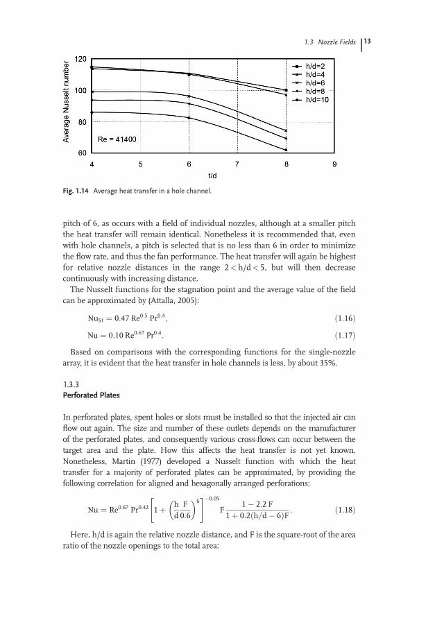
pitch of 6, as occurs with a field of individual nozzles, although at a smaller pitchthe heat transfer will remain identical. Nonetheless it is recommended that, evenwith hole channels, a pitch is selected that is no less than 6 in order to minimizethe flow rate, and thus the fan performance. The heat transfer will again be highestfor relative nozzle distances in the range 2<h/d< 5, but will then decreasecontinuously with increasing distance.The Nusselt functions for the stagnation point and the average value of the field
can be approximated by (Attalla, 2005):
NuSt ¼ 0:47 Re0:5 Pr0:4; ð1:16ÞNu ¼ 0:10 Re0:67 Pr0:4: ð1:17Þ
Based on comparisons with the corresponding functions for the single-nozzlearray, it is evident that the heat transfer in hole channels is less, by about 35%.
1.3.3Perforated Plates
In perforated plates, spent holes or slots must be installed so that the injected air canflow out again. The size and number of these outlets depends on the manufacturerof the perforated plates, and consequently various cross-flows can occur between thetarget area and the plate. How this affects the heat transfer is not yet known.Nonetheless, Martin (1977) developed a Nusselt function with which the heattransfer for a majority of perforated plates can be approximated, by providing thefollowing correlation for aligned and hexagonally arranged perforations:
Nu ¼ Re0:67 Pr0:42 1þ hd
F0:6
� �6" #�0:05
F1� 2:2 F
1þ 0:2 h=d� 6ð ÞF : ð1:18Þ
Here, h/d is again the relative nozzle distance, and F is the square-root of the arearatio of the nozzle openings to the total area:
Fig. 1.14 Average heat transfer in a hole channel.
1.3 Nozzle Fields 13

F ¼ffiffiffiffiffiffiffiffiffiffiffiffiffiffiffiAnozzles
Atotal
s: ð1:19Þ
For plates with equally distributed pitch t, it follows that
F ¼ffiffiffip
4
rdt: ð1:20Þ
The influence of the relative distance and the nozzle pitch is shown in Fig. 1.15,where heat transfer is seen to decrease continuously with the relative distance. Themaximum heat transfer occurs in the case of pitches in the range of 3 to 5,depending on the distance. The heat transfer is lower than that of an array ofindividual nozzles. As the maximum occurs at a smaller pitch than 6 (as for single-nozzle arrays), a higher flow rate must also be applied.Geers et al. (2008) have largely confirmed the correlation of Martin. Heikkil€a
and Milosavljevic (2002) concluded that the correlation provides slightly too-high values only when air temperature is above 400 �C. Huber and Viskanta(1994) provided a somewhat more simple correlation for pitches t/d� 4 right ofthe maximum (see Tab. 1.2), whereby the Nusselt number was seen to decreasecontinuously with the pitch.
1.3.4Nozzles for Cylindrical Bodies
For nonplanar bodies the curvature arises as an additional geometric parameter. Inthe following discussions, a cylindrical body is considered as the fundamental case.In Fig. 1.16, a cylinder of diameter D is shown, which is impinged from a slot of
Fig. 1.15 Influence of the pitch and the nozzle distance on the heat transfer for perforated plates.
14 1 Impinging Jet Drying

width s. With regards to the influence of the geometric parameters and theReynolds number, divergent results have occasionally been reported in theliterature. For example, Gori and Bossi (2003) and Chan et al. (2002) noted that amaximum in the heat and mass transfer occurred at a relative nozzle distance of h/s¼ 8, whereas Nada (2006) gave this maximum as between h/d¼ 4 and 6.McDaniel and Webb (2000) measured a maximum at h/d¼ 5, but only fromnozzles with rounded edges. In contrast, for sharp-edged nozzles the heat transferwas continuously decreased with distance. Olsson et al. (2004) also indicated adecreasing heat transfer with distance, but this was very moderate with anexponent of only �0.077. For all of these authors the influence of the distance wasweak. As noted previously for single nozzles and flat surfaces, a distance up tovalues of h/d¼ 5 had no effect, whereas heat transfer was slightly decreased athigher distances. The Nusselt functions given below are therefore based on adistance in the range 2�h/s� 8. The influence of the ratio D/s has been reportedby the various authors with exponents ranging from 0.03 to 0.22; consequently, inorder to provide a better comparison their results were approximated with anaverage exponent of 0.1.The exponents for the Reynolds number specified by the above-mentioned
authors have values from 0.4 to 0.82, depending partly on the geometric size.In Fig. 1.17, the measured Nusselt numbers of various authors are comparedusing D/s¼ 2 and h/s¼ 5 as examples. The length of the dotted linesrepresents the range of the investigated Reynolds numbers. The bold line withthe gradient 0.67 represents an average value; this line can be approximated in
Fig. 1.16 Flow to a cylinder from a slot nozzle.
1.3 Nozzle Fields 15

the range 2�h/s� 8 with
NuD ¼ 0:20 Re0:67D Pr0:4 D=sð Þ0:1: ð1:21ÞThe dimensionless numbers are formed with the cylinder diameter D:
NuD ¼ aDl
; ReD ¼ w Dn
: ð1:22Þ
The values of the Nusselt numbers are similar to those resulting from the Nusseltfunction corresponding to cross-flow of cylinders if the cross-flow length pDð Þ=2is used as a characteristic dimension in the Nusselt and Reynolds numbers.The Nusselt function can alternatively be formed with the slot width s as the
characteristic dimension resulting in
Nus ¼ 0:15 Re0:67s Pr0:4 D=sð Þ�0:23; ð1:23Þwith
Nus ¼ asl; Res ¼ ws
n: ð1:24Þ
1.4Summary of the Nusselt Functions
The Nusselt functions for the single nozzle are summarized in Tab. 1.1, and for thenozzle fields in Tab. 1.2. The Nusselt and Reynolds numbers are defined with theinner nozzle diameter d regarding round nozzles, and with the width s regardingslot nozzles. The exponent of the Reynolds number in correlations for the average
Fig. 1.17 Nusselt number dependent on the Reynolds number for cylinders with slot nozzles forD/s¼ 2 and h/s¼ 5.
16 1 Impinging Jet Drying

heat transfer in nozzle fields has various reported values ranging from 0.66 to 0.72.It is mostly a matter of choice which exponent is used for the approximation of datawithin the spread of the measurement results. In order to enhance comparability ofthe Nusselt functions, the measurement results of the various references wererespectively approximated by the exponent 0.67.
1.5Design of Nozzle Field
Based on the given Nusselt functions for the required heat transfer coefficient inEq. 1.9, nozzle arrays can now be designed. It is again assumed that the heat ispredominantly transferred for evaporation, while the enthalpy to heat up the drymaterial is again neglected. First, an array of individual nozzles will be consideredfor which a distinct maximum in the heat transfer results at a pitch of t¼ 6d. Thus,
Tab. 1.1 Nusselt functions for single nozzles.
Nozzle shape Nusselt function Scope Reference
Circular Stagnation point regionNud ¼ 0:72 Re0:5d Pr0:4
r/d�� 0.5; 2 � h=d � 5
Attalla and Specht(2009)
Slot Nus ¼ 0:70 Re0:5s Pr0:4 2 � h=s � 5 Vader et al. (1991)Circular Averaged values
Nud ¼ 0:12 Re0:67d Pr0:40 < r/d < 3 Adler (2004)
Tab. 1.2 Nusselt functions for nozzle fields impinging flat surfaces.
Arrays of individual nozzles (in-line or staggered):Stagnation point r=d � 1: Nud ¼ 0:82 Re0:5d Pr0:4
Average: Nud ¼ 0:16 Re0:67d Pr0:4
Pitch t/d¼ 6, Distance 2 � h=d � 5
Attalla and Specht (2009)
Hole channels:Stagnation point r=d � 1: Nud ¼ 0:47 Re0:5d Pr0:4
Average: Nud ¼ 0:10 Re0:67d Pr0:4
Pitch t/d� 6, Distance 2 � h=d � 4;Width sK=d � 2
Attalla and Specht (2009)
Perforated plates:
Nud ¼ Re0:67d Pr0:42 1þ hd
F0:6
� �6" #�0:05
F1� 2:2 F
1þ 0:2 h=d� 6ð ÞF
F ¼ffiffiffiffiffiffiffiffiffiffiffiffiffiffiffiAnozzles
Atotal
r, F round nozzleð Þ ¼
ffiffiffiffip
4
rdt
Pitch 1.4� t/d� 14, Distance 2�h/d� 12
Martin (1977)
Nud ¼ 0:43 Re0:67d Pr0:4 h=dð Þ�0:123 t=dð Þ�0:725
Pitch 4� t/d� 8, Distance 0.25�h/d� 6Huber and Viskanta (1994)
1.5 Design of Nozzle Field 17

for the heat transfer coefficient from Eq. 1.15 with Pr¼ 0.7, is obtained:
a ¼ 0:14l
n0:67w0:67d�0:33: ð1:25Þ
The material properties are to be formed with the average temperatureT0 þ TSð Þ=2. The specific energy consumption thus depends only on the threeparameters – _mv, d, and w – the influence of which must be calculated numerically.In Fig. 1.18, the specific energy consumption, as well as the air and product
temperatures, are shown as a function of the drying rate. As an example, avelocity of 50m s�1, a nozzle diameter of 5mm, and an ambient temperature of20 �C was used. The higher the drying rate, the more the air must be heated toachieve the enthalpy of evaporation because the velocity, and therefore the flowrate, remain constant. The air does not need to be heated for drying rates lessthan about 2 gm�2 s�1, as an ambient air temperature of 20 �C is sufficient.Consequently, the specific energy consumption will be zero. At higher dryingrates, the specific energy consumption is initially increased sharply and thenpasses through a maximum; however, the specific energy consumptiondecreases steadily thereafter.In Fig. 1.19, specific energy consumption is shown separately as a function of the
evaporation rate, with the nozzle diameter as a parameter. The nozzle exit velocityis assumed to be constant at 50m s�1. It is evident that the specific energyconsumption is less with smaller nozzles, with the maximum being displacedtowards higher evaporation rates. However, the lowest possible value of nozzlediameter is limited, first by the increase in production costs, and second throughthe minimum distance of the nozzle to the product. This distance should not begreater than approximately five-times the nozzle diameter; otherwise the heattransfer will be decreased. Rather, the smaller the nozzle the closer the field mustbe shifted towards the product.In Fig. 1.20, specific energy consumption is shown as a function of the drying
rate, with the nozzle discharge velocity as a parameter; as an example, a nozzle
Fig. 1.18 Specific energy consumption, air, andproduct temperature as a functionof thedrying rate.
18 1 Impinging Jet Drying
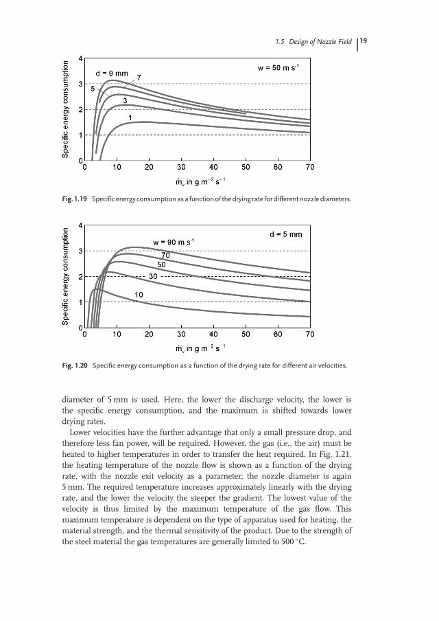
diameter of 5mm is used. Here, the lower the discharge velocity, the lower isthe specific energy consumption, and the maximum is shifted towards lowerdrying rates.Lower velocities have the further advantage that only a small pressure drop, and
therefore less fan power, will be required. However, the gas (i.e., the air) must beheated to higher temperatures in order to transfer the heat required. In Fig. 1.21,the heating temperature of the nozzle flow is shown as a function of the dryingrate, with the nozzle exit velocity as a parameter; the nozzle diameter is again5mm. The required temperature increases approximately linearly with the dryingrate, and the lower the velocity the steeper the gradient. The lowest value of thevelocity is thus limited by the maximum temperature of the gas flow. Thismaximum temperature is dependent on the type of apparatus used for heating, thematerial strength, and the thermal sensitivity of the product. Due to the strength ofthe steel material the gas temperatures are generally limited to 500 �C.
Fig. 1.19 Specific energy consumption as a functionof thedrying rate for differentnozzlediameters.
Fig. 1.20 Specific energy consumption as a function of the drying rate for different air velocities.
1.5 Design of Nozzle Field 19

Figures 1.22 and 1.23 show the specific energy consumption, the producttemperature and the gas temperature as a function of the nozzle diameter andof the discharge velocity, respectively, as an example for the drying rate10 gm�2 s�1. All three parameters decrease with decreasing nozzle diameter,while the gradients become larger with smaller nozzle diameters. Withdecreasing velocity the specific energy consumption also decreases and bothtemperatures are increased. The lower the velocity, the larger is the gradient ofvariation of the considered parameters.For hole channels, analogous results are valid, and a pitch of t¼ 6d is again
recommended. A larger pitch will result in a decrease in the heat transfer, whichwill remain constant with lower pitches; however, the number of nozzles and thusthe flow rate, will be increased. The specific energy consumption and the requiredgas temperatures are slightly higher for hole channels than for single-nozzle arrays,because the heat transfer is somewhat lower.
Fig. 1.21 Influence of the drying rate and the velocity on the required air temperature.
Fig. 1.22 Influence of the nozzle diameter.
20 1 Impinging Jet Drying

In the case of perforated plates the heat transfer is somewhat less but they are theeasiest to manufacture and consequently are commonly used. In Fig. 1.24, thespecific energy consumption, the air temperature and the temperature of thematerial are again shown as a function of the drying rate, with a pitch of t¼ 6d asan example. The values for the perforated plate are compared here with values forthe single-nozzle array. It is clear that, in order to achieve the same drying rate withperforated plates, higher air temperatures – and thus higher specific energyconsumptions – are required to compensate for the reduced heat transfer.Figure 1.25 shows the influence of the diameter on specific energy
consumption and both temperatures, using examples of drying rates of10 gm�2 s�1 and of 50 gm�2 s�1; the pitch is again t¼ 6d. When the drying rateis 10 gm�2 s�1, the specific energy consumption of the perforated plate isalmost 50% higher than that of the single-nozzle array. However, at a higherdrying rate of 50 gm�2 s�1 for diameters larger than 3mm, the material can no
Fig. 1.23 Influence of the air velocity.
Fig. 1.24 Comparison of single-nozzle array and perforated plate for different drying rates.
1.5 Design of Nozzle Field 21

longer be dried; otherwise, the air temperatures must be above 500 �C. Withregards to perforated plates, the heat transfer according to Fig. 1.15 alsodepends on the pitch and nozzle distance. Thus, the maximum heat transferwill occur with a pitch in the range of four, which is a smaller value than forsingle-nozzle arrays. Heat transfer will also depend on the nozzle distance, andincreases with decreasing distance. The influence of the pitch is shown forperforated plates in Fig. 1.26, where the pitch is with four smaller than beforeand with eight greater than before, while the diameter and velocity are heldconstant. With regards to the pitch of four, lower air temperatures will beneeded as the heat transfer will be stronger, although the flow rate will beincreased due to the larger number of perforations and, as a result, the specificenergy consumption will also increase. In terms of low energy consumption, alarge pitch is desirable; however, the maximum possible drying rates are limiteddue to increasing temperatures.Finally, the influence of the nozzle distance is shown in Fig. 1.27 where, the
lower the distance, the lower is the energy consumption. For a given airtemperature with lower distances, higher drying rates can be achieved.
Fig. 1.25 Influence of the nozzle diameter for two drying rates.
22 1 Impinging Jet Drying

1.6Conclusion
The highest convective heat transfer coefficients in drying processes can beachieved using nozzle fields, and drying is strongly intensified in such a field. As aconsequence, the heat transfer area, and therefore the size of the apparatus, can bereduced, saving investment costs.The energy required to heat the drying air decreases with smaller nozzle
diameters and slower outflow velocities, and consequently the operation costsare reduced. The lowest possible value of the nozzle diameter is, however,limited to ensure that the distance between the nozzle and material is notbelow four diameters. The lower the air velocity, the higher the hot airtemperature must be. The temperature of the hot air is limited to 500 �C dueto the strength of steel; however, the hot air temperature must normally bekept much lower in order to protect sensitive products against thermaldamage. The pitch of the nozzles has an optimum value of six diameters for
Fig. 1.26 Influence of the pitch for perforated plates at different drying rates.
Fig. 1.27 Influence of the nozzle–surface distance for perforated plates.
1.6 Conclusion 23

the heat transfer with regards to single-nozzle arrays and hole channels. Withregards to perforated plates, the optimum value for heat transfer occurs atpitches in the range of four, while the minimum for the specific energyconsumption is achieved with a nozzle pitch of between eight and ten.
Additional Notation Used in Chapter 1
D diameter of cylindrical drying body md inner diameter of nozzle mF square-root of nozzle opening area to total area �_H enthalpy flow rate J s�1
h nozzle distance from product mm exponent of Reynolds number �s slot width, thickness mt pitch between nozzles m
Subscripts
lo local values saturation (assumed product condition)st stagnation point/region0 outlet of heater (entrance of dryer)
References
Adler, W., 2004. Experimentelle Bestimmungdes W€arme€ubergangs bei der Prallstr€omung€uber einen hohen Reynoldszahlenbereichmittels Infrarot-Thermografie. Diss., Ottovon Guericke University Magdeburg,Germany.
Angioletti, M., Di Tommaso, R. M., Nino,E., Ruocco, G., 2003. Simultaneousvisualization of flow field and evaluationof local heat transfer by transitionalimpinging jets. Int. J. Heat Mass Transfer46: 1703–1713.
Attalla, M., 2005. Experimental investigation ofheat transfer characteristics from arrays offree impinging circular jets and hole
channels. Diss., Otto von GuerickeUniversity Magdeburg, Germany.
Attalla, M., Specht, E., 2009. Heat transfercharacteristics from in-line arrays of freeimpinging jets.Heat Mass Transfer 45(5):537–543.
Chan, T. L., Leung, C. W., Jambunathan, K.,Ashforth-Frost, S., Zhou, Y., Liu, J. H., 2002.Heat transfer characteristics of a slot jetimpinging on a semi-circular convex surface.Int. J. Heat Mass Transfer 45:993–1006.
Geers, L. F. G., Tummers, M. J., Bueninck, T.J., Hanjalic, K., 2008. Heat transfercorrelation for hexagonal and in-line arrays
24 1 Impinging Jet Drying

of impinging jets. Int. J. Heat Mass Transfer51: 5389–5399.
Gori, F., Bossi, L., 2003. Optimal slot height inthe jet cooling of a circular cylinder.Appl. Therm. Eng. 23: 859–870.
Heikkil€a, P., Milosavljevic, N., 2002.Investigation of impingement heat transfercoefficient at high temperatures. DryingTechnol. 20(1): 211–222.
Huber, A. M., Viskanta, R., 1994. Effect ofjet-jet spacing on convective heat transferto confined, impinging arrays ofaxisymmetric jets. Int. J. Heat MassTransfer 37: 2859–2869.
Martin, H., 1977. Heat and mass transferbetween impinging gas jets and solidsurface, in Advances in heat transfer, (eds J. R.Hartnett, T. F. Irvine), Academic Press, NewYork, USA, pp. 1–59.
McDaniel, C. S., Webb, B. W., 2000. Slot jetimpingement heat transfer from circularcylinders. Int. J. Heat Mass Transfer 42: 1975–1985.
Mujumdar, A. S. (ed.), 2007.Handbookof industrial drying, CRC Press, BocaRaton, USA.
Nada, S. A., 2006. Slot/slots air jet impingingcooling of a cylinder for different jets -cylinder configurations.Heat Mass Transfer43(2): 135–148.
Olsson, E. E. M., Ahrn�e, L. M., Tr€agardh, A. C.,2004. Heat transfer from a slot air jetimpinging on a circular cylinder. J. Food Eng.63: 393–401.
Vader, D. T., Incropera, F. P., Viskanta, R.,1991. Local convective heat transfer froma heated surface to an impinging, planarjet of water. Int. J. Heat Mass Transfer 34:611–623.
References 25


![REPORTOOCUM ETATIONPAOB - DTICcharacteristics of impinging jet sprays. Ingebo [6] quantified the drop-size distribution for heptane jets impinging at 90%, and obtained an empirical](https://img.pdfslide.us/doc/110x75/5f7eb6364693594f354d769d/reportoocum-etationpaob-dtic-characteristics-of-impinging-jet-sprays-ingebo-6.jpg)