Embed Size (px)
Citation preview
IEEE P1730/Dv2.0, January 2008
Copyright © 2008 IEEE. All rights reserved. This is an unapproved IEEE Standards Draft sponsored by SISO, subject to change.
IEEE P1730™/Dv2.0 1
Draft Recommended Practice for Distributed 2
Simulation Engineering and Execution Process 3
(DSEEP) 4
Prepared by the DSEEP Product Development Group of the 5
Simulation Interoperability Standards Organization (SISO) 6
Copyright © 2008 by the Institute of Electrical and Electronics Engineers, Inc. 7 Three Park Avenue 8 New York, New York 10016-5997, USA 9 All rights reserved. 10
Sponsored by the Simulation Interoperability Standards Organization (SISO) and the IEEE Computer 11 Society. 12
This document is an unapproved draft of a proposed IEEE Standard. As such, this document is subject to 13 change. USE AT YOUR OWN RISK! Because this is an unapproved draft, this document must not be 14 utilized for any conformance/compliance purposes. Permission is hereby granted for IEEE Standards 15 Committee participants to reproduce this document for purposes of IEEE standardization activities only. 16 Prior to submitting this document to another standards development organization for standardization 17 activities, permission must first be obtained from the Manager, Standards Licensing and Contracts, IEEE 18 Standards Activities Department. Other entities seeking permission to reproduce this document, in whole 19 or in part, must obtain permission from the Manager, Standards Licensing and Contracts, IEEE Standards 20 Activities Department. 21 22
IEEE Standards Activities Department Standards Licensing and Contracts 445 Hoes Lane, P.O. Box 1331 Piscataway, NJ 08855-1331, USA
SISO EXCOM P.O. Box 781238 Orlando, FL 32878-1238, USA
23

IEEE P1730/Dv2.0, January 2008
Copyright © 2008 IEEE. All rights reserved. This is an unapproved IEEE Standards Draft sponsored by SISO, subject to change. ii
Abstract: This document describes the Recommended Practice for Distributed Simulation 1 Engineering and Execution Process (DSEEP). The DSEEP is intended as a high-level process 2 framework into which the lower-level systems engineering practices native to any distributed 3 simulation user can, such as DIS, HLA and TENA, be easily integrated. 4 5 Keywords: M&S, Distributed Simulation, System Engineering Methodology, Process, HLA, DIS6

IEEE P1730/Dv2.0, January 2008
Copyright © 2008 IEEE. All rights reserved. This is an unapproved IEEE Standards Draft sponsored by SISO, subject to change. iii
Introduction 1
[This introduction is not part of IEEE P1730™/Dv2.0, IEEE Recommended Practice for Distributed 2 Simulation Engineering and Execution Process (DSEEP).] 3
Computer Modeling and Simulation (M&S) has long been an enabler of many key activities across a broad 4 spectrum of different user communities. At its core, M&S is all about the reduction of risk. That is, by 5 providing abstract representations of highly complex systems along with the operational environment in 6 which the system exists, users can gain an understanding of the performance and behavior of the system 7 that would not be achievable otherwise. Thus, the insight gained through careful and thoughtful 8 application of M&S assets provides an invaluable means of making wise decisions about how the system 9 should be designed, developed, and employed. 10
There is a wide variety of models and simulations in use today. Such tools are generally characterized by 11 their general class (live, virtual, or constructive) and by the level of detail that they support. While most 12 M&S tools are designed as standalone applications, recent advances in software and networking 13 technology has led to much greater use of distributed simulation environments. In such environments, the 14 unique functionalities offered by a selected set of disparate models and simulations are combined and 15 linked using high-speed networks and advanced simulation services to create an integrated system that 16 appears to users to be a single, very powerful simulation. 17
There are many different approaches to building distributed simulation environments that rely on a wide 18 variety of different protocols, middleware products, and data management schemes. The choice of which 19 systems engineering methodology works best in any given situation depends on several factors, such as the 20 class of application (e.g., analysis, test, training), the types of M&S assets being linked together, 21 VV&A/security concerns, cost/schedule constraints, and even the background and experience of the 22 development team. While considerable experimentation within the distributed simulation community has 23 driven the current wide range of modern, innovative distributed simulation development and execution 24 methodologies and supporting implementation mechanisms in use today, the proliferation of such 25 methodologies has made it more difficult to transition M&S assets (including the people that support them) 26 from one user domain to another, and in some cases, has become a barrier to interoperability across the 27 environments supported by different user domains employing different methodologies. 28
One means of addressing these problems is to compare the various approaches to distributed simulation 29 environments, and look for the common denominator. That is, determine if there are certain activities and 30 tasks that are universal across all communities of distributed simulation users, and capture these within a 31 common, unified process model. A common process would be quite valuable for several reasons: 32
There would be a common basis for comparison of different domain-specific methodologies. 33 That is, by identifying how the various methodologies are the same, it also identifies how they are 34 different, and thus facilitates the understanding of how and when one methodology should be used 35 versus another. 36
It would provide a common framework for different communities to describe their native systems 37 engineering practices. That is, by describing their engineering practices within the context of the 38 generalized activities and tasks in the common process model, they can better communicate with 39 and understand the approaches used by other communities that use this same process framework, 40 and help them to drive toward commonality in development approaches whenever possible. 41
It would provide a common language for building mixed-protocol simulation environments. That 42 is, in circumstances in which more than one protocol is required to meet all of the technical, cost, 43 and schedule constraints associated with the application, a common process model can help to 44 bridge the communications barriers that frequently occur between the users of different protocols, 45

IEEE P1730/Dv2.0, January 2008
Copyright © 2008 IEEE. All rights reserved. This is an unapproved IEEE Standards Draft sponsored by SISO, subject to change. iv
and helps to identify and establish the necessary agreements that must be made for such mixed-1 protocol environments to operate properly. 2
It would provide an effective "first read" to people that are new to the distributed simulation 3 community that want to learn and understand the high-level view of the current best practices in 4 the distributed simulation community before immersing themselves in the specific systems 5 engineering approach used within their own user domain. 6
This document describes the Recommended Practice for Distributed Simulation Engineering and Execution 7 Process (DSEEP). The purpose of this document is to describe a generalized process for building and 8 executing distributed simulation environments. It is not intended to replace the existing management and 9 systems design/development methodologies of user organizations, but rather to provide a high-level 10 framework for simulation environment construction and execution into which lower-level systems 11 engineering practices native to each individual application area can be easily integrated. In addition, the 12 DSEEP is not intended to be prescriptive, in that it does not specify a “one size fits all” process for all users 13 of distributed simulation. Rather, the DSEEP defines a generic, common-sense systems engineering 14 methodology that can and should be tailored to meet the needs of individual applications. 15
Although every distributed simulation application requires a basic agreement among all member 16 applications as to the systems engineering approach that will be used to develop and execute the simulation 17 environment, there can be significant variability in the degree of formality defined in the chosen process. 18 The primary driver for how much formality is required is the size and complexity of the application. For 19 example, in large complex applications with many distributed member applications, project control 20 requirements generally dictate the need for a rigidly defined, highly structured process to ensure proper 21 communication and coordination among all team members. In such environments, requirements and 22 associated schedules for delivery of supporting products are generally very explicit, as is the content and 23 format for documentation of these products. In smaller or less complex applications, a less structured 24 process with fewer constraints on the types, formats, and content of supporting products may be perfectly 25 reasonable and may have certain efficiency advantages as compared to a more formalized process. 26
Other secondary factors may also drive the process selected for a specific application. For instance, some 27 communities may have documentation requirements that are unique to their application area. In this case, 28 the activities required to produce these products must be accounted for in the overall process. The reuse 29 potential of these and other required products may also influence the nature and formality of the activities 30 that produce them. Another factor is the availability of reusable products and persistent development teams 31 as opportunities for shortcuts, whereby it may be possible to identify and take advantage of a more 32 streamlined, efficient development process. Finally, practical resource constraints (i.e., cost, schedule) may 33 dictate how certain activities are performed and how the associated products are produced and 34 documented. 35
In summary, it is recognized that the needs and requirements of the distributed simulation community are 36 quite diverse. The DSEEP is offered to the distributed simulation community as a means of identifying 37 today's best practices for the development and execution of distributed simulation environments, and for 38 identifying and addressing the various technical and managerial issues associated with implementation of 39 these practices. The DSEEP can and should be tailored as appropriate to address the unique issues, 40 requirements, and practical constraints of each individual application. It is expected that this framework 41 will provide a viable foundation for all distributed simulation applications and will assist the users in 42 defining the specific tasks and activities necessary to support their particular needs. 43
Patents 44
Attention is called to the possibility that implementation of this recommended practice may require use of 45 subject matter covered by patent rights. By publication of this recommended practice, no position is taken 46 with respect to the existence or validity of any patent rights in connection therewith. The IEEE shall not be 47 responsible for identifying patents or patent applications for which a license may be required to implement 48

IEEE P1730/Dv2.0, January 2008
Copyright © 2008 IEEE. All rights reserved. This is an unapproved IEEE Standards Draft sponsored by SISO, subject to change. v
an IEEE standard or for conducting inquiries into the legal validity or scope of those patents that are 1 brought to its attention. 2 3
Participants 4
At the time this draft recommended practice was completed, the DSEEP PDG working group had the 5 following membership: 6 7
Robert Lutz, Chair 8 Katherine L. Morse, Co-Vice Chair 9 Jean-Louis Igarza, Co-Vice Chair 10
Jake Borah, Secretary 11 Paul Gustavson, Drafting Group Editor 12
13 14 Isao Aoyama Joanne Atherton Jane Bachman Jake Borah* Derrick Briscoe Dannie Cutts* Klaas Jan de Kraker Bradford Dillman Hoang Doan Arren Dorman Mark Dumble Joey Fann Keith Ford Paul Gustavson* Frank Hill Wim Huiskamp Jean-Louis Igarza
Stephen Jones Fredrik Jonsson Michael Kipness Phil Landweer Jeremy Lanman Mike Lightner Reed Little Staffan Löf Bjorn Lofstrand* Max Lorenzo Paul Lowe* Van Lowe Robert Lutz James McCall* Ted Miller Bjorn Möller* Katherine Morse
Scott Newman David Osen Colin Petford Richard Reading Lawrence Root Peter Ross Chris Rouget Roy Scrudder Graham Shanks Steven Sheasby Petr Shlyaev Cam Tran Sarah Trbovich Douglas Wakefield Lucien Zalcman
15 * Represents member of the PDG Drafting Group 16 17 The following members of the balloting committee voted on this standard. Balloters may have voted for 18 approval, disapproval, or abstention. (To be provided by IEEE editor at time of publication.) 19

IEEE P1730/Dv2.0, January 2008
Copyright © 2008 IEEE. All rights reserved. This is an unapproved IEEE Standards Draft sponsored by SISO, subject to change. vi
1
This page left intentionally blank 2 3

IEEE P1730/Dv2.0, January 2008
Copyright © 2008 IEEE. All rights reserved. This is an unapproved IEEE Standards Draft sponsored by SISO, subject to change. vii
Table of Contents 1
Introduction ................................................................................................................................................... iii 2
Patents ............................................................................................................................................................iv 3
Participants ......................................................................................................................................................v 4
1. Overview .....................................................................................................................................................1 5
1.1 Scope .....................................................................................................................................................1 6
1.2 Purpose ..................................................................................................................................................1 7
2. References ...................................................................................................................................................1 8
3. Definitions and Acronyms...........................................................................................................................1 9
3.1 Definitions .............................................................................................................................................1 10
3.2 Acronyms ..............................................................................................................................................2 11
4. DSEEP: Top-Level View ............................................................................................................................2 12
5. DSEEP: Detailed View ...............................................................................................................................4 13
5.1 Step 1: Define Simulation Environment Objectives..............................................................................6 14
5.2 Step 2: Perform Conceptual Analysis....................................................................................................9 15
5.3 Step 3: Design Simulation Environment .............................................................................................13 16
5.4 Step 4: Develop Simulation Environment ...........................................................................................17 17
5.5 Step 5: Plan, Integrate, and Test Simulation Environment..................................................................22 18
5.6 Step 6: Execute Simulation Environment and Prepare Outputs ..........................................................26 19
5.7 Step 7: Analyze Data and Evaluate Results.........................................................................................28 20
6. Conclusion.................................................................................................................................................29 21
7. Bibliography..............................................................................................................................................30 22
Annex A: High Level Architecture (HLA) Process Overlay to the DSEEP ..........................................31 23
Introduction ...............................................................................................................................................31 24
Section 1: Terminology Mappings and Definitions (Specific Architecture / Methodology to DSEEP) ...31 25
Section 2: Global Mapping (Specific Architecture/Methodology to DSEEP) ..........................................32 26
Section 3: Detailed Mappings (Specific Architecture/Methodology to DSEEP) ......................................32 27

IEEE P1730/Dv2.0, January 2008
Copyright © 2008 IEEE. All rights reserved. This is an unapproved IEEE Standards Draft sponsored by SISO, subject to change. viii
Section 4: References (Annex-specific) ....................................................................................................35 1
Annex B: Distributed Interactive Simulation (DIS) Process Overlay to the DSEEP ............................37 2
Introduction ...............................................................................................................................................37 3
Section 1: Terminology Mappings and Definitions (Specific Architecture/Methodology to DSEEP) .....37 4
Section 2: Global Mapping (Specific Architecture/Methodology to DSEEP) ..........................................39 5
Section 3: Detailed Mappings (Specific Architecture/Methodology to DSEEP) ......................................41 6
Section 4: References (Annex-specific) ....................................................................................................45 7

IEEE P1730/Dv2.0, January 2008
Copyright © 2008 IEEE. All rights reserved. This is an unapproved IEEE Standards Draft sponsored by SISO, subject to change. 1
Draft Recommended Practice for 1
Distributed Simulation Engineering 2
and Execution Process (DSEEP) 3
Draft v2 4
1. Overview 5
1.1 Scope 6
This document defines the development and execution processes and procedures that should be followed 7 by users, developers, and managers of distributed simulation environments. It is not intended to replace 8 low-level management and systems engineering practices native to participating organizations, but is rather 9 intended as a higher-level framework into which such practices can be integrated and tailored for specific 10 uses. 11
1.2 Purpose 12
The purpose of this document is to describe a high-level process by which distributed simulation 13 environments can be developed and executed to meet the needs of a given user organization or sponsor. It 14 is expected that the guidelines provided in this document are generally relevant to and can support the 15 needs of most Modeling and Simulation (M&S) user communities and domains. 16
2. References 17
TBD. 18
3. Definitions and Acronyms 19
3.1 Definitions 20
The following terms and definitions shall apply throughout this document. 21
3.1.1 conceptual model: An abstraction of the real world that serves as a frame of reference for distributed 22 simulation development by documenting simulation-neutral views of important entities and their key 23 actions and interactions. The conceptual model describes what the simulation environment will represent, 24 the assumptions limiting those representations, and other capabilities needed to satisfy the user’s 25 requirements. Conceptual models are bridges between the real world, requirements, and design. 26
3.1.2 member: An application that is serving some defined role within a simulation environment. This 27 can include live, virtual, or constructive simulation assets, or can be supporting utility programs such as 28 data loggers or visualization tools. 29
IEEE P1730/Dv2.0, January 2008
Copyright © 2008 IEEE. All rights reserved. This is an unapproved IEEE Standards Draft sponsored by SISO, subject to change. 2
3.1.3 objective: The desired goals and results of the activity to be conducted in the distributed simulation 1 environment expressed in terms relevant to the organization(s) involved. 2
3.1.4 requirement: A statement that identifies a distributed simulation environment characteristic, 3 constraint, process, or product that is unambiguous and testable and that is necessary for a distributed 4 simulation environment to be acceptable for its intended use. 5
3.1.5 simulation environment: A named set of member applications along with a common information 6 exchange data model and set of agreements that are used as a whole to achieve some specific objective. 7
3.1.6 scenario: a. Description of an exercise. It is part of the session database that configures the units and 8 platforms and places them in specific locations with specific missions [B1]; b. An initial set of conditions 9 and time line of significant events imposed on trainees or systems to achieve exercise objectives [B2]. 10
3.2 Acronyms 11
The following acronyms pertain to this recommended practice. 12
BOM Base Object Model 13 CASE Computer Aided Software Engineering 14 COTS Commercial Off-the-Shelf 15 CPU Central Processing Unit 16 DIS Distributed Interactive Simulation 17 DSEEP Distributed Simulation Engineering and Execution Process 18 FOM Federation Object Model 19 GOTS Government Off-the-Shelf 20 HLA High Level Architecture 21 IEDM Information Exchange Data Model 22 IEEE Institute for Electrical and Electronics Engineers 23 LAN Local Area Network 24 M&S Modeling and Simulation 25 TENA Test and Training Enabling Architecture 26 VV&A Verification, Validation, and Accreditation 27 WAN Wide Area Network 28
4. DSEEP: Top-Level View 29
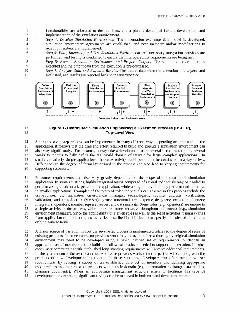
Because of the great diversity among the needs of the distributed simulation user community, there is a 30 recognized desire to avoid mandating unnecessary constraints on how such environments are developed 31 and executed, and generally to ensure a high degree of flexibility with regard to how supporting processes 32 are structured. For instance, the types and sequence of low-level activities required to develop and execute 33 analysis-oriented simulation environments is likely to be quite different from those required to develop and 34 execute distributed training exercises. However, at a more abstract level, it is possible to identify a 35 sequence of seven very basic steps that all distributed simulation applications will need to follow to 36 develop and execute their simulation environments. Figure 1 illustrates each of these steps and is 37 summarized below: 38 39 — Step 1: Define Simulation Environment Objectives. The user, the sponsor, and the development team 40
define and agree on a set of objectives and document what must be accomplished to achieve those 41 objectives. 42
— Step 2: Perform Conceptual Analysis. Based on the characteristics of the problem space, an 43 appropriate representation of the real world domain is developed. 44
— Step 3: Design Simulation Environment. Existing members that are suitable for reuse are identified, 45 design activities for member modifications and/or new members are performed, required 46
IEEE P1730/Dv2.0, January 2008
Copyright © 2008 IEEE. All rights reserved. This is an unapproved IEEE Standards Draft sponsored by SISO, subject to change. 3
functionalities are allocated to the members, and a plan is developed for the development and 1 implementation of the simulation environment. 2
— Step 4: Develop Simulation Environment. The information exchange data model is developed, 3 simulation environment agreements are established, and new members and/or modifications to 4 existing members are implemented. 5
— Step 5: Plan, Integrate, and Test Simulation Environment. All necessary integration activities are 6 performed, and testing is conducted to ensure that interoperability requirements are being met. 7
— Step 6: Execute Simulation Environment and Prepare Outputs. The simulation environment is 8 executed and the output data from the execution is pre-processed. 9
— Step 7: Analyze Data and Evaluate Results. The output data from the execution is analyzed and 10 evaluated, and results are reported back to the user/sponsor. 11
Corrective Actions / Iterative Development
65431
Perform Conceptual
Analysis
2
Analyze Data and Evaluate Results
7
DefineSimulation
Environment Objectives
DesignSimulation
Environment
DevelopSimulation
Environment
Plan,Integrate, and Test
SimulationEnvironment
ExecuteSimulation
Environment and Prepare
Outputs
Figure 1- Distributed Simulation Engineering & Execution Process (DSEEP), 12 Top-Level View 13
Since this seven-step process can be implemented in many different ways depending on the nature of the 14 application, it follows that the time and effort required to build and execute a simulation environment can 15 also vary significantly. For instance, it may take a development team several iterations spanning several 16 weeks to months to fully define the real world domain of interest for large, complex applications. In 17 smaller, relatively simple applications, the same activity could potentially be conducted in a day or less. 18 Differences in the degree of formality desired in the process can also lead to varying requirements for 19 supporting resources. 20
Personnel requirements can also vary greatly depending on the scope of the distributed simulation 21 application. In some situations, highly integrated teams composed of several individuals may be needed to 22 perform a single role in a large, complex application, while a single individual may perform multiple roles 23 in smaller applications. Examples of the types of roles individuals can assume in this process include the 24 user/sponsor; the simulation environment manager; technologists; security analysts; verification, 25 validation, and accreditation (VV&A) agents; functional area experts; designers; execution planners; 26 integrators; operators; member representatives; and data analysts. Some roles (e.g., operators) are unique to 27 a single activity in the process, while others are more pervasive throughout the process (e.g., simulation 28 environment manager). Since the applicability of a given role (as well as the set of activities it spans) varies 29 from application to application, the activities described in this document specify the roles of individuals 30 only in generic terms. 31
A major source of variation in how the seven-step process is implemented relates to the degree of reuse of 32 existing products. In some cases, no previous work may exist, therefore a thoroughly original simulation 33 environment may need to be developed using a newly defined set of requirements to identify an 34 appropriate set of members and to build the full set of products needed to support an execution. In other 35 cases, user communities with established long-standing requirements will receive additional requirements. 36 In this circumstance, the users can choose to reuse previous work, either in part or whole, along with the 37 products of new developmental activities. In these situations, developers can often meet new user 38 requirements by reusing a subset of an established core set of members and defining appropriate 39 modifications to other reusable products within their domain (e.g., information exchange data models, 40 planning documents). When an appropriate management structure exists to facilitate this type of 41 development environment, significant savings can be achieved in both cost and development time. 42
IEEE P1730/Dv2.0, January 2008
Copyright © 2008 IEEE. All rights reserved. This is an unapproved IEEE Standards Draft sponsored by SISO, subject to change. 4
The remainder of this document describes a structured, systems engineering approach to simulation 1 environment development and execution known as the Distributed Simulation Engineering and Execution 2 Process (DSEEP). The seven-step process provides a top-level view of the DSEEP, while the DSEEP itself 3 describes a decomposition of each of the seven major steps into a set of interrelated lower-level activities 4 and supporting information resources. Since the needs of distributed simulation users range from “first 5 use” applications to experienced users, the DSEEP makes no assumptions about the existence of an 6 established core set of members or the up-front availability of reusable products. Although the intention is 7 to define a comprehensive, generalized framework for the construction and execution of distributed 8 simulation environments, it is important to recognize that users of this process model will normally need to 9 adjust and modify the DSEEP as appropriate to address the unique requirements and constraints of their 10 particular application area. 11
5. DSEEP: Detailed View 12
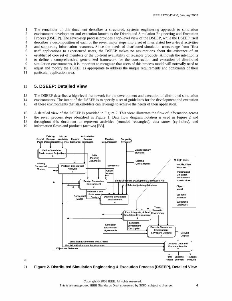
The DSEEP describes a high-level framework for the development and execution of distributed simulation 13 environments. The intent of the DSEEP is to specify a set of guidelines for the development and execution 14 of these environments that stakeholders can leverage to achieve the needs of their application. 15
A detailed view of the DSEEP is provided in Figure 2. This view illustrates the flow of information across 16 the seven process steps identified in Figure 1. Data flow diagram notation is used in Figure 2 and 17 throughout this document to represent activities (rounded rectangles), data stores (cylinders), and 18 information flows and products (arrows) [B3]. 19
Define SimulationEnvironment Objectives
1
Perform ConceptualAnalysis
2
Design SimulationEnvironment
3
Develop SimulationEnvironment
4
Execute Simulation Environment
& Prepare Outputs6
Plan, Integrate, & TestSimulation Environment
5
Analyze Data andEvaluate Results
7
Info onAvailable
ResourcesOverall Plans
ExistingDomain
Descriptions
Initial Planning
Documents
Objectives StatementSimulation Environment Requirements
Scenario(s)
Conceptual Model
Simulation Environment Test Criteria
Member & SimEnvironment
Designs
Sim Environment Development & Execution Plan
Derived Outputs
TestedSimulation
Environment
Execution Environment Description
SimulationEnvironment Agreements
ReusableProducts
LessonsLearned
FinalReport
Existing Scenarios
Authoritative Domain
Information
ExistingConceptual
Models
MemberDocumentation
ObjectModels
List of Selected (existing) Members
Data Dictionary Elements
ExistingObject Models
SupportingResources
ScenarioInstances
Object Model
Modified/NewMembers
SupportingDatabases
ImplementedSimulationEnvironmentInfrastructure
Multiple Items:
Define SimulationEnvironment Objectives
1
Perform ConceptualAnalysis
2
Perform ConceptualAnalysis
2
Design SimulationEnvironment
3
Design SimulationEnvironment
3
Develop SimulationEnvironment
4
Develop SimulationEnvironment
4
Execute Simulation Environment
& Prepare Outputs6
Plan, Integrate, & TestSimulation Environment
5
Plan, Integrate, & TestSimulation Environment
5
Analyze Data andEvaluate Results
7
Analyze Data andEvaluate Results
7
Info onAvailable
ResourcesOverall Plans
ExistingDomain
Descriptions
Initial Planning
Documents
Objectives StatementSimulation Environment Requirements
Scenario(s)
Conceptual Model
Simulation Environment Test Criteria
Member & SimEnvironment
Designs
Sim Environment Development & Execution Plan
Derived Outputs
TestedSimulation
Environment
Execution Environment Description
SimulationEnvironment Agreements
ReusableProducts
LessonsLearned
FinalReport
Existing Scenarios
Authoritative Domain
Information
ExistingConceptual
Models
MemberDocumentation
ObjectModels
List of Selected (existing) Members
Data Dictionary Elements
ExistingObject Models
SupportingResources
ScenarioInstances
Object Model
Modified/NewMembers
SupportingDatabases
ImplementedSimulationEnvironmentInfrastructure
Multiple Items:
20
Figure 2- Distributed Simulation Engineering & Execution Process (DSEEP), Detailed View 21

IEEE P1730/Dv2.0, January 2008
Copyright © 2008 IEEE. All rights reserved. This is an unapproved IEEE Standards Draft sponsored by SISO, subject to change. 5
The following subsections describe the lower-level activities associated with each of the seven major 1 development and execution steps. A tabular view of the activities inherent to each major step is provided in 2 Table 1. Each activity description includes potential inputs and outputs of that activity and a representative 3 list of recommended tasks. Graphical illustrations of the interrelationships among the activities within each 4 step are also provided. Whenever outputs from one DSEEP activity represent a major input to one or more 5 other activities, the arrow labels explicitly identify the activities that use these outputs. The arrow labels 6 also identify the activities that produce inputs. However, there is a presumption embodied within the 7 DSEEP that once a product has been created, it will be available for all subsequent activities, even though 8 the product may not be shown as a major input or identified as an input in the activity description. 9 Additionally, once a product is developed, the product may be modified or updated by subsequent 10 activities without such modifications being explicitly identified either as a task or output. Input and output 11 arrows without activity number labels are those in which the information originates from outside or is used 12 outside the scope of the DSEEP. 13
Although many of the activities represented in the DSEEP diagram appear highly sequential, the intention 14 is not to suggest a strict waterfall approach to development and execution. Rather, this process illustration 15 is simply intended to highlight the major activities that occur during development and execution and 16 approximately when such activities are first initiated relative to other development activities. In fact, 17 experience has shown that many of the activities shown in Figure 2 as sequential are actually cyclic and/or 18 concurrent, as was indicated earlier in Figure 1 via the dotted feedback arrows. In general, the lower level 19 activities will be conducted in the order implied by the information flow between these activities, but the 20 actual timing of these activities is not absolute and is dependent upon the systems engineering practices 21 actually being used. 22
23
Table 1-A Tabular View of the DSEEP 24
(1) Define
Simulation Environment Objectives
(2) Perform
Conceptual Analysis
(3) Design
Simulation Environment
(4) Develop
Simulation Environment
(5) Plan, Integrate,
and Test Simulation
Environment
(6) Execute
Simulation Environment and Prepare
Outputs
(7)
Analyze Data and Evaluate Results
Identify User/Sponsor
Needs
Develop Objectives
Develop Scenario
Develop
Conceptual Model
Develop
Simulation Environment Requirements
Select Members
Prepare
Simulation Environment
Design
Prepare Plan
Develop Information
Exchange Data Model
Establish
Simulation Environment Agreements
Implement Member Designs
Implement Simulation
Environment Infrastructure
Plan Execution
Integrate
Simulation Environment
Test
Simulation Environment
Execute Simulation
Environment
Prepare Simulation
Environment Outputs
Analyze Data
Evaluate
and Feedback Results
25
26

IEEE P1730/Dv2.0, January 2008
Copyright © 2008 IEEE. All rights reserved. This is an unapproved IEEE Standards Draft sponsored by SISO, subject to change. 6
Users of the DSEEP should be aware that the activities described in this document, while being generally 1 applicable to most distributed simulation environments, are intended to be tailored to meet the needs of 2 each individual application. For example, DSEEP users should not feel constrained by the products 3 explicitly identified in this document, but rather should produce whatever additional documentation is 4 necessary to support their application. Specific tailorings of the DSEEP based on the native systems 5 engineering processes inherent to certain widely-used distributed simulation architectures (DIS, HLA) are 6 included as annexes to this document. In general, the recommended practices provided in this document 7 should be used as a starting point for developing the most appropriate approach to development and 8 execution for the intended application. 9
5.1 Step 1: Define Simulation Environment Objectives 10
The purpose of step 1 of the DSEEP is to define and document a set of needs that are to be addressed 11 through the development and execution of a simulation environment and to transform these needs into a 12 more detailed list of specific objectives for that environment. 13
Figure 3 illustrates the key activities in this step of the DSEEP. In this diagram (and all subsequent 14 diagrams in this section), each individual activity is labeled by a number designation (X.Y) to show 15 traceability between the activity (Y) and the step (X) in the seven-step process to which the activity is 16 associated. The activity number in these diagrams is intended only as an identifier and does not prescribe a 17 particular ordering. The subsections that follow describe each of these activities. 18
Needs Statement
Objectives Statement2.1,2.2,2.3,3.1,7.1,7.2
Program Goals
Info on Available
Resources
Initial Planning Documents 3.3
Existing Domain
Descriptions
Identify User/Sponsor Needs
1.1
Conduct Initial Planning
1.3
Develop Objectives
1.2
Needs Statement
Objectives Statement2.1,2.2,2.3,3.1,7.1,7.2
Program Goals
Info on Available
Resources
Initial Planning Documents 3.3
Existing Domain
Descriptions
Identify User/Sponsor Needs
1.1
Identify User/Sponsor Needs
1.1
Conduct Initial Planning
1.3
Conduct Initial Planning
1.3
Develop Objectives
1.2
Develop Objectives
1.2
Figure 3-Define Simulation Environment Objectives (Step 1) 19
5.1.1 Activity 1.1 Identify User/Sponsor Needs 20
The primary purpose of this activity is to develop a clear understanding of the problem to be addressed by 21 the simulation environment. The needs statement may vary widely in terms of scope and degree of 22 formalization. It should include, at a minimum, high-level descriptions of critical systems of interest, initial 23 estimates of required fidelity and required behaviors for simulated entities, key events that must be 24 represented in the scenario, and output data requirements. In addition, the needs statement should indicate 25 the resources that will be available to support the simulation environment (e.g., funding, personnel, tools, 26 facilities) and any known constraints that may affect how the simulation environment is developed (e.g., 27 required participants, due dates, site requirements, and security requirements). In general, the needs 28 statement should include as much detail and specific information as is possible at this early stage of the 29 DSEEP. 30

IEEE P1730/Dv2.0, January 2008
Copyright © 2008 IEEE. All rights reserved. This is an unapproved IEEE Standards Draft sponsored by SISO, subject to change. 7
An explicit and unambiguous statement of user/sponsor needs is critical to achieving clear communication 1 of intent among the developers of the simulation environment. Failure to establish a common 2 understanding of the required product can result in costly rework in later stages of the DSEEP. 3
5.1.1.1 Activity Inputs 4
The potential inputs to this activity include the following. Neither this list of inputs, nor any subsequent 5 lists of inputs, is meant to be completely exhaustive, nor are all mandatory for all simulation environments. 6 7 — Program goals (from the stakeholder’s perspective) 8 — Existing domain descriptions 9 — Information on available resources 10
5.1.1.2 Recommended Tasks 11
The potential tasks for this activity include the following. Neither this list of tasks, nor any subsequent lists 12 of tasks, is meant to be completely exhaustive, nor are all mandatory for all simulation environments. 13 14 — Analyze the program goals to identify the specific purpose and objective(s) that motivate 15
development and execution of a simulation environment. 16 — Identify available resources and known development and execution constraints. 17 — Document the information listed above in a needs statement. 18
5.1.1.3 Activity Outcomes 19
The potential outcomes for this activity include the following. Neither this list of outcomes, nor any 20 subsequent lists of outcomes, is meant to be completely exhaustive, nor are all mandatory for all simulation 21 environments. 22 23 — Needs statement, including: 24
— Purpose of the simulation environment 25 — Identified needs (e.g., domain area/issue descriptions, high level descriptions of critical 26
systems of interest, initial estimates of required fidelity, and required behaviors for simulated 27 players) 28
— Key events that must be represented in a scenario 29 — Output data requirements 30 — Resources that will be available to support the simulation environment (e.g. funding, 31
personnel, tools, facilities) 32 — Any known constraints which may affect how the simulation environment is developed and 33
executed (e.g., due dates, security requirements) 34
5.1.2 Activity 1.2 Develop Objectives 35
The purpose of this activity is to refine the needs statement into a more detailed set of specific objectives 36 for the simulation environment. The objectives statement is intended as a foundation for generating explicit 37 simulation requirements, i.e., translating high-level user/sponsor expectations into more concrete, 38 measurable goals. This activity requires close collaboration between the user/sponsor of the simulation 39 environment and the development team to ensure that the original needs statement is properly analyzed and 40 interpreted correctly, and that the resulting objectives are consistent with the stated needs. 41
Early assessments of feasibility and risk should also be performed as part of this activity. In particular, 42 certain objectives may not be achievable given practical constraints (such as cost, schedule, availability of 43 personnel or facilities) or even limitations on the state-of-the-art of needed technology. Early identification 44 of such issues and consideration of these limitations and constraints in the Objectives Statement will set 45 appropriate expectations for the development and execution effort. 46

IEEE P1730/Dv2.0, January 2008
Copyright © 2008 IEEE. All rights reserved. This is an unapproved IEEE Standards Draft sponsored by SISO, subject to change. 8
Finally, the issue of tool selection to support scenario development, conceptual analysis, V&V, test 1 activities, and configuration management should be addressed before the Develop Objectives activity is 2 concluded. These decisions are made by the development team on the basis of tool availability, cost, 3 applicability to the given application, and the personal preferences of the participants. The ability of a 4 given set of tools to exchange information is also an important consideration. 5
5.1.2.1 Activity Inputs 6
Potential inputs to this activity include the following: 7 8 — Needs statement 9
5.1.2.2 Recommended Tasks 10
Potential tasks for this activity include the following: 11 12 — Analyze the needs statement 13 — Define and document a prioritized set of objectives, consistent with the needs statement 14 — Assess feasibility and risk, and incorporate into objectives statement 15 — Meet with the sponsor to review the objectives, and reconcile any differences 16 — Define and document an initial development and execution plan for the simulation environment 17 — Identify potential tools to support the initial plan 18
5.1.2.3 Activity Outcomes 19
Potential outcomes for this activity include the following: 20 21 — Objectives statement, including: 22
— Potential solution approaches and rationale for the selection of a simulation environment as 23 the best approach 24
— A prioritized list of measurable objectives for the simulation environment 25 — A high-level description of key simulation environment characteristics (repeatability, 26
portability, time management approach, availability, etc.) 27 — Domain context constraints or preferences, including object actions/relationships, 28
geographical regions, and environmental conditions 29 — Identification of execution constraints to include functional (e.g. execution control 30
mechanisms), technical (e.g. site, computational and network operations, health/performance 31 monitoring capabilities), economic (e.g. available funding), and political (e.g. organizational 32 responsibilities) 33
— Identification of security needs, including probable security level and possible designated 34 approval authority (or authorities, if a single individual is not possible) 35
— Identification of key evaluation measures to be applied to the simulation environment 36 37
5.1.3 Activity 1.3 Conduct Initial Planning 38
The purpose of this activity is to establish a preliminary development and execution plan. The intent is to 39 translate the Objectives Statement, along with the associated risk and feasibility assessments, into an initial 40 plan with sufficient detail to effectively guide early design activities. The plan may effectively include 41 multiple plans, and should cover such considerations as VV&A, configuration management, and security. 42 The plan should also address supporting tools for early DSEEP activities, based on factors such as 43 availability, cost, applicability to the given application, ability to exchange data with other tools, and the 44 personal preferences of the development team. 45
The plan should also define a high-level schedule of key development and execution events, and provide 46 additional scheduling detail for all pre-development (i.e. prior to Step 4) activities. Note that the initial 47

IEEE P1730/Dv2.0, January 2008
Copyright © 2008 IEEE. All rights reserved. This is an unapproved IEEE Standards Draft sponsored by SISO, subject to change. 9
plan will be updated and extended as appropriate in subsequent development phases as additional 1 knowledge and experience is accumulated throughout the evolution of the distributed simulation design 2 (see Activity 3.3). 3
5.1.3.1 Activity Inputs 4
Potential inputs to this activity include the following: 5 6 — Program Goals 7 — Objectives statement 8
5.1.3.2 Recommended Tasks 9
Potential tasks for this activity include the following: 10 11 — Define and document an initial development and execution plan for the simulation environment 12 — Identify potential tools to support the initial plan 13
5.1.3.3 Activity Outcomes 14
Potential outcomes for this activity include the following: 15 16 — Initial versions of planning documents, including: 17
— Development and execution plan for the simulation environment showing an approximate 18 schedule and major milestones 19
— Estimates of needed equipment, facilities, and data 20 — VV&A, test, configuration management, and security plans 21 — Tool selection to support scenario development, conceptual analysis, V&V, and configuration 22
management 23
5.2 Step 2: Perform Conceptual Analysis 24
The purpose of this step of the DSEEP is to develop an appropriate representation of the real world domain 25 that applies to the defined problem space and to develop the appropriate scenario. It is also in this step that 26 the objectives for the simulation environment are transformed into a set of highly specific requirements that 27 will be used in during design, development, testing, execution, and evaluation. Figure 4 illustrates the key 28 activities in this step of the DSEEP. The subsections that follow describe each of these activities in detail. 29

IEEE P1730/Dv2.0, January 2008
Copyright © 2008 IEEE. All rights reserved. This is an unapproved IEEE Standards Draft sponsored by SISO, subject to change. 10
Existing Scenarios
Scenarios 3.2,4.2
Conceptual Model 2.1,2.3,3.1,3.2,4.1,4.2
Simulation Environment Requirements 3.2,3.3,4.2,7.2
ObjectivesStatement
1.2
Simulation Environment Test Criteria 3.3,5.3,7.2
Existing Conceptual
Models
Authoritative Domain
Information
Develop Scenario
2.1
DevelopConceptual Model
2.2
Develop Simulation EnvironmentRequirements
2.3Scenario Database
Authoritative Resources
(New) Scenario(s)
Existing Scenarios
Scenarios 3.2,4.2
Conceptual Model 2.1,2.3,3.1,3.2,4.1,4.2
Simulation Environment Requirements 3.2,3.3,4.2,7.2
ObjectivesStatement
1.2
Simulation Environment Test Criteria 3.3,5.3,7.2
Existing Conceptual
Models
Authoritative Domain
Information
Develop Scenario
2.1
DevelopConceptual Model
2.2
DevelopConceptual Model
2.2
Develop Simulation EnvironmentRequirements
2.3
Develop Simulation EnvironmentRequirements
2.3Scenario DatabaseScenario Database
Authoritative Resources
Authoritative Resources
(New) Scenario(s)
Figure 4-Perform Conceptual Analysis (Step 2) 1
5.2.1 Activity 2.1 Develop Scenario 2
The purpose of this activity is to develop a functional specification of the scenario. Depending on the needs 3 of the simulation environment, the scenario may actually include multiple scenarios, each consisting of one 4 or more temporally ordered sets of events and behaviors (i.e., vignettes). The primary input to this activity 5 is the domain constraints specified in the objectives statement (step 1), although existing scenario databases 6 may also provide a reusable starting point for scenario development. Where appropriate, authoritative 7 sources for descriptions of major entities and their capabilities, behavior and relationships should be 8 identified prior to scenario construction. A scenario includes the types and numbers of major entities that 9 must be represented within the simulation environment, a functional description of the capabilities, 10 behavior, and relationships between these major entities over time, and a specification of relevant 11 environmental conditions that impact or are impacted by entities in the simulation environment. Initial 12 conditions (e.g., geographical positions for physical objects), termination conditions, and specific 13 geographic regions should also be provided. The product of this activity is a scenario or set of scenarios, 14 which provides a bounding mechanism for conceptual modeling activities. 15
The presentation style used during scenario construction is at the discretion of the simulation environment 16 developers. Textual scenario descriptions, event-trace diagrams, and graphical illustrations of geographical 17 positions for physical objects and communication paths all represent effective means of conveying scenario 18 information. Software tools that support scenario development can generally be configured to produce 19 these presentation forms. Reuse of existing scenario databases may also facilitate the scenario development 20 activity. 21
5.2.1.1 Activity Inputs 22
Potential inputs to this activity include the following: 23 24 — Objectives statement 25 — Existing scenarios 26 — Conceptual model 27 — Authoritative domain information 28
5.2.1.2 Recommended Tasks 29
Potential tasks for this activity include the following: 30

IEEE P1730/Dv2.0, January 2008
Copyright © 2008 IEEE. All rights reserved. This is an unapproved IEEE Standards Draft sponsored by SISO, subject to change. 11
1 — Choose the appropriate tool/technique for development and documentation of the scenario(s). 2 — Using authoritative domain information, identify the entities, behaviors, and events that need to be 3
represented in the scenario(s). 4 — Define one or more representative vignettes that, once executed, will produce the data necessary to 5
achieve the objectives of the simulation environment. 6 — Define geographic areas of interest. 7 — Define environmental conditions of interest. 8 — Define initial conditions and termination conditions for the scenario(s). 9 — Ensure that an appropriate scenario (or scenario set) has been selected, or if new scenario 10
information is to be developed, ensure with the stakeholder that the new scenario(s) will be 11 acceptable. 12
5.2.1.3 Activity Outcomes 13
Potential outcomes for this activity include the following: 14 15 — Scenario(s), including: 16
— Types and numbers of major entities/objects that must be represented within the simulation 17 environment 18
— Description of entity/object capabilities, behaviors, and relationships 19 — Event timelines 20 — Geographical region(s) 21 — Natural environment condition(s) 22 — Initial conditions 23 — Termination conditions 24
5.2.2 Activity 2.2 Develop Conceptual Model 25
During this activity, the development team produces a conceptual representation of the intended problem 26 space based on their interpretation of user needs and sponsor objectives. The product resulting from this 27 activity is known as a conceptual model (see Figure 4). The conceptual model provides an implementation-28 independent representation that serves as a vehicle for transforming objectives into functional and 29 behavioral descriptions for system and software designers. The model also provides a crucial traceability 30 link between the stated objectives and the eventual design implementation. This model can be used as the 31 structural basis for many design and development activities (including scenario development) and can 32 highlight correctable problems early in the development of the simulation environment when properly 33 validated by the user/sponsor. 34
The conceptual model starts as a description of the entities and actions that need to be included in the 35 simulation environment in order to achieve all stated objectives. At this point, these entities and actions are 36 described without any reference to the specific simulations that will be used in the application. The 37 conceptual model also contains an explanatory listing of the assumptions and limitations, which bound the 38 model. In later steps of the DSEEP, the conceptual model transitions through additional enhancement into a 39 reference product suitable for the design of the simulation environment. 40
The early focus of conceptual model development is to identify relevant entities within the domain of 41 interest, to identify static and dynamic relationships between entities, and to identify the behavioral and 42 transformational (algorithmic) aspects of each entity. Static relationships can be expressed as ordinary 43 associations, or as more specific types of associations such as generalizations (“is-a” relationships) or 44 aggregations (“part-whole” relationships). Dynamic relationships should include (if appropriate) the 45 specification of temporally ordered sequences of entity interactions with associated trigger conditions. 46 Entity characteristics (attributes) and interaction descriptors (parameters) may also be identified to the 47 extent possible at this early stage of the process. While a conceptual model may be documented using 48 differing notations, it is important that the conceptual model provides insight into the real world domain. 49
IEEE P1730/Dv2.0, January 2008
Copyright © 2008 IEEE. All rights reserved. This is an unapproved IEEE Standards Draft sponsored by SISO, subject to change. 12
The conceptual model needs to be carefully evaluated before the next step (Design Simulation 1 Environment) is begun, including a review of key processes and events by the user/sponsor to ensure the 2 adequacy of the domain representation. Revisions to the original objectives and conceptual model may be 3 defined and implemented as a result of this feedback. As the conceptual model evolves, it is transformed 4 from a general representation of the real world domain to a more specific articulation of the capabilities of 5 the simulation environment as constrained by the members of the simulation environment and available 6 resources. The conceptual model will serve as a basis for many later development activities such as 7 member selection and simulation environment design, implementation, test, evaluation, and validation. 8
5.2.2.1 Activity Inputs 9
Potential inputs to this activity include the following: 10 11 — Objectives statement 12 — Authoritative domain information 13 — Scenario(s) 14 — Existing conceptual models 15
5.2.2.2 Recommended Tasks 16
Potential tasks for this activity include the following: 17 18 — Choose the technique and format for development and documentation of the conceptual model. 19 — Identify and describe all relevant entities within the domain of interest. 20 — Define static and dynamic relationships between identified entities. 21 — Identify events of interest within the domain, including temporal relationships. 22 — Document the conceptual model and related decisions. 23 — Working with stakeholders, verify the contents of the conceptual model. 24
5.2.2.3 Activity Outcomes 25
Potential outcomes for this activity include the following: 26 27 — Conceptual model 28
5.2.3 Activity 2.3 Develop Simulation Environment Requirements 29
As the conceptual model is developed, it will lead to the definition of a set of detailed requirements for the 30 simulation environment. These requirements, based on the original objectives statement (step 1), should be 31 directly testable and should provide the implementation level guidance needed to design and develop the 32 simulation environment. The requirements should consider the specific execution management needs of all 33 users, such as execution control and monitoring mechanisms, data logging, etc. Such needs may also 34 impact the scenario developed in activity 2.1. The simulation environment requirements should also 35 explicitly address the issue of fidelity, so that fidelity requirements can be considered during selection of 36 simulation environment members. In addition, any programmatic or technical constraints on the simulation 37 environment should be refined and described to the degree of detail necessary to guide implementation 38 activities. 39
5.2.3.1 Activity Inputs 40
Potential inputs to this activity include the following: 41 42 — Objectives statement 43 — Scenario(s) 44 — Conceptual model 45

IEEE P1730/Dv2.0, January 2008
Copyright © 2008 IEEE. All rights reserved. This is an unapproved IEEE Standards Draft sponsored by SISO, subject to change. 13
5.2.3.2 Recommended Tasks 1
Potential tasks for this activity include the following: 2 3 — Define required behaviors of identified entities and required characteristics of identified events 4 — Define requirements for live, virtual, and constructive simulations 5 — Define human or hardware in-the-loop requirements 6 — Define performance requirements for the simulation environment 7 — Define evaluation requirements for the simulation environment 8 — Define time management requirements (real-time versus slower or faster than real-time). 9 — Define host computer and networking hardware requirements 10 — Define supporting software requirements 11 — Define security requirements for hardware, network, data, and software 12 — Define output requirements, including requirements for data collection and data analysis 13 — Define execution management requirements 14 — Ensure that requirements are clear, unique, and testable 15 — Develop test criteria 16 — Demonstrate traceability between requirements and program goals, simulation environment 17
objectives, scenario(s), and conceptual model 18 — Document all requirements for the simulation environment 19
5.2.3.3 Activity Outcomes 20
Potential outcomes for this activity include the following: 21 22 — Simulation environment requirements 23 — Simulation environment test criteria 24
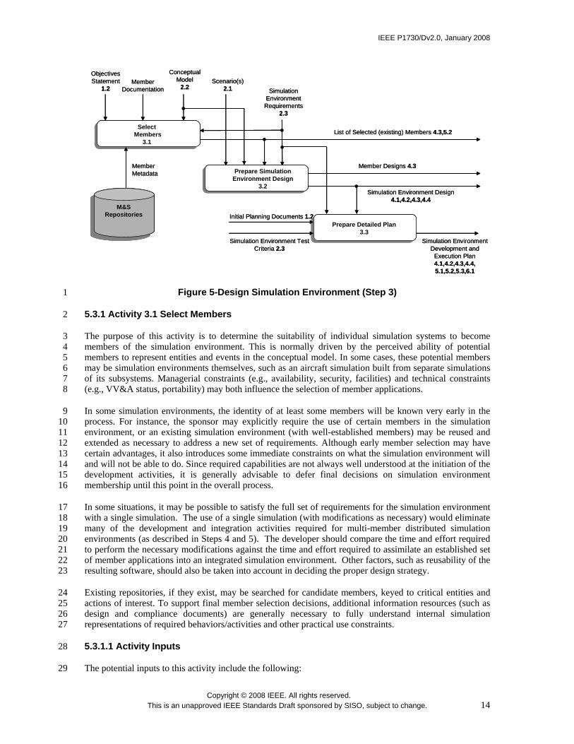
5.3 Step 3: Design Simulation Environment 25
The purpose of this step of the DSEEP is to produce the design of the simulation environment that will be 26 implemented in step 4. This involves identifying applications that will assume some defined role in the 27 simulation environment (members) that are suitable for reuse, creating new members if required, allocating 28 the required functionality to the members, and developing a detailed plan for the development and 29 implementation of the simulation environment. Figure 5 illustrates the key activities in this step of the 30 DSEEP. The subsections that follow describe each of these activities in detail. 31
IEEE P1730/Dv2.0, January 2008
Copyright © 2008 IEEE. All rights reserved. This is an unapproved IEEE Standards Draft sponsored by SISO, subject to change. 14
MemberMetadata
Initial Planning Documents 1.2
Member Documentation
Simulation Environment Design 4.1,4.2,4.3,4.4
SimulationEnvironment
Requirements 2.3
Simulation Environment Development and
Execution Plan 4.1,4.2,4.3,4.4,5.1,5.2,5.3,6.1
Simulation Environment Test Criteria 2.3
List of Selected (existing) Members 4.3,5.2
Member Designs 4.3
ObjectivesStatement
1.2Scenario(s)
2.1
SelectMembers
3.1
Prepare Simulation Environment Design
3.2
Prepare Detailed Plan3.3
Conceptual Model
2.2
M&S Repositories
M&S Repositories
Figure 5-Design Simulation Environment (Step 3) 1
5.3.1 Activity 3.1 Select Members 2
The purpose of this activity is to determine the suitability of individual simulation systems to become 3 members of the simulation environment. This is normally driven by the perceived ability of potential 4 members to represent entities and events in the conceptual model. In some cases, these potential members 5 may be simulation environments themselves, such as an aircraft simulation built from separate simulations 6 of its subsystems. Managerial constraints (e.g., availability, security, facilities) and technical constraints 7 (e.g., VV&A status, portability) may both influence the selection of member applications. 8
In some simulation environments, the identity of at least some members will be known very early in the 9 process. For instance, the sponsor may explicitly require the use of certain members in the simulation 10 environment, or an existing simulation environment (with well-established members) may be reused and 11 extended as necessary to address a new set of requirements. Although early member selection may have 12 certain advantages, it also introduces some immediate constraints on what the simulation environment will 13 and will not be able to do. Since required capabilities are not always well understood at the initiation of the 14 development activities, it is generally advisable to defer final decisions on simulation environment 15 membership until this point in the overall process. 16
In some situations, it may be possible to satisfy the full set of requirements for the simulation environment 17 with a single simulation. The use of a single simulation (with modifications as necessary) would eliminate 18 many of the development and integration activities required for multi-member distributed simulation 19 environments (as described in Steps 4 and 5). The developer should compare the time and effort required 20 to perform the necessary modifications against the time and effort required to assimilate an established set 21 of member applications into an integrated simulation environment. Other factors, such as reusability of the 22 resulting software, should also be taken into account in deciding the proper design strategy. 23
Existing repositories, if they exist, may be searched for candidate members, keyed to critical entities and 24 actions of interest. To support final member selection decisions, additional information resources (such as 25 design and compliance documents) are generally necessary to fully understand internal simulation 26 representations of required behaviors/activities and other practical use constraints. 27
5.3.1.1 Activity Inputs 28
The potential inputs to this activity include the following: 29

IEEE P1730/Dv2.0, January 2008
Copyright © 2008 IEEE. All rights reserved. This is an unapproved IEEE Standards Draft sponsored by SISO, subject to change. 15
1 — Objectives statement 2 — Conceptual model 3 — Simulation environment requirements 4 — Member documentation 5 6
5.3.1.2 Recommended Tasks 7
The potential tasks for this activity include the following: 8 9 — Define criteria for member selection 10 — Determine if an existing, reusable simulation environment meets or partially satisfies the identified 11
requirements 12 — Identify candidate members (including predefined members) 13 — Analyze the ability of each candidate member to represent required entities and events 14 — Review overall purpose and objectives with respect to selected members and availability of 15
resources 16 — Document rationale (including assumptions) for selection of members 17
5.3.1.3 Activity Outcomes 18
The potential outcomes for this activity include the following: 19 20 — List of selected (existing) members, including selection documentation such as criteria and rationale. 21
5.3.2 Activity 3.2 Prepare Simulation Environment Design 22
Once all members have been identified, the next major activity is to prepare the simulation environment 23 design and allocate the responsibility to represent the entities and actions in the conceptual model to the 24 members. This activity will allow for an assessment of whether the set of selected members provides the 25 full set of required functionality. A by-product of the allocation of functionality to the members will be 26 additional design information which can embellish the conceptual model. 27
As agreements on assigned responsibilities are negotiated, various design trade-off investigations may be 28 conducted as appropriate to support the development of the simulation environment design. Many of these 29 investigations can be considered to be early execution planning and may include technical issues such as 30 time management, execution management, infrastructure design, runtime performance, and potential 31 implementation approaches. In this latter case, this would include the selection of the underlying 32 simulation protocol or the selection of multiple protocols (including the identification of appropriate 33 bridging mechanisms in the infrastructure design). The major inputs to this activity include the simulation 34 environment requirements, the scenario, and the conceptual model (see Figure 5). In this activity, the 35 conceptual model is used as a conduit to ensure that user domain-specific requirements are appropriately 36 translated into the simulation environment design. High-level design strategies, including modeling 37 approaches and/or tool selection, may be revisited and renegotiated at this time based on inputs from the 38 members. When the simulation environment represents a modification or extension to a previous 39 simulation environment, new members must be made cognizant of all previously negotiated agreements 40 within that earlier simulation environment and given the opportunity to revisit pertinent technical issues. 41 For secure applications, efforts associated with maintaining a secure posture during the simulation 42 environment execution can begin, including the designation of security responsibility. The initial security 43 risk assessment and concept of operations may be refined at this time to clarify the security level and mode 44 of operation. 45
In the case that an existing set of members cannot fully address all defined requirements, it may be 46 necessary to perform an appropriate set of design activities at the member level. This may involve 47 enhancements to one or more of the selected members, or could even involve designing an entirely new 48

IEEE P1730/Dv2.0, January 2008
Copyright © 2008 IEEE. All rights reserved. This is an unapproved IEEE Standards Draft sponsored by SISO, subject to change. 16
member. The development team must balance long-term reuse potential versus time and resource 1 constraints in the evaluation of viable design options. 2
5.3.2.1 Activity Inputs 3
The potential inputs to this activity include the following: 4 5 — Conceptual model 6 — Scenario(s) 7 — Simulation environment requirements 8 — List of selected (existing) members 9
5.3.2.2 Recommended Tasks 10
The potential tasks for this activity include the following: 11 12 — Analyze selected members and identify those that best provide required functionality and fidelity 13 — Allocate functionality to selected members and determine if modifications are necessary and/or if 14
development of a new member(s) is needed 15 — Develop design for needed member modifications 16 — Develop design for new members (as necessary) 17 — Ensure that earlier decisions do not conflict with selected members 18 — Evaluate alternative design options, and identify the simulation environment design that best 19
addresses stated requirements 20 — Develop design for simulation environment infrastructure, and select protocol standards and 21
implementations 22 — Evaluate the need for bridging technologies 23 — Develop design of supporting databases 24 — Estimate simulation environment performance, and determine if actions are necessary to meet 25
performance requirements 26 — Analyze, and if necessary, refine initial security risk assessment and concept of operations 27 — Document the simulation environment design 28
5.3.2.3 Activity Outcomes 29
The potential outcomes for this activity include the following: 30 31 — Simulation environment design, including: 32
— Member responsibilities 33 — Simulation environment architecture (including supporting infrastructure design and 34
standards to be supported) 35 — Supporting tools (e.g. performance measurement equipment, network monitors) 36 — Implied requirements for member modifications and/or development of new members 37
— Member designs 38
5.3.3 Activity 3.3 Prepare Detailed Plan 39
Another major activity in step 3 (Simulation Environment Design) is to develop a coordinated plan to 40 guide the development, test, and execution of the simulation environment. This requires close collaboration 41 among all members to ensure a common understanding of the various goals and requirements and also to 42 identify (and agree to) appropriate methodologies and procedures based on recognized systems engineering 43 principles. The initial planning documents prepared during development of the original objectives provide 44 the basis for this activity (see Figure 5). The plan should include the specific tasks and milestones for each 45 member, along with proposed dates for completion of each task. 46

IEEE P1730/Dv2.0, January 2008
Copyright © 2008 IEEE. All rights reserved. This is an unapproved IEEE Standards Draft sponsored by SISO, subject to change. 17
The plan may also identify the software tools that will be used to support the remaining life cycle of the 1 simulation environment (e.g., CASE, configuration management, V&V, testing). For simulation 2 environments with stochastic properties, (e.g., Monte Carlo techniques), the plan may include an 3 experimental design. For new simulation environments, a plan to design and develop a network 4 configuration may be required. These agreements, along with a detailed work plan, must be documented 5 for later reference and possible reuse in future applications. 6
5.3.3.1 Activity Inputs 7
The potential inputs for this activity include the following: 8 9 — Initial planning documents 10 — Simulation environment requirements 11 — Simulation environment design 12 — Simulation environment test criteria 13 14
5.3.3.2 Recommended Tasks 15
The potential tasks for this activity include the following: 16 17 — Refine and augment the initial development and execution plan, including specific tasks and 18
milestones for each member 19 — Identify needed simulation environment agreements and plans for securing these agreements 20 — Develop approach and plan for integration of the simulation environment 21 — Revise VV&A and test plans (based on test criteria) 22 — Finalize plans for data collection, management, and analysis 23 — Complete selection of supporting tools, and develop plan for acquiring and installing the tools 24 — Develop plans and procedures for establishing and managing configuration baselines 25 — Translate simulation environment requirements into explicit execution and management plans 26 — If required, prepare design of experiments 27
5.3.3.3 Activity Outcomes 28
The potential outcomes for this activity include the following: 29 30 — Simulation environment development and execution plan, including: 31
— Schedule of activities, including detailed task and milestone identification 32 — Integration plan 33 — VV&A plan 34 — Test and evaluation plan 35 — Security plan 36 — Data management plan 37 — Configuration management plan 38 — Identification of required support tools 39
5.4 Step 4: Develop Simulation Environment 40
The purpose of this step of the DSEEP is to define the information that will be exchanged at runtime 41 during the execution of the simulation environment, modify member applications if necessary, and prepare 42 the simulation environment for integration and test (database development, security procedure 43 implementation, etc.). Figure 6 illustrates the key activities in this phase of the DSEEP. The subsections 44 that follow describe each of these activities in detail. 45

IEEE P1730/Dv2.0, January 2008
Copyright © 2008 IEEE. All rights reserved. This is an unapproved IEEE Standards Draft sponsored by SISO, subject to change. 18
Implement Simulation Environment
Infrastructure 4.4
Supporting Resources
Scenario(s) 2.1
Modified/new Members 5.2(New)Object Model
SimulationEnvironment Agreements
5.1,5.2,5.3,6.1
Data Dictionary Elements
Supporting Databases 5.2
List of Selected (existing) Members
3.1
ImplementedSimulation
EnvironmentInfrastructure 5.2
ExistingObjectModels
Develop Object Model
4.1
Establish Simulation Environment
Agreements 4.2
Implement Member Designs 4.3
Scenario Instance(s) 5.1
ObjectModel
LibrariesData
Dictionaries
Other Resources
Existing ObjectModels
MemberInterfaces
Simulation Environment
Design3.2
SimulationEnvironment Development
and Execution
Plan3.3
ObjectModel 5.1,5.2
SimulationEnvironment
Requirements 2.3
Conceptual Model
2.2
Member Designs
3.2
Implement Simulation Environment
Infrastructure 4.4
Supporting Resources
Scenario(s) 2.1
Modified/new Members 5.2(New)Object Model
SimulationEnvironment Agreements
5.1,5.2,5.3,6.1
Data Dictionary Elements
Supporting Databases 5.2
List of Selected (existing) Members
3.1
ImplementedSimulation
EnvironmentInfrastructure 5.2
ExistingObjectModels
Develop Object Model
4.1
Establish Simulation Environment
Agreements 4.2
Implement Member Designs 4.3
Implement Member Designs 4.3
Scenario Instance(s) 5.1
ObjectModel
Libraries
ObjectModel
LibrariesData
DictionariesData
Dictionaries
Other Resources
Other Resources
Existing ObjectModels
MemberInterfaces
Simulation Environment
Design3.2
SimulationEnvironment Development
and Execution
Plan3.3
ObjectModel 5.1,5.2
SimulationEnvironment
Requirements 2.3
Conceptual Model
2.2
Member Designs
3.2
Figure 6-Develop Simulation Environment (Step 4) 1
5.4.1 Activity 4.1 Develop Information Exchange Data Model 2
In order for the simulation environment to operate properly, there must be some means for member 3 applications to interact. At a minimum, this implies the need for runtime data exchange, along it could also 4 involve remote method invocations or other such means of direct interaction among cooperating object 5 representations. Clearly, there must be agreements among the members as to the how these interactions 6 will take place, defined in terms of software artifacts like class relationships and data structures. 7 Collectively, the set of agreements that govern how this interaction takes place is referred to as the 8 information exchange data model. 9
Depending on the nature of the application, the information exchange data model may take several forms. 10 Some distributed applications are strictly object-oriented, where both static and dynamic views of the 11 simulation system are defined in terms of class structures, class attributes, and class operations (i.e., 12 methods) within the information exchange data model. Other distributed applications maintain this same 13 object-based paradigm, but use object representations as a way to share state information among different 14 members about entities and events that are being modeled internal to the members themselves. In this case, 15 the information exchange data model is quite similar to a data model, including a defined set of format, 16 syntax, and encoding rules. Still other distributed applications may not use an object-based structure at all 17 in their information exchange data model, but rather focuses on the runtime data structures themselves and 18 the conditions that cause the information to be exchanged. In general, different applications will have 19 different requirements for the depth and nature of interaction among members, and while these varying 20 requirements will drive the type and content of the information exchange data model, it is necessary for the 21 information exchange data model to exist in order to formalize the "contract" among members necessary to 22 achieve coordinated and coherent interoperation within the simulation environment. 23
There are many possible approaches to information exchange data model development. Certainly, reuse of 24 an existing information exchange data model is the most expeditious approach, if one can be found that 25 meets all member interaction requirements. If an exact match for the needs of the current application 26 cannot be found, then identifying an information exchange data model that meets some of these needs and 27 modifying/tailoring the information exchange data model to meet the full set of requirements would 28 generally be preferable than starting from a "clean sheet". Some communities maintain reference 29 information exchange data models for their users to facilitate this type of reuse (e.g., the Real-time 30 Platform Reference Federation Object Model [RPR FOM]). Still other approaches involve assembling an 31 information exchange data model from small, reusable information exchange data model components (e.g., 32 Base Object Models [BOM], [B4]) and merging information exchange data model elements from the 33
IEEE P1730/Dv2.0, January 2008
Copyright © 2008 IEEE. All rights reserved. This is an unapproved IEEE Standards Draft sponsored by SISO, subject to change. 19
interfaces of member applications (e.g., HLA Simulation Object Models [SOM]). In general, the 1 simulation environment development team should employ whatever approach makes most sense from a 2 cost, efficiency, and quality perspective. 3
5.4.1.1 Activity Inputs 4
The potential inputs to this activity include the following: 5 6 — Simulation environment design 7 — Member interfaces 8 — Simulation environment development and execution plan 9 — Data dictionaries 10 — Existing information exchange data models 11 — Supporting resources (e.g., information exchange data model development tools, information 12
exchange data model libraries, dictionaries) 13 — Conceptual model 14
5.4.1.2 Recommended Tasks 15
The potential tasks for this activity include the following: 16 17 — Choose an information exchange data model development approach. 18 — Identify appropriate information exchange data models or information exchange data model subsets 19
for reuse. 20 — Review applicable data dictionaries to identify relevant information exchange data model elements. 21 — Develop and document the information exchange data model using an appropriate tool. 22 — Verify that the information exchange data model conforms to the conceptual model. 23
5.4.1.3 Activity Outcomes 24
The potential outcomes for this activity include the following: 25 26 — Information Exchange Data Model 27
5.4.2 Activity 4.2 Establish Simulation Environment Agreements 28
Although the information exchange data model represents an agreement among members as the how 29 runtime interaction will take place, there are other operating agreements that must be reached among 30 developers and management (prior to implementation) that are not documented in the information 31 exchange data model. Such agreements are necessary to establish a fully consistent, interoperable, 32 distributed simulation environment. While the actual process of establishing agreements among all 33 participants in the development effort begins early in the DSEEP and is embodied in each of its activities, 34 this may not result in a complete set of formally documented agreements. It is at this point in the overall 35 process that developers need to explicitly consider what additional agreements are required and how they 36 should be documented. 37
There are many different types of such agreements. For instance, members must use the conceptual model 38 to gain an understanding and agreement on the behavior of all objects within the simulation environment. 39 While behaviors that involve multiple objects will be documented to some extent in the information 40 exchange data model, other means may be required to fully address these issues. Additional requirements 41 for software modifications to selected members may be identified as a result of these discussions; such 42 requirements must be addressed prior to integration activities. Also, agreements must be reached as to the 43 databases and algorithms that must be common (or at least consistent) across the simulation environment to 44 guarantee valid interactions among all members. For instance, a consistent view of the features and 45 phenomena represented across the entire simulated environment is critical in order for objects owned by 46 different members to interact and behave in a realistic fashion. In addition, certain operational issues must 47
IEEE P1730/Dv2.0, January 2008
Copyright © 2008 IEEE. All rights reserved. This is an unapproved IEEE Standards Draft sponsored by SISO, subject to change. 20
be addressed and resolved among all members. For instance, agreements on initialization procedures, 1 synchronization points, save/restore policies, and security procedures are all necessary to ensure proper 2 operation of the simulation environment. 3
Once all authoritative data sources that will be used in support of the simulation environment have been 4 identified, the actual data stores are used to transition the functional description of the scenario (developed 5 in Step 2; see Figure 4) to an executable scenario instance (or set of instances). The product of this activity 6 permits testing to be conducted directly within the context of the domain of interest and also drives the 7 execution of the simulation environment later in the DSEEP. 8
Finally, developers must recognize that certain agreements may require the activation of other processes 9 external to the DSEEP. For instance, utilization and /or modification of certain members may require 10 contractual actions between the user/sponsor and the developer. Even where contractual actions may not be 11 required, formal memoranda of agreement may be required between members. Additionally, simulation 12 environments requiring the processing of classified data will generally require the establishment of a 13 security agreement between the appropriate security authorities. Each of these external processes has the 14 potential to negatively impact the development and execution of a simulation environment within resource 15 and schedule constraints and should be factored into project plans as early as possible. 16
5.4.2.1 Activity Inputs 17
The potential inputs to this activity include the following: 18 19 — Scenario(s) 20 — Conceptual model 21 — Simulation environment design 22 — Simulation environment development and execution plan 23 — Simulation environment requirements 24 — Information exchange data model 25
5.4.2.2 Recommended Tasks 26
The potential tasks for this activity include the following: 27 28 — Decide the behavior of all objects within the simulation environment 29 — Identify the necessary software modifications to selected members, not previously identified 30 — Decide which databases and algorithms must be common or consistent 31 — Identify authoritative data sources for both member and simulation environment databases 32 — Build all required databases 33 — Decide how time should be managed in the simulation environment 34 — Establish synchronization points for the simulation environment and the procedures for initialization 35 — Decide strategy for how the simulation environment shall be saved and restored 36 — Decide how data is to be distributed across the simulation environment 37 — Transform the functional scenario description to an executable scenario (scenario instance[s]) 38 — Review security agreements, and establish security procedures 39
5.4.2.3 Activity Outcomes 40
The potential outcomes for this activity include the following: 41 42 — Simulation environment agreements, including: 43
— Established security procedures 44 — Time management agreements 45 — Data management and distribution agreements 46 — Defined synchronization points and initialization procedures 47 — Save/restore strategy 48

IEEE P1730/Dv2.0, January 2008
Copyright © 2008 IEEE. All rights reserved. This is an unapproved IEEE Standards Draft sponsored by SISO, subject to change. 21
— Agreements on supporting databases and algorithms 1 — Agreements on authoritative data sources 2 — Agreements on publication and subscription responsibilities 3
— Scenario instance(s) 4
5.4.3 Activity 4.3 Implement Member Designs 5
The purpose of this activity is to implement whatever modifications are necessary to the members to ensure 6 that they can represent assigned objects and associated behaviors as described in the conceptual model 7 (step 2), produce and exchange data with other members as defined by the information exchange data 8 model, and abide by the established simulation environment agreements. This may require internal 9 modifications to the member to support assigned domain elements, or it may require modifications or 10 extensions to the member’s external interface to support new data structures or services that were not 11 supported in the past. In some cases, it may even be necessary to develop a whole new interface for the 12 member, depending on the content of the information exchange data model and simulation environment 13 agreements. In this situation, the member must consider both the resource (e.g., time, cost) constraints of 14 the immediate application as well as longer-term reuse issues in deciding the best overall strategy for 15 completing the interface. In situations where entirely new members are needed, the implementation of the 16 member design must take place at this time. 17
5.4.3.1 Activity Inputs 18
The potential inputs to this activity include the following: 19 20 — Simulation environment development and execution plan 21 — List of selected (existing) members 22 — Member designs 23 — Simulation environment design 24 — Simulation environment agreements 25 — Scenario instance(s) 26
5.4.3.2 Recommended Tasks 27
The potential tasks for this activity include the following: 28 29 — Implement member modifications to support allocated functionality 30 — Implement modifications of, or extensions to, the interfaces of all members 31 — Develop a new interface for those members for which it is required 32 — Implement design of new members as required 33 — Implement design of supporting databases and scenario instance(s) 34
5.4.3.3 Activity Outcomes 35
The potential outcomes for this activity include the following: 36 37 — Modified and/or new members 38 — Supporting databases 39
5.4.4 Activity 4.4 Implement Simulation Environment Infrastructure 40
The purpose of this activity is to implement, configure, and initialize the infrastructure necessary to support 41 the simulation environment and verify that it can support the execution and intercommunication of all 42 members. This involves the implementation of the network design, e.g., WANs, LANs; the initialization 43 and configuration of the network elements, e.g., routers, bridges; and the installation and configuration of 44 supporting software on all computer systems. This also involves whatever facility preparation is necessary 45 to support integration and test activities. 46

IEEE P1730/Dv2.0, January 2008
Copyright © 2008 IEEE. All rights reserved. This is an unapproved IEEE Standards Draft sponsored by SISO, subject to change. 22
5.4.4.1 Activity Inputs 1
The potential inputs to this activity include the following: 2 3 — Simulation environment design 4 — Simulation environment development and execution plan 5
5.4.4.2 Recommended Tasks 6
The potential tasks for this activity include the following: 7 8 — Prepare integration/test facility, including: 9
— Ensure basic facility services (air conditioning, electric power, etc.) are functional and 10 available. 11
— Ensure availability of required hardware/software in integration/test facility. 12 — Perform required system administration functions (establish user accounts, establish 13
procedures for file backups, etc.). 14 — Implement infrastructure design, including: 15
— Install and configure required hardware elements. 16 — Install and configure RTI and other supporting software. 17 — Test infrastructure to ensure proper operation. 18
5.4.4.3 Activity Outcomes 19
The potential outcomes for this activity include the following: 20 21 — Implemented simulation environment infrastructure 22
5.5 Step 5: Plan, Integrate, and Test Simulation Environment 23
The purpose of this step of the DSEEP is to plan the execution of the simulation environment, establish all 24 required interconnectivity between members, and test the simulation environment prior to execution. 25 Figure 7 illustrates the key activities in this step of the DSEEP. The subsections that follow describe each 26 of these activities. 27
5.5.1 Activity 5.1 Plan Execution 28
The main purpose of this activity is to fully describe the execution environment and develop an execution 29 plan. For instance, performance requirements for individual members and for the larger simulation 30 environment along with salient characteristics of host computers, operating systems, and networks that will 31 be used in the simulation environment should all be documented at this time. The completed set of 32 information, taken together with the information exchange data model and simulation environment 33 agreements, provides the necessary foundation to transition into the integration and testing phase of 34 development. 35

IEEE P1730/Dv2.0, January 2008
Copyright © 2008 IEEE. All rights reserved. This is an unapproved IEEE Standards Draft sponsored by SISO, subject to change. 23
Integrate Simulation Environment
5.2
Tested SimulationEnvironment 6.1
Execution Environment Description 6.1
List of Selected(existing)
Members 3.1Modified/new Members 4.3
Simulation Environment Test Criteria
2.3
Supporting Databases
4.3
Implemented Simulation
Environment Infrastructure
4.4
ObjectModel
4.1
SimulationEnvironment Agreements
4.2
Scenario Instance(s)
4.2
Test Simulation Environment
5.3
Plan Execution
5.1
Integrated Simulation
Environment
SimulationEnvironment Development
and Execution
Plan3.3
Figure 7-Plan, Integrate, and Test Simulation Environment (Step 5) 1
Additional activities in this step include the incorporation of any necessary refinements to test and VV&A 2 plans and (for secure environments) the development of a security test and evaluation plan. This latter 3 activity requires reviewing and verifying the security work accomplished thus far in the simulation 4 environment development and finalizing the technical details of security design, such as information 5 downgrading rules, formalized practices, etc. This plan represents an important element of the necessary 6 documentation set for the simulation environment. 7
Operational planning is also a key aspect of this activity. This planning should address who will be 8 involved in each execution run, both in a support and operational role. It should detail the schedule for both 9 the execution runs and the necessary preparation prior to each run. Training and rehearsal for support and 10 operational personnel should be addressed as necessary. Specific procedures for starting, conducting, and 11 terminating each execution run should be documented. 12
5.5.1.1 Activity Inputs 13
The potential inputs to this activity include the following: 14 15 — Information Exchange Data Model 16 — Scenario Instance(s) 17 — Simulation environment agreements 18 — Simulation environment development and execution plan 19
5.5.1.2 Recommended Tasks 20
The potential tasks for this activity include the following: 21 22 — Refine/augment simulation environment development and execution plan in the areas of VV&A, 23
test, and security, as necessary 24 — Assign members to appropriate infrastructure elements 25 — Identify risks, and take action to reduce risks 26 — Document all information relevant to the execution 27

IEEE P1730/Dv2.0, January 2008
Copyright © 2008 IEEE. All rights reserved. This is an unapproved IEEE Standards Draft sponsored by SISO, subject to change. 24
— Develop detailed execution plans 1
5.5.1.3 Activity Outcomes 2
The potential outcomes for this activity include the following: 3 4 — Execution Environment Description 5 — Revised simulation environment development and execution plan (as necessary) 6
5.5.2 Activity 5.2 Integrate Simulation Environment 7
The purpose of this activity is to bring all of the members into a unifying operating environment. This 8 requires that all hardware and software assets are properly installed and interconnected in a configuration 9 that can support the information exchange data model and simulation environment agreements. Because 10 WAN/LAN problems are often difficult to diagnose and correct, the WAN/LAN connection should be 11 established as a first step, especially when dealing with secure connections. The simulation environment 12 development and execution plan specifies the integration methodology used in this activity, and the 13 scenario instance provides the necessary context for integration activities. 14
Integration activities are normally performed in close coordination with testing activities. Iterative “test-15 fix-test” approaches are used quite extensively in practical applications and have been shown to be quite 16 effective. 17
5.5.2.1 Activity Inputs 18
The potential inputs to this activity include the following: 19 20 — Simulation environment development and execution plan 21 — Execution environment description 22 — Simulation environment agreements 23 — Information Exchange Data Model 24 — Members (existing selected, modified and/or newly developed members) 25 — Implemented simulation environment infrastructure 26 — Supporting databases 27 28
5.5.2.2 Recommended Tasks 29
The potential tasks for this activity include the following: 30 31 — Ensure that all member software is properly installed and interconnected 32 — Establish method for managing known software problems and "workarounds" 33 — Perform incremental integration according to plan 34
5.5.2.3 Activity Outcomes 35
The potential outcomes for this activity include the following: 36 37 — Integrated simulation environment 38
5.5.3 Activity 5.3 Test Simulation Environment 39
The purpose of this activity is to test that all of the members can interoperate to the degree required to 40 achieve core objectives. Three levels of testing are defined for distributed applications: 41

IEEE P1730/Dv2.0, January 2008
Copyright © 2008 IEEE. All rights reserved. This is an unapproved IEEE Standards Draft sponsored by SISO, subject to change. 25
Member Testing: In this activity, each member is tested to ensure that the member software correctly 1 implements its role in the simulation environment as documented in the information exchange data model, 2 execution environment description, and any other operating agreements. 3
Integration Testing: In this activity, the simulation environment is tested as an integrated whole to verify a 4 basic level of interoperability. This testing primarily includes observing the ability of the members to 5 interact correctly with the supporting infrastructure and to communicate with other members as described 6 by the information exchange data model. 7
Interoperability Testing: In this activity, the ability of the simulation environment to interoperate to the 8 degree necessary to achieve identified objectives is tested. This includes observing the ability of members 9 to interact according to the defined scenario and to the level of fidelity required for the application. This 10 activity also includes security certification testing if required for the application. The results from 11 interoperability testing may contribute to verification and validation of the simulation environment as 12 required. 13
Procedures for conducting interoperability testing must be agreed upon by all members and documented 14 appropriately. Data collection plans should be exercised during the testing phase to ensure that the data 15 needed to support the overall objectives is being accurately collected and stored. 16
The desired output from this activity is an integrated, tested, validated, and if required, accredited 17 simulation environment that indicates that execution of the simulation environment can commence. If early 18 testing and validation uncover obstacles to successful integration and accreditation, the developers must 19 take corrective actions. In many cases, these corrective actions simply require a relatively minor software 20 fix (or series of fixes) or minor adjustment to the information exchange data model. However, testing may 21 also uncover more serious software, interoperability, or validity problems. In these cases, options may need 22 to be identified, with their associated cost and schedule estimates (including security and VV&A 23 implications), and should be discussed with the user/sponsor of the simulation environment before 24 corrective action is taken. 25
5.5.3.1 Activity Inputs 26
The potential inputs to this activity include the following: 27 28 — Simulation environment development and execution plan 29 — Simulation environment agreements 30 — Execution environment description 31 — Integrated Simulation environment 32 — Simulation environment test criteria 33
5.5.3.2 Recommended Tasks 34
The potential tasks for this activity include the following: 35 36 — Perform member-level testing 37 — Perform connectivity and interoperability testing across the full simulation environment 38 — Analyze testing results (i.e., compare against test criteria) 39 — Review test results with user/sponsor 40
5.5.3.3 Activity Outcomes 41
The potential outcomes for this activity include the following: 42 43 — Tested (and if necessary, accredited) simulation environment, including 44
— Member test data 45 — Tested members 46

IEEE P1730/Dv2.0, January 2008
Copyright © 2008 IEEE. All rights reserved. This is an unapproved IEEE Standards Draft sponsored by SISO, subject to change. 26
— Simulation environment test data 1 — Corrective actions 2
5.6 Step 6: Execute Simulation Environment and Prepare Outputs 3
The purpose of this step of the DSEEP is to execute the simulation environment and to pre-process the 4 resulting output data. Figure 8 illustrates the key activities in this step of the DSEEP. The subsections that 5 follow describe each of these activities. 6
Raw Execution Outputs Derived Outputs 7.1
Tested Simulation
Environment5.3
Simulation Environment Agreements
4.2
Execution Environment Description
5.1
Documented Execution Problems
Execute Simulation Environment6.1
Prepare Simulation Environment Outputs
6.2
Simulation Environment Development
and Execution
Plan3.3
Raw Execution Outputs Derived Outputs 7.1
Tested Simulation
Environment5.3
Simulation Environment Agreements
4.2
Execution Environment Description
5.1
Documented Execution Problems
Execute Simulation Environment6.1
Execute Simulation Environment6.1
Prepare Simulation Environment Outputs
6.2
Simulation Environment Development
and Execution
Plan3.3
Simulation Environment Development
and Execution
Plan3.3
Figure 8-Execute Simulation Environment and Prepare Outputs (Step 6) 7
5.6.1 Activity 6.1 Execute Simulation Environment 8
The purpose of this activity is to exercise all members of the simulation environment in a coordinated 9 fashion over time to generate required outputs, and thus achieve stated objectives. The simulation 10 environment must have been tested successfully before this activity can begin. 11
Execution management and data collection are critical to a successful simulation environment execution. 12 Execution management involves controlling and monitoring the execution via specialized software tools 13 (as appropriate). Execution can be monitored at the hardware level (e.g., CPU usage, network load), and/or 14 software operations can be monitored for individual members or across the full simulation environment. 15 During execution, key test criteria should be monitored to provide an immediate evaluation of the 16 successful execution of the simulation environment. 17
Data collection is focused on assembling the desired set of outputs and on collecting whatever additional 18 supporting data is required to assess the validity of the execution. In some cases, data is also collected to 19 support replays of the execution (i.e., “playbacks”). Essential runtime data may be collected via databases 20 in the members themselves, or can be collected via specialized data collection tools directly interfaced to 21 the simulation environment infrastructure. The particular strategy for data collection in any particular 22 simulation environment is entirely at the discretion of the development team, and should have been 23 documented in the Simulation Environment Requirements, the Simulation Environment Development and 24 Execution Plan, and in the Simulation Environment Agreements. 25
When security restrictions apply, strict attention must be given to maintaining the security posture of the 26 simulation environment during execution. A clear concept of operations, properly trained security 27 personnel, and strict configuration management will all facilitate this process. It is important to remember 28 that authorization to operate (accreditation) is usually granted for a specific configuration of members. Any 29 change to the members or composition of the M&S environment will certainly require a security review 30 and may require some or all of the security certification tests to be redone. 31

IEEE P1730/Dv2.0, January 2008
Copyright © 2008 IEEE. All rights reserved. This is an unapproved IEEE Standards Draft sponsored by SISO, subject to change. 27
5.6.1.1 Activity Inputs 1
The potential inputs to this activity include the following: 2 3 — Tested M&S environment 4 — M&S environment development and execution plan 5 — M&S environment agreements 6 — Execution environment description 7
5.6.1.2 Recommended Tasks 8
The potential tasks for this activity include the following: 9 10 — Perform identified executions and collect data. 11 — Manage the execution in accordance with the M&S environment development and execution plan. 12 — Document detected problems during execution. 13 — Ensure continued secure operation in accordance with certification and accreditation decisions and 14
requirements. 15
5.6.1.3 Activity Outcomes 16
The potential outcomes for this activity include the following: 17 18 — Raw execution outputs (data) 19 — Documented execution problems 20
5.6.2 Activity 6.2 Prepare M&S Environment Outputs 21
The purpose of this activity is to pre-process the output collected during the execution prior to the formal 22 analysis of the data in step 7. This may involve the use of data reduction techniques to reduce the quantity 23 of data to be analyzed and to transform the data to a particular format. Where data has been acquired from 24 many sources, data fusion techniques may have to be employed. The data should be reviewed and 25 appropriate action taken where missing or erroneous data is suspected. This may require further executions 26 to be conducted. 27
5.6.2.1 Activity Inputs 28
The potential inputs to this activity include the following: 29 30 — Raw execution outputs (data) 31 — Documented execution problems 32
5.6.2.2 Recommended Tasks 33
The potential tasks for this activity include the following: 34 35 — Merge data from multiple sources. 36 — Reduce/transform raw data. 37 — Review data for completeness and possible errors. 38
5.6.2.3 Activity Outcomes 39
The potential outcomes for this activity include the following: 40 41 — Derived outputs 42

IEEE P1730/Dv2.0, January 2008
Copyright © 2008 IEEE. All rights reserved. This is an unapproved IEEE Standards Draft sponsored by SISO, subject to change. 28
5.7 Step 7: Analyze Data and Evaluate Results 1
The purpose of this step of the DSEEP is to analyze and evaluate the data acquired during the execution of 2 the M&S environment (step 6), and to report the results back to the user/sponsor. This evaluation is 3 necessary to ensure that the M&S environment fully satisfies the requirements of the user/sponsor. The 4 results are fed back to the user/sponsor so that they can decide if the original objectives have been met, or 5 if further work is required. In the latter case, it will be necessary to repeat some of the DSEEP steps again 6 with modifications to the appropriate products. 7
Figure 9 illustrates the key activities in this step of the DSEEP. The subsections that follow describe each 8 of these activities. 9
Objectives Statement
1.2
Derived Outputs
6.2
Analyzed Data
SimulationEnvironment Test Criteria
2.3
Simulation Environment
Requirements 2.3
Reusable Products
Evaluate and Feedback Results
7.2
Lessons LearnedFinal ReportAnalyze Data
7.1
Objectives Statement
1.2
Derived Outputs
6.2
Analyzed Data
SimulationEnvironment Test Criteria
2.3
Simulation Environment
Requirements 2.3
Reusable Products
Evaluate and Feedback Results
7.2
Evaluate and Feedback Results
7.2
Lessons LearnedFinal ReportAnalyze Data
7.1Analyze Data
7.1 10
Figure 9-Analyze Data and Evaluate Results (Step 7) 11
5.7.1 Activity 7.1 Analyze Data 12
The main purpose of this activity is to analyze the execution data from step 6. This data may be supplied 13 using a range of different media (e.g., digital, video, audio), and appropriate tools and methods will be 14 required for analyzing the data. These may be commercial or government off-the-shelf (COTS/GOTS) 15 tools or specialized tools developed for a specific M&S environment. The analysis methods used will be 16 specific to a particular M&S environment and can vary between simple observations (e.g., determining 17 how many targets have been hit) to the use of complex algorithms (e.g., regression analysis or data 18 mining). In addition to data analysis tasks, this activity also includes defining appropriate "pass/fail" 19 evaluation criteria for the execution and defining appropriate formats for presenting results to the 20 user/sponsor. 21
5.7.1.1 Activity Inputs 22
The potential inputs to this activity include the following: 23 24 — Derived outputs 25 — Objectives statement 26
5.7.1.2 Recommended Tasks 27
The potential tasks for this activity include the following: 28 29 — Apply analysis methods and tools to data. 30 — Define appropriate presentation formats. 31 — Prepare data in chosen formats. 32
5.7.1.3 Activity Outcomes 33
The potential outcomes for this activity include the following: 34 35 — Analyzed data 36

IEEE P1730/Dv2.0, January 2008
Copyright © 2008 IEEE. All rights reserved. This is an unapproved IEEE Standards Draft sponsored by SISO, subject to change. 29
5.7.2 Activity 7.2 Evaluate and Feedback Results 1
There are two main evaluation tasks. In the first task, the derived results from the previous activity are 2 evaluated to determine if all objectives have been met. This requires a retracing of execution results to the 3 measurable set of requirements originally generated during conceptual analysis (step 2) and refined in 4 subsequent steps. This step also includes evaluating the results against the test criteria for the M&S 5 environment. In the vast majority of cases, any impediments to fully satisfying the requirements have 6 already been identified and resolved during the earlier development and integration phases. Thus, for well-7 designed M&S environments, this task is merely a final check. In those rare cases in which certain 8 objectives have not been fully met at this late stage of the overall process, corrective actions must be 9 identified and implemented. This may necessitate revisiting previous steps of the DSEEP and regenerating 10 results. 11
The second evaluation task in this activity, assuming all objectives have been achieved, is to store all 12 reusable products in an appropriate archive for general reuse within the domain or broader user 13 community. Examples of potentially reusable products include the scenario and the conceptual model, 14 although there may be several others. In fact, it may be advantageous in some instances to capture the full 15 set of products required to reproduce the execution of the M&S environment. Determination of which 16 products have potential for reuse in future applications is at the discretion of the development team. 17
5.7.2.1 Activity Inputs 18
The potential inputs to this activity include the following: 19 20 — Analyzed data 21 — Objectives statement 22 — M&S environment requirements 23 — M&S environment test criteria 24
5.7.2.2 Recommended Tasks 25
The potential tasks for this activity include the following: 26 27 — Determine if all objectives for the M&S environment have been met. 28 — Take appropriate corrective actions if deficiencies are found. 29 — Archive all reusable products. 30
5.7.2.3 Activity Outcomes 31
The potential outcomes for this activity include the following: 32 33 — Lessons learned 34 — Final report 35 — Reusable products 36
6. Conclusion 37
This document has provided a view of the DSEEP. Currently, this model represents the best practices 38 available to the distributed simulation user community. The DSEEP is an easily tailored process and is 39 offered as guidance to all users, developers, and managers of distributed simulation environments. As 40 additional experience is accrued in building such applications, the DSEEP will leverage this knowledge 41 and evolve accordingly. 42
The DSEEP has been designed to serve as the generalized framework from which alternative; more 43 detailed views can be specified in order to better serve the specialized needs of specific communities. Such 44
IEEE P1730/Dv2.0, January 2008
Copyright © 2008 IEEE. All rights reserved. This is an unapproved IEEE Standards Draft sponsored by SISO, subject to change. 30
views provide more detailed “hands-on” guidance to users of this process from the perspective of a 1 particular domain (e.g., analysis, training), a particular discipline (e.g., VV&A, security), or a particular 2 implementation strategy (e.g., HLA, DIS, TENA). Some selected examples of this latter case are provided 3 as annexes to this document. In general, participants in distributed simulation activities are encouraged to 4 perform these types of adaptations whenever appropriate. 5
7. Bibliography 6
[B1] A Glossary of Modeling and Simulation Terms for Distributed Interactive Simulation (DIS), August 7 1995. 8
[B2] IEEE Std 100-1996, The IEEE Standard Dictionary of Electrical and Electronics Terms, 6th Edition, 9 1996. 10
[B3] Scrudder R., Waite W., Richardson M., and Lutz R., Graphical Presentation of the Federation 11 Development and Execution Process, Simulation Interoperability Workshop, Fall 1998. 12
[B4] Gustavson, P., et al. “Base Object Model (BOM) Template Specification” SISO-STD-003-2006, May 13 2006. 14

IEEE P1730/Dv2.0, January 2008
Copyright © 2008 IEEE. All rights reserved. This is an unapproved IEEE Standards Draft sponsored by SISO, subject to change. 31
Annex A: High Level Architecture (HLA) Process Overlay to the DSEEP 1
Introduction 2
The High Level Architecture is a technical architecture developed to facilitate the reuse and interoperation 3 of simulation systems and assets (e.g. federation managers, data collectors, passive viewers, real world 4 ("live") systems, and other utilities). It was developed in response to the clear recognition of the value of 5 modeling and simulation in supporting a wide variety of applications, as well as the need to manage M&S 6 assets as cost effective tools. It is intended as a general-purpose architecture, in that a very wide range of 7 standardized services and capabilities are provided that collectively meets the needs of a very broad 8 spectrum of potential users. For instance, HLA provides time management services for those distributed 9 applications that require either faster or slower than real-time operation, advanced filtering capabilities for 10 very large-scale applications (with scalability concerns), and services to manage the operation of the 11 distributed simulation environment. While most applications only employ a defined subset of the full 12 range of HLA services, it is believed that the union of all HLA services is sufficient to address the needs of 13 any class of user within the larger distributed simulation community. 14
A complete description of the HLA is provided in two different sources. The U.S. Department of Defense 15 (DoD) sponsored the original development of the HLA, which produced a series of stepwise revisions 16 culminating with the HLA v1.3 specifications including the Interface Specification, the Object Model 17 Template (OMT) Specification, and the Rules. These specifications are still in active use within various 18 U.S. DoD user communities today. Later, an effort to develop an industry standard for the HLA was 19 initiated in collaboration with the IEEE, resulting in the current IEEE 1516 series of HLA documents 20 (IEEE 1516, 1516.1, 1516.2). Both the HLA v1.3 and IEEE 1516 specifications are presently available to 21 users (see References), as are commercial and government tools/utilities to facilitate the development of 22 HLA applications. 23
Section 1: Terminology Mappings and Definitions (Specific Architecture / 24 Methodology to DSEEP) 25
Terminology Mappings: 26
Simulation Environment: Federation 27 Member: Federate 28 Information Exchange Data Model: Federation Object Model (FOM) or 29
Simulation Object Model (SOM) 30
Definitions: 31
Federation: A named set of federate applications and a common Federation Object Model that are used as 32 a whole to achieve some specific objective. 33
Federate: A member of a federation; a single application that may be or is currently coupled with other 34 software applications under a Federation Execution Data (FED) or Federation Object Model Document 35 Data (FDD) and a runtime infrastructure (RTI). 36
Federation Object Model: A specification defining the information exchanged at runtime to achieve a 37 given set of federation objectives. This includes object classes, object class attributes, interaction classes, 38 interaction parameters, and other relevant information. 39

IEEE P1730/Dv2.0, January 2008
Copyright © 2008 IEEE. All rights reserved. This is an unapproved IEEE Standards Draft sponsored by SISO, subject to change. 32
Simulation Object Model: A specification of the types of information that an individual federate could 1 provide to HLA federations as well as the information that an individual federate can receive from other 2 federates in HLA federations. 3
Section 2: Global Mapping (Specific Architecture/Methodology to DSEEP) 4
With appropriate term translations, the specific process used for developing and executing an HLA 5 federation1 is essentially the same as the DSEEP. That is, the HLA development process has the exact 6 same number of steps (seven), and each step can be decomposed down into the same basic set of activities. 7 Besides the obvious differences in terminology, the main differences are with respect to how the generic 8 activities and lower-level tasks described in the DSEEP are implemented in an HLA context. The 9 following sections identify the major steps and activities required to build and execute an HLA federation, 10 including a summary of the differences with the more generic DSEEP activity descriptions. 11
Section 3: Detailed Mappings (Specific Architecture/Methodology to DSEEP) 12
Step 1: Define Federation Objectives 13
Activity 1.1 Identify User/Sponsor Needs 14
This activity is identical to that described in the DSEEP. 15
Activity 1.2 Develop Federation Objectives 16
This activity is essentially identical to that described in the DSEEP. However, the Federation Objectives 17 Statement may contain information unique to HLA applications, such as rationale for the selection of HLA 18 as the preferred architecture/methodology and possible sponsor recommendations and/or constraints on the 19 choice of Runtime Infrastructure (RTI) and other HLA tools. 20
Step 2: Perform Conceptual Analysis 21
Activity 2.1 Develop Federation Scenario 22
Since the scenario description is independent of the simulation protocol, this activity is identical with the 23 DSEEP. 24
Activity 2.2 Develop Federation Conceptual Model 25
Like the scenario description, the Federation Conceptual Model is also independent of the simulation 26 protocol, and thus this activity is also identical with the DSEEP. 27
Activity 2.3 Develop Federation Requirements 28
While the necessary tasks to produce a set of testable requirements are essentially the same as other 29 architectures and methodologies, there may be some types of requirements that are unique to HLA. For 30 instance, requirements for runtime services in such areas as time management and data distribution 31 management may require the use of HLA, and in fact may be the primary rationale for the selection of 32 HLA as the supporting architecture. 33
1 Formally known as the HLA Federation Development and Execution Process (FEDEP).

IEEE P1730/Dv2.0, January 2008
Copyright © 2008 IEEE. All rights reserved. This is an unapproved IEEE Standards Draft sponsored by SISO, subject to change. 33
Step 3: Design Federation 1
Activity 3.1 Select Federates 2
The basic activity to select the participants in the federation is essentially the same as the DSEEP. 3 However, while the DSEEP identifies a generic set of M&S Repositories as the principal source of 4 candidate participants, the HLA development process identifies existing HLA object model libraries as the 5 primary means of federate selection. That is, existing Federation Object Models (FOM) are used to 6 identify federates that have previously participated in similar distributed applications, while existing 7 Simulation Object Models (SOM) are used to evaluate the ability of individual federates to support key 8 entities and interactions in current federation applications. While other sources can also be used to identify 9 candidate federates, existing FOM/SOM libraries are considered the main source. 10
There are also a number of HLA-specific factors that may affect federate selection. For instance, if time 11 management services will be used in the federation, the ability of potential federates to support HLA time 12 management services will be an important consideration. In general, the ability of a potential federate to 13 support required federation services will be a critical factor in selecting that federate for the current 14 federation application. 15
Activity 3.2 Prepare Federation Design 16
While the need to prepare the design of the simulation environment is obviously necessary for any 17 architecture/methodology, the decision to employ HLA has certain implications for the design. For 18 instance (per the HLA Rules), all exchange of FOM data must be though the RTI, and all object instance 19 representations must be in the federates (not the RTI). In general, the federation design must describe how 20 the various HLA services (as defined in the HLA Interface Specification) will be used to enable the 21 operation of federation and achieve the core federation goals. The generalized considerations of security, 22 modeling approaches, and tool selection as identified in the DSEEP are also applicable to HLA federations. 23
Activity 3.3 Prepare Plan 24
The general process of planning for a distributed simulation environment development is essentially the 25 same for any supporting architecture or methodology. Thus, this activity can generally be considered to be 26 identical to the corresponding activity in the DSEEP. However, the resulting plan must capture all HLA-27 specific considerations, such as RTI and Object Model Development Tool (OMDT) selection and the 28 strategy for implementation of HLA services. 29
Step 4: Develop Federation 30
Activity 4.1 Develop Information Exchange Data Model (IEDM) 31
In the DSEEP, the process of formally defining the IEDM is described in very general terms in order to 32 provide equal support for the many similar types of products used within the simulation community. In the 33 HLA, the IEDM is synonymous with the FOM. A FOM is described as "a specification defining the 34 information exchanged at runtime to achieve a given set of federation objectives. This includes object 35 classes, object class attributes, interaction classes, interaction parameters, and other relevant information". 36 The HLA Object Model Template (OMT), one of the three HLA Specifications, prescribes the required 37 format and syntax for all HLA object models, although the actual content of the runtime data exchange is 38 application-dependent. Thus, to accomplish this activity for HLA applications, it is necessary to define the 39 runtime data exchange in terms of the set of tables defined within the OMT. 40
There are several HLA-specific resources that are useful for building HLA FOMs. HLA object model 41 libraries (if they exist) can provide a number of direct or indirect reuse opportunities. Community 42 reference FOMs (such as the DIS-based Real-time Platform Reference FOM [RPR FOM]) also provide a 43 source of reuse. Merging federate SOMs or employing reusable FOM components (e.g., Base Object 44
IEEE P1730/Dv2.0, January 2008
Copyright © 2008 IEEE. All rights reserved. This is an unapproved IEEE Standards Draft sponsored by SISO, subject to change. 34
Models [BOMs]) also represent efficient means of developing HLA FOMs compared to "clean sheet" 1 approaches. 2
3
Modern OMDTs generally produce a required initialization file for HLA RTIs (i.e., FED, FDD, or XML 4 files). This is an activity output that is not explicitly identified in the DSEEP. 5
Activity 4.2 Establish Federation Agreements 6
There are many different types of agreements that are necessary for any distributed simulation application 7 to operate properly. The general categories of these agreements are articulated in the DSEEP, and include 8 such items as the use of common algorithms, common databases, and common initialization procedures. 9 While these general classes of agreements apply across most simulation architectures and methodologies, 10 the content of these agreements may be unique to the HLA. For instance, agreements on synchronization 11 points, save/restore procedures, and ownership transfer are all very dependent on the HLA Interface 12 Specification service selection, which the associated Federation Agreements must reflect. Agreements on 13 roles and responsibilities with respect to publishing/subscribing FOM data should also be part of the 14 Federation Agreements. 15
Activity 4.3 Implement Federate Designs 16
Other than the need to ensure the federate HLA interface is sufficiently robust for the application at hand, 17 and the possible need to certify HLA compliance for the federate, this activity is identical to that of the 18 DSEEP. 19
Activity 4.4 Implement Federation Infrastructure 20
The implementation of supporting infrastructure (routers, networks, bridges, etc.) is largely independent of 21 the supporting architecture/methodology. Thus, this activity is basically identical to that of the DSEEP. 22 However, possible modifications of the RTI Initialization Data (RID) file to improve federation 23 performance is unique to HLA applications. 24
Step 5: Plan, Integrate, and Test Simulation Environment 25
Activity 5.1 Plan Execution 26
The planning of the execution and documentation of the execution environment are activities that are 27 required of all architectures and methodologies. Thus, this activity is identical to that of the DSEEP. 28
Activity 5.2 Integrate Federation 29
Integration activities are a necessary part of all distributed simulation environment developments. 30 However, the integration must obviously be tied to the selected methodology and associated protocols. For 31 the HLA, this basically means that all federates are properly installed and interconnected via the RTI in a 32 configuration that can satisfy all FOM data interchange requirements and Federation Agreements. To 33 accomplish this, some HLA-specific integration tasks will be required, such as installation of the RTI and 34 other HLA-support tools for federation monitoring and data logging. 35
Activity 5.3 Test Federation 36
Several aspects of simulation environment testing are unique to HLA applications. First, the interfaces of 37 each federate must be tested to ensure that it can publish and subscribe to FOM data to the extent necessary 38 for that federate to meet its assigned responsibilities. Such testing also includes the verification that all 39 appropriate Federation Agreements are being adhered to. Once this level of testing has accomplished, the 40 federates are then interconnected via the RTI to verify basic connectivity and to demonstrate the ability to 41

IEEE P1730/Dv2.0, January 2008
Copyright © 2008 IEEE. All rights reserved. This is an unapproved IEEE Standards Draft sponsored by SISO, subject to change. 35
exchange information at runtime as defined by the FOM. Finally, the complete federation is examined for 1 semantic consistency and generally to verify that the representational requirements (as defined by the 2 Federation Requirements and Conceptual Model) are being met at the specified level of fidelity. Although 3 each of these three levels of testing are also necessary for non-HLA applications, the HLA paradigm drives 4 the nature of testing tasks at all levels. 5
Step 6: Execute Federation and Prepare Outputs 6
Activity 6.1 Execute Federation 7
The sequence of actions required to execute an HLA federation is similar to that of other architectures and 8 methodologies. However, depending on the types of federates involved in the federation, there may be 9 certain actions that are unique to the HLA. For instance, the existence of certain federation management 10 tools and data loggers may necessitate a specific join order. Also, the use of synchronization points and the 11 need to periodically save the state of the federation may have implications in the way the execution is 12 conducted. It is also generally beneficial to have HLA-experienced personnel on hand during the 13 execution in case RTI problems or issues with other supporting HLA tools occur. 14
Activity 6.2 Prepare Federation Outputs 15
Other than the possible use of specialized HLA tools to assist with the reduction and reformatting of data 16 from HLA data loggers, this activity is identical to that of the DSEEP. 17
Step 7: Analyze Data and Evaluate Results 18
Activity 7.1 Analyze Data 19
This activity is identical to that described in the DSEEP. 20
Activity 7.2 Evaluate and Feedback Results 21
The process of analyzing the data from the federation execution and producing the final results is identical 22 to that of the DSEEP. With respect to archiving reusable products, there are several HLA-specific 23 products that are potentially reusable, such as the FOM and the SOMs of the participating federates. Other 24 potentially reusable products are not necessarily unique to the HLA (i.e., same products are also produced 25 by users of other architectures and methodologies), but the content of these products is HLA-unique. 26 Examples include the Federation Objectives Statement, the Federation Agreements, and the federation test 27 data. 28
Section 4: References (Annex-specific) 29
HLA IEEE 1516 version 30
IEEE Std 1516™-2000, IEEE Standard for Modeling and Simulation (M&S) High Level Architecture 31 (HLA)—Framework and Rules23. 32
IEEE Std 1516.1™-2000, IEEE Standard for Modeling and Simulation (M&S) High Level Architecture 33 (HLA)—Federate Interface Specification. 34
2 The IEEE products referred to in this clause are trademarks belonging to the Institute of Electrical and Electronics Engineers, Inc.
3 IEEE publications are available from the Institute of Electrical and Electronics Engineers, 445 Hoes Lane, P.O. Box 1331, Piscataway, NJ 08855-1331, USA (http://standards.ieee.org/).

IEEE P1730/Dv2.0, January 2008
Copyright © 2008 IEEE. All rights reserved. This is an unapproved IEEE Standards Draft sponsored by SISO, subject to change. 36
IEEE Std 1516.2™-2000, IEEE Standard for Modeling and Simulation (M&S) High Level Architecture 1 (HLA)—Object Model Template (OMT) Specification. 2
HLA Version 1.34 3
High Level Architecture (HLA) Rules, Version 1.3, U. S. Department of Defense, Apr. 1998. 4
High Level Architecture (HLA) Interface Specification, Version 1.3, U. S. Department of Defense, Apr. 5 1998. 6
High-Level Architecture (HLA) Object Model Template (OMT) Specification, Version 1.3, U. S. 7 Department of Defense, Apr. 1998. 8
9
4 HLA Version 1.3 specifications are available (on request) at http://www.dmso.mil.

IEEE P1730/Dv2.0, January 2008
Copyright © 2008 IEEE. All rights reserved. This is an unapproved IEEE Standards Draft sponsored by SISO, subject to change. 37
Annex B: Distributed Interactive Simulation (DIS) Process Overlay 1 to the DSEEP 2
Introduction 3
Distributed Interactive Simulation (DIS) is a government/industry partnership to define an architecture and 4 supporting infrastructure for linking simulations of various types at multiple locations to create realistic, 5 complex, virtual "worlds" for the simulation of highly interactive activities. This infrastructure brings 6 together systems built for separate purposes, technologies from different eras, products from various 7 vendors, and platforms from various services and permits them to interoperate. DIS exercises are intended 8 to support a mixture of virtual entities with computer-controlled behavior (computer-generated forces), 9 virtual entities with live operators (human in-the-loop simulators), live entities (operational platforms and 10 test and evaluation systems), and constructive entities (wargames and other automated simulations). 11
The basic tenets that underlie the DIS architecture include the following: 12
No central computer controls the entire simulation exercise. 13 Autonomous simulation applications are responsible for maintaining the state of one or more 14
simulation entities. 15 A standard protocol is used for communicating round truth data. 16 Changes in the state of an entity are communicated by simulation applications. 17 Perception of events or other entities is determined by the receiving application. 18 Dead reckoning algorithms are used to reduce communications processing. 19
In general, DIS is best suited for real-time distributed applications at the platform-level of resolution. In 20 addition, the application-specific data exchange requirements must be achievable via the DIS Protocol Data 21 Units (PDUs) as defined in the standard. For applications that can be characterized in this way, DIS 22 provides an effective and (relatively) easy way to implement an interoperable distributed simulation 23 environment. 24
The IEEE maintains the current set of DIS specifications (IEEE 1278, 1278.1, 12781a, 1278.2). Each of 25 these specifications are available to users (see References), as are many commercial and government 26 tools/utilities to facilitate the development of DIS applications. 27
Section 1: Terminology Mappings and Definitions (Specific 28 Architecture/Methodology to DSEEP) 29
Terminology Mappings: 30
Simulation Environment: Simulation Exercise 31 Member: Simulation Application5 32 Information Exchange Data Model: See footnote6 33
5 The term “Member” is actually somewhat broader than the term “Simulation Application”. Other applications such as data loggers or a control station are also types of Members. 6 DIS does not have a corresponding term for “Information Exchange Data Model”. However, the set of Protocol Data Units (PDUs) that are being used to support a particular DIS simulation exercise are collectively equivalent to the IEDM term as it is used in the DSEEP.
IEEE P1730/Dv2.0, January 2008
Copyright © 2008 IEEE. All rights reserved. This is an unapproved IEEE Standards Draft sponsored by SISO, subject to change. 38
Definitions: 1
DIS compliant: A simulation that can send or receive PDUs in accordance with IEEE Std 1278.1-1995 and 2 IEEE Std 1278.2-19957. A specific statement must be made regarding the qualifications of each PDU. 3
Entity: Any component in a system that requires explicit representation in a model. Entities possess 4 attributes denoting specific properties. See also: Simulation Entity. 5
Exercise: (1) One or more sessions with a common objective and accreditation. (2) The total process of 6 designing, assembling, testing, conducting, evaluating, and reporting on an activity. See also: simulation 7 exercise. 8
Measure of Effectiveness (MOE): Measure of how the system/individual performs its functions in a given 9 environment. Used to evaluate whether alternative approaches meet functional objectives and mission 10 needs. Examples of such measures include loss exchange results, face effectiveness contributions, and tons 11 delivered per day. 12
Measure of Performance (MOP): Measure of how the system/individual performs its functions in a given 13 environment (e.g., number of targets detected, reaction time, number of targets nominated, susceptibility of 14 deception, task completion time). It is closely related to inherent parameters (physical and structural), but 15 measures attributes of system/individual behavior. 16
Session: A portion of an exercise that is contiguous in wall clock time and is initialized by a session 17 database. 18
Session Database: A database that includes network, entity, and environment initialization and control 19 data. It contains the data necessary to start a session. 20
Simulation Application: (1) The executing software on a host computer that models all or part of the 21 representation of one or more simulation entities. The simulation application represents or "simulates" real-22 world phenomena for the purpose of training or experimentation. Examples include manned vehicle 23 (virtual) simulators, computer generated forces (constructive), environment simulators, and computer 24 interfaces between a DIS network and real (live) equipment. The simulation application receives and 25 processes information concerning entities created by peer simulation applications through the exchange of 26 DIS PDUs. More than one simulation application may simultaneously execute on a host computer. (2) The 27 application layer protocol entity that implements standard DIS protocol. The term simulation may also be 28 used in place of simulation application. 29
Simulation Entity: An element of the synthetic environment that is created and controlled by a simulation 30 application and is affected by the exchange of DIS PDUs. Examples of types of simulated entities include 31 tank, submarine, carrier, fighter aircraft, missiles, bridges, or other elements of the synthetic environment. 32 It is possible that a simulation application may be controlling more than one simulation entity. See also: 33 entity. 34
Simulation Exercise: An exercise that consists of one or more interacting simulation applications. 35 Simulations participating in the same simulation exercise share a common identifying number called the 36 Exercise Identifier. These simulations also utilize correlated representations of the synthetic environment in 37 which they operate. See also: exercise. 38
39
Simulation Fidelity: (1) The similarity, both physical and functional, between the simulation and that which 40 it simulates. (2) A measure of the realism of a simulation. (3) The degree to which the representation 41
7 See references.

IEEE P1730/Dv2.0, January 2008
Copyright © 2008 IEEE. All rights reserved. This is an unapproved IEEE Standards Draft sponsored by SISO, subject to change. 39
within a simulation is similar to a real world object, feature, or condition in a measurable or perceivable 1 manner. 2
Subject Matter Expert (SME): Individual knowledgeable in the subject area being trained or tested. 3
Section 2: Global Mapping (Specific Architecture/Methodology to DSEEP) 4
The five-step DIS exercise development and construction process8 was designed to guide users through the 5 various activities necessary to build and execute a DIS distributed simulation application. The mapping 6 between this process and the DSEEP is illustrated in Figure 1. This mapping is also summarized in Table 7 1. Note that there is a direct correspondence between each step in the DIS process and at least one step in 8 the DSEEP. Also note that the fundamental activities required to build and execute the distributed 9 application are essentially the same between the two processes (although they are packaged somewhat 10 differently), and that the basic sequence of these activities are also the same. Thus, at this global level 11 perspective, there are no differences that preclude a successful implementation of the DSEEP in a DIS 12 context. However, there are obvious differences in terminology, and at the next level of decomposition, 13 other differences begin to emerge with respect to how the generic activities and lower-level tasks described 14 in the DSEEP can be implemented in a DIS context. The following sections identify the major steps and 15 activities required to build and execute a DIS simulation exercise, including a summary of the differences 16 with the more generic DSEEP activity descriptions. 17
18
ConductExercise
ConductExerciseReviewActivity
Design, Construct, and Test Exercise
Plan the Exercise
and Develop
Requirements
ProvideResults toDecisionMakers
DIS ExerciseManagementAnd FeedbackProcess
DSEEP
ConductExerciseConductExercise
ConductExerciseReviewActivity
ConductExerciseReviewActivity
Design, Construct, and Test Exercise
Design, Construct, and Test Exercise
Plan the Exercise
and Develop
Requirements
Plan the Exercise
and Develop
Requirements
ProvideResults toDecisionMakers
ProvideResults toDecisionMakers
DIS ExerciseManagementAnd FeedbackProcess
DSEEP
19
Figure B.1 – DIS Process to DSEEP Mapping 20
21
8 Formally known as the DIS Exercise Management and Feedback Process.

IEEE P1730/Dv2.0, January 2008
Copyright © 2008 IEEE. All rights reserved. This is an unapproved IEEE Standards Draft sponsored by SISO, subject to change. 40
Table B.1 – Top-Level Mapping of DIS Process to DSEEP 1
2
DSEEP
DIS
Define Simulation
Environment Objectives
Perform Conceptual
Analysis
Design Simulation
Environment
Develop Simulation
Environment
Plan, Integrate, and Test
Simulation Environment
Execute Simulation
Environment and Prepare
Outputs
Analyze Data and Evaluate Results
Plan the Exercise and Develop
Requirements
X
Design, Construct, and Test Exercise
X X X X Conduct Exercise X Conduct Exercise Review Activity
X Provide Results to Decision Maker
X The DIS process also describes a set of roles for the personnel, agencies, organizations, or systems 3 involved in the management of any DIS exercise. Since these roles are referenced in the Section 3 4 discussions, they are provided here for reference: 5
User/Sponsor: The DIS User or Sponsor is the person, agency, or organization who determines the need 6 for and scope of a DIS exercise and/or establishes the funding and other resources for the exercise. The 7 User/Sponsor also determines the exercise participants, objectives, requirements, and specifications. The 8 User/Sponsor appoints the Exercise Manager and VV&A Agent. 9
Exercise Manager: The Exercise Manager is responsible for creating the exercise, executing the exercise, 10 and conducting the post-exercise activities. The Exercise Manager coordinates with the Verification, 11 Validation and Accreditation (VV&A) Agent during these tasks and then reports the results of the exercise 12 to the User/Sponsor. 13
Exercise Architect: The Exercise Architect designs, integrates, and tests the exercise as directed by the 14 Exercise Manager. 15
16
Model/Tool Providers: The Model/Tool Providers develop, stock, store, maintain, and issue simulation 17 assets. They maintain historical records of utilization and VV&A. 18
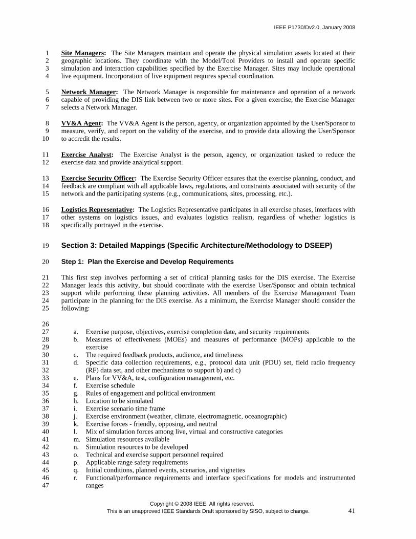
IEEE P1730/Dv2.0, January 2008
Copyright © 2008 IEEE. All rights reserved. This is an unapproved IEEE Standards Draft sponsored by SISO, subject to change. 41
Site Managers: The Site Managers maintain and operate the physical simulation assets located at their 1 geographic locations. They coordinate with the Model/Tool Providers to install and operate specific 2 simulation and interaction capabilities specified by the Exercise Manager. Sites may include operational 3 live equipment. Incorporation of live equipment requires special coordination. 4
Network Manager: The Network Manager is responsible for maintenance and operation of a network 5 capable of providing the DIS link between two or more sites. For a given exercise, the Exercise Manager 6 selects a Network Manager. 7
VV&A Agent: The VV&A Agent is the person, agency, or organization appointed by the User/Sponsor to 8 measure, verify, and report on the validity of the exercise, and to provide data allowing the User/Sponsor 9 to accredit the results. 10
Exercise Analyst: The Exercise Analyst is the person, agency, or organization tasked to reduce the 11 exercise data and provide analytical support. 12
Exercise Security Officer: The Exercise Security Officer ensures that the exercise planning, conduct, and 13 feedback are compliant with all applicable laws, regulations, and constraints associated with security of the 14 network and the participating systems (e.g., communications, sites, processing, etc.). 15
Logistics Representative: The Logistics Representative participates in all exercise phases, interfaces with 16 other systems on logistics issues, and evaluates logistics realism, regardless of whether logistics is 17 specifically portrayed in the exercise. 18
Section 3: Detailed Mappings (Specific Architecture/Methodology to DSEEP) 19
Step 1: Plan the Exercise and Develop Requirements 20
This first step involves performing a set of critical planning tasks for the DIS exercise. The Exercise 21 Manager leads this activity, but should coordinate with the exercise User/Sponsor and obtain technical 22 support while performing these planning activities. All members of the Exercise Management Team 23 participate in the planning for the DIS exercise. As a minimum, the Exercise Manager should consider the 24 following: 25
26 a. Exercise purpose, objectives, exercise completion date, and security requirements 27 b. Measures of effectiveness (MOEs) and measures of performance (MOPs) applicable to the 28
exercise 29 c. The required feedback products, audience, and timeliness 30 d. Specific data collection requirements, e.g., protocol data unit (PDU) set, field radio frequency 31
(RF) data set, and other mechanisms to support b) and c) 32 e. Plans for VV&A, test, configuration management, etc. 33 f. Exercise schedule 34 g. Rules of engagement and political environment 35 h. Location to be simulated 36 i. Exercise scenario time frame 37 j. Exercise environment (weather, climate, electromagnetic, oceanographic) 38 k. Exercise forces - friendly, opposing, and neutral 39 l. Mix of simulation forces among live, virtual and constructive categories 40 m. Simulation resources available 41 n. Simulation resources to be developed 42 o. Technical and exercise support personnel required 43 p. Applicable range safety requirements 44 q. Initial conditions, planned events, scenarios, and vignettes 45 r. Functional/performance requirements and interface specifications for models and instrumented 46
ranges 47
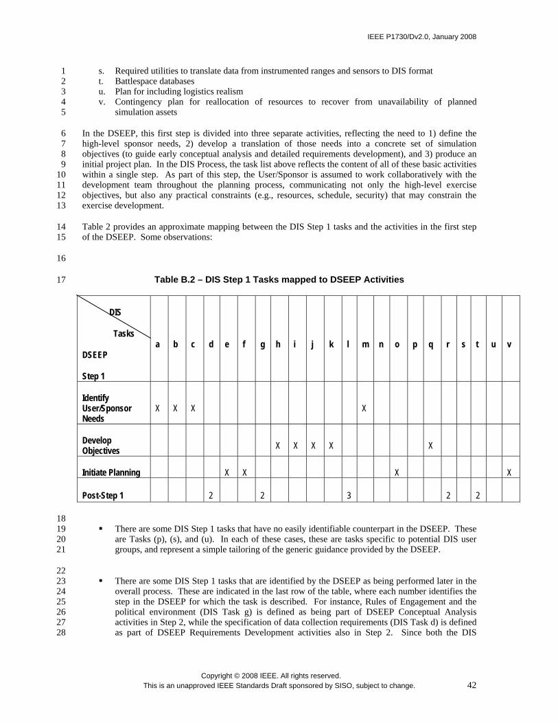
IEEE P1730/Dv2.0, January 2008
Copyright © 2008 IEEE. All rights reserved. This is an unapproved IEEE Standards Draft sponsored by SISO, subject to change. 42
s. Required utilities to translate data from instrumented ranges and sensors to DIS format 1 t. Battlespace databases 2 u. Plan for including logistics realism 3 v. Contingency plan for reallocation of resources to recover from unavailability of planned 4
simulation assets 5
In the DSEEP, this first step is divided into three separate activities, reflecting the need to 1) define the 6 high-level sponsor needs, 2) develop a translation of those needs into a concrete set of simulation 7 objectives (to guide early conceptual analysis and detailed requirements development), and 3) produce an 8 initial project plan. In the DIS Process, the task list above reflects the content of all of these basic activities 9 within a single step. As part of this step, the User/Sponsor is assumed to work collaboratively with the 10 development team throughout the planning process, communicating not only the high-level exercise 11 objectives, but also any practical constraints (e.g., resources, schedule, security) that may constrain the 12 exercise development. 13
Table 2 provides an approximate mapping between the DIS Step 1 tasks and the activities in the first step 14 of the DSEEP. Some observations: 15
16
Table B.2 – DIS Step 1 Tasks mapped to DSEEP Activities 17
DIS
Tasks
DSEEP
Step 1
a b c d e f g h i j k l m n o p q r s t u v
Identify User/Sponsor Needs
X X X X
Develop Objectives X X X X X
Initiate Planning X X X X
Post-Step 1 2 2 3 2 2
18 There are some DIS Step 1 tasks that have no easily identifiable counterpart in the DSEEP. These 19
are Tasks (p), (s), and (u). In each of these cases, these are tasks specific to potential DIS user 20 groups, and represent a simple tailoring of the generic guidance provided by the DSEEP. 21
22 There are some DIS Step 1 tasks that are identified by the DSEEP as being performed later in the 23
overall process. These are indicated in the last row of the table, where each number identifies the 24 step in the DSEEP for which the task is described. For instance, Rules of Engagement and the 25 political environment (DIS Task g) is defined as being part of DSEEP Conceptual Analysis 26 activities in Step 2, while the specification of data collection requirements (DIS Task d) is defined 27 as part of DSEEP Requirements Development activities also in Step 2. Since both the DIS 28

IEEE P1730/Dv2.0, January 2008
Copyright © 2008 IEEE. All rights reserved. This is an unapproved IEEE Standards Draft sponsored by SISO, subject to change. 43
Process and the DSEEP allow for considerable flexibility in the timing of required activities and 1 tasks, this is not considered to be a significant problem. 2
3 While the DIS Process only identifies planning activities as part of Step 1, the DSEEP identifies 4
initial planning activities as part of Step 1, and detailed planning as part of Step 3. However, it is 5 expected that updates to plans developed to support a DIS exercise will be modified as needed as 6 the development progresses, and thus there is no real difference here. 7
8 In terms of products, the main product produced by the first step of the DIS process is the project 9
plan, which reflects the collective outcome of all the Step 1 tasks. However, the DSEEP has 10 products for all of its Step 1 activities, specifically the Needs Statement, the Objectives Statement, 11 and the initial project plan. This does not mean that the DIS Process does not capture the same 12 information; it simply means that DIS users generally choose to merge the contents of these three 13 DSEEP products into a single product. Note that there is nothing in the DIS Process to preclude 14 users and developers from producing additional products if they wish. The single product is just a 15 reasonable tailoring of generic DSEEP guidance, which can be altered based upon the specific 16 needs of the application. 17
18
Step 2: Design, Construct, and Test Exercise 19
In this step of the DIS Process, the Exercise Architect develops the DIS exercise to meet the requirements 20 specified during the planning phase, making maximum reuse of existing DIS components. The Exercise 21 Manager, along with the Model/Tool Providers, plays a major role in the design and construction of the 22 exercise. The exercise development includes selection or development of components such as simulation 23 applications, databases, architecture, and environment. 24
This DIS Process step consists of a sequence of five phases: conceptual design, preliminary design, 25 detailed design, construction and assembly, and integration and testing. The following describes each of 26 these phases, along with its mapping to DSEEP steps or activities. 27
Conceptual Design: 28
In this phase, the Exercise Architect develops the conceptual model and top-level architecture for the 29 exercise that shows the participating components, their interfaces, behavior, and control structure. This 30 maps quite closely to Step 2 (Perform Conceptual Analysis) of the DSEEP. However, DSEEP Step 2 31 focuses mainly on the specification of the domain in software-independent terms, while the corresponding 32 DIS phase begins to extend this into the software domain (to some degree) to more effectively bridge into 33 preliminary design. DSEEP Step 2 also includes additional activities related to detailed requirements and 34 scenario development, which the DIS Process identifies as a Step 1 activity. 35
Preliminary Design: 36
In this phase, the Exercise Architect translates the requirements developed during the planning phase into a 37 preliminary DIS exercise. This includes development of scenario(s), mission plans for various participants, 38 database and map development and distribution, communications network design and tests, and planning 39 for training and rehearsals. 40
This DIS Process phase maps most closely to DSEEP Step 3 (Design Simulation Environment). However, 41 the DSEEP defines only a single simulation environment design effort instead of separate preliminary and 42 detailed design phases. Lower-level differences are defined below under Detailed Design. 43
Detailed Design: 44
IEEE P1730/Dv2.0, January 2008
Copyright © 2008 IEEE. All rights reserved. This is an unapproved IEEE Standards Draft sponsored by SISO, subject to change. 44
In this phase, the Exercise Architect works with the Exercise Manager to elaborate on the design model 1 and architecture generated in the previous step to the extent necessary to support and complete the 2 definition of all required functions, data flow, and behavior. The Exercise Architect and Exercise Manager 3 specifically include communication data rate requirements and data latency limitation requirements. 4
The preliminary and detailed design phases together map to DSEEP Step 3. However, there are some 5 differences. In the DSEEP, Step 3 is when the exercise participants are selected based on their ability to 6 meet the exercise requirements specified in Step 2. In the DIS Process, selection of participating 7 simulations occurs earlier during project planning, although supplementary (or alternative) exercise 8 participants can always be added as requirements change. DSEEP Step 3 also includes a specific activity 9 to translate the initial project plan into a more detailed plan for development and execution. Although this 10 is not identified as a separate activity in the DIS Process, it is understood that the project plan will continue 11 to be refined as necessary throughout the development process. Finally, this phase of the DIS Process 12 allows for some degree of database development, while this type of development activity is normally 13 considered part of Step 4 in the DSEEP. 14
Construction and Assembly 15
In this phase, the Exercise Manager, with the assistance of the Model/Tool Providers and the Exercise 16 Security Officer, assembles existing DIS components and develops new components that meet all security 17 requirements. This phase maps to DSEEP Step 4. However, DSEEP Step 4 provides a more detailed 18 breakdown of the activities required to construct and assemble an exercise, such as establishing agreements 19 among exercise participants on supporting resources (e.g., data sources, common algorithms), 20 implementing required modifications to individual exercise participants, and establishing the underlying 21 simulation infrastructure. In the DIS Process, such activities are simply assumed to occur as required 22 during construction/assembly. 23
In Step 4 of the DSEEP, there is also an activity dedicated to the development of the Information Exchange 24 Data Model (IEDM). Since DIS does not have the concept of an IEDM, there is no mention of such an 25 activity in the DIS Process. However, it is necessary for all participants in a DIS exercise to agree on 26 precisely what PDUs are to be used for a given exercise. Collectively, this selected set is roughly 27 comparable to the notion of an IEDM as it is used in the DSEEP. 28
Integration and Testing 29
In this phase, the Exercise Manager and Exercise Architect work this activity as an incremental process, 30 starting with a minimum number of components and connectivity, then adding and building until they 31 reach operational status. They then test to determine whether or not requirements and performance criteria 32 are met. The exercise support personnel are also trained and rehearsed (dry run). 33
This phase maps very closely to DSEEP Step 5. Like the preceding phase, the DSEEP describes this 34 activity in more depth, placing a special emphasis on the planning aspects of integration and test. 35 However, the basic series of tasks is essentially the same between the two processes. In fact, the 36 incremental nature of the DIS testing process as described above maps very well with the three-layered 37 testing approach (member testing, integration testing, interoperability testing) described in the DSEEP. 38
39
Step 3: Conduct Exercise 40
In this step of the DIS Process, the Exercise Manager conducts the DIS exercise using the resources 41 developed during the design, construct, and test phase. The goal of this third phase is to satisfy the 42 established objectives. The Exercise Manager is responsible for all necessary management functions. 43
This step of the DIS Process maps to DSEEP Step 6. The DSEEP is more explicit about the tasks required 44 to ensure proper execution management and runtime data collection, but it is understood that these same 45

IEEE P1730/Dv2.0, January 2008
Copyright © 2008 IEEE. All rights reserved. This is an unapproved IEEE Standards Draft sponsored by SISO, subject to change. 45
tasks occur in DIS exercises. The DSEEP also identifies a specific activity for post-processing raw 1 exercise outputs. The purpose of this activity is primarily data reduction, although translation into desired 2 formats may also be necessary in preparation for data analysis activities in the next step. 3
Step 4: Conduct Exercise Review Activity 4
In this step of the DIS Process, a review of the exercise is conducted. The exercise review activity may 5 initially center on rapidly providing after-action review material. The Exercise Manager can recall events 6 or situations marked with observed event markers in the data log and incorporate the data into presentation 7 material. Topics about which the Exercise Manager may wish to draw material for analysis and feedback 8 include interactions, communications, Rules and Engagement, logistics, and command decisions. From this 9 material, analysts and exercise participants can attempt to develop an understanding of the exercise and of 10 the decision-making processes based on what each participant knew and perceived at a given time. The 11 Exercise Analysts may want to obtain tools to select, integrate, and display exercise data for these 12 purposes. These data can also be supplemented by information provided by exercise observers and analysts 13 located with the exercise participants during the conduct of the exercise. The Exercise Manager must work 14 with the Exercise Architect who will task the Model/Tool Providers to develop tools to select, integrate, 15 and display exercise data. Additionally, the Exercise Manager ensures that exercise data is archived for 16 future cross-exercise analysis. 17
The exercise feedback system should include various data presentation methods. The exercise feedback 18 system should also provide a selection of analytical functions for preliminary analysis and after-action 19 review of each exercise, as well as support the bulk of post-exercise data consolidation and analysis task. 20
This step of the DIS Process maps to the first activity (Analyze Data) within DSEEP Step 7. The DSEEP 21 provides less detail than the DIS Process for this activity, as the rather concise, generic guidance provided 22 by the DSEEP has been translated into more detailed instructions for DIS users. However, at the task 23 level, the processes are entirely consistent. 24
Step 5: Provide Results to Decision-Makers 25
In this step of the DIS Process, exercise results are reported to designated levels of User/Sponsor and other 26 audiences according to the reporting requirements of the exercise. These results may include the following: 27
28 Exercise credibility 29 Cause and effect relationships 30 Detail and aggregation 31 Analysis 32 Exercise improvement 33
This step of the DIS Process maps to the second activity (Evaluate and Feedback Results) within DSEEP 34 Step 7. While the DIS Process is more specific about the classes of results that can be provided to the 35 User/Sponsor, the DSEEP includes an additional task for archiving all reusable products produced 36 throughout the development/execution process. In general, the DSEEP is more explicit about identifying 37 such products, and is the reason why the reusability of these products is emphasized more strongly in the 38 DSEEP. 39
Section 4: References (Annex-specific) 40
IEEE Std 1278™-1993, IEEE Standard for Information Technology – Protocols for Distributed Interaction 41 Simulation Applications910. 42
9 The IEEE products referred to in this clause are trademarks belonging to the Institute of Electrical and Electronics Engineers, Inc.

IEEE P1730/Dv2.0, January 2008
Copyright © 2008 IEEE. All rights reserved. This is an unapproved IEEE Standards Draft sponsored by SISO, subject to change. 46
IEEE Std 1278.1™-1995, IEEE Standard for Distributed Interaction Simulation – Application Protocols. 1
IEEE Std 1278.2™-1995, IEEE Standard for Distributed Interaction Simulation – Communication Services 2 and Profiles. 3
IEEE Std 1278.3™-1996, IEEE Recommended Practice for Distributed Interaction Simulation – Exercise 4 Management and Feedback. 5
IEEE Std 1278.1a™-1998, IEEE Standard for Distributed Interaction Simulation – Application Protocols 6 (supplement to IEEE Std 1278.1-1995). 7
8
10 IEEE publications are available from the Institute of Electrical and Electronics Engineers, 445 Hoes Lane, P.O. Box 1331, Piscataway, NJ 08855-1331, USA (http://standards.ieee.org/).


![Brookfield DV2 D[1]](https://img.pdfslide.us/doc/110x75/546041d6af795930708b5299/brookfield-dv2-d1.jpg)