Embed Size (px)
Citation preview

1
HV Bias Power Patch Panel for Scintillator KLM Gerard Visser Xiaowen Shi
2015-07-16
overview
Schematics
layout
Parts
2
SY2527LC 6 slots
6 ch x 2 DB-37 female connectors
…. up to 6modules
5x Patch panel
4 requiredFor EKLM
DB-37 cable 5ft
M-F >VW-1….
x3 CAEN SY2527LC crates
It requires at least 25(19+6)PS cables, which then requires13 HV modules.
Inventory:16 CAEN A1510 P.S.4 CAEN SY2527LC MF
A1510HV Module
SY2527LC
4x BKLM FEE crate(8 M.B + 8 RHIC)
DB-25 cable
M-->7 or
8 pairs
At FEE
8x EKLM FEE crate(14 M.B + 14 RHIC)
8 pairs to the FEE
7 pairs to the FEE
1 requiredFor BKLM…...
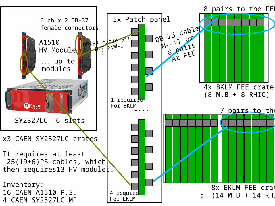
3
0.093'' thick
Male connectors
Femal connectors
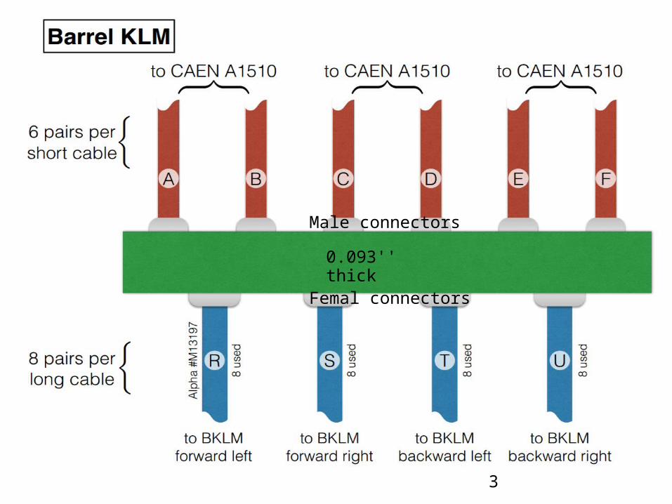
4
0.093'' thick
Femal connectors
Male connectors
5
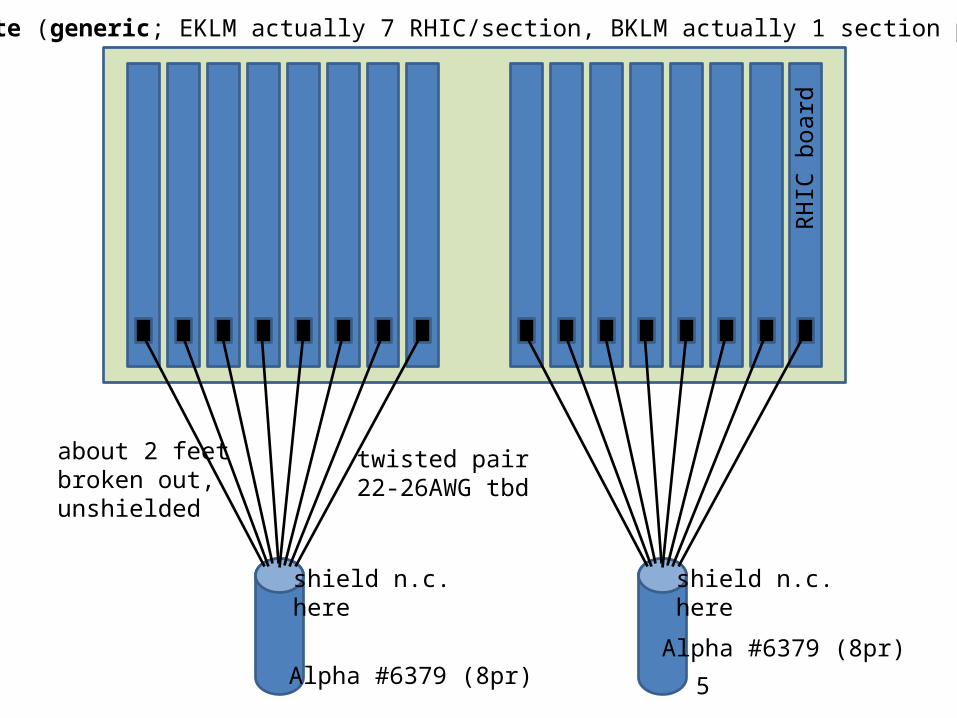
shield n.c.here
shield n.c.here
twisted pair22-26AWG tbd
Scinti FEE crate (generic; EKLM actually 7 RHIC/section, BKLM actually 1 section per crate not 2)
RHIC
boa
rd
Alpha #6379 (8pr)Alpha #6379 (8pr)
about 2 feet broken out, unshielded
6
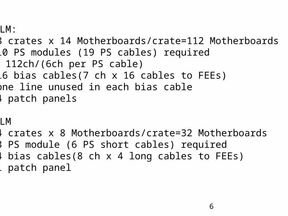
EKLM:• 8 crates x 14 Motherboards/crate=112 Motherboards• 10 PS modules (19 PS cables) required
112ch/(6ch per PS cable)• 16 bias cables(7 ch x 16 cables to FEEs)• one line unused in each bias cable• 4 patch panels
BKLM• 4 crates x 8 Motherboards/crate=32 Motherboards• 3 PS module (6 PS short cables) required• 4 bias cables(8 ch x 4 long cables to FEEs)• 1 patch panel
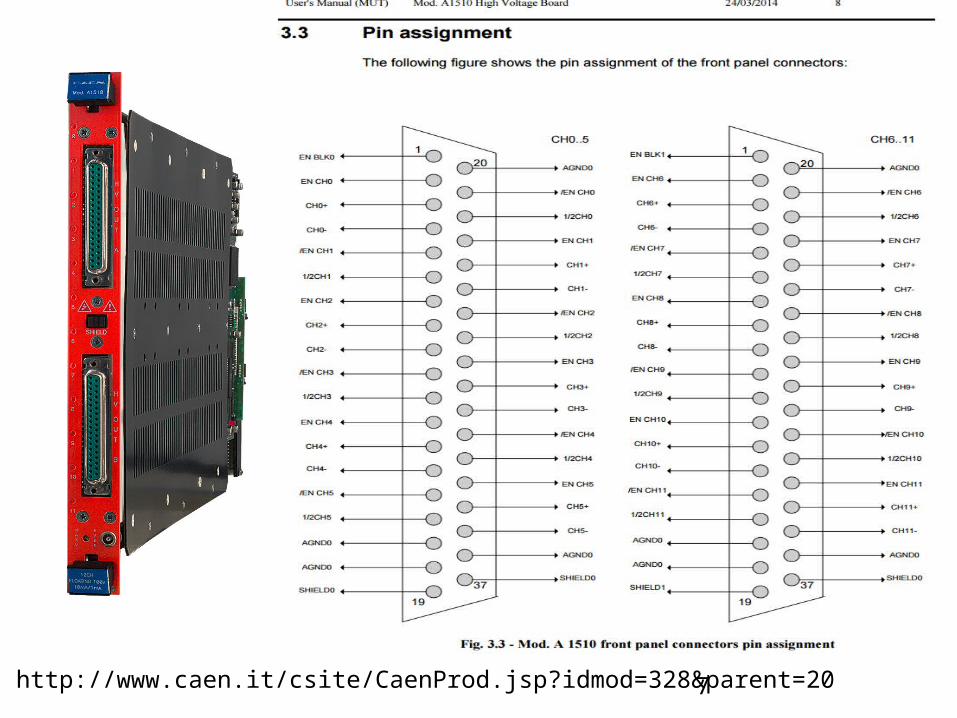
7http://www.caen.it/csite/CaenProd.jsp?idmod=328&parent=20
8
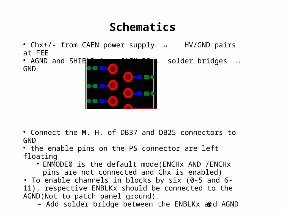
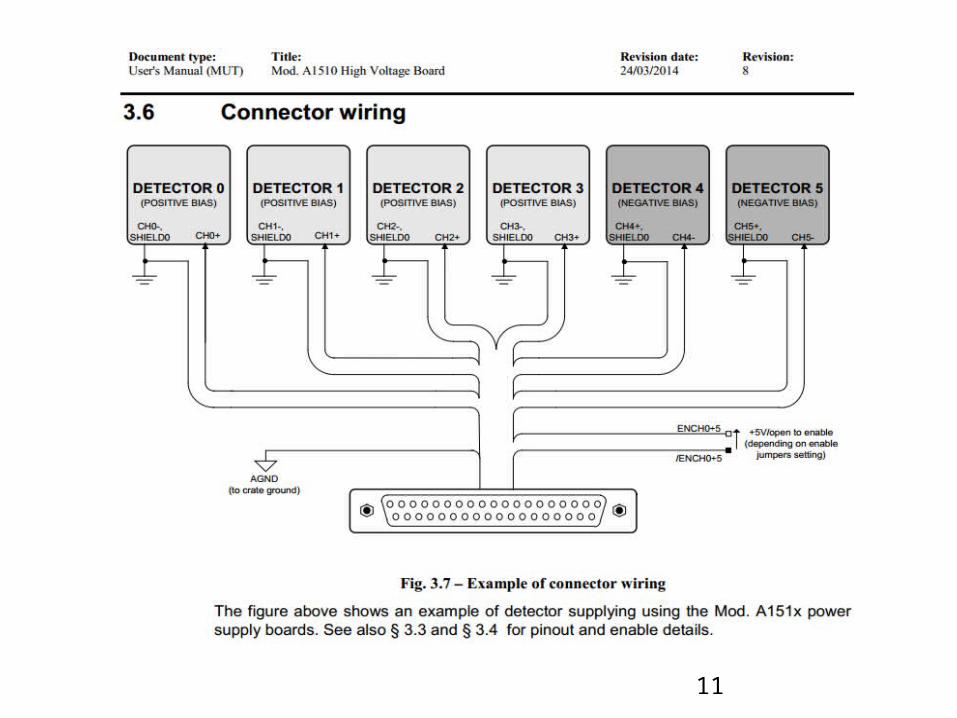
Schematics Chx+/- from CAEN power supply ↔ HV/GND pairs at FEE AGND and SHIELD from CAEN PS ↔ solder bridges ↔ GND
Connect the M. H. of DB37 and DB25 connectors to GND the enable pins on the PS connector are left floating
ENMODE0 is the default mode(ENCHx AND /ENCHx pins are not connected and Chx is enabled)
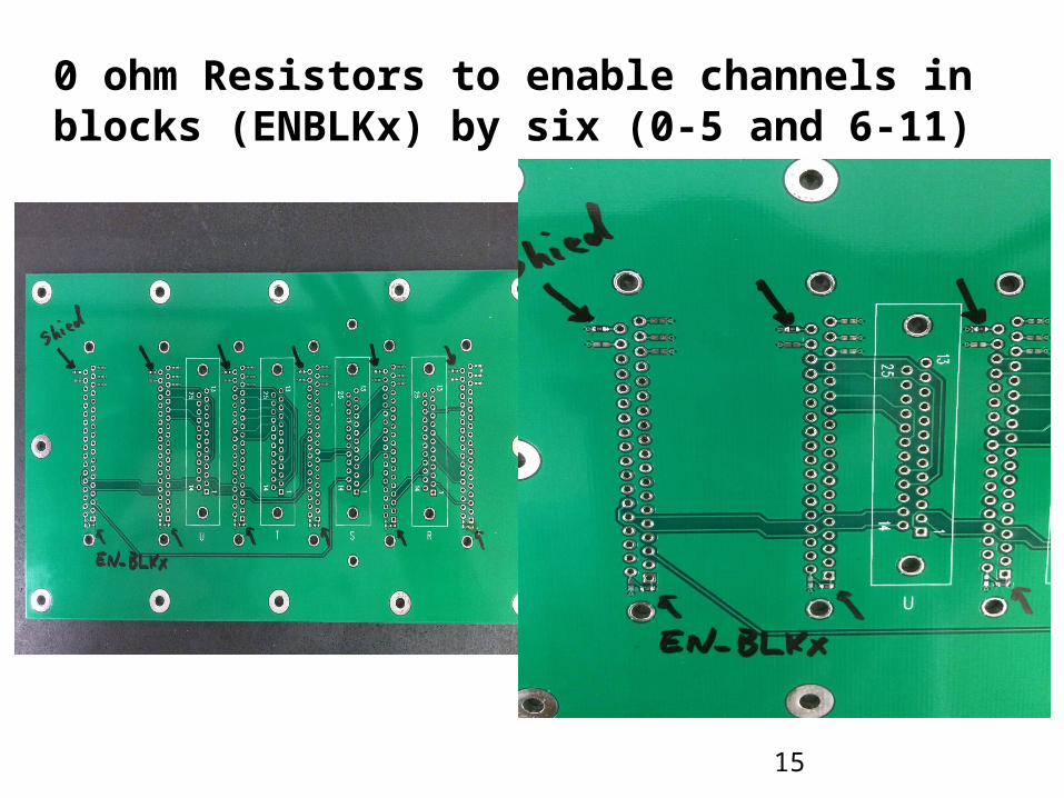
• To enable channels in blocks by six (0-5 and 6-11), respective ENBLKx should be connected to the AGND(Not to patch panel ground).
– Add solder bridge between the ENBLKx and AGND
Leave rest of the pins floating Link to the schematics[pdf] [PADS file]
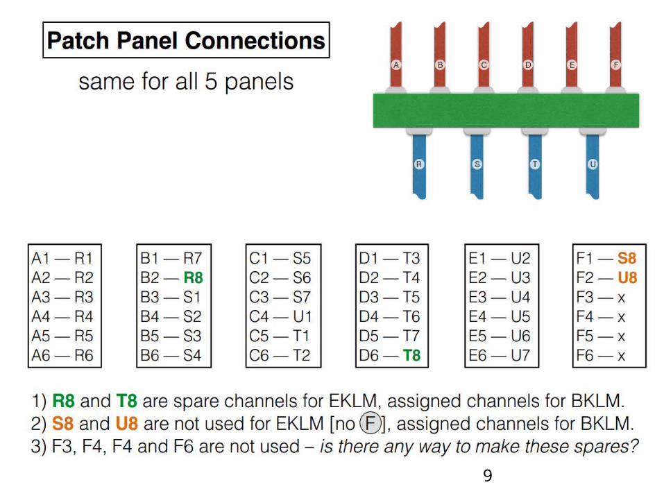
9
10
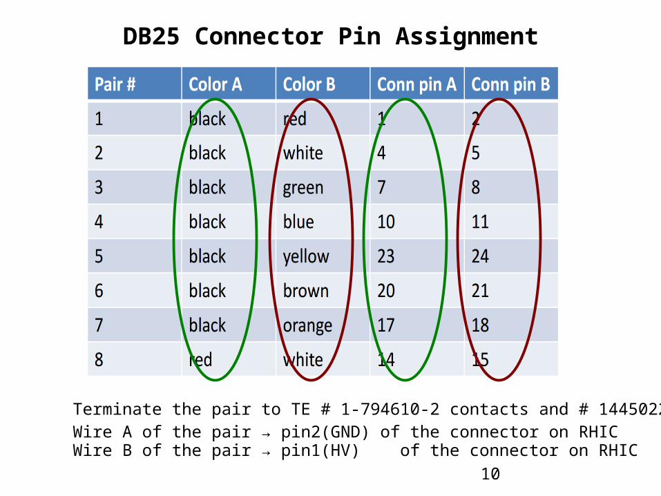
DB25 Connector Pin Assignment
Wire A of the pair → pin2(GND) of the connector on RHICWire B of the pair → pin1(HV) of the connector on RHIC
Terminate the pair to TE # 1-794610-2 contacts and # 1445022-2 pin housing.
11
12
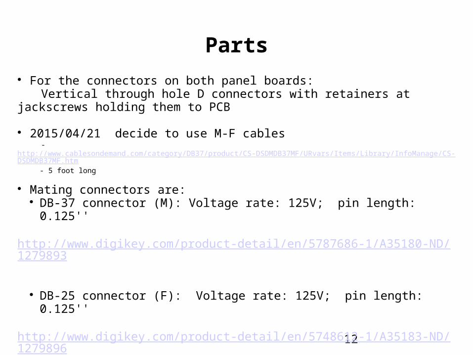
Parts For the connectors on both panel boards:
Vertical through hole D connectors with retainers at jackscrews holding them to PCB
2015/04/21 decide to use M-F cables- http://www.cablesondemand.com/category/DB37/product/CS-DSDMDB37MF/URvars/Items/Library/InfoManage/CS-DSDMDB37MF.htm- 5 foot long
Mating connectors are: DB-37 connector (M): Voltage rate: 125V; pin length: 0.125''
http://www.digikey.com/product-detail/en/5787686-1/A35180-ND/1279893
DB-25 connector (F): Voltage rate: 125V; pin length: 0.125''http://www.digikey.com/product-detail/en/5748612-1/A35183-ND/1279896
13
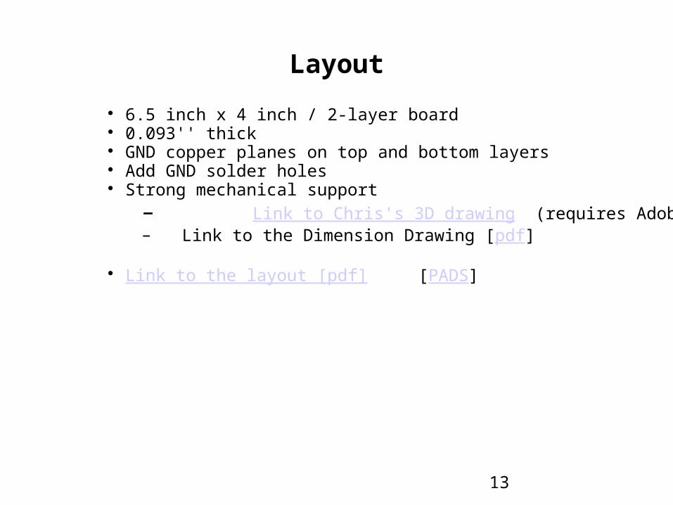
Layout
6.5 inch x 4 inch / 2-layer board 0.093'' thick GND copper planes on top and bottom layers Add GND solder holes Strong mechanical support
– Link to Chris's 3D drawing (requires Adobe)– Link to the Dimension Drawing [pdf]
Link to the layout [pdf] [PADS]
14
Chris's email
Here is a preliminary idea for the patch panel support. (You must download file and open through Adobe to get 3D to work.) I have a few suggestions I would like to make, then, pending your agreement,
I will be ready to share model with others for comments. 1. Holes are not symmetric with respect to board outline. 2. Adding 2 more mounting holes would make this much tougher. 3. If board was bigger, say 4.5 x 7 inches, then I could make the cutouts in the patch panel bigger and have more room for connectors to plug in.
Here is the link to the bolt we should use. http://www.mcmaster.com/#91292a110/=x1fvxn
Finished hole size of 134 mil will allow manufacturer to use a #29 drill bit (136 mil). This will give 16 mils of play around the bolt, which is regarded as a "loose fit."
15
0 ohm Resistors to enable channels in blocks (ENBLKx) by six (0-5 and 6-11)
16
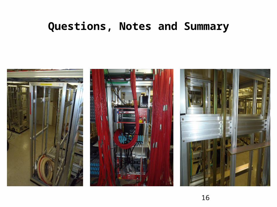
Questions, Notes and Summary