Embed Size (px)
Citation preview
Dri
lling
1 HSS drilling
2 Solid carbide drilling
3 Indexable insert drilling
4 Reaming and Countersinking
Thre
adin
g
5 HSS taps and dies
6 Circular and Thread Milling
7 Thread turning
Turn
ing
8 Turning Tools
9 EcoCut + ProfileMaster
10 Grooving Tools 10
11 Miniature turning tools
Mill
ing
12 HSS Milling Cutters
13 Solid Carbide milling cutters
14 Milling tools with indexable inserts + mould and die production
Tool
Hol
ders
15 Rotating toolholders
16 Tool holders, static + driven tools
17 Vices
Mod
ular
To
olho
lder
s
18 Modular Spindle Tools
19 Article no. index
New products for machining technicians
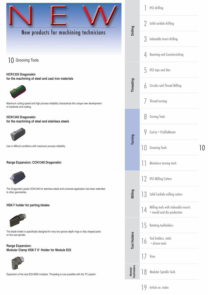
10 Grooving Tools
HCR1335 Dragonskin for the machining of steel and cast iron materials
Maximum cutting speed and high process reliability characterize this unique new development of substrate and coating.
HCN1345 Dragonskin for the machining of steel and stainless steels
Use in difficult conditions with maximum process reliability.
Range Expansion: CCN1340 Dragonskin
The Dragonskin grade CCN1340 for stainless steels and universal application has been extended to other geometries.
HSK-T holder for parting blades
The blade holder is specifically designed for very low groove depth rings or disc shaped parts on the sub-spindle.
Range Expansion: Modular Clamp HSK-T 0° Holder for Module E25
Expansion of the size E25 MSS modules. Threading is now possible with the TC system.

10 / 2 toolingcenter.com
Table of contents
Chip Breaker Types and Grade Overview Page(s) 3
Navigation through the grooving range - External machining Page(s) 4-5
Navigation through the grooving range - Internal machining Page(s) 6-7
WNT- Tipp Page(s) 8-9
Torque values for module and insert clamping Page(s) 100
Technical Information Page(s) 97-110
Chip breaker application values Page(s) 111-113
Cutting Data Page(s) 114-117
Quick selection guide of the systems
GX grooving system Page(s) 11-42
SX grooving system Page(s) 43-51
FX grooving system Page(s) 52-60
AX grooving system Page(s) 61-62
LX grooving system Page(s) 63-65
TC grooving system (thread machining) Page(s) 66-73
TX grooving system Page(s) 74-82
MaxiClick grooving system Page(s) 83-88
Basic holder for modular system Page(s) 89-93
Page(s) 94-96
WNT Mastertool Dragonskin
Technologically advanced procedures when applying the coatings improve capability characteristics to the highest quality. The specifically developed surface treatment minimizes friction against the workpiece to a minimum and improves chip flow substantially. WNT Mastertool Dragonskin coatings are unbeatable in universal use and offer maximum process security, security against breakage as well as service life.
HCF 1325 / HCR 1335 / HCN 1345
Unalloyed, low alloyed and high alloyed steel
CCN 1340
Austenitic, martensitic and ferritic stainless steel
Grooving Tools
toolingcenter.com 10 / 3
10
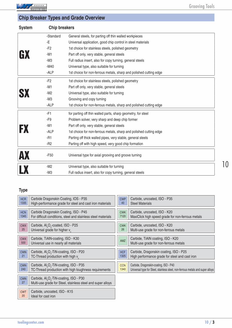
Chip Breaker Types and Grade Overview
Type
HCR1335
Carbide Dragonskin Coating, IOS - P35 High-performance grade for steel and cast iron materials
CWP40
Carbide, uncoated, ISO - P35 Steel Materials
HCN1345
Carbide Dragonskin Coating, ISO - P45 For difficult conditions, steel and stainless steel materials
CWK7120
Carbide, uncoated, ISO - K20 MaxiClick high speed grade for non-ferrous metals
CWX25
Carbide, Al2O
3-coated, ISO - P25
Universal grade for higher vc
CWK26
Carbide, uncoated, ISO - K20 Multi-use grade for non-ferrous metals
CWX500
Carbide, TiAlN-coating, ISO - K30 Universal use in nearly all materials
AMZCarbide, TiAlN coating, ISO - K20 Multi-use grade for non-ferrous metals
CWN21
Carbide, Al2O
3-TiN-coating, ISO - P20
TC-Thread production with high vc
HCF1325
Carbide, Dragonskin coating, ISO - P25 High performance grade for steel and cast iron
CWN240
Carbide, Al2O
3-TiN-coating, ISO - P35
TC-Thread production with high toughness requirementsCCN1340
Carbide, Dragonskin-coating, ISO - P40 Universal type for Steel, stainless steel, non-ferrous metals and super alloys
CWN27
Carbide, Al2O
3-TiN-coating, ISO - P30
Multi-use grade for Steel, stainless steel and super alloys
CWT20
Carbide, uncoated, ISO - K15 Ideal for cast iron
System Chip breakers
GX
-Standard General steels, for parting off thin walled workpieces
-E Universal application, good chip control in steel materials
-F2 1st choice for stainless steels, polished geometry
-M1 Part off only, very stable, general steels
-M3 Full radius insert, also for copy turning, general steels
-M40 Universal type, also suitable for turning
-ALP 1st choice for non-ferrous metals, sharp and polished cutting edge
SX
-F2 1st choice for stainless steels, polished geometry
-M1 Part off only, very stable, general steels
-M2 Universal type, also suitable for turning
-M3 Grooving and copy turning
-ALP 1st choice for non-ferrous metals, sharp and polished cutting edge
FX
-F1 for parting off thin walled parts, sharp geometry, for steel
-F9 Problem solver, very sharp and deep chip former
-M1 Part off only, very stable, general steels
-ALP 1st choice for non-ferrous metals, sharp and polished cutting edge
-R1 Parting off thick walled pipes, very stable, general steels
-R2 Parting off with high speed, very good chip formation
AX -F50 Universal type for axial grooving and groove turning
LX-M2 Universal type, also suitable for turning
-M3 Full radius insert, also for copy turning, general steels
Grooving Tools

10 / 4 toolingcenter.com
-M40
-F2
GX 24Radial, axial and deep axial grooving and parting, face turning and turning
Cutting widths = 2,0 - 6,0 mm
70 363 ... Page 30
70 364 ... Page 32
70 350 ... Page 29
70 350 ... Page 33
70 350 ... Page 34
70 354 ... Page 31
70 867 / 868 ...
Page 39
70 890 / 891 ...
Page 36
70 894 / 895 ...
Page 37
GX 16
Cutting widths = 0,5 - 5,15 mm (H13)
Circlip grooves
70 352 ... Page 12-13
70 352 ... Page 12-13
70 354 ... Page 14
70 354 ... Page 15
Radius grooves
70 354 ... Page 20
Grooving and Turning
Cutting widths = 2,0 - 6,0 mm
70 350 ... Page 11
70 351 ... Page 17
70 350 ... Page 19
70 362 ... Page 16
70 360 ... Page 18
70 870 / 871 ...
Page 21
70 865 / 866 ...
Page 22
GX 09
Cutting widths = 0,5 - 3,15 mm (H13)
Circlip grooves
70 352 ... Page 12-13
70 352 ... Page 12-13
70 354 ... Page 14
70 354 ... Page 15
Radius grooves
Grooving and Turning
Cutting widths = 2,0 - 3,5 mm
70 350 ... Page 11
70 351 ... Page 17
70 360 ... Page 18
70 870 / 871 ...
Page 21
70 865 / 866 ...
Page 22
70 852 / 853 ...
Page 90
70 854 / 855 ...
Page 91
70 850 / 851 ...
Page 89
Deep Radial Grooving, Parting and Turning
Axial Grooving and Face Turning
Deep Axial Grooving and Face Turning
70 862 / 863 ...
Page 25
70 888 / 889 ...
Page 26
70 862 / 863 ...
Page 41
70 834 ...
Page 40
Torque values for module and insert clamping Page 100Technical Information Page 97-110Chip breaker application values Page 111-113Cutting Data Page 114-117
-ALP
-M40
-ALP
-M1
-F2
-M40
-M1
-ALP
-F2
-M3
Cutting widths = 3,0 - 8,0 mm
70 353 ... Page 35
-M40
-F2
-ALP
Grooving Tools

toolingcenter.com 10 / 5
10
Steel
Stainless steel
Cast iron
Non ferrous metals
Heat resistant alloys
Hardened materials
MaxiClickParting and Grooving
Cutting widths = 1,0 - 2,5 mm
70 338 ... Page 83
70 339 ... Page 84
70 340 ... Page 85
70 341 ... Page 86
5 mm
10 mm
External Machining
LX
Cutting widths = 8,0 - 10,0 mm
Deep Parting and Grooving
70 337... Page 63
70 337 ... Page 63
FXParting and Grooving
Cutting widths = 2,2 - 9,7 mm
70 331 ... Page 52
70 330 ...70 332 ...
Page 53-55
70 335 ... Page 56
70 334 ... Page 57
TCThread turning
Partial profile 60°70 355 ...
Page 68
Partial profile 55°70 356 ...
Page 70
Full profile 60°70 357 ...
Page 66
Full profile 55°70 359 ...
Page 69
SX
Cutting widths = 2,0 - 4,0 mm
Parting, Grooving and Turning
70 343 ... Page 44
70 346 ... Page 46
Cutting widths = 2,0 - 6,0 mm
70 349 ... Page 47
70 835 ...
Page 64
70 872 ...
Page 71
70 875 / 876 ...
Page 5870 874 ...
Page 88
70 873 ...
Page 87
70 836 / 837 ...
Page 59
70 882 / 883 ...
Page 71
70 898 ...
Page 51
70 833 ...
Page 65
70 832 ...
Page 60
70 884 ...
Page 49
70 831 ...
Page 96
70 830 ...
Page 95
70 879 ...
Page 50
VDI-Adaptor
Chapter 16
65 170 043
Page 30
-M2
-M3
-F1
-M1
-R2
-ALP
-F2
-M2
-ALP
-ALP
-F2
-F2
-F3
5 mm
10 mm
10 mm
10 mm
AX
Groove widths = 3,0 mm
Axial Grooving and Turning
70 327... Page 61
70 896 / 897 ...
Page 48
70 827 / 828 ...
Page 62
-F50
Page 74-82
74 582 / 583 ...
Page 93
74 580 / 581 ...
Page 93
70 344 ... Page 45
Cutting widths = 3,0 - 6,0 mm
-M3
70 342 ... Page 43
Parting and Grooving
Cutting widths = 2,0 - 6,0 mm
-M1
Grooving and copy turning
74 584 / 585 ...
Page 94
Grooving Tools

10 / 6 toolingcenter.com
70 860 / 861 ...
Page 92
70 860 / 861 ...
Page 92
-M40
-F2
GX 09
Cutting widths = 0,5 - 3,15 mm (H13)
Circlip grooves
70 352 ... Page 12-13
70 352 ... Page 12-13
70 354 ... Page 14
70 354 ... Page 15
Radius grooves
Grooving and Turning
Cutting widths = 2,0 - 3,5 mm
70 350 ... Page 11
70 351 ... Page 17
70 360 ... Page 18
-M40
-F2
70 885 / 886 ...
Page 24
70 880 / 881 ...
Page 23
70 858 / 859 ...
Page 27
GX 16
Cutting widths = 0,5 - 5,15 mm (H13)
Circlip grooves
70 352 ... Page 12-13
70 352 ... Page 12-13
70 354 ... Page 14
70 354 ... Page 15
Radius grooves
70 354 ... Page 20
Grooving and Turning
Cutting widths = 2,0 - 6,0 mm
70 350 ... Page 11
70 351 ... Page 17
70 350 ... Page 19
70 362 ... Page 16
70 360 ... Page 18
-ALP
-M40
-ALP
-M1
-F2
70 885 / 886 ...
Page 24
70 880 / 881 ...
Page 23
70 892 / 893 ...
Page 28
Torque values for module and insert clamping Page 100Technical Information Page 97-110Chip breaker application values Page 111-113Cutting Data Page 114-117
Grooving Tools
toolingcenter.com 10 / 7
10
Steel
Stainless steel
Cast iron
Non ferrous metals
Heat resistant alloys
Hardened materials
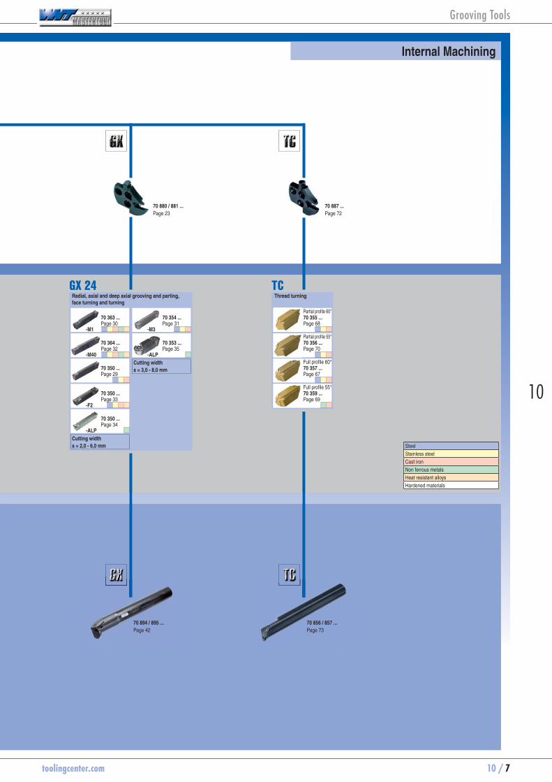
Internal Machining
GX 24Radial, axial and deep axial grooving and parting, face turning and turning
Cutting widths = 2,0 - 6,0 mm
70 363 ... Page 30
70 364 ... Page 32
70 350 ... Page 29
70 350 ... Page 33
70 350 ... Page 34
70 354 ... Page 31
-M40
-M1
-ALP
-F2
-M3
Cutting widths = 3,0 - 8,0 mm
70 353 ... Page 35
-ALP
70 880 / 881 ...
Page 23
70 894 / 895 ...
Page 42
TCThread turning
Partial profile 60°70 355 ...
Page 68
Partial profile 55°70 356 ...
Page 70
Full profile 60°70 357 ...
Page 67
Full profile 55°70 359 ...
Page 69
70 887 ...
Page 72
70 856 / 857 ...
Page 73
Grooving Tools

10 / 8 toolingcenter.com
Double ended axial groove system for grooving and groove turning with high precision. For the three different depths (5 mm, 10 mm and 15 mm) stable tools are available for each application.
Double ended grooving system with highest flexibility. Parting, grooving and groove-turning as well as the production of circlip grooves. Available in sizes GX09, GX16 and GX24.
Single ended system for extreme applications starting from groove width 8.0 mm. Use the LX-system under stable conditions.
A single edge parting system with a variety of specialized chip geometries. For fine machining of unstable parts to high speed machining under stable conditions.
Double ended thread turning system for the production of external and internal threads. Special design permits use without pitch angle correction on fine and coarse ranges of application
Three-edged grooving system for parting, grooving, axial grooving, radius grooving, copy and fine turning. Positive ground cutting geometries, with a very smooth cut with the lowest cutting forces. Universally applicable for almost all materials.
Grooving Tools

toolingcenter.com 10 / 9
10
HCF 1325
Universal high speed grade specifically for steel
HCR 1335
Grade for high speed and process security
HCN 1345
Adverse conditions such as interrupted cuts with maximum process reliability
CCN 1340
Specialist for stainless materials but universally applicable
CWK 26
For Aluminium with „WNT-Mastertool microfinish“ surface
WNT Mastertool Grades:
High Precision polished geometry - Repeatability ± 0,02 mm
Geometry for grooving and turning with very good chip control
All purpose geometry for parting, grooving & turning
Specially developed geometry with negative edge-chamfers available in right, left and neutral types
Parting Parting / Grooving and Turning
Specialist for aluminum and other soft long-chipping non-ferrous metals
The Single-ended SX-grooving system with the chip -M3 groove is even more versatile. Besides grooving / parting with the -F2, M2-, or WNT-ALP chip breakers, the new SX-M3 enables turning operations with the highest chip control. With this additional option, the SX-grooving system can be used as a universal grooving tool for all applications.
Grooving Tools

10 / 10 toolingcenter.com
Symbol explanation
Parting
Axial Grooving and Turning
Metric External thread
Metric Internal thread
Internal and External Whitworth thread
Circlip grooves
Grooving
Grooving and Turning
Grooving
Turning
Face turning
Axial grooving
Main application
Extended application
Repeatability
Type of product
HCF
1325Grade
Grooving tools are divided into two different systems:
- Modular grooving system in "ModularClamp"
- Mono grooving system in "MonoClamp"
Basic holder Grooving module Monobloc tool holder Grooving Blade
The name " ModularClamp" is valid for products with modules The name " MonoClamp" is valid for products without modules
Overview of all HSK-T holders can be found in Chapter 16 on pages 4-5.
Grooving Tools

toolingcenter.com 10 / 11
10
Insert GX 09/16 -Standard - Suitable for parting thin-walled workpieces
F M R
± 0,02 mm
l2
HCF
1325
CWN
27
HCR
1335
CCN
1340
CWX
25
PG 1C PG 1C PG 1C PG 1C PG 1CArticle no. Article no. Article no. Article no. Article no.
Designation l s
+/-0,02r
+/-0,05l2 for mo-
dules 70 350 ... 70 350 ... 70 350 ... 70 350 ... 70 350 ...
mm mm mm mm £ £ £ £ £GX 09-1 E2.00 N 0.20 9 2.0 0.2 1.5 GX 09-1 20.70 70350784 19.70 70350384 20.70 70350634 19.70 70350184GX 09-1 E2.50 N 0.20 9 2.5 0.2 1.5 GX 09-1 20.70 70350788 19.70 70350388 20.70 70350638 19.70 70350188GX 09-2 E3.00 N 0.30 9 3.0 0.3 2.0 GX 09-2 20.70 70350792 19.70 70350392 20.70 70350642 19.70 70350192GX 09-2 E3.50 N 0.30 9 3.5 0.3 2.0 GX 09-2 20.70 70350796 19.70 70350396 19.70 70350196 GX 16-1 E2.00 N 0.20 16 2.0 0.2 2.5 GX 16-1 21.06 70350700 20.16 70350400 21.06 70350500 21.06 70350600 20.16 70350200GX 16-1 E2.50 N 0.20 16 2.5 0.2 2.5 GX 16-1 21.06 70350704 20.16 70350404 21.06 70350504 21.06 70350604 20.16 70350204GX 16-2 E3.00 N 0.30 16 3.0 0.3 3.0 GX 16-2 21.06 70350708 20.16 70350408 21.06 70350508 21.06 70350608 20.16 70350208GX 16-2 E3.00 N 0.50 16 3.0 0.5 3.0 GX 16-2 21.06 70350710 20.16 70350210GX 16-2 E3.50 N 0.30 16 3.5 0.3 3.0 GX 16-2 21.06 70350712 20.16 70350412 21.06 70350512 21.06 70350612 20.16 70350212GX 16-3 E4.00 N 0.40 16 4.0 0.4 3.5 GX 16-3 23.06 70350716 21.97 70350416 23.06 70350516 23.06 70350616 21.97 70350216GX 16-3 E4.00 N 0.60 16 4.0 0.6 3.5 GX 16-3 23.06 70350718 21.97 70350218GX 16-3 E4.50 N 0.40 16 4.5 0.4 3.5 GX 16-3 23.06 70350720 21.97 70350220GX 16-3 E5.00 N 0.40 16 5.0 0.4 3.5 GX 16-3 23.06 70350724 21.97 70350424 23.06 70350524 23.06 70350624 21.97 70350224GX 16-3 E5.00 N 0.60 16 5.0 0.6 3.5 GX 16-3 23.06 70350726 21.97 70350226GX 16-4 E6.00 N 0.50 16 6.0 0.5 4.0 GX 16-4 24.33 70350728 23.15 70350428 24.33 70350628 23.15 70350228GX 16-4 E6.00 N 0.80 16 6.0 0.8 4.0 GX 16-4 24.33 70350730 23.15 70350230
Steel ● ● ● ● ●Stainless steel ○ ○ ○ ● ○Cast iron ● ● ●Non ferrous metals ○ Heat resistant alloys ○ ○ ● ○hardened materials ○ ○
page 115-116
Internal Machining External Machining
23-24 27-28 21-22 25-26
Grooving Tools
10 / 12 toolingcenter.com
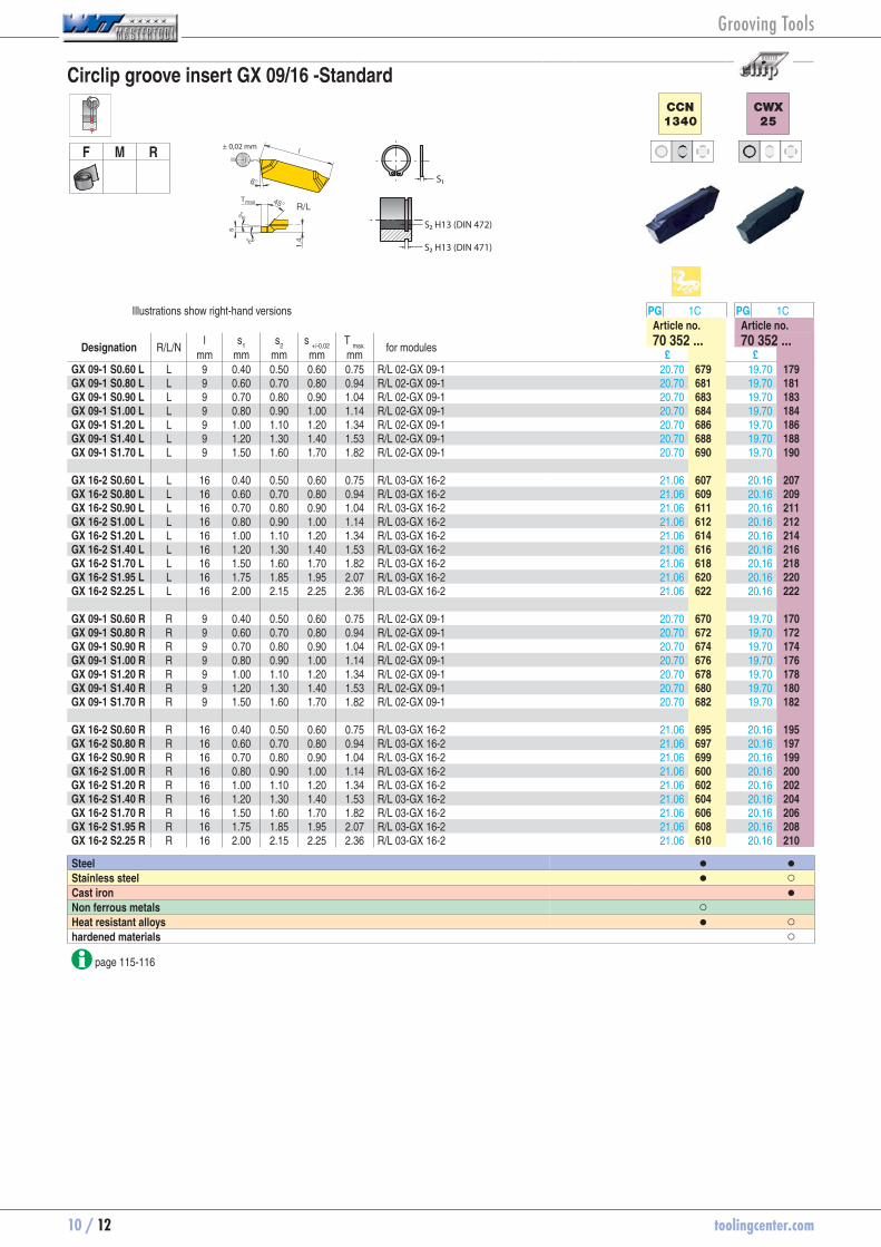
Circlip groove insert GX 09/16 -Standard
F M R± 0,02 mm
S2 H13 (DIN 472)
S2 H13 (DIN 471)
S1
CCN
1340
CWX
25
Illustrations show right-hand versions PG 1C PG 1CArticle no. Article no.
Designation R/L/N l s
1 s
2 s
+/-0,02T
max.
for modules 70 352 ... 70 352 ...mm mm mm mm mm £ £
GX 09-1 S0.60 L L 9 0.40 0.50 0.60 0.75 R/L 02-GX 09-1 20.70 70352679 19.70 70352179GX 09-1 S0.80 L L 9 0.60 0.70 0.80 0.94 R/L 02-GX 09-1 20.70 70352681 19.70 70352181GX 09-1 S0.90 L L 9 0.70 0.80 0.90 1.04 R/L 02-GX 09-1 20.70 70352683 19.70 70352183GX 09-1 S1.00 L L 9 0.80 0.90 1.00 1.14 R/L 02-GX 09-1 20.70 70352684 19.70 70352184GX 09-1 S1.20 L L 9 1.00 1.10 1.20 1.34 R/L 02-GX 09-1 20.70 70352686 19.70 70352186GX 09-1 S1.40 L L 9 1.20 1.30 1.40 1.53 R/L 02-GX 09-1 20.70 70352688 19.70 70352188GX 09-1 S1.70 L L 9 1.50 1.60 1.70 1.82 R/L 02-GX 09-1 20.70 70352690 19.70 70352190 GX 16-2 S0.60 L L 16 0.40 0.50 0.60 0.75 R/L 03-GX 16-2 21.06 70352607 20.16 70352207GX 16-2 S0.80 L L 16 0.60 0.70 0.80 0.94 R/L 03-GX 16-2 21.06 70352609 20.16 70352209GX 16-2 S0.90 L L 16 0.70 0.80 0.90 1.04 R/L 03-GX 16-2 21.06 70352611 20.16 70352211GX 16-2 S1.00 L L 16 0.80 0.90 1.00 1.14 R/L 03-GX 16-2 21.06 70352612 20.16 70352212GX 16-2 S1.20 L L 16 1.00 1.10 1.20 1.34 R/L 03-GX 16-2 21.06 70352614 20.16 70352214GX 16-2 S1.40 L L 16 1.20 1.30 1.40 1.53 R/L 03-GX 16-2 21.06 70352616 20.16 70352216GX 16-2 S1.70 L L 16 1.50 1.60 1.70 1.82 R/L 03-GX 16-2 21.06 70352618 20.16 70352218GX 16-2 S1.95 L L 16 1.75 1.85 1.95 2.07 R/L 03-GX 16-2 21.06 70352620 20.16 70352220GX 16-2 S2.25 L L 16 2.00 2.15 2.25 2.36 R/L 03-GX 16-2 21.06 70352622 20.16 70352222 GX 09-1 S0.60 R R 9 0.40 0.50 0.60 0.75 R/L 02-GX 09-1 20.70 70352670 19.70 70352170GX 09-1 S0.80 R R 9 0.60 0.70 0.80 0.94 R/L 02-GX 09-1 20.70 70352672 19.70 70352172GX 09-1 S0.90 R R 9 0.70 0.80 0.90 1.04 R/L 02-GX 09-1 20.70 70352674 19.70 70352174GX 09-1 S1.00 R R 9 0.80 0.90 1.00 1.14 R/L 02-GX 09-1 20.70 70352676 19.70 70352176GX 09-1 S1.20 R R 9 1.00 1.10 1.20 1.34 R/L 02-GX 09-1 20.70 70352678 19.70 70352178GX 09-1 S1.40 R R 9 1.20 1.30 1.40 1.53 R/L 02-GX 09-1 20.70 70352680 19.70 70352180GX 09-1 S1.70 R R 9 1.50 1.60 1.70 1.82 R/L 02-GX 09-1 20.70 70352682 19.70 70352182 GX 16-2 S0.60 R R 16 0.40 0.50 0.60 0.75 R/L 03-GX 16-2 21.06 70352695 20.16 70352195GX 16-2 S0.80 R R 16 0.60 0.70 0.80 0.94 R/L 03-GX 16-2 21.06 70352697 20.16 70352197GX 16-2 S0.90 R R 16 0.70 0.80 0.90 1.04 R/L 03-GX 16-2 21.06 70352699 20.16 70352199GX 16-2 S1.00 R R 16 0.80 0.90 1.00 1.14 R/L 03-GX 16-2 21.06 70352600 20.16 70352200GX 16-2 S1.20 R R 16 1.00 1.10 1.20 1.34 R/L 03-GX 16-2 21.06 70352602 20.16 70352202GX 16-2 S1.40 R R 16 1.20 1.30 1.40 1.53 R/L 03-GX 16-2 21.06 70352604 20.16 70352204GX 16-2 S1.70 R R 16 1.50 1.60 1.70 1.82 R/L 03-GX 16-2 21.06 70352606 20.16 70352206GX 16-2 S1.95 R R 16 1.75 1.85 1.95 2.07 R/L 03-GX 16-2 21.06 70352608 20.16 70352208GX 16-2 S2.25 R R 16 2.00 2.15 2.25 2.36 R/L 03-GX 16-2 21.06 70352610 20.16 70352210
Steel ● ●Stainless steel ● ○Cast iron ●Non ferrous metals ○ Heat resistant alloys ● ○hardened materials ○
page 115-116
Grooving Tools

toolingcenter.com 10 / 13
10
Circlip groove insert GX 09/16 -Standard
F M R
l2
± 0,02 mm
S2 H13 (DIN 472)
S2 H13 (DIN 471)
S1
CCN
1340
CWX
25
PG 1C PG 1CArticle no. Article no.
Designation l s
1 s
2 s
+/-0,02r
+/-0,05l2
for modules 70 352 ... 70 352 ...mm mm mm mm mm mm £ £
GX 09-1 S1.95 N 9 1.75 1.85 1.95 0.1 2.0 GX 09-1 20.70 70352692 19.70 70352192GX 09-1 S2.25 N 9 2.00 2.15 2.25 0.1 2.0 GX 09-1 20.70 70352694 19.70 70352194GX 09-2 S2.75 N 9 2.50 2.65 2.75 0.1 2.0 GX 09-2 20.70 70352696 19.70 70352196GX 09-2 S3.25 N 9 3.00 3.15 3.25 0.1 2.0 GX 09-2 20.70 70352698 19.70 70352198 GX 16-2 S2.75 N 16 2.50 2.65 2.75 0.1 3.0 GX 16-2 21.06 70352624 20.16 70352224GX 16-2 S3.25 N 16 3.00 3.15 3.25 0.1 3.0 GX 16-2 21.06 70352626 20.16 70352226GX 16-3 S4.25 N 16 4.00 4.15 4.25 0.2 3.5 GX 16-3 23.06 70352628 21.97 70352228GX 16-4 S5.25 N 16 5.00 5.15 5.25 0.2 4.0 GX 16-4 24.33 70352630 23.15 70352230
Steel ● ●Stainless steel ● ○Cast iron ●Non ferrous metals ○ Heat resistant alloys ● ○hardened materials ○
page 115-116
Attention - applies only to internal machining: Right-hand insert → left-hand module or monobloc boring bar Left-hand insert → right-hand module or monobloc boring bar
Internal Machining External Machining
23-24 27-28 21-22 25-26
Grooving Tools

10 / 14 toolingcenter.com
Radius groove insert GX 09/16 -Standard
F M R ± 0,02 mm
f
HCF
1325
CWX
25
Illustrations show right-hand versions PG 1C PG 1CArticle no. Article no.
Designation R/L/N l s
+/-0,02r
+/-0,05f T
max.
for modules 70 354 ... 70 354 ...mm mm mm mm mm £ £
GX 09-1 R0.80 L L 9 1.6 0.8 1.0 1.78 R/L 02-GX 09-1 24.96 70354788 23.79 70354188 GX 16-2 R0.80 L L 16 1.6 0.8 1.4 1.78 R/L 03-GX 16-2 25.61 70354712 24.33 70354212GX 16-2 R1.00 L L 16 2.0 1.0 1.4 2.18 R/L 03-GX 16-2 25.61 70354716 24.33 70354216GX 16-2 R1.20 L L 16 2.4 1.2 1.4 2.58 R/L 03-GX 16-2 25.61 70354720 24.33 70354220 GX 09-1 R0.80 R R 9 1.6 0.8 1.0 1.78 R/L 02-GX 09-1 24.96 70354784 23.79 70354184 GX 16-2 R0.80 R R 16 1.6 0.8 1.4 1.78 R/L 03-GX 16-2 25.61 70354700 24.33 70354200GX 16-2 R1.00 R R 16 2.0 1.0 1.4 2.18 R/L 03-GX 16-2 25.61 70354704 24.33 70354204GX 16-2 R1.20 R R 16 2.4 1.2 1.4 2.58 R/L 03-GX 16-2 25.61 70354708 24.33 70354208
Steel ● ●Stainless steel ○ ○Cast iron ● ●Non ferrous metals Heat resistant alloys ○ ○hardened materials ○ ○
page 115
Attention - applies only to internal machining: Right-hand insert → left-hand module or monobloc boring bar Left-hand insert → right-hand module or monobloc boring bar
Internal Machining External Machining
23-24 27-28 21-22 25-26
Grooving Tools

toolingcenter.com 10 / 15
10
Radius groove insert GX 09/16
F M R ± 0,02 mm
l2
HCF
1325
CWN
27
CCN
1340
CWX
25
PG 1C PG 1C PG 1C PG 1CArticle no. Article no. Article no. Article no.
Designation l s
+/-0,02r
+/-0,05l2
for modules 70 354 ... 70 354 ... 70 354 ... 70 354 ...mm mm mm mm £ £ £ £
GX 09-1 R1.00 N 9 2.0 1.0 1.0 GX 09-1 24.96 70354792 23.79 70354392 23.79 70354192GX 09-1 R1.20 N 9 2.4 1.2 1.2 GX 09-1 24.96 70354796 23.79 70354396 23.79 70354196 GX 16-2 R1.50 N 16 3.0 1.5 1.5 GX 16-2 25.61 70354724 24.33 70354424 25.61 70354624 24.33 70354224GX 16-3 R2.00 N 16 4.0 2.0 2.0 GX 16-3 27.78 70354728 26.42 70354428 27.78 70354628 26.42 70354228GX 16-3 R2.50 N 16 5.0 2.5 2.5 GX 16-3 27.78 70354732 26.42 70354432 27.78 70354632 26.42 70354232GX 16-4 R3.00 N 16 6.0 3.0 3.0 GX 16-4 29.05 70354736 27.60 70354436 29.05 70354636 27.60 70354236
Steel ● ● ● ●Stainless steel ○ ○ ● ○Cast iron ● ●Non ferrous metals ○ Heat resistant alloys ○ ○ ● ○hardened materials ○ ○
page 115-116
Attention - applies only to internal machining: Right-hand insert → left-hand module or monobloc boring bar Left-hand insert → right-hand module or monobloc boring bar
Internal Machining External Machining
23-24 27-28 21-22 25-26
Grooving Tools

10 / 16 toolingcenter.com
Insert GX 16 -M1 - Very good swarf control
F M R
l2
± 0,15 mm
HCF
1325
CCN
1340
PG 1C PG 1CArticle no. Article no.
Designation l s
+/-0,05r
+/-0,05l2
for modules 70 362 ... 70 362 ...mm mm mm mm £ £
GX 16-1 E2.00 N 0.20 16 2 0.2 2.0 GX 16-1 13.71 70362700 13.71 70362600GX 16-2 E3.00 N 0.20 16 3 0.2 2.5 GX 16-2 13.71 70362702 13.71 70362602GX 16-3 E4.00 N 0.30 16 4 0.3 3.0 GX 16-3 15.25 70362704 15.25 70362604
Steel ● ●Stainless steel ○ ●Cast iron ● Non ferrous metals ○Heat resistant alloys ○ ●hardened materials ○
page 115-116
Internal Machining External Machining
23-24 28 21-22 26
Grooving Tools

toolingcenter.com 10 / 17
10
Insert GX 09/16 -M40 - Very good swarf control
F M R
l2
± 0,15 mm
HCF
1325
HCN
1345
CCN
1340
CWX
25
PG 1C PG 1C PG 1C PG 1CArticle no. Article no. Article no. Article no.
Designation l s
+/-0,05r
+/-0,05l2
for modules 70 351 ... 70 351 ... 70 351 ... 70 351 ...mm mm mm mm £ £ £ £
GX 09-1 E2.00 N 0.20 9 2 0.2 1.5 GX 09-1 13.53 70351786 13.53 70351886 13.53 70351686 12.89 70351186GX 09-2 E3.00 N 0.30 9 3 0.3 2.0 GX 09-2 13.53 70351794 13.53 70351894 13.53 70351694 12.89 70351194 GX 16-1 E2.00 N 0.20 16 2 0.2 2.5 GX 16-1 13.71 70351702 13.71 70351802 13.71 70351602 13.17 70351202GX 16-2 E3.00 N 0.30 16 3 0.3 3.0 GX 16-2 13.71 70351710 13.71 70351810 13.71 70351610 13.17 70351210GX 16-3 E4.00 N 0.40 16 4 0.4 3.5 GX 16-3 15.25 70351718 15.25 70351818 15.25 70351618 14.53 70351218GX 16-3 E5.00 N 0.40 16 5 0.4 3.5 GX 16-3 16.80 70351726 16.80 70351826 16.80 70351626 15.98 70351226GX 16-4 E6.00 N 0.50 16 6 0.5 4.0 GX 16-4 18.34 70351730 18.34 70351830 18.34 70351630 17.43 70351230
Steel ● ● ● ●Stainless steel ○ ● ● ○Cast iron ● ●Non ferrous metals ○ Heat resistant alloys ○ ○ ● ○hardened materials ○ ○
page 115-116
Internal Machining External Machining
23-24 27-28 21-22 25-26
Grooving Tools
10 / 18 toolingcenter.com
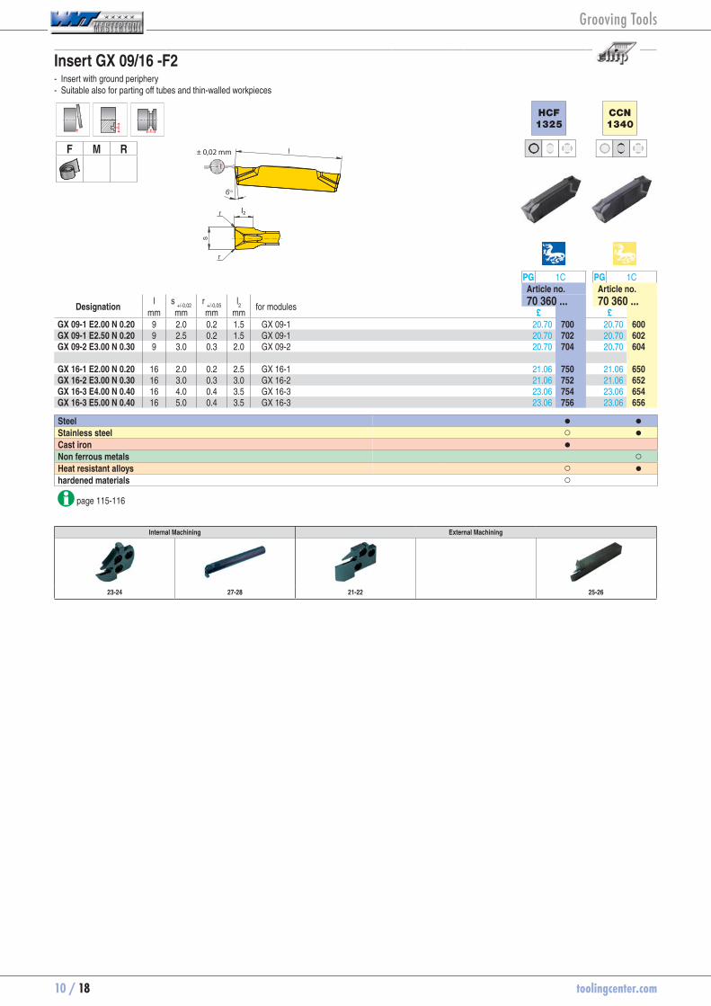
Insert GX 09/16 -F2 - Insert with ground periphery - Suitable also for parting off tubes and thin-walled workpieces
F M R
l2
± 0,02 mm
HCF
1325
CCN
1340
PG 1C PG 1CArticle no. Article no.
Designation l s
+/-0,02r
+/-0,05l2
for modules 70 360 ... 70 360 ...mm mm mm mm £ £
GX 09-1 E2.00 N 0.20 9 2.0 0.2 1.5 GX 09-1 20.70 70360700 20.70 70360600GX 09-1 E2.50 N 0.20 9 2.5 0.2 1.5 GX 09-1 20.70 70360702 20.70 70360602GX 09-2 E3.00 N 0.30 9 3.0 0.3 2.0 GX 09-2 20.70 70360704 20.70 70360604 GX 16-1 E2.00 N 0.20 16 2.0 0.2 2.5 GX 16-1 21.06 70360750 21.06 70360650GX 16-2 E3.00 N 0.30 16 3.0 0.3 3.0 GX 16-2 21.06 70360752 21.06 70360652GX 16-3 E4.00 N 0.40 16 4.0 0.4 3.5 GX 16-3 23.06 70360754 23.06 70360654GX 16-3 E5.00 N 0.40 16 5.0 0.4 3.5 GX 16-3 23.06 70360756 23.06 70360656
Steel ● ●Stainless steel ○ ●Cast iron ● Non ferrous metals ○Heat resistant alloys ○ ●hardened materials ○
page 115-116
Internal Machining External Machining
23-24 27-28 21-22 25-26
Grooving Tools

toolingcenter.com 10 / 19
10
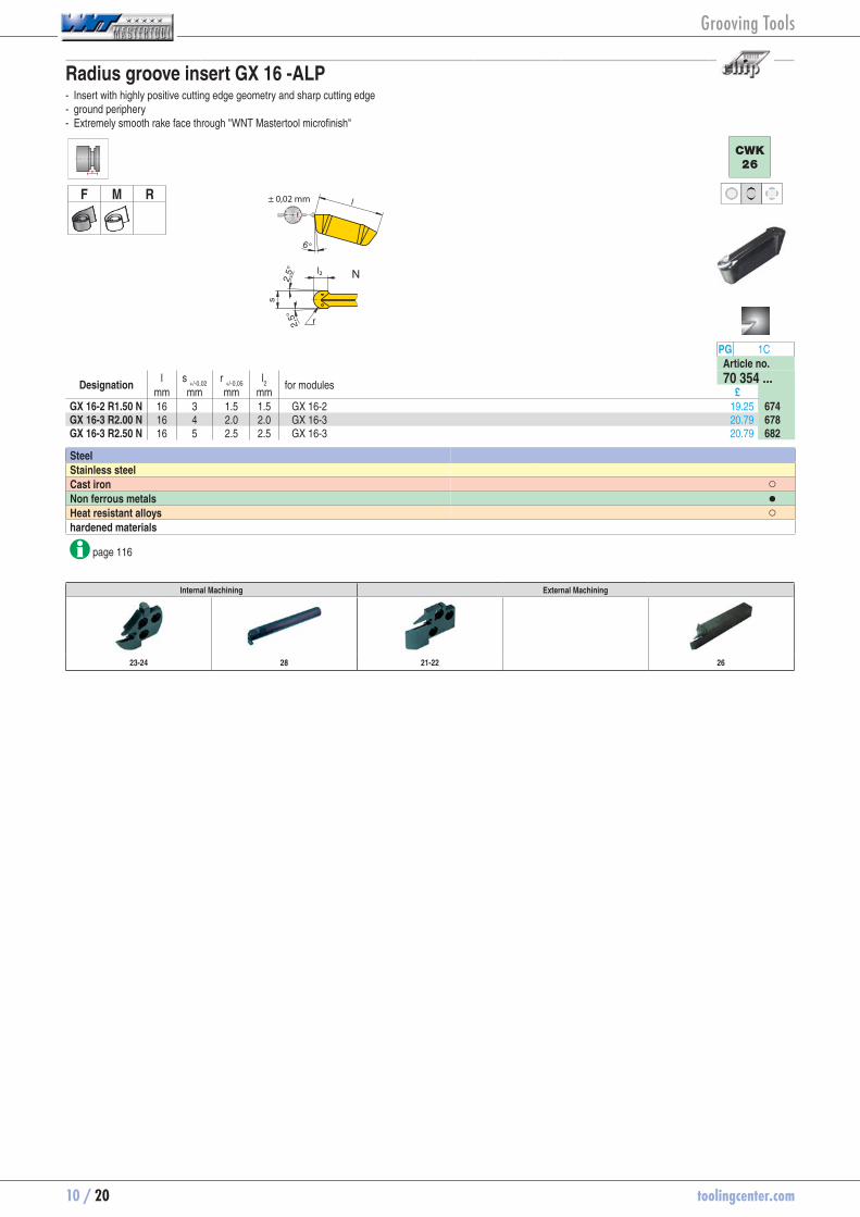
Insert GX 16 -ALP - Insert with highly positive cutting edge geometry and sharp cutting edge - ground periphery - Extremely smooth rake face through "WNT Mastertool microfinish"
F M R± 0,02 mm
l2
CWK
26
PG 1CArticle no.
Designation l s
+/-0,02r
+/-0,05l2
for modules 70 350 ...mm mm mm mm £
GX 16-1 E2.00 N 0.20 16 2 0.2 2.5 GX 16-1 15.98 70350650GX 16-2 E3.00 N 0.30 16 3 0.3 3.0 GX 16-2 15.98 70350658GX 16-3 E4.00 N 0.40 16 4 0.4 3.5 GX 16-3 17.43 70350670GX 16-4 E6.00 N 0.50 16 6 0.5 4.0 GX 16-4 18.34 70350678
Steel Stainless steel Cast iron ○Non ferrous metals ●Heat resistant alloys ○hardened materials
page 116
Internal Machining External Machining
23-24 28 21-22 26
Grooving Tools
10 / 20 toolingcenter.com
Radius groove insert GX 16 -ALP - Insert with highly positive cutting edge geometry and sharp cutting edge - ground periphery - Extremely smooth rake face through "WNT Mastertool microfinish"
F M R ± 0,02 mm
l2
CWK
26
PG 1CArticle no.
Designation l s
+/-0,02r
+/-0,05l2
for modules 70 354 ...mm mm mm mm £
GX 16-2 R1.50 N 16 3 1.5 1.5 GX 16-2 19.25 70354674GX 16-3 R2.00 N 16 4 2.0 2.0 GX 16-3 20.79 70354678GX 16-3 R2.50 N 16 5 2.5 2.5 GX 16-3 20.79 70354682
Steel Stainless steel Cast iron ○Non ferrous metals ●Heat resistant alloys ○hardened materials
page 116
Internal Machining External Machining
23-24 28 21-22 26
Grooving Tools
toolingcenter.com 10 / 21
10
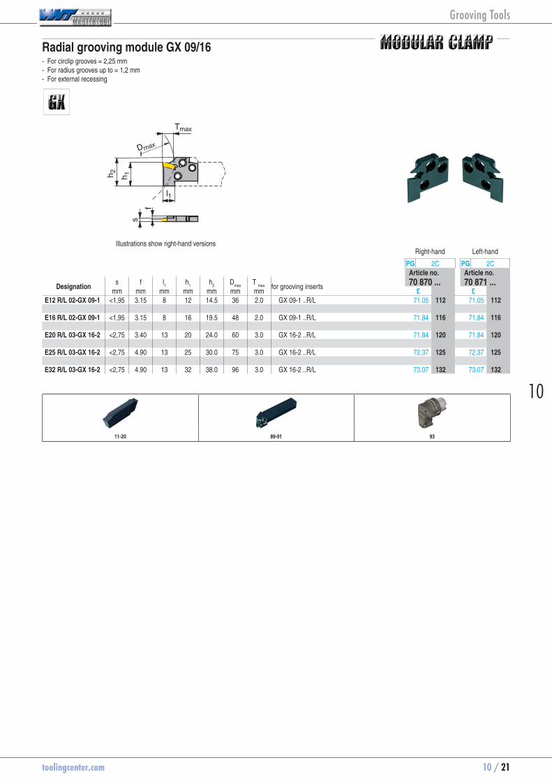
Radial grooving module GX 09/16 - For circlip grooves = 2,25 mm - For radius grooves up to = 1,2 mm - For external recessing
l1
h 1h 2
Tmaxs
fDmax
Illustrations show right-hand versionsRight-hand Left-hand
PG 2C PG 2CArticle no. Article no.
Designation s f l
1 h
1 h
2 D
max T
max.
for grooving inserts 70 870 ... 70 871 ...mm mm mm mm mm mm mm £ £
E12 R/L 02-GX 09-1 <1,95 3.15 8 12 14.5 36 2.0 GX 09-1 ..R/L 71.05 70870112 71.05 70871112 E16 R/L 02-GX 09-1 <1,95 3.15 8 16 19.5 48 2.0 GX 09-1 ..R/L 71.84 70870116 71.84 70871116 E20 R/L 03-GX 16-2 <2,75 3.40 13 20 24.0 60 3.0 GX 16-2 ..R/L 71.84 70870120 71.84 70871120 E25 R/L 03-GX 16-2 <2,75 4.90 13 25 30.0 75 3.0 GX 16-2 ..R/L 72.37 70870125 72.37 70871125 E32 R/L 03-GX 16-2 <2,75 4.90 13 32 38.0 96 3.0 GX 16-2 ..R/L 73.07 70870132 73.07 70871132
11-20 89-91 93
Grooving Tools

10 / 22 toolingcenter.com
Radial grooving module GX 09/16 - For grooving and turning - For circlip grooves = 5,25 mm - For radius grooves up to = 2,5 mm - For external recessing
l1
h 1h 2
Tmaxs
fDmax
Illustrations show right-hand versionsRight-hand Left-hand
PG 2C PG 2CArticle no. Article no.
Designation s f l
1 h
1 h
2 D
max T
max.
for grooving inserts 70 865 ... 70 866 ...mm mm mm mm mm mm mm £ £
E12 R/L 07-GX 09-1 2,00-2,75 3.15 8 12 14.5 36 7.0 GX 09-1 ..N 71.05 70865012 71.05 70866012E12 R/L 07-GX 09-2 2,76-3,75 2.80 8 12 14.5 36 7.0 GX 09-2 ..N 71.05 70865112 71.05 70866112 E16 R/L 07-GX 09-1 2,00-2,75 3.15 8 16 19.5 48 7.0 GX 09-1 ..N 71.84 70865016 71.84 70866016E16 R/L 07-GX 09-2 2,76-3,75 2.80 8 16 19.5 48 7.0 GX 09-2 ..N 71.84 70865116 71.84 70866116 E20 R/L 12-GX 16-1 2,00-2,75 3.75 13 20 24.0 60 12.0 GX 16-1 ..N 71.84 70865020 71.84 70866020E20 R/L 12-GX 16-2 2,76-3,75 3.40 13 20 24.0 60 12.0 GX 16-2 ..N 71.84 70865120 71.84 70866120E20 R/L 12-GX 16-3 3,76-5,00 2.93 13 20 24.0 60 12.0 GX 16-3 ..N 71.84 70865220 71.84 70866220 E25 R/L 12-GX 16-1 2,00-2,75 5.25 13 25 30.0 75 12.0 GX 16-1 ..N 72.37 70865025 72.37 70866025E25 R/L 12-GX 16-2 2,76-3,75 4.90 13 25 30.0 75 12.0 GX 16-2 ..N 72.37 70865125 72.37 70866125E25 R/L 12-GX 16-3 3,76-5,00 4.43 13 25 30.0 75 12.0 GX 16-3 ..N 72.37 70865225 72.37 70866225E25 R/L 12-GX 16-4 5,01-6,50 3.80 13 25 30.0 75 12.0 GX 16-4 ..N 72.37 70865325 72.37 70866325 E32 R/L 12-GX 16-2 2,76-3,75 4.90 13 32 38.0 96 12.0 GX 16-2 ..N 73.07 70865132 73.07 70866132E32 R/L 12-GX 16-3 3,76-5,00 4.43 13 32 38.0 96 12.0 GX 16-3 ..N 73.07 70865232 73.07 70866232E32 R/L 12-GX 16-4 5,01-6,50 3.80 13 32 38.0 96 12.0 GX 16-4 ..N 73.07 70865332 73.07 70866332
11-20 89-91 93
Grooving Tools
toolingcenter.com 10 / 23
10
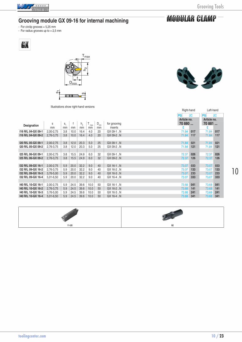
Grooving module GX 09-16 for internal machining - For circlip grooves = 5,25 mm - For radius grooves up to = 2,5 mm
h 2
Tmax
ss 1
fDmin
Illustrations show right-hand versionsRight-hand Left-hand
PG 2C PG 2CArticle no. Article no.
Designation s s
1 f h
2 T
max. D
min for grooving
inserts 70 880 ... 70 881 ...
mm mm mm mm mm mm £ £I16 R/L 04-GX 09-1 2,00-2,75 3.8 10.0 16.4 4.0 20 GX 09-1 ..N 71.84 70880017 71.84 70881017I16 R/L 04-GX 09-2 2,76-3,75 3.8 10.0 16.4 4.0 20 GX 09-2 ..N 71.84 70880117 71.84 70881117 I20 R/L 05-GX 09-1 2,00-2,75 3.8 12.0 20.3 5.0 25 GX 09-1 ..N 71.84 70880021 71.84 70881021I20 R/L 05-GX 09-2 2,76-3,75 3.8 12.0 20.3 5.0 25 GX 09-2 ..N 71.84 70880121 71.84 70881121 I25 R/L 06-GX 09-1 2,00-2,75 3.8 15.5 24.9 6.0 32 GX 09-1 ..N 72.37 70880026 72.37 70881026I25 R/L 06-GX 09-2 2,76-3,75 3.8 15.5 24.9 6.0 32 GX 09-2 ..N 72.37 70880126 72.37 70881126 I32 R/L 09-GX 16-1 2,00-2,75 5.9 20.0 32.2 9.0 40 GX 16-1 ..N 73.07 70880033 73.07 70881033I32 R/L 09-GX 16-2 2,76-3,75 5.9 20.0 32.2 9.0 40 GX 16-2 ..N 73.07 70880133 73.07 70881133I32 R/L 09-GX 16-3 3,76-5,00 5.9 20.0 32.2 9.0 40 GX 16-3 ..N 73.07 70880233 73.07 70881233I32 R/L 09-GX 16-4 5,01-6,50 5.9 20.0 32.2 9.0 40 GX 16-4 ..N 73.07 70880333 73.07 70881333 I40 R/L 10-GX 16-1 2,00-2,75 5.9 24.5 39.6 10.0 50 GX 16-1 ..N 73.68 70880041 73.68 70881041I40 R/L 10-GX 16-2 2,76-3,75 5.9 24.5 39.6 10.0 50 GX 16-2 ..N 73.68 70880141 73.68 70881141I40 R/L 10-GX 16-3 3,76-5,00 5.9 24.5 39.6 10.0 50 GX 16-3 ..N 73.68 70880241 73.68 70881241I40 R/L 10-GX 16-4 5,01-6,50 5.9 24.5 39.6 10.0 50 GX 16-4 ..N 73.68 70880341 73.68 70881341
11-20 92
Grooving Tools

10 / 24 toolingcenter.com
Grooving module GX 09/16 for internal machining - For circlip grooves = 2,25 mm - For radius grooves up to = 1,2 mm
h 2
Tmax
ss 1
fDmin
Illustrations show right-hand versionsRight-hand Left-hand
PG 2C PG 2CArticle no. Article no.
Designation s s
1 f h
2 T
max. D
min
for grooving inserts 70 885 ... 70 886 ...mm mm mm mm mm mm £ £
I16 R/L 02-GX 09-1 <1,95 3.8 10.0 16.4 2.0 20 GX 09-1 ..R/L 71.84 70885016 71.84 70886016 I20 R/L 02-GX 09-1 <1,95 3.8 12.0 20.3 2.0 25 GX 09-1 ..R/L 71.84 70885020 71.84 70886020 I25 R/L 02-GX 09-1 <1,95 3.8 15.5 24.9 2.0 32 GX 09-1 ..R/L 72.37 70885025 72.37 70886025 I32 R/L 03-GX 16-2 <2,75 5.9 20.0 32.2 3.0 40 GX 16-2 ..R/L 73.07 70885032 73.07 70886032 I40 R/L 03-GX 16-2 <2,75 5.9 24.5 39.6 3.0 50 GX 16-2 ..R/L 73.68 70885040 73.68 70886040
Right hand module → left hand insert only Left hand module → right hand insert only
11-20 92
Grooving Tools

toolingcenter.com 10 / 25
10
Monobloc tool holder GX 09
h 2f
h 1
l1
l3
hb
Tmaxs
Dmax
Illustrations show right-hand versionsRight-hand Left-hand
PG 2C PG 2CArticle no. Article no.
Designation h = h
1 b s f h
2 l
1 l
3 D
max T
max. for grooving
inserts 70 862 ... 70 863 ...
mm mm mm mm mm mm mm mm mm £ £E10 R/L 00-1010M 10 10 2,00-3,50 9.35 12 150 18 30 7.0 GX 09 .. 103.33 70862010 103.33 70863010
When using ‚R‘ or ‚L‘ tools the insert support seat requires modification to prevent the insert fouling
PG 2A PG 2A
Key D Clamping screw
Article no. Article no.Spare parts 70 950 ... 70 950 ...for grooving inserts £ £GX 09 .. T15 10.17 70950102 M4 x 11 8.65 70950442
11-18
Grooving Tools

10 / 26 toolingcenter.com
Monobloc tool holder GX 16
l1
h 1h 2Tmax
l5
hb
l3
sf
h 3
Illustrations show right-hand versionsRight-hand Left-hand
PG 2C PG 2CArticle no. Article no.
Designation h = h
1 b s f h
2 l
1 l
3 l
5 h
3 T
max. for grooving
inserts 70 888 ... 70 889 ...
mm mm mm mm mm mm mm mm mm mm £ £E12 R/L 0012-1212K-GX16-1 12 12 2,00-2,75 11.35 17 125 26 24 4 12.0 GX 16-1 76.23 70888212 76.23 70889212E12 R/L 0012-1212K-GX16-2 12 12 2,76-3,75 11.00 17 125 26 24 4 12.0 GX 16-2 76.23 70888312 76.23 70889312 E16 R/L 0012-1616K-GX16-1 16 16 2,00-2,75 15.35 21 125 26 24 4 12.0 GX 16-1 81.40 70888216 81.40 70889216E16 R/L 0012-1616K-GX16-2 16 16 2,76-3,75 15.00 21 125 26 24 4 12.0 GX 16-2 81.40 70888316 81.40 70889316E16 R/L 0012-1616K-GX16-3 16 16 3,76-5,00 14.53 21 125 26 24 4 12.0 GX 16-3 81.40 70888416 81.40 70889416 E20 R/L 0012-2020K-GX16-1 20 20 2,00-2,75 19.35 25 125 26 12.0 GX 16-1 93.68 70888220 93.68 70889220E20 R/L 0012-2020K-GX16-2 20 20 2,76-3,75 19.00 25 125 26 12.0 GX 16-2 93.68 70888320 93.68 70889320E20 R/L 0012-2020K-GX16-3 20 20 3,76-5,00 18.53 25 125 26 12.0 GX 16-3 93.68 70888420 93.68 70889420 E25 R/L 0012-2525M-GX16-2 25 25 2,76-3,75 24.00 30 150 26 12.0 GX 16-2 99.56 70888325 99.56 70889325E25 R/L 0012-2525M-GX16-3 25 25 3,76-5,00 23.53 30 150 26 12.0 GX 16-3 99.56 70888425 99.56 70889425
PG 2A PG 2A
Key-T Clamping screw
Article no. Article no.Spare parts 70 950 ... 70 950 ...for grooving inserts £ £GX 16-1 T15 5.36 70950738 M3,5 x 14 3.42 70950160GX 16-2 T15 5.36 70950738 M3,5 x 14 3.42 70950160GX 16-3 T15 5.36 70950738 M3,5 x 14 3.42 70950160
11-20
Grooving Tools

toolingcenter.com 10 / 27
10
Mono-boring bars - GX 09
l1
T max
Dmin
l2
d 1
h
f
Illustrations show right-hand versionsRight-hand Left-hand
PG 2C PG 2CArticle no. Article no.
Designation f d
1 h l
1 l
2 T
max. D
min for grooving
inserts 70 858 ... 70 859 ...
mm mm mm mm mm mm mm £ £I12 R/L 90-2,5D-GX09 11 16 15.25 150 30 3.0 16 GX 09 .. 126.67 70858012 126.67 70859012
Right hand boring bar→ left hand insert only Left hand boring bar→ right hand insert only When using „R“ or „L“ tools the insert support seat
requires modification to prevent the insert fouling.
PG 2A PG 2A
Key D Clamping screw
Article no. Article no.Spare parts 70 950 ... 70 950 ...for grooving inserts £ £GX 09 .. T15 10.17 70950102 M3,5 x 12,5 7.51 70950441
11-18
Grooving Tools

10 / 28 toolingcenter.com
Monobloc boring bars GX 16
Dmin d 1
Tmax
l1
l2
f
hs
Illustrations show right-hand versionsRight-hand Left-hand
PG 2C PG 2CArticle no. Article no.
Designation h d
1 D
min s
mmT
max. f l
1 l
2 for grooving
inserts 70 892 ... 70 893 ...
mm mm mm mm mm mm mm £ £I16 R/L 90-2.0D-GX16-1 15.25 16 20.5 2,00-2,75 5.5 13.5 150 32 GX 16-1 111.49 70892516 111.49 70893516I16 R/L 90-2.0D-GX16-2 15.25 16 20.5 2,76-3,75 5.5 13.5 150 32 GX 16-2 111.49 70892616 111.49 70893616 I20 R/L 90-2.0D-GX16-2 19.00 20 25.0 2,76-3,75 5.5 15.5 180 40 GX 16-2 120.44 70892620 120.44 70893620 I25 R/L 90-2.0D-GX16-2 24.00 25 32.0 2,76-3,75 8.0 20.5 200 50 GX 16-2 140.09 70892625 140.09 70893625I25 R/L 90-2.0D-GX16-3 24.00 25 32.0 3,76-5,00 10.0 22.5 200 50 GX 16-3 140.09 70892725 140.09 70893725 I32 R/L 90-2.0D-GX16-2 31.00 32 42.0 2,76-3,75 11.0 27.5 250 64 GX 16-2 162.81 70892632 162.81 70893632I32 R/L 90-2.0D-GX16-3 31.00 32 42.0 3,76-5,00 11.0 27.5 250 64 GX 16-3 162.81 70892732 162.81 70893732
PG 2A PG 2A
Key-T Clamping screw
Article no. Article no.Spare parts 70 950 ... 70 950 ...for grooving inserts £ £GX 16-1 T15 5.36 70950738 M4 x 14 7.18 70950403GX 16-2 T15 5.36 70950738 M4 x 14 7.18 70950403GX 16-3 T15 5.36 70950738 M4 x 14 7.18 70950403
11-20
Grooving Tools

toolingcenter.com 10 / 29
10
Insert GX 24 -E
F M R ± 0,18 mm
l2
HCF
1325
HCR
1335
CCN
1340
CWX
25
PG 1C PG 1C PG 1C PG 1CArticle no. Article no. Article no. Article no.
Designation l s
+/-0,05r
+/-0,05l2
for modules 70 350 ... 70 350 ... 70 350 ... 70 350 ...mm mm mm mm £ £ £ £
GX 24-2 E3.00 N 0.30 24 3 0.3 2.5 GX 24-2 14.61 70350732 14.61 70350532 14.61 70350632 13.98 70350232GX 24-3 E4.00 N 0.40 24 4 0.4 3.0 GX 24-3 15.98 70350736 15.98 70350536 15.98 70350636 15.16 70350236GX 24-3 E5.00 N 0.40 24 5 0.4 3.0 GX 24-3 17.43 70350740 17.43 70350540 17.43 70350640 16.70 70350240GX 24-4 E6.00 N 0.50 24 6 0.5 3.5 GX 24-4 19.16 70350744 19.16 70350544 19.16 70350644 18.07 70350244
Steel ● ● ● ●Stainless steel ○ ○ ● ○Cast iron ● ● ●Non ferrous metals ○ Heat resistant alloys ○ ● ○hardened materials ○ ○
page 115-116
Internal Machining External Machining
38 42 36-39 40 41
Grooving Tools

10 / 30 toolingcenter.com
Insert GX 24 -M1 - Very good swarf control
F M R
l2
± 0,15 mm
HCF
1325
HCN
1345
CCN
1340
PG 1C PG 1C PG 1CArticle no. Article no. Article no.
Designation l s
+/-0,05r
+/-0,05l2
for modules 70 363 ... 70 363 ... 70 363 ...mm mm mm mm £ £ £
GX 24-1 E2.00 N 0.20 24 2 0.2 2.5 GX 24-1 14.61 70363700 14.61 70363800 14.61 70363600GX 24-2 E3.00 N 0.20 24 3 0.2 2.5 GX 24-2 14.61 70363702 14.61 70363802 14.61 70363602GX 24-3 E4.00 N 0.30 24 4 0.3 3.0 GX 24-3 15.98 70363704 15.98 70363804 15.98 70363604
Steel ● ● ●Stainless steel ○ ● ●Cast iron ● Non ferrous metals ○Heat resistant alloys ○ ○ ●hardened materials ○
page 115-116
Internal Machining External Machining
38 42 36-39 40 41
Grooving Tools

toolingcenter.com 10 / 31
10
Radius groove insert GX 24 -M3
F M R± 0,18 mm
l2
HCF
1325
HCR
1335
CWX
25
PG 1C PG 1C PG 1CArticle no. Article no. Article no.
Designation l s
+/-0,02r
+/-0,05l2
for modules 70 354 ... 70 354 ... 70 354 ...mm mm mm mm £ £ £
GX 24-2 R1.50 N 24 3 1.5 1.5 GX 24-2 19.43 70354752 19.43 70354552 18.52 70354252GX 24-3 R2.00 N 24 4 2.0 2.5 GX 24-3 20.79 70354754 20.79 70354554 19.79 70354254GX 24-3 R2.50 N 24 5 2.5 3.0 GX 24-3 21.70 70354756 21.70 70354556 20.70 70354256GX 24-4 R3.00 N 24 6 3.0 3.5 GX 24-4 23.33 70354758 23.33 70354558 22.33 70354258
Steel ● ● ●Stainless steel ○ ○ ○Cast iron ● ● ●Non ferrous metals Heat resistant alloys ○ ○hardened materials ○ ○
page 116
Internal Machining External Machining
38 42 36-39 40 41
Grooving Tools
10 / 32 toolingcenter.com
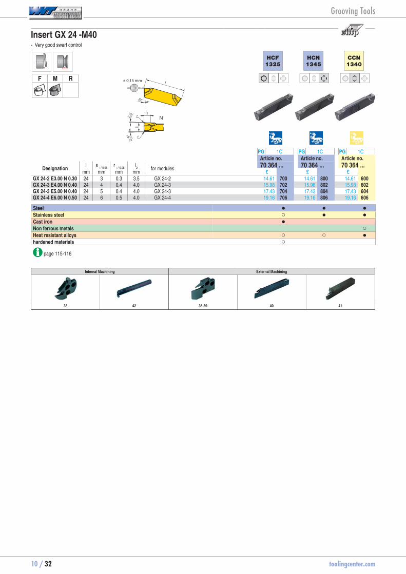
Insert GX 24 -M40 - Very good swarf control
F M R
l2
± 0,15 mm
HCF
1325
HCN
1345
CCN
1340
PG 1C PG 1C PG 1CArticle no. Article no. Article no.
Designation l s
+/-0,05r
+/-0,05l2
for modules 70 364 ... 70 364 ... 70 364 ...mm mm mm mm £ £ £
GX 24-2 E3.00 N 0.30 24 3 0.3 3.5 GX 24-2 14.61 70364700 14.61 70364800 14.61 70364600GX 24-3 E4.00 N 0.40 24 4 0.4 4.0 GX 24-3 15.98 70364702 15.98 70364802 15.98 70364602GX 24-3 E5.00 N 0.40 24 5 0.4 4.0 GX 24-3 17.43 70364704 17.43 70364804 17.43 70364604GX 24-4 E6.00 N 0.50 24 6 0.5 4.0 GX 24-4 19.16 70364706 19.16 70364806 19.16 70364606
Steel ● ● ●Stainless steel ○ ● ●Cast iron ● Non ferrous metals ○Heat resistant alloys ○ ○ ●hardened materials ○
page 115-116
Internal Machining External Machining
38 42 36-39 40 41
Grooving Tools
toolingcenter.com 10 / 33
10
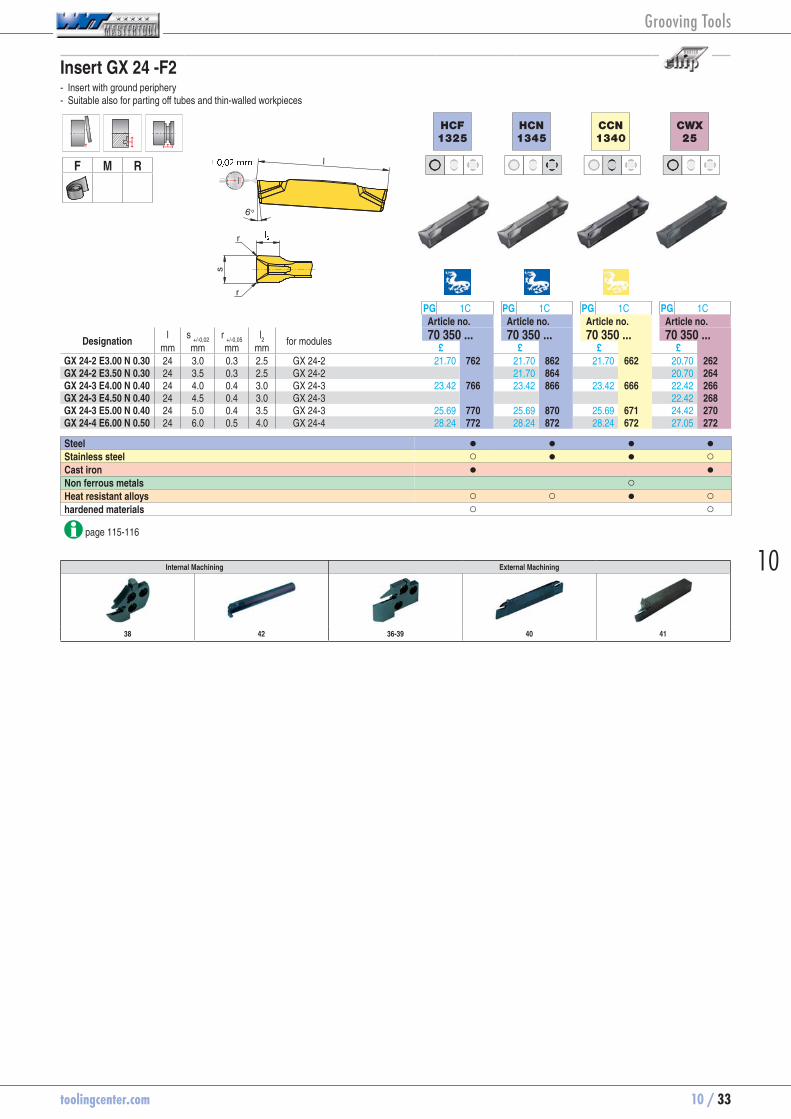
Insert GX 24 -F2 - Insert with ground periphery - Suitable also for parting off tubes and thin-walled workpieces
F M R
HCF
1325
HCN
1345
CCN
1340
CWX
25
PG 1C PG 1C PG 1C PG 1CArticle no. Article no. Article no. Article no.
Designation l s
+/-0,02r
+/-0,05l2
for modules 70 350 ... 70 350 ... 70 350 ... 70 350 ...mm mm mm mm £ £ £ £
GX 24-2 E3.00 N 0.30 24 3.0 0.3 2.5 GX 24-2 21.70 70350762 21.70 70350862 21.70 70350662 20.70 70350262GX 24-2 E3.50 N 0.30 24 3.5 0.3 2.5 GX 24-2 21.70 70350864 20.70 70350264GX 24-3 E4.00 N 0.40 24 4.0 0.4 3.0 GX 24-3 23.42 70350766 23.42 70350866 23.42 70350666 22.42 70350266GX 24-3 E4.50 N 0.40 24 4.5 0.4 3.0 GX 24-3 22.42 70350268GX 24-3 E5.00 N 0.40 24 5.0 0.4 3.5 GX 24-3 25.69 70350770 25.69 70350870 25.69 70350671 24.42 70350270GX 24-4 E6.00 N 0.50 24 6.0 0.5 4.0 GX 24-4 28.24 70350772 28.24 70350872 28.24 70350672 27.05 70350272
Steel ● ● ● ●Stainless steel ○ ● ● ○Cast iron ● ●Non ferrous metals ○ Heat resistant alloys ○ ○ ● ○hardened materials ○ ○
page 115-116
Internal Machining External Machining
38 42 36-39 40 41
Grooving Tools
10 / 34 toolingcenter.com
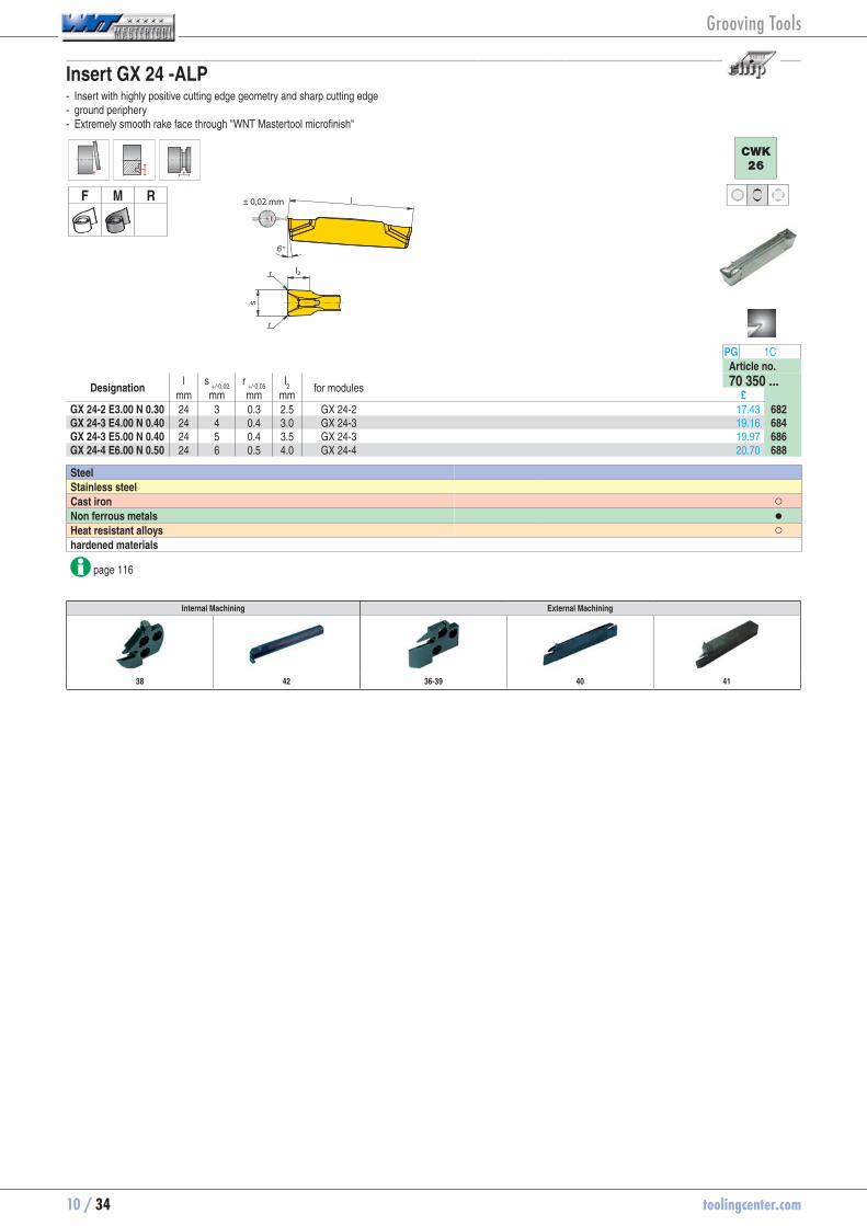
Insert GX 24 -ALP - Insert with highly positive cutting edge geometry and sharp cutting edge - ground periphery - Extremely smooth rake face through "WNT Mastertool microfinish"
F M R
l2
± 0,02 mm
CWK
26
PG 1CArticle no.
Designation l s
+/-0,02r
+/-0,05l2
for modules 70 350 ...mm mm mm mm £
GX 24-2 E3.00 N 0.30 24 3 0.3 2.5 GX 24-2 17.43 70350682GX 24-3 E4.00 N 0.40 24 4 0.4 3.0 GX 24-3 19.16 70350684GX 24-3 E5.00 N 0.40 24 5 0.4 3.5 GX 24-3 19.97 70350686GX 24-4 E6.00 N 0.50 24 6 0.5 4.0 GX 24-4 20.70 70350688
Steel Stainless steel Cast iron ○Non ferrous metals ●Heat resistant alloys ○hardened materials
page 116
Internal Machining External Machining
38 42 36-39 40 41
Grooving Tools
toolingcenter.com 10 / 35
10
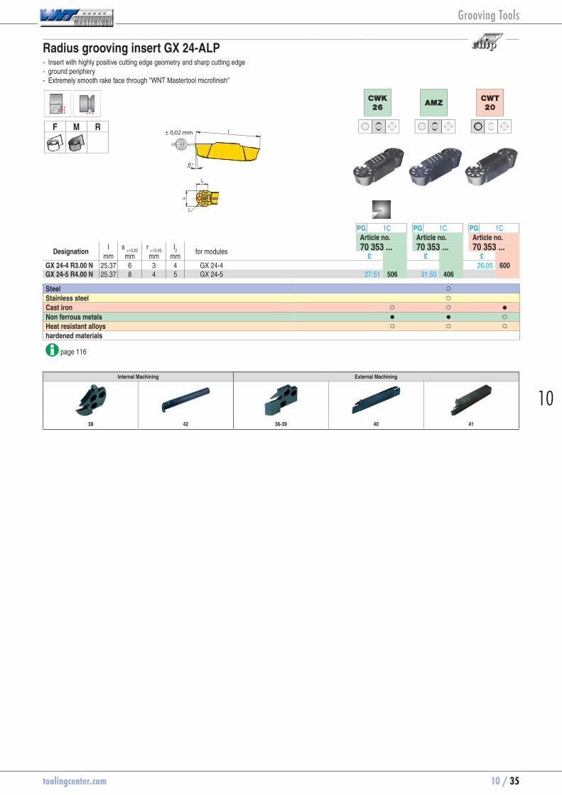
Radius grooving insert GX 24-ALP - Insert with highly positive cutting edge geometry and sharp cutting edge - ground periphery - Extremely smooth rake face through "WNT Mastertool microfinish"
F M R± 0,02 mm
l2
CWK
26AMZ
CWT
20
PG 1C PG 1C PG 1CArticle no. Article no. Article no.
Designation l s
+/-0,02r
+/-0,05l2
for modules 70 353 ... 70 353 ... 70 353 ...mm mm mm mm £ £ £
GX 24-4 R3.00 N 25.37 6 3 4 GX 24-4 26.05 70353600GX 24-5 R4.00 N 25.37 8 4 5 GX 24-5 27.51 70353506 31.50 70353406
Steel ○ Stainless steel ○ Cast iron ○ ○ ●Non ferrous metals ● ● ○Heat resistant alloys ○ ○ ○hardened materials
page 116
Internal Machining External Machining
38 42 36-39 40 41
Grooving Tools

10 / 36 toolingcenter.com
Axial grooving module GX 24 short - For axial grooving - For face turning
D
Illustrations show right-hand versionsRight-hand Left-hand
PG 2C PG 2CArticle no. Article no.
Designation D s f l
1 h
1 h
2 T
max. for grooving
inserts 70 890 ... 70 891 ...
mm mm mm mm mm mm mm £ £E20 R/L 14-GX 24-2 A 50-70 3 3.40 22 20 24 14.0 GX 24-2 93.33 70890100 93.33 70891100E20 R/L 14-GX 24-2 A 70-100 3 3.40 22 20 24 14.0 GX 24-2 93.33 70890102 93.33 70891102E20 R/L 14-GX 24-2 A 100-150 3 3.40 22 20 24 14.0 GX 24-2 93.33 70890104 93.33 70891104 E25 R/L 15-GX 24-2 A 50-70 3 4.90 22 25 30 15.0 GX 24-2 94.12 70890200 94.12 70891200E25 R/L 15-GX 24-2 A 70-100 3 4.90 22 25 30 15.0 GX 24-2 94.12 70890202 94.12 70891202E25 R/L 15-GX 24-2 A 100-150 3 4.90 22 25 30 15.0 GX 24-2 94.12 70890204 94.12 70891204E25 R/L 15-GX 24-3 A 50-70 4/5 4.43 22 25 30 15.0 GX 24-3 94.12 70890206 94.12 70891206E25 R/L 15-GX 24-3 A 70-100 4/5 4.43 22 25 30 15.0 GX 24-3 94.12 70890208 94.12 70891208E25 R/L 15-GX 24-3 A 100-150 4/5 4.43 22 25 30 15.0 GX 24-3 94.12 70890210 94.12 70891210E25 R/L 15-GX 24-3 A 150-300 4/5 4.43 22 25 30 15.0 GX 24-3 94.12 70890212 94.12 70891212E25 R/L 15-GX 24-4 A 50-70 6 3.80 22 25 30 15.0 GX 24-4 94.12 70890214 94.12 70891214E25 R/L 15-GX 24-4 A 70-100 6 3.80 22 25 30 15.0 GX 24-4 94.12 70890216 94.12 70891216E25 R/L 15-GX 24-4 A 100-150 6 3.80 22 25 30 15.0 GX 24-4 94.12 70890218 94.12 70891218E25 R/L 15-GX 24-4 A 150-300 6 3.80 22 25 30 15.0 GX 24-4 94.12 70890220 94.12 70891220 E32 R/L 15-GX 24-3 A 70-100 4/5 4.43 22 32 38 15.0 GX 24-3 94.82 70890300 94.82 70891300E32 R/L 15-GX 24-3 A 100-150 4/5 4.43 22 32 38 15.0 GX 24-3 94.82 70890302 94.82 70891302E32 R/L 15-GX 24-3 A 150-300 4/5 4.43 22 32 38 15.0 GX 24-3 94.82 70890304 94.82 70891304E32 R/L 15-GX 24-4 A 70-100 6 3.80 22 32 38 15.0 GX 24-4 94.82 70890306 94.82 70891306E32 R/L 15-GX 24-4 A 100-150 6 3.80 22 32 38 15.0 GX 24-4 94.82 70890308 94.82 70891308E32 R/L 15-GX 24-4 A 150-300 6 3.80 22 32 38 15.0 GX 24-4 94.82 70890310 94.82 70891310E32 R/L 15-GX 24-4 A 300-900 6 3.80 22 32 38 15.0 GX 24-4 94.82 70890312 94.82 70891312
29-35 89-91 93
Grooving Tools
toolingcenter.com 10 / 37
10
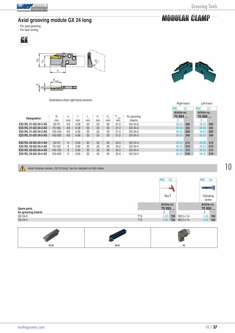
Axial grooving module GX 24 long - For axial grooving - For face turning
D
Illustrations show right-hand versionsRight-hand Left-hand
PG 2C PG 2CArticle no. Article no.
Designation D s f l
1 h
1 h
2 T
max. for grooving
inserts 70 894 ... 70 895 ...
mm mm mm mm mm mm mm £ £E25 R/L 21-GX 24-3 AS 50-70 4/5 4.58 35 25 30 21.0 GX 24-3 96.05 70894200 96.05 70895200E25 R/L 21-GX 24-3 AS 70-100 4/5 4.58 35 25 30 21.0 GX 24-3 96.05 70894202 96.05 70895202E25 R/L 21-GX 24-3 AS 100-150 4/5 4.58 35 25 30 21.0 GX 24-3 96.05 70894204 96.05 70895204E25 R/L 21-GX 24-3 AS 150-300 4/5 4.58 35 25 30 21.0 GX 24-3 96.05 70894206 96.05 70895206 E25 R/L 25-GX 24-4 AS 50-70 6 3.95 35 25 30 25.0 GX 24-4 96.05 70894210 96.05 70895210E25 R/L 25-GX 24-4 AS 70-100 6 3.95 35 25 30 25.0 GX 24-4 96.05 70894212 96.05 70895212E25 R/L 25-GX 24-4 AS 100-150 6 3.95 35 25 30 25.0 GX 24-4 96.05 70894214 96.05 70895214E25 R/L 25-GX 24-4 AS 150-300 6 3.95 35 25 30 25.0 GX 24-4 96.05 70894216 96.05 70895216
Axial modules version „GX 24 long“ can be clamped on both sides.
PG 2A PG 2A
Key-T Clamping screw
Article no. Article no.Spare parts 70 950 ... 70 950 ...for grooving inserts £ £GX 24-3 T15 5.36 70950738 M3,5 x 14 3.42 70950160GX 24-4 T15 5.36 70950738 M3,5 x 14 3.42 70950160
29-35 89-91 93
Grooving Tools

10 / 38 toolingcenter.com
Grooving module GX 24 for internal machining - for grooving and turning
h 2
Tmax
ss 1
fDmin
Neutral
PG 2CArticle no.
Designation s s
1 f h
2 T
max. D
min for grooving
inserts 70 880 ...
mm mm mm mm mm mm £I40 N 19-GX 24-2 2,76-3,75 6.2 33.5 40.7 19.0 60 GX 24-2 ..N 83.68 70880340I40 N 19-GX 24-3 3,76-5,00 6.2 33.5 40.7 19.0 60 GX 24-3 ..N 83.68 70880440I40 N 19-GX 24-4 5,01-6,50 6.2 33.5 40.7 19.0 60 GX 24-4 ..N 83.68 70880540
29-35 92
Grooving Tools

toolingcenter.com 10 / 39
10
Radial grooving module GX 24 - For deep radial parting and grooving - For turning
l1
h 1h 2Tmax
s
fDmax
Illustrations show right-hand versionsRight-hand Left-hand
PG 2C PG 2CArticle no. Article no.
Designation s f l
1 h
1 h
2 D
max T
max. for grooving
inserts 70 867 ... 70 868 ...
mm mm mm mm mm mm mm £ £E20 R/L 21-GX 24-1 2,0-2,75 3.60 22 20 24 60 21.0 GX 24-1 71.84 70867020 71.84 70868020E20 R/L 21-GX 24-2 3 3.40 22 20 24 60 21.0 GX 24-2 71.84 70867120 71.84 70868120 E25 R/L 21-GX 24-1 2,0-2,75 5.10 22 25 30 75 21.0 GX 24-1 72.37 70867025 72.37 70868025E25 R/L 21-GX 24-2 3 4.90 22 25 30 75 21.0 GX 24-2 72.37 70867125 72.37 70868125E25 R/L 21-GX 24-3 4/5 4.43 22 25 30 75 21.0 GX 24-3 72.37 70867225 72.37 70868225E25 R/L 21-GX 24-4 6 3.80 22 25 30 75 21.0 GX 24-4 72.37 70867325 72.37 70868325E25 R/L 21-GX 24-5 8 2.95 22 25 30 75 21.0 GX 24-5 72.37 70867425 72.37 70868425 E32 R/L 21-GX 24-3 4/5 4.43 22 32 38 96 21.0 GX 24-3 73.07 70867232 73.07 70868232E32 R/L 21-GX 24-4 6 3.80 22 32 38 96 21.0 GX 24-4 73.07 70867332 73.07 70868332
12-35 89-91 93
Grooving Tools
10 / 40 toolingcenter.com
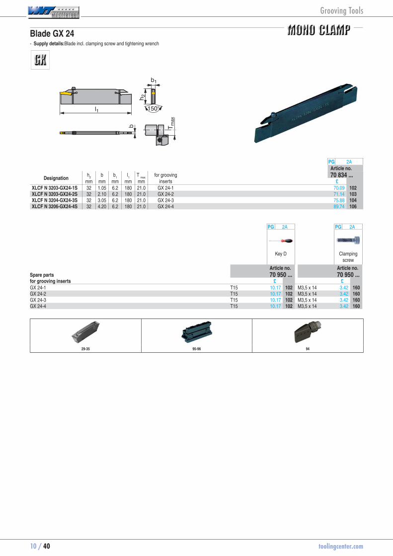
Blade GX 24 - Supply details:Blade incl. clamping screw and tightening wrench
h 2
l1
b T max
150°
b1
PG 2AArticle no.
Designation h
2 b b
1 l
1 T
max. for grooving
inserts 70 834 ...
mm mm mm mm mm £XLCF N 3203-GX24-1S 32 1.05 6.2 180 21.0 GX 24-1 70.09 70834102XLCF N 3203-GX24-2S 32 2.10 6.2 180 21.0 GX 24-2 71.14 70834103XLCF N 3204-GX24-3S 32 3.05 6.2 180 21.0 GX 24-3 75.88 70834104XLCF N 3206-GX24-4S 32 4.20 6.2 180 21.0 GX 24-4 89.74 70834106
PG 2A PG 2A
Key D Clamping screw
Article no. Article no.Spare parts 70 950 ... 70 950 ...for grooving inserts £ £GX 24-1 T15 10.17 70950102 M3,5 x 14 3.42 70950160GX 24-2 T15 10.17 70950102 M3,5 x 14 3.42 70950160GX 24-3 T15 10.17 70950102 M3,5 x 14 3.42 70950160GX 24-4 T15 10.17 70950102 M3,5 x 14 3.42 70950160
29-35 95-96 94
Grooving Tools

toolingcenter.com 10 / 41
10
Monobloc tool holder GX 24
l1
h 1h 2Tmax
l5
hb
l3
sf
h 3
Illustrations show right-hand versionsRight-hand Left-hand
PG 2C PG 2CArticle no. Article no.
Designation h = h
1 b s f h
2 l
1 l
3 l
5 h
3 T
max. for grooving
inserts 70 862 ... 70 863 ...
mm mm mm mm mm mm mm mm mm mm £ £E16 R/L 0021-1616K-GX24-1 16 16 2,00-2,75 15.20 21 125 35 32 4 21.0 GX 24-1 87.46 70862160 87.46 70863160E16 R/L 0021-1616K-GX24-2 16 16 2,76-3,75 15.00 21 125 35 32 4 21.0 GX 24-2 87.46 70862016 87.46 70863016 E20 R/L 0021-2020K-GX24-1 20 20 2,00-2,75 19.20 25 125 35 21.0 GX 24-1 100.70 70862200 100.70 70863200E20 R/L 0021-2020K-GX24-2 20 20 2,76-3,75 19.00 25 125 35 21.0 GX 24-2 100.70 70862020 100.70 70863020E20 R/L 0021-2020K-GX24-3 20 20 3,76-5,00 18.53 25 125 35 21.0 GX 24-3 100.70 70862120 100.70 70863120 E25 R/L 0021-2525M-GX24-2 25 25 2,76-3,75 24.00 30 150 35 21.0 GX 24-2 107.72 70862025 107.72 70863025E25 R/L 0021-2525M-GX24-3 25 25 3,76-5,00 23.53 30 150 35 21.0 GX 24-3 107.72 70862125 107.72 70863125E25 R/L 0021-2525M-GX24-4 25 25 5,01-6,50 22.90 30 150 35 21.0 GX 24-4 107.72 70862225 107.72 70863225 E32 R/L 0021-3225P-GX24-2 32 25 2,76-3,75 24.00 37 170 35 21.0 GX 24-2 115.00 70862032 115.00 70863032E32 R/L 0021-3225P-GX24-3 32 25 3,76-5,00 23.53 37 170 35 21.0 GX 24-3 115.00 70862132 115.00 70863132E32 R/L 0021-3225P-GX24-4 32 25 5,01-6,50 22.90 37 170 35 21.0 GX 24-4 115.00 70862232 115.00 70863232
PG 2A PG 2A
Key-T Clamping screw
Article no. Article no.Spare parts 70 950 ... 70 950 ...for grooving inserts £ £GX 24-1 T20 5.59 70950448 M4 x 18 3.98 70950204GX 24-2 T20 5.59 70950448 M4 x 18 3.98 70950204GX 24-3 T20 5.59 70950448 M4 x 18 3.98 70950204GX 24-4 T20 5.59 70950448 M4 x 18 3.98 70950204
29-35
Grooving Tools

10 / 42 toolingcenter.com
Monobloc boring bars GX 24
Dmin d 1
Tmax
l1
l2
f
hs
Illustrations show right-hand versionsRight-hand Left-hand
PG 2C PG 2CArticle no. Article no.
Designation h d
1 D
min s
mmT
max. f l
1 l
2 for grooving
inserts 70 894 ... 70 895 ...
mm mm mm mm mm mm mm £ £I32 R/L 90-2.0D-GX24-2 31.0 32 42 2,76-3,75 11.0 27.5 250 64 GX 24-2 162.81 70894132 162.81 70895132I32 R/L 90-2.0D-GX24-3 31.0 32 42 3,76-5,00 11.0 27.5 250 64 GX 24-3 162.81 70894232 162.81 70895232I32 R/L 90-2.0D-GX24-4 31.0 32 47 5,01-6,50 17.5 30.4 250 64 GX 24-4 162.81 70894332 162.81 70895332 I40 R/L 90-2.0D-GX24-3 38.5 40 53 3,76-5,00 12.0 32.5 300 80 GX 24-3 202.28 70894240 202.28 70895240I40 R/L 90-2.0D-GX24-4 38.5 40 57 5,01-6,50 17.5 34.4 300 80 GX 24-4 202.28 70894340 202.28 70895340
PG 2A PG 2A
Key-T Clamping screw
Article no. Article no.Spare parts 70 950 ... 70 950 ...for grooving inserts £ £GX 24-2 T20 5.59 70950448 M5 x 18 4.79 70950404GX 24-3 T20 5.59 70950448 M5 x 18 4.79 70950404GX 24-4 T20 5.59 70950448 M5 x 18 4.79 70950404
29-35
Grooving Tools

toolingcenter.com 10 / 43
10
Insert SX -M1 - Specially developed geometry with negative edge-chamfers available in right, left and neutral types
F M R
± 0,10 mm
HCF
1325
HCR
1335
HCN
1345
CCN
1340
PG 1C PG 1C PG 1C PG 1CArticle no. Article no. Article no. Article no.
Designation R/L/N s
+/-0,05 K° r
+/-0,05 for blades 70 342 ... 70 342 ... 70 342 ... 70 342 ...mm mm £ £ £ £
SX E2.00 L 6 L 2 6 0.2 -SX2 9.81 70342712 9.81 70342612SX E3.00 L 6 L 3 6 0.2 -SX3 10.44 70342713 10.44 70342613SX E4.00 L 6 L 4 6 0.3 -SX4 10.98 70342714 10.98 70342614 SX E2.00 N 0.20 N 2 0 0.2 -SX2 9.81 70342722 9.81 70342822 9.81 70342622SX E3.00 N 0.20 N 3 0 0.2 -SX3 10.44 70342723 10.44 70342523 10.44 70342823 10.44 70342623SX E4.00 N 0.30 N 4 0 0.3 -SX4 10.98 70342724 10.98 70342524 10.98 70342824 10.98 70342624SX E5.00 N 0.30 N 5 0 0.3 -SX5 11.71 70342725 11.71 70342625SX E6.00 N 0.40 N 6 0 0.4 -SX6 12.62 70342726 12.62 70342626 SX E2.00 R 6 R 2 6 0.2 -SX2 9.81 70342702 9.81 70342602SX E3.00 R 6 R 3 6 0.2 -SX3 10.44 70342703 10.44 70342603SX E4.00 R 6 R 4 6 0.3 -SX4 10.98 70342704 10.98 70342604
Steel ● ● ● ●Stainless steel ○ ○ ● ●Cast iron ● ● Non ferrous metals ○Heat resistant alloys ○ ○ ●hardened materials ○
page 115-116
Note: reduce feed rate by 20-50% with R/L version!
Internal Machining External Machining
48 49-50 51
Grooving Tools

10 / 44 toolingcenter.com
Insert SX -M2 - All purpose geometry for parting, grooving & turning.
F M R ± 0,10 mm
HCF
1325
HCR
1335
HCN
1345
CCN
1340
PG 1C PG 1C PG 1C PG 1CArticle no. Article no. Article no. Article no.
Designation s
+/-0,05r
+/-0,05 for blades 70 343 ... 70 343 ... 70 343 ... 70 343 ...mm mm £ £ £ £
SX E2.00 N 0.20 2 0.2 -SX2 9.81 70343722 9.81 70343522 9.81 70343822 9.81 70343622SX E3.00 N 0.30 3 0.3 -SX3 10.44 70343723 10.44 70343523 10.44 70343823 10.44 70343623SX E4.00 N 0.40 4 0.4 -SX4 10.98 70343724 10.98 70343524 10.98 70343824 10.98 70343624SX E5.00 N 0.40 5 0.4 -SX5 11.71 70343725 11.71 70343625SX E6.00 N 0.50 6 0.5 -SX6 12.62 70343726 12.62 70343626
Steel ● ● ● ●Stainless steel ○ ○ ● ●Cast iron ● ● Non ferrous metals ○Heat resistant alloys ○ ○ ●hardened materials ○
page 115-116
Internal Machining External Machining
48 49-50 51
Grooving Tools

toolingcenter.com 10 / 45
10
Insert SX -M3 - for grooving and copy turning - very good chip control
F M R
sr
am
ax
6°
± 0,10 mm
HCR
1335
CCN
1340
PG 1C PG 1CArticle no. Article no.
Designation s r
+/-0,05 for blades 70 344 ... 70 344 ...mm mm £ £
SX R3.00 N 1.50 3 1.5 -SX3 11.08 70344531 11.08 70344631SX R4.00 N 2.00 4 2.0 -SX4 11.71 70344532 11.71 70344632SX R5.00 N 2.50 5 2.5 -SX5 12.35 70344533 12.35 70344633SX R6.00 N 3.00 6 3.0 -SX6 13.44 70344634
Steel ● ●Stainless steel ○ ●Cast iron ● Non ferrous metals ○Heat resistant alloys ●hardened materials
page 116
Internal Machining External Machining
48 49-50 51
Grooving Tools
10 / 46 toolingcenter.com
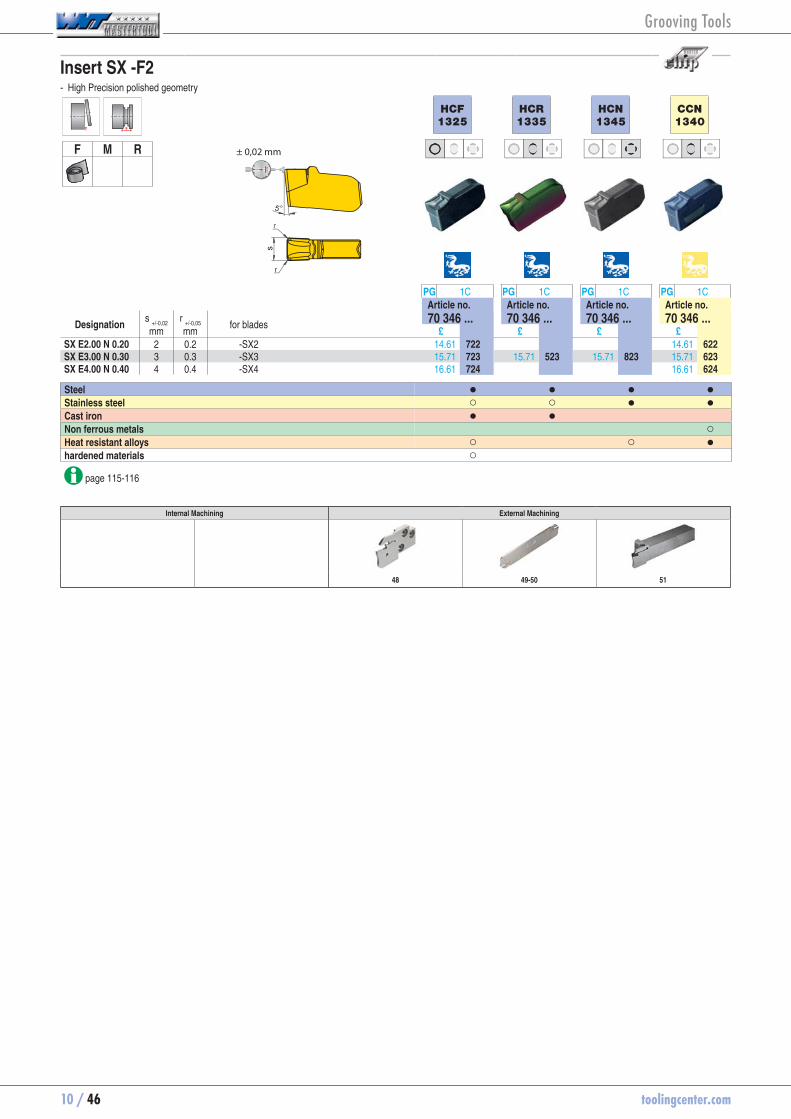
Insert SX -F2 - High Precision polished geometry
F M R ± 0,02 mm
HCF
1325
HCR
1335
HCN
1345
CCN
1340
PG 1C PG 1C PG 1C PG 1CArticle no. Article no. Article no. Article no.
Designation s
+/-0,02r
+/-0,05 for blades 70 346 ... 70 346 ... 70 346 ... 70 346 ...mm mm £ £ £ £
SX E2.00 N 0.20 2 0.2 -SX2 14.61 70346722 14.61 70346622SX E3.00 N 0.30 3 0.3 -SX3 15.71 70346723 15.71 70346523 15.71 70346823 15.71 70346623SX E4.00 N 0.40 4 0.4 -SX4 16.61 70346724 16.61 70346624
Steel ● ● ● ●Stainless steel ○ ○ ● ●Cast iron ● ● Non ferrous metals ○Heat resistant alloys ○ ○ ●hardened materials ○
page 115-116
Internal Machining External Machining
48 49-50 51
Grooving Tools
toolingcenter.com 10 / 47
10
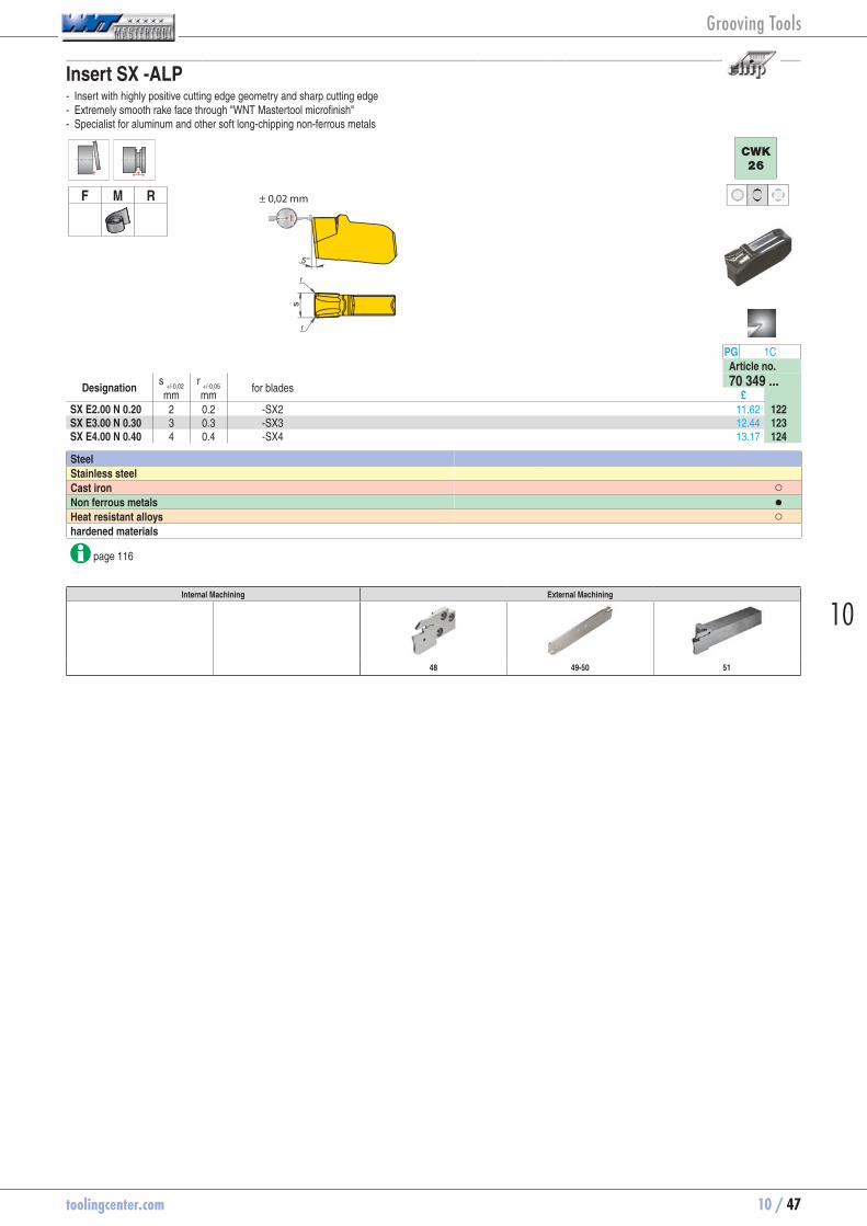
Insert SX -ALP - Insert with highly positive cutting edge geometry and sharp cutting edge - Extremely smooth rake face through "WNT Mastertool microfinish" - Specialist for aluminum and other soft long-chipping non-ferrous metals
F M R ± 0,02 mm
CWK
26
PG 1CArticle no.
Designation s
+/-0,02r
+/-0,05 for blades 70 349 ...mm mm £
SX E2.00 N 0.20 2 0.2 -SX2 11.62 70349122SX E3.00 N 0.30 3 0.3 -SX3 12.44 70349123SX E4.00 N 0.40 4 0.4 -SX4 13.17 70349124
Steel Stainless steel Cast iron ○Non ferrous metals ●Heat resistant alloys ○hardened materials
page 116
Internal Machining External Machining
48 49-50 51
Grooving Tools

10 / 48 toolingcenter.com
Radial grooving module SX - for parting, grooving and finish turning
l3
sf
h 3Tmax
h 2 h 1Dmax
Illustrations show right-hand versions
Right-hand Left-hand
PG 2C PG 2CArticle no. Article no.
Designation h
1 s f l
3 h
2 h
3 D
max T
max. for grooving inserts 70 896 ... 70 897 ...
mm mm mm mm mm mm mm mm £ £E20 R/L 20-SX2 20 2 4.82 22 24 27 60 20.0 SX .2.. 71.84 70896020 71.84 70897020E20 R/L 20-SX3 20 3 4.45 22 24 27 60 20.0 SX .3.. 71.84 70896120 71.84 70897120 E25 R/L 20-SX2 25 2 6.32 22 30 75 20.0 SX .2.. 72.37 70896025 72.37 70897025E25 R/L 25-SX3 25 3 5.95 27 30 75 25.0 SX .3.. 72.37 70896125 72.37 70897125E25 R/L 35-SX3 25 3 5.95 37 30 75 35.0 SX .3.. 73.07 70896225 73.07 70897225E25 R/L 25-SX4 25 4 6.45 27 30 75 25.0 SX .4.. 72.37 70896325 72.37 70897325E25 R/L 35-SX4 25 4 6.45 37 30 75 35.0 SX .4.. 73.07 70896425 73.07 70897425 E32 R/L 35-SX3 32 3 5.95 37 38 96 35.0 SX .3.. 74.39 70896032 74.39 70897032E32 R/L 35-SX4 32 4 6.45 37 38 96 35.0 SX .4.. 74.39 70896132 74.39 70897132
PG 2A
Ejector SX
Article no.Spare parts 70 950 ...for grooving inserts £SX .2.. SX 2-3 22.25 70950836SX .3.. SX 2-3 22.25 70950836SX .4.. SX 4-6 22.70 70950837
43-47 89-91 93
Grooving Tools

toolingcenter.com 10 / 49
10
Blade SX Standard
l1
h 2
bb 1b
N
R/Ls
150°
T max
Illustrations show right-hand versions
PG 2AArticle no.
Designation s h
2 b l
1 b
1 T
max. for grooving
inserts R/L/N 70 884 ...
mm mm mm mm mm £XLCF L 2602-SX2 2 26 2.4 110 1.5 25.0 SX .2.. L 74.04 70884212XLCF L 3202-SX2 2 32 2.4 150 1.5 25.0 SX .2.. L 77.46 70884202 XLCF R 2602-SX2 2 26 2.4 110 1.5 25.0 SX .2.. R 74.04 70884012XLCF R 3202-SX2 2 32 2.4 150 1.5 25.0 SX .2.. R 77.46 70884002 XLCF N 2603-SX3 3 26 2.4 110 35.0 SX .3.. N 74.04 70884113XLCF N 3203-SX3 3 32 2.4 150 50.0 SX .3.. N 77.46 70884103XCLF N 2604-SX4 4 26 3.2 110 40.0 SX .4.. N 74.04 70884114XLCF N 3204-SX4 4 32 3.2 150 50.0 SX .4.. N 77.46 70884104XLCF N 3205-SX5 5 32 4.2 150 55.0 SX .5.. N 77.46 70884105XLCF N 3206-SX6 6 32 5.2 150 60.0 SX .6.. N 77.46 70884106
PG 2A
Ejector SX
Article no.Spare parts 70 950 ...for grooving inserts £SX .2.. SX 2-3 22.25 70950836SX .3.. SX 2-3 22.25 70950836SX .4.. SX 4-6 22.70 70950837SX .5.. SX 4-6 22.70 70950837SX .6.. SX 4-6 22.70 70950837
43-47 95-96 94
Grooving Tools

10 / 50 toolingcenter.com
Blade SX reinforced
l1
h 2
Dmax
s b b 1 T max
Illustrations show left-hand versions
PG 2AArticle no.
Designation s h
2 b l
1 b
1 D
max T
max. for grooving
inserts R/L/N 70 879 ...
mm mm mm mm mm mm £XLCF L 2608-SX2 2 26 1.5 110 8 44 22.0 SX .2.. L 113.33 70879212XLCF L 2608-SX3 3 26 2.5 110 8 44 22.0 SX .3.. L 113.33 70879213XLCF L 3208-SX3 3 32 2.5 110 8 66 33.0 SX .3.. L 106.58 70879203XLCF L 3208-SX4 4 32 3.4 110 8 66 33.0 SX .4.. L 106.58 70879204 XLCF R 2608-SX2 2 26 1.5 110 8 44 22.0 SX .2.. R 113.33 70879012XLCF R 2608-SX3 3 26 2.5 110 8 44 22.0 SX .3.. R 113.33 70879013XLCF R 3208-SX3 3 32 2.5 110 8 66 33.0 SX .3.. R 106.58 70879003XLCF R 3208-SX4 4 32 3.4 110 8 66 33.0 SX .4.. R 106.58 70879004
Page(s) 20 (Chapter 16): VDI-Holder
PG 2A
Ejector SX
Article no.Spare parts 70 950 ...for grooving inserts £SX .2.. SX 2-3 22.25 70950836SX .3.. SX 2-3 22.25 70950836SX .4.. SX 4-6 22.70 70950837
43-47 95-96 94
Grooving Tools
toolingcenter.com 10 / 51
10
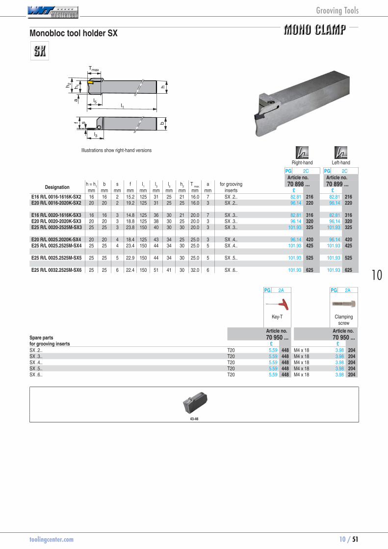
Monobloc tool holder SX
l1
h 2f s
h 1a
h
l5
l3
Tmax
b
Illustrations show right-hand versions
Right-hand Left-hand
PG 2C PG 2CArticle no. Article no.
Designation h = h
1 b s f l
1 l
3 l
5 h
2 T
max. a for grooving
inserts 70 898 ... 70 899 ...
mm mm mm mm mm mm mm mm mm mm £ £E16 R/L 0016-1616K-SX2 16 16 2 15.2 125 31 25 21 16.0 7 SX .2.. 82.81 70898216 82.81 70899216E20 R/L 0016-2020K-SX2 20 20 2 19.2 125 31 25 25 16.0 3 SX .2.. 96.14 70898220 96.14 70899220 E16 R/L 0020-1616K-SX3 16 16 3 14.8 125 36 30 21 20.0 7 SX .3.. 82.81 70898316 82.81 70899316E20 R/L 0020-2020K-SX3 20 20 3 18.8 125 38 30 25 20.0 3 SX .3.. 96.14 70898320 96.14 70899320E25 R/L 0020-2525M-SX3 25 25 3 23.8 150 40 30 30 20.0 3 SX .3.. 101.93 70898325 101.93 70899325 E20 R/L 0025.2020K-SX4 20 20 4 18.4 125 43 34 25 25.0 3 SX .4.. 96.14 70898420 96.14 70899420E25 R/L 0025.2525M-SX4 25 25 4 23.4 150 44 34 30 25.0 5 SX .4.. 101.93 70898425 101.93 70899425 E25 R/L 0025.2525M-SX5 25 25 5 22.9 150 44 34 30 25.0 5 SX .5.. 101.93 70898525 101.93 70899525 E25 R/L 0032.2525M-SX6 25 25 6 22.4 150 51 41 30 32.0 6 SX .6.. 101.93 70898625 101.93 70899625
PG 2A PG 2A
Key-T Clamping screw
Article no. Article no.Spare parts 70 950 ... 70 950 ...for grooving inserts £ £SX .2.. T20 5.59 70950448 M4 x 18 3.98 70950204SX .3.. T20 5.59 70950448 M4 x 18 3.98 70950204SX .4.. T20 5.59 70950448 M4 x 18 3.98 70950204SX .5.. T20 5.59 70950448 M4 x 18 3.98 70950204SX .6.. T20 5.59 70950448 M4 x 18 3.98 70950204
43-46
Grooving Tools

10 / 52 toolingcenter.com
Insert FX -F1 - Excellent cutting geometry with low cutting forces - Very good swarf control also with low feed rates - Reduced built-up edge
F M R
± 0,13 mm
HCF
1325
HCN
1345
CCN
1340
CWX
25
PG 1A PG 1A PG 1A PG 1AArticle no. Article no. Article no. Article no.
Designation R/L/N s
-0,1 K r
+/-0,05 for modules 70 331 ... 70 331 ... 70 331 ... 70 331 ...mm mm £ £ £ £
FX 2.2 L 5-F1 L 2.2 5 0.15 E.. R/L ..-FX 2.2 11.17 70331847 11.17 70331647FX 3.1 L 5-F1 L 3.1 5 0.20 E.. R/L ..-FX 3.1 11.17 70331851 11.17 70331651FX 3.1 L 8-F1 L 3.1 8 0.20 E.. R/L ..-FX 3.1 11.17 70331855 FX 2.2 N 0.15-F1 N 2.2 0 0.15 E.. R/L ..-FX 2.2 11.17 70331748 11.17 70331848 11.17 70331648 11.17 70331198FX 3.1 N 0.20-F1 N 3.1 0 0.20 E.. R/L ..-FX 3.1 11.17 70331752 11.17 70331852 11.17 70331652 11.17 70331202FX 3.1 N 0.40-F1 N 3.1 0 0.40 E.. R/L ..-FX 3.1 11.17 70331756 11.17 70331856 11.17 70331656 11.17 70331206FX 4.1 N 0.20-F1 N 4.1 0 0.20 E.. R/L ..-FX 4.1 11.98 70331760 11.98 70331860 11.98 70331660 11.98 70331210FX 4.1 N 0.50-F1 N 4.1 0 0.50 E.. R/L ..-FX 4.1 11.98 70331864 11.98 70331214 FX 2.2 R 5-F1 R 2.2 5 0.15 E.. R/L ..-FX 2.2 11.17 70331849 11.17 70331649FX 3.1 R 5-F1 R 3.1 5 0.20 E.. R/L ..-FX 3.1 11.17 70331853 11.17 70331653FX 3.1 R 8-F1 R 3.1 8 0.20 E.. R/L ..-FX 3.1 11.17 70331857
Steel ● ● ● ●Stainless steel ○ ● ● ○Cast iron ● ●Non ferrous metals ○ Heat resistant alloys ○ ○ ● ○hardened materials ○ ○
page 115-116
Note: reduce feed rate by 20-50% with R/L version!
Internal Machining External Machining
58 60 59
Grooving Tools

toolingcenter.com 10 / 53
10
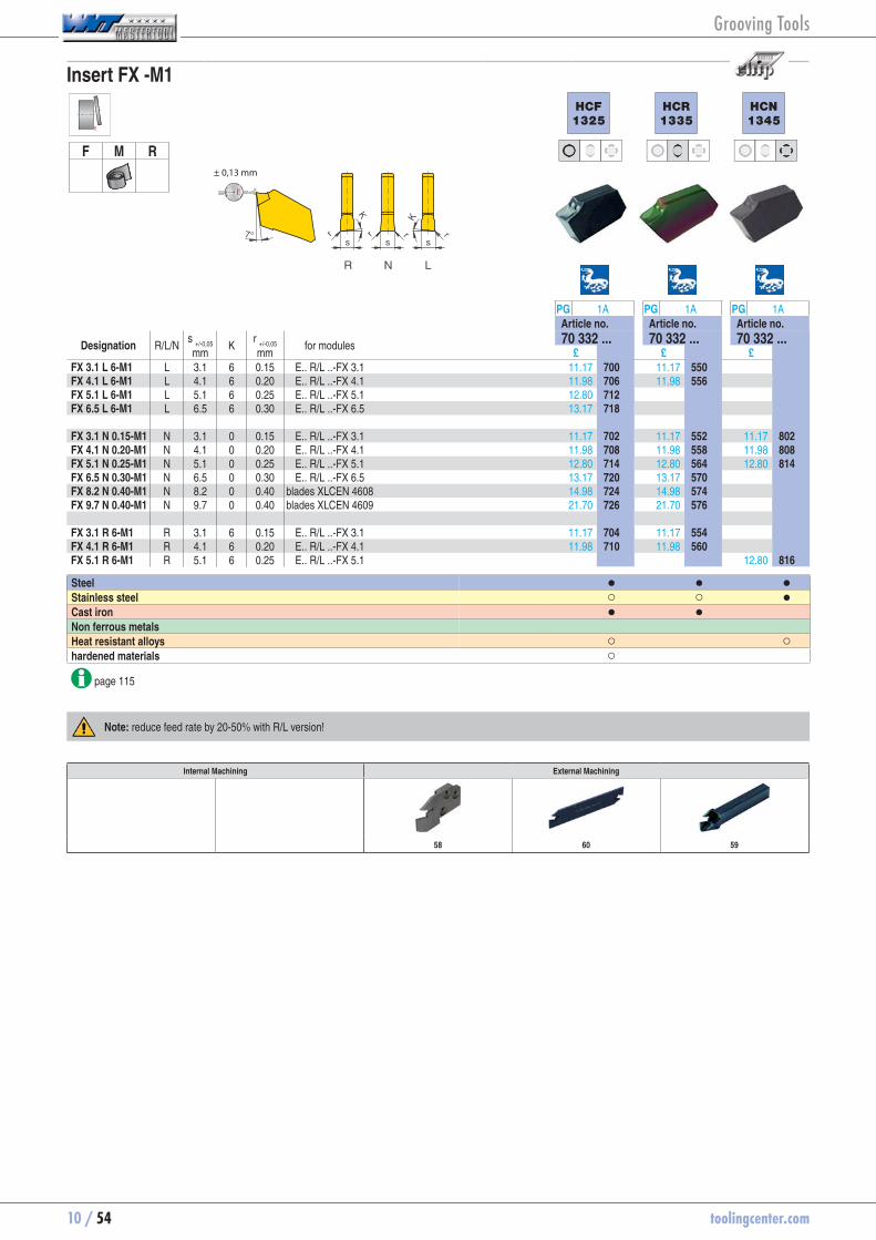
Insert FX -M1
F M R
± 0,13 mm
HCF
1325
HCR
1335
HCN
1345
CCN
1340
CWX
25
PG 1A PG 1A PG 1A PG 1A PG 1AArticle no. Article no. Article no. Article no. Article no.
Designation R/L/N s
-0,1 K r
+/-0,05 for modules 70 330 ... 70 330 ... 70 330 ... 70 330 ... 70 330 ...mm mm £ £ £ £ £
FX 2.2 L 4-M1 L 2.2 4 0.1 E.. R/L ..-FX 2.2 11.17 70330700 11.17 70330550 11.17 70330600 11.17 70330200 FX 2.2 N 0.10-M1 N 2.2 0 0.1 E.. R/L ..-FX 2.2 11.17 70330702 11.17 70330552 11.17 70330802 11.44 70330602 11.17 70330202 FX 2.2 R 4-M1 R 2.2 4 0.1 E.. R/L ..-FX 2.2 11.17 70330704 11.17 70330554 11.17 70330604 11.17 70330204
Steel ● ● ● ● ●Stainless steel ○ ○ ● ● ○Cast iron ● ● ●Non ferrous metals ○ Heat resistant alloys ○ ○ ● ○hardened materials ○ ○
page 115-116
Note: reduce feed rate by 20-50% with R/L version!
Internal Machining External Machining
58 60 59
Grooving Tools
10 / 54 toolingcenter.com
Insert FX -M1
F M R
± 0,13 mm
HCF
1325
HCR
1335
HCN
1345
PG 1A PG 1A PG 1AArticle no. Article no. Article no.
Designation R/L/N s
+/-0,05 K r
+/-0,05 for modules 70 332 ... 70 332 ... 70 332 ...mm mm £ £ £
FX 3.1 L 6-M1 L 3.1 6 0.15 E.. R/L ..-FX 3.1 11.17 70332700 11.17 70332550FX 4.1 L 6-M1 L 4.1 6 0.20 E.. R/L ..-FX 4.1 11.98 70332706 11.98 70332556FX 5.1 L 6-M1 L 5.1 6 0.25 E.. R/L ..-FX 5.1 12.80 70332712FX 6.5 L 6-M1 L 6.5 6 0.30 E.. R/L ..-FX 6.5 13.17 70332718 FX 3.1 N 0.15-M1 N 3.1 0 0.15 E.. R/L ..-FX 3.1 11.17 70332702 11.17 70332552 11.17 70332802FX 4.1 N 0.20-M1 N 4.1 0 0.20 E.. R/L ..-FX 4.1 11.98 70332708 11.98 70332558 11.98 70332808FX 5.1 N 0.25-M1 N 5.1 0 0.25 E.. R/L ..-FX 5.1 12.80 70332714 12.80 70332564 12.80 70332814FX 6.5 N 0.30-M1 N 6.5 0 0.30 E.. R/L ..-FX 6.5 13.17 70332720 13.17 70332570FX 8.2 N 0.40-M1 N 8.2 0 0.40 blades XLCEN 4608 14.98 70332724 14.98 70332574FX 9.7 N 0.40-M1 N 9.7 0 0.40 blades XLCEN 4609 21.70 70332726 21.70 70332576 FX 3.1 R 6-M1 R 3.1 6 0.15 E.. R/L ..-FX 3.1 11.17 70332704 11.17 70332554FX 4.1 R 6-M1 R 4.1 6 0.20 E.. R/L ..-FX 4.1 11.98 70332710 11.98 70332560FX 5.1 R 6-M1 R 5.1 6 0.25 E.. R/L ..-FX 5.1 12.80 70332816
Steel ● ● ●Stainless steel ○ ○ ●Cast iron ● ● Non ferrous metals Heat resistant alloys ○ ○hardened materials ○
page 115
Note: reduce feed rate by 20-50% with R/L version!
Internal Machining External Machining
58 60 59
Grooving Tools

toolingcenter.com 10 / 55
10
Insert FX -M1
F M R
± 0,13 mm
CWP
40
CCN
1340
CWX
25
PG 1A PG 1A PG 1AArticle no. Article no. Article no.
Designation R/L/N s
+/-0,05 K r
+/-0,05 for modules 70 332 ... 70 332 ... 70 332 ...mm mm £ £ £
FX 3.1 L 6-M1 L 3.1 6 0.15 E.. R/L ..-FX 3.1 7.67 70332500 11.17 70332600 11.17 70332200FX 4.1 L 6-M1 L 4.1 6 0.20 E.. R/L ..-FX 4.1 11.98 70332606 11.98 70332206FX 5.1 L 6-M1 L 5.1 6 0.25 E.. R/L ..-FX 5.1 12.80 70332212FX 6.5 L 6-M1 L 6.5 6 0.30 E.. R/L ..-FX 6.5 13.17 70332218 FX 3.1 N 0.15-M1 N 3.1 0 0.15 E.. R/L ..-FX 3.1 7.67 70332502 11.17 70332602 11.17 70332202FX 4.1 N 0.20-M1 N 4.1 0 0.20 E.. R/L ..-FX 4.1 11.98 70332608 11.98 70332208FX 5.1 N 0.25-M1 N 5.1 0 0.25 E.. R/L ..-FX 5.1 12.80 70332614 12.80 70332214FX 6.5 N 0.30-M1 N 6.5 0 0.30 E.. R/L ..-FX 6.5 13.17 70332220FX 8.2 N 0.40-M1 N 8.2 0 0.40 blades XLCEN 4608 14.98 70332624 14.98 70332224FX 9.7 N 0.40-M1 N 9.7 0 0.40 blades XLCEN 4609 21.70 70332626 21.70 70332226 FX 3.1 R 6-M1 R 3.1 6 0.15 E.. R/L ..-FX 3.1 7.67 70332504 11.17 70332604 11.17 70332204FX 4.1 R 6-M1 R 4.1 6 0.20 E.. R/L ..-FX 4.1 11.98 70332610 11.98 70332210
Steel ● ● ●Stainless steel ● ○Cast iron ●Non ferrous metals ○ Heat resistant alloys ● ○hardened materials ○
page 115-116
Note: reduce feed rate by 20-50% with R/L version!
Internal Machining External Machining
58 60 59
Grooving Tools
10 / 56 toolingcenter.com
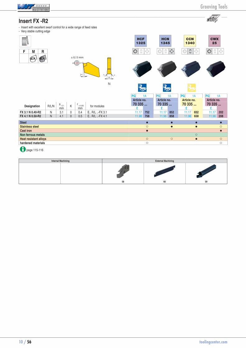
Insert FX -R2 - Insert with excellent swarf control for a wide range of feed rates - Very stable cutting edge
F M R± 0,13 mm
HCF
1325
HCN
1345
CCN
1340
CWX
25
PG 1A PG 1A PG 1A PG 1AArticle no. Article no. Article no. Article no.
Designation R/L/N s
-0,1 K r
+/-0,05 for modules 70 335 ... 70 335 ... 70 335 ... 70 335 ...mm mm £ £ £ £
FX 3.1 N 0.40-R2 N 3.1 0 0.4 E.. R/L ..-FX 3.1 11.17 70335752 11.17 70335852 11.17 70335652 11.17 70335202FX 4.1 N 0.50-R2 N 4.1 0 0.5 E.. R/L ..-FX 4.1 11.98 70335758 11.98 70335858 11.98 70335658 11.98 70335208
Steel ● ● ● ●Stainless steel ○ ● ● ○Cast iron ● ●Non ferrous metals ○ Heat resistant alloys ○ ○ ● ○hardened materials ○ ○
page 115-116
Internal Machining External Machining
58 60 59
Grooving Tools

toolingcenter.com 10 / 57
10
Insert FX -ALP - Insert with highly positive cutting edge geometry and sharp cutting edge - Extremely smooth rake face through "WNT Mastertool microfinish" - Reduced built-up edge
F M R± 0,13 mm
CWK
26
PG 1AArticle no.
Designation R/L/N s
-0,1 K r
+/-0,05 for modules 70 334 ...mm mm £
FX 3.1 N 0.15 N 3.1 0 0.15 E.. R/L ..-FX 3.1 10.44 70334652FX 4.1 N 0.15 N 4.1 0 0.15 E.. R/L ..-FX 4.1 11.17 70334654FX 2.2 N 0.10 N 2.2 0 0.10 E.. R/L ..-FX 2.2 10.44 70334650
Steel Stainless steel Cast iron ○Non ferrous metals ●Heat resistant alloys ○hardened materials
page 116
Internal Machining External Machining
58 60 59
Grooving Tools

10 / 58 toolingcenter.com
Radial grooving module FX short/long - For parting and grooving
Dmax
h 3
l3
Illustrations show right-hand versionsRight-hand Left-hand
PG 2C PG 2CArticle no. Article no.
Designation h
1 s f l
3 h
2 h
3 D
max T
max. for grooving inserts 70 875 ... 70 876 ...
mm mm mm mm mm mm mm mm £ £E20 R/L 20-FX 2.2 20 2.2 4.67 22 24 27 60 20.0 FX 2.2 .. 71.84 70875020 71.84 70876020E20 R/L 20-FX 3.1 20 3.1 4.75 22 24 27 60 20.0 FX 3.1 .. 71.84 70875120 71.84 70876120E20 R/L 20-FX 4.1 20 4.1 4.85 22 24 27 60 20.0 FX 4.1 .. 71.84 70875220 71.84 70876220 E25 R/L 20-FX 2.2 25 2.2 6.17 22 30 75 20.0 FX 2.2 .. 72.37 70875025 72.37 70876025E25 R/L 25-FX 3.1 25 3.1 6.25 27 30 75 25.0 FX 3.1 .. 72.37 70875125 72.37 70876125E25 R/L 25-FX 4.1 25 4.1 6.35 27 30 75 25.0 FX 4.1 .. 72.37 70875225 72.37 70876225E25 R/L 25-FX 5.1 25 5.1 6.45 27 30 75 25.0 FX 5.1 .. 72.37 70875325 72.37 70876325E25 R/L 25-FX 6.5 25 6.5 6.55 27 30 75 25.0 FX 6.5 .. 72.37 70875425 72.37 70876425E25 R/L 35-FX 3.1 25 3.1 2.40 37 30 75 35.0 FX 3.1 .. 73.07 70875525 73.07 70876525E25 R/L 35-FX 4.1 25 4.1 3.20 37 30 75 35.0 FX 4.1 .. 73.07 70875625 73.07 70876625E25 R/L 35-FX 5.1 25 5.1 4.00 37 30 75 35.0 FX 5.1 .. 73.07 70875725 73.07 70876725E25 R/L 35-FX 6.5 25 6.5 5.20 37 30 75 35.0 FX 6.5 .. 73.07 70875825 73.07 70876825 E32 R/L 32-FX 3.1 32 3.1 6.25 34 38 96 32.0 FX 3.1 .. 74.39 70875032 74.39 70876032E32 R/L 32-FX 4.1 32 4.1 6.35 34 38 96 32.0 FX 4.1 .. 74.39 70875132 74.39 70876132E32 R/L 32-FX 5.1 32 5.1 6.45 34 38 96 32.0 FX 5.1 .. 74.39 70875232 74.39 70876232E32 R/L 32-FX 6.5 32 6.5 6.55 34 38 96 32.0 FX 6.5 .. 74.39 70875332 74.39 70876332E32 R/L 45-FX 3.1 32 3.1 2.40 47 38 96 45.0 FX 3.1 .. 75.61 70875432 75.61 70876432E32 R/L 45-FX 4.1 32 4.1 3.20 47 38 96 45.0 FX 4.1 .. 75.61 70875532 75.61 70876532E32 R/L 45-FX 5.1 32 5.1 4.00 47 38 96 45.0 FX 5.1 .. 75.61 70875632 75.61 70876632E32 R/L 45-FX 6.5 32 6.5 5.20 47 38 96 45.0 FX 6.5 .. 75.61 70875732 75.61 70876732
PG 2A
Ejector
Article no.Spare parts 70 950 ...for grooving inserts £FX 2.2 .. 3.64 70950375FX 3.1 .. 3.64 70950376FX 4.1 .. 3.64 70950376FX 5.1 .. 3.64 70950376FX 6.5 .. 3.64 70950376
52-57 89-91 93
Grooving Tools

toolingcenter.com 10 / 59
10
Monobloc tool FX - Scope of supply: Toolholder incl. ejector
h 2
b
sf
h 1
l1l3
h
Dmax
Illustrations show right-hand versionsRight-hand Left-hand
PG 2A PG 2AArticle no. Article no.
Designation h = h
1 b l
1 l
3 h
2 s f D
max for grooving
inserts 70 836 ... 70 837 ...
mm mm mm mm mm mm mm mm £ £XLCE R/L 1010 M-FX2.2 10 10 150 19.4 21 2.2 10.25 30 FX 2.2 .. 83.07 70836101 83.07 70837101XLCE R/L 1212 F-FX2.2 12 12 80 21.0 21 2.2 12.25 30 FX 2.2 .. 78.95 70836102 83.07 70837102XLCE R/L 1212 M-FX2.2 12 12 150 19.4 21 2.2 12.25 30 FX 2.2 .. 83.07 70836103 83.07 70837103XLCE R/L 1414 M-FX2.2 14 14 150 19.4 21 2.2 14.25 30 FX 2.2 .. 85.61 70836104 85.61 70837104XLCE R/L 1612 H-FX2.2 16 12 100 21.0 21 2.2 12.25 30 FX 2.2 .. 78.95 70836105 78.95 70837105 XLCF R/L 1612 H-FX3.1 16 12 100 21.4 25 3.1 12.35 35 FX 3.1 .. 78.95 70836106 78.95 70837106XLCF R/L 2016 K-FX3.1 20 16 125 26.4 26 3.1 16.35 40 FX 3.1 .. 88.07 70836107 88.07 70837107XLCF R/L 2520 M-FX3.1 25 20 150 35.2 34 3.1 20.35 50 FX 3.1 .. 90.44 70836108 90.44 70837108 XLCF R/L 2016 K-FX4.1 20 16 125 26.4 26 4.1 16.45 40 FX 4.1 .. 88.07 70836109 88.07 70837109XLCF R/L 2520 M-FX4.1 25 20 150 35.2 34 4.1 20.45 50 FX 4.1 .. 90.44 70836110 90.44 70837110
PG 2A
Ejector
Article no.Spare parts 70 950 ...for grooving inserts £FX 2.2 .. 3.64 70950375FX 3.1 .. 3.64 70950376FX 4.1 .. 3.64 70950376
52-57
Grooving Tools

10 / 60 toolingcenter.com
Blade FX - Supply details: blade and ejector
h 2
l1T m
axb
150°
PG 2AArticle no.
Designation h
2 b l
1
s T
max. for grooving
inserts 70 832 ...
mm mm mm mm £XLCEN 2602 J 22 26 1.65 110 2,2 25.0 FX 2.2 .. 67.72 70832101XLCFN 2603 J 31 26 2.40 110 3,1 35.0 FX 3.1 .. 66.32 70832102XLCFN 2604 J 41 26 3.20 110 4,1 40.0 FX 4.1 .. 66.32 70832103 XLCEN 3202 M 22 32 1.65 150 2,2 30.0 FX 2.2 .. 67.72 70832004XLCFN 3203 M 31 32 2.40 150 3,1 50.0 FX 3.1 .. 68.77 70832104XLCFN 3204 M 41 32 3.20 150 4,1 50.0 FX 4.1 .. 74.21 70832105XLCFN 3205 M 51 32 4.00 150 5,1 55.0 FX 5.1 .. 81.40 70832106XLCFN 3206 M 65 32 5.20 150 6,5 55.0 FX 6.5 .. 88.07 70832107 XLCEN 4608 S 82 46 6.80 250 8,2 80.0 FX 8.2 .. 210.18 70832108XLCEN 4609 S 97 46 8.00 250 9,7 80.0 FX 9.7 .. 210.18 70832109
PG 2A
Ejector
Article no.Spare parts 70 950 ...for grooving inserts £FX 2.2 .. 3.64 70950375FX 3.1 .. 3.64 70950376FX 4.1 .. 3.64 70950376FX 5.1 .. 3.64 70950376FX 6.5 .. 3.64 70950376FX 8.2 .. 4.55 70950377FX 9.7 .. 4.55 70950377
52-57 95-96 94
Grooving Tools

toolingcenter.com 10 / 61
10
Grooving insert AX -F50 - very good chip control - D
min minimum groove diameter refers to the outside diameter
F M R
110
00
r
r2,5°
2,5°
s
7°
l
l2 N
CCN
1340
PG 1CArticle no.
Designation R/L/N l s
+/-0,02r
+/-0,05l2
for modules D
min 70 327 ...
mm mm mm mm mm £AX 05 E3.00 N 0.30 N 24 3 0.3 5 E.. R/L.. -AX 05 10 21.97 70327005AX 10 E3.00 N 0.30 N 34 3 0.3 10 E.. R/L.. -AX 10 20 22.79 70327010AX 15 E3.00 N 0.30 N 44 3 0.3 15 E.. R/L.. -AX 15 30 23.96 70327015
Steel ●Stainless steel ●Cast iron Non ferrous metals ○Heat resistant alloys ●hardened materials
page 116
Internal Machining External Machining
62
Grooving Tools
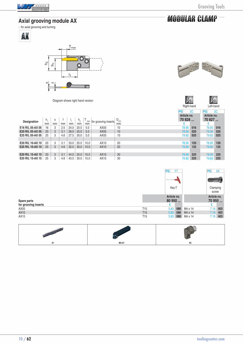
10 / 62 toolingcenter.com
Axial grooving module AX - for axial grooving and turning
s fh 1h 2
Tmax
l1
Diagram shows right hand version
Right-hand Left-hand
PG 2C PG 2CArticle no. Article no.
Designation h
1 s f l
1 h
2 T
max. for grooving inserts
Dmin
70 828 ... 70 827 ...mm mm mm mm mm mm mm £ £
E16 R/L 05-AX 05 16 3 2.5 24.0 20.5 5.0 AX05 10 78.95 70828016 78.95 70827016E20 R/L 05-AX 05 20 3 3.1 28.0 25.0 5.0 AX05 10 78.95 70828020 78.95 70827020E25 R/L 05-AX 05 25 3 4.6 27.5 30.0 5.0 AX05 10 79.82 70828025 79.82 70827025 E20 R/L 10-AX 10 20 3 3.1 33.0 25.0 10.0 AX10 20 78.95 70828120 78.95 70827120E25 R/L 10-AX 10 25 3 4.6 32.5 30.0 10.0 AX10 20 79.82 70828125 79.82 70827125 E20 R/L 15-AX 15 20 3 3.1 44.0 25.0 15.0 AX15 30 78.95 70828220 78.95 70827220E25 R/L 15-AX 15 25 3 4.6 43.5 30.0 15.0 AX15 30 79.82 70828225 79.82 70827225
PG Y7 PG 2A
Key-T Clamping screw
Article no. Article no.Spare parts 80 950 ... 70 950 ...for grooving inserts £ £AX05 T15 5.83 80950088 M4 x 14 7.18 70950403AX10 T15 5.83 80950088 M4 x 14 7.18 70950403AX15 T15 5.83 80950088 M4 x 14 7.18 70950403
61 89+91 93
Grooving Tools

toolingcenter.com 10 / 63
10
Insert LX -M2 - Grooving width 8 and 10 mm - Axial grooving from Ø 500 mm onwards - Internal grooving and turning, from Ø 200 mm onwards
F M R
l2
HCR
1335
CWX
25
PG 1A PG 1AArticle no. Article no.
Designation l s
-/+0,08r
+/-0,1l2
for modules 70 337 ... 70 337 ...mm mm mm mm £ £
LXE 8.00N0.80-M2 19 8 0.8 5 E32 N ..-LX 15.25 70337578 15.25 70337228LXE 10.00N0.80-M2 19 10 0.8 5 E32 N ..-LX 20.33 70337582 20.33 70337232
Steel ● ●Stainless steel ○ ○Cast iron ● ●Non ferrous metals Heat resistant alloys ○hardened materials ○
page 115
Insert LX -M3 - Grooving width 8 and 10 mm - Axial grooving from Ø 500 mm onwards - Internal grooving and turning, from Ø 200 mm onwards
F M R
l2
HCR
1335
CWX
25
PG 1A PG 1AArticle no. Article no.
Designation l s
-/+0,08r
+/-0,1l2
for modules 70 337 ... 70 337 ...mm mm mm mm £ £
LXR 4.00N-M3 19 8 4 5 E32 N ..-LX 16.25 70337518 16.25 70337208
Steel ● ●Stainless steel ○ ○Cast iron ● ●Non ferrous metals Heat resistant alloys ○hardened materials ○
page 115
Internal Machining External Machining
64 91 64 65 89-94
Grooving Tools

10 / 64 toolingcenter.com
Axial and radial grooving module LX - Grooving width 8 and 10 mm - Axial grooving from Ø 500 mm onwards - Internal grooving and turning, from Ø 200 mm onwards
l1
h 1h 2Tmax
sf
f
Neutral
PG 2CArticle no.
Designation s f l
1 h
1 h
2 T
max. 1 T
max. 2 T
max. 3 for grooving
inserts 70 835 ...
mm mm mm mm mm mm mm mm £E32 N 25-LX 8 / 10 3.4 27 32 44 25.0 19 14 LX .. 80.18 70835032E32 N 32-LX 8 / 10 3.4 37 32 44 32.0 26 21 LX .. 80.18 70835132E32 N 45-LX 8 / 10 3.4 47 32 44 45.0 39 34 LX .. 80.18 70835232
Radial grooving Axial grooving Dmin > 500 mm Internal grooving Dmin > 200 mm
Tm
ax1
Tmax
2
Tm
ax3
PG 2A PG 2A
Key-T Clamping screw
Article no. Article no.Spare parts 70 950 ... 70 950 ...for grooving inserts £ £LX .. T20 5.59 70950448 M4 x 18 3.98 70950204
63 89-91 93
Grooving Tools
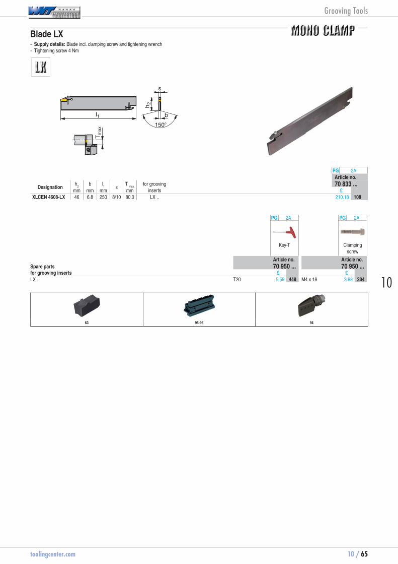
toolingcenter.com 10 / 65
10
Blade LX - Supply details: Blade incl. clamping screw and tightening wrench - Tightening screw 4 Nm
l1
h 2
T max
b
150°
s
PG 2AArticle no.
Designation h
2 b l
1
s T
max. for grooving
inserts 70 833 ...
mm mm mm mm £XLCEN 4608-LX 46 6.8 250 8/10 80.0 LX .. 210.18 70833108
PG 2A PG 2A
Key-T Clamping screw
Article no. Article no.Spare parts 70 950 ... 70 950 ...for grooving inserts £ £LX .. T20 5.59 70950448 M4 x 18 3.98 70950204
63 95-96 94
Grooving Tools
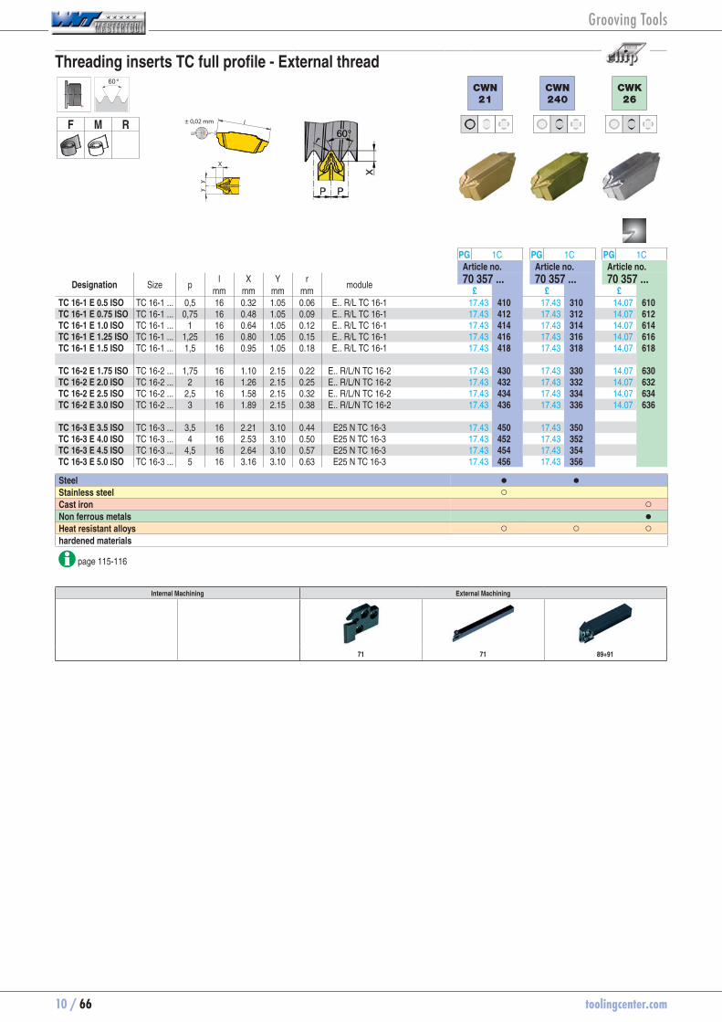
10 / 66 toolingcenter.com
Threading inserts TC full profile - External thread60°
F M R ± 0,02 mm
X
CWN
21
CWN
240
CWK
26
PG 1C PG 1C PG 1CArticle no. Article no. Article no.
Designation Size p l X Y r
module 70 357 ... 70 357 ... 70 357 ...mm mm mm mm £ £ £
TC 16-1 E 0.5 ISO TC 16-1 ... 0,5 16 0.32 1.05 0.06 E.. R/L TC 16-1 17.43 70357410 17.43 70357310 14.07 70357610TC 16-1 E 0.75 ISO TC 16-1 ... 0,75 16 0.48 1.05 0.09 E.. R/L TC 16-1 17.43 70357412 17.43 70357312 14.07 70357612TC 16-1 E 1.0 ISO TC 16-1 ... 1 16 0.64 1.05 0.12 E.. R/L TC 16-1 17.43 70357414 17.43 70357314 14.07 70357614TC 16-1 E 1.25 ISO TC 16-1 ... 1,25 16 0.80 1.05 0.15 E.. R/L TC 16-1 17.43 70357416 17.43 70357316 14.07 70357616TC 16-1 E 1.5 ISO TC 16-1 ... 1,5 16 0.95 1.05 0.18 E.. R/L TC 16-1 17.43 70357418 17.43 70357318 14.07 70357618 TC 16-2 E 1.75 ISO TC 16-2 ... 1,75 16 1.10 2.15 0.22 E.. R/L/N TC 16-2 17.43 70357430 17.43 70357330 14.07 70357630TC 16-2 E 2.0 ISO TC 16-2 ... 2 16 1.26 2.15 0.25 E.. R/L/N TC 16-2 17.43 70357432 17.43 70357332 14.07 70357632TC 16-2 E 2.5 ISO TC 16-2 ... 2,5 16 1.58 2.15 0.32 E.. R/L/N TC 16-2 17.43 70357434 17.43 70357334 14.07 70357634TC 16-2 E 3.0 ISO TC 16-2 ... 3 16 1.89 2.15 0.38 E.. R/L/N TC 16-2 17.43 70357436 17.43 70357336 14.07 70357636 TC 16-3 E 3.5 ISO TC 16-3 ... 3,5 16 2.21 3.10 0.44 E25 N TC 16-3 17.43 70357450 17.43 70357350TC 16-3 E 4.0 ISO TC 16-3 ... 4 16 2.53 3.10 0.50 E25 N TC 16-3 17.43 70357452 17.43 70357352TC 16-3 E 4.5 ISO TC 16-3 ... 4,5 16 2.64 3.10 0.57 E25 N TC 16-3 17.43 70357454 17.43 70357354TC 16-3 E 5.0 ISO TC 16-3 ... 5 16 3.16 3.10 0.63 E25 N TC 16-3 17.43 70357456 17.43 70357356
Steel ● ● Stainless steel ○ Cast iron ○Non ferrous metals ●Heat resistant alloys ○ ○ ○hardened materials
page 115-116
Internal Machining External Machining
71 71 89+91
Grooving Tools
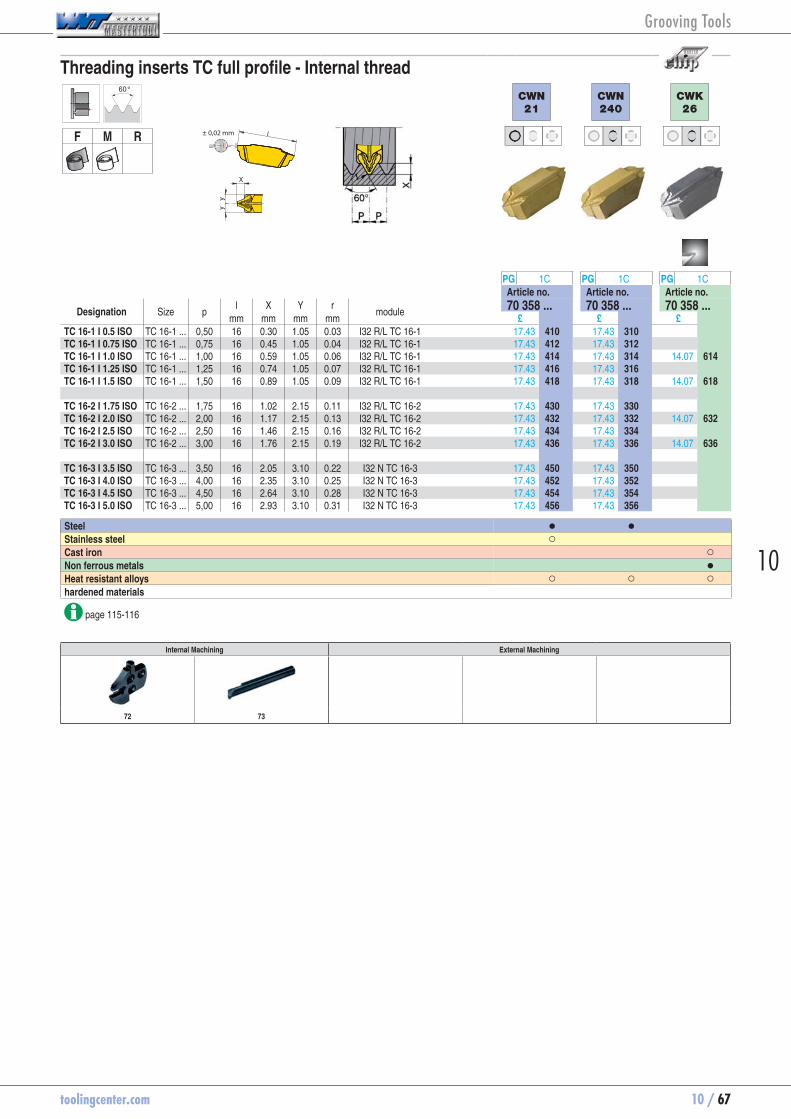
toolingcenter.com 10 / 67
10
Threading inserts TC full profile - Internal thread60°
F M R ± 0,02 mm
X
CWN
21
CWN
240
CWK
26
PG 1C PG 1C PG 1CArticle no. Article no. Article no.
Designation Size p l X Y r
module 70 358 ... 70 358 ... 70 358 ...mm mm mm mm £ £ £
TC 16-1 I 0.5 ISO TC 16-1 ... 0,50 16 0.30 1.05 0.03 I32 R/L TC 16-1 17.43 70358410 17.43 70358310TC 16-1 I 0.75 ISO TC 16-1 ... 0,75 16 0.45 1.05 0.04 I32 R/L TC 16-1 17.43 70358412 17.43 70358312TC 16-1 I 1.0 ISO TC 16-1 ... 1,00 16 0.59 1.05 0.06 I32 R/L TC 16-1 17.43 70358414 17.43 70358314 14.07 70358614TC 16-1 I 1.25 ISO TC 16-1 ... 1,25 16 0.74 1.05 0.07 I32 R/L TC 16-1 17.43 70358416 17.43 70358316TC 16-1 I 1.5 ISO TC 16-1 ... 1,50 16 0.89 1.05 0.09 I32 R/L TC 16-1 17.43 70358418 17.43 70358318 14.07 70358618 TC 16-2 I 1.75 ISO TC 16-2 ... 1,75 16 1.02 2.15 0.11 I32 R/L TC 16-2 17.43 70358430 17.43 70358330TC 16-2 I 2.0 ISO TC 16-2 ... 2,00 16 1.17 2.15 0.13 I32 R/L TC 16-2 17.43 70358432 17.43 70358332 14.07 70358632TC 16-2 I 2.5 ISO TC 16-2 ... 2,50 16 1.46 2.15 0.16 I32 R/L TC 16-2 17.43 70358434 17.43 70358334TC 16-2 I 3.0 ISO TC 16-2 ... 3,00 16 1.76 2.15 0.19 I32 R/L TC 16-2 17.43 70358436 17.43 70358336 14.07 70358636 TC 16-3 I 3.5 ISO TC 16-3 ... 3,50 16 2.05 3.10 0.22 I32 N TC 16-3 17.43 70358450 17.43 70358350TC 16-3 I 4.0 ISO TC 16-3 ... 4,00 16 2.35 3.10 0.25 I32 N TC 16-3 17.43 70358452 17.43 70358352TC 16-3 I 4.5 ISO TC 16-3 ... 4,50 16 2.64 3.10 0.28 I32 N TC 16-3 17.43 70358454 17.43 70358354TC 16-3 I 5.0 ISO TC 16-3 ... 5,00 16 2.93 3.10 0.31 I32 N TC 16-3 17.43 70358456 17.43 70358356
Steel ● ● Stainless steel ○ Cast iron ○Non ferrous metals ●Heat resistant alloys ○ ○ ○hardened materials
page 115-116
Internal Machining External Machining
72 73
Grooving Tools
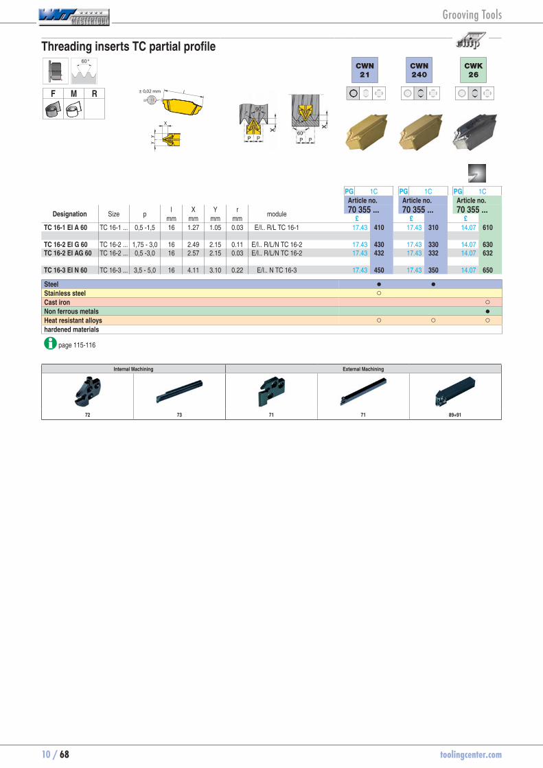
10 / 68 toolingcenter.com
Threading inserts TC partial profile60°
F M R ± 0,02 mm
X
CWN
21
CWN
240
CWK
26
PG 1C PG 1C PG 1CArticle no. Article no. Article no.
Designation Size p l X Y r
module 70 355 ... 70 355 ... 70 355 ...mm mm mm mm £ £ £
TC 16-1 EI A 60 TC 16-1 ... 0,5 -1,5 16 1.27 1.05 0.03 E/I.. R/L TC 16-1 17.43 70355410 17.43 70355310 14.07 70355610 TC 16-2 EI G 60 TC 16-2 ... 1,75 - 3,0 16 2.49 2.15 0.11 E/I.. R/L/N TC 16-2 17.43 70355430 17.43 70355330 14.07 70355630TC 16-2 EI AG 60 TC 16-2 ... 0,5 -3,0 16 2.57 2.15 0.03 E/I.. R/L/N TC 16-2 17.43 70355432 17.43 70355332 14.07 70355632 TC 16-3 EI N 60 TC 16-3 ... 3,5 - 5,0 16 4.11 3.10 0.22 E/I.. N TC 16-3 17.43 70355450 17.43 70355350 14.07 70355650
Steel ● ● Stainless steel ○ Cast iron ○Non ferrous metals ●Heat resistant alloys ○ ○ ○hardened materials
page 115-116
Internal Machining External Machining
72 73 71 71 89+91
Grooving Tools

toolingcenter.com 10 / 69
10
Threading inserts TC full profile55°
F M R ± 0,02 mm
X
CWN
21
CWN
240
CWK
26
PG 1C PG 1C PG 1CArticle no. Article no. Article no.
Designation Size 1/" l X Y r
module 70 359 ... 70 359 ... 70 359 ...mm mm mm mm £ £ £
TC 16-1 EI 28 W TC 16-1 ... 28 16 0.60 1.05 0.12 E/I.. R/L TC 16-1 17.43 70359410 17.43 70359310TC 16-1 EI 26 W TC 16-1 ... 26 16 0.65 1.05 0.13 E/I.. R/L TC 16-1 17.43 70359412 17.43 70359312TC 16-1 EI 24 W TC 16-1 ... 24 16 0.70 1.05 0.14 E/I.. R/L TC 16-1 17.43 70359414 17.43 70359314TC 16-1 EI 20 W TC 16-1 ... 20 16 0.84 1.05 0.17 E/I.. R/L TC 16-1 17.43 70359416 17.43 70359316TC 16-1 EI 19 W TC 16-1 ... 19 16 0.88 1.05 0.17 E/I.. R/L TC 16-1 17.43 70359418 17.43 70359318 14.07 70359618TC 16-1 EI 18 W TC 16-1 ... 18 16 0.93 1.05 0.18 E/I.. R/L TC 16-1 17.43 70359420 17.43 70359320TC 16-1 EI 16 W TC 16-1 ... 16 16 1.05 1.05 0.21 E/I.. R/L TC 16-1 17.43 70359422 17.43 70359322 TC 16-2 EI 14 W TC 16-2 ... 14 16 1.20 2.15 0.23 E/I.. R/L/N TC 16-2 17.43 70359430 17.43 70359330 14.07 70359630TC 16-2 EI 12 W TC 16-2 ... 12 16 1.40 2.15 0.27 E/I.. R/L/N TC 16-2 17.43 70359432 17.43 70359332TC 16-2 EI 11 W TC 16-2 ... 11 16 1.53 2.15 0.30 E/I.. R/L/N TC 16-2 17.43 70359434 17.43 70359334 14.07 70359634TC 16-2 EI 10 W TC 16-2 ... 10 16 1.68 2.15 0.33 E/I.. R/L/N TC 16-2 17.43 70359436 17.43 70359336TC 16-2 EI 9 W TC 16-2 ... 9 16 1.87 2.15 0.36 E/I.. R/L/N TC 16-2 17.43 70359438TC 16-2 EI 8 W TC 16-2 ... 8 16 2.11 2.15 0.41 E/I.. R/L/N TC 16-2 17.43 70359440 TC 16-3 EI 7 W TC 16-3 ... 7 16 2.41 3.10 0.46 E/I.. N TC 16-3 17.43 70359450 17.43 70359350TC 16-3 EI 6 W TC 16-3 ... 6 16 2.81 3.10 0.54 E/I.. N TC 16-3 17.43 70359452TC 16-3 EI 5 W TC 16-3 ... 5 16 3.37 3.10 0.65 E/I.. N TC 16-3 17.43 70359454 17.43 70359354
Steel ● ● Stainless steel ○ Cast iron ○Non ferrous metals ●Heat resistant alloys ○ ○ ○hardened materials
page 115-116
Internal Machining External Machining
72 73 71 71 89+91
Grooving Tools

10 / 70 toolingcenter.com
Threading inserts TC partial profile55°
F M R ± 0,02 mm
X
CWN
21
CWN
240
PG 1C PG 1CArticle no. Article no.
Designation Size 1/" l X Y r
module 70 356 ... 70 356 ...mm mm mm mm £ £
TC 16-1 EI A 55 TC 16-1 ... 28 -16 16 1.39 1.05 0.12 E/I.. R/L TC 16-1 17.43 70356410 17.43 70356310 TC 16-2 EI G 55 TC 16-2 ... 14 - 8 16 2.78 2.15 0.23 E/I.. R/L/N TC 16-2 17.43 70356430 17.43 70356330TC 16-2 EI AG 55 TC 16-2 ... 28 - 8 16 2.91 2.15 0.12 E/I.. R/L/N TC 16-2 17.43 70356432 17.43 70356332 TC 16-3 EI N 55 TC 16-3 ... 7 - 5 16 4.34 3.10 0.46 E/I.. N TC 16-3 17.43 70356450 17.43 70356350
Steel ● ●Stainless steel ○ Cast iron Non ferrous metals Heat resistant alloys ○ ○hardened materials
page 115
Internal Machining External Machining
72 73 71 71 89+91
Grooving Tools
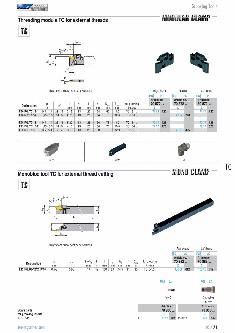
toolingcenter.com 10 / 71
10
Threading module TC for external threads
l1
h 1h 2
Tmax
f
Dmax
Illustrations show right-hand versions Right-hand Neutral Left-hand
PG 2C PG 2C PG 2CArticle no. Article no. Article no.
Designation p
1/" f h
1 l
1 h
2 D
max T
max. for grooving
inserts 70 872 ... 70 872 ... 70 872 ...
mm mm mm mm mm mm mm £ £ £E20 R/L TC 16-1 0,5 - 1,5 28 - 16 3.45 13 20 24 60 8.0 TC 16-1 ... 71.84 70872020 71.84 70872120E20 N TC 16-2 1,75 - 3,0 14 - 8 2.20 13 20 24 12.0 TC 16-2 ... 71.84 70872220 E25 R/L TC 16-1 0,5 - 1,5 28 - 16 5.20 13 25 30 75 8.0 TC 16-1 ... 72.37 70872025 72.37 70872125E25 R/L TC 16-2 1,75 - 3,0 14 - 8 4.10 13 25 30 75 10.0 TC 16-2 ... 72.37 70872225 72.37 70872325E25 N TC 16-3 3,5 - 5,0 7 - 5 3.10 13 25 30 12.0 TC 16-3 ... 72.37 70872425
66-70 89+91 93
Monobloc tool TC for external thread cutting
3
Dmax
Illustrations show right-hand versionsRight-hand Left-hand
PG 2C PG 2CArticle no. Article no.
Designation p
1/" h = h
1 b l
1 l
3 h
2 f D
max for grooving
inserts 70 882 ... 70 883 ...
mm mm mm mm mm mm mm mm £ £E12 R/L 00-1212 TC16 0,5-3 28-8 10 12 150 20 14.5 11 30 TC16-1/2.. 106.58 70882012 106.58 70883012
PG 2A PG 2A
Key D Clamping screw
Article no. Article no.Spare parts 70 950 ... 70 950 ...for grooving inserts £ £TC16-1/2.. T15 10.17 70950102 M4 x 11 8.65 70950442
Grooving Tools
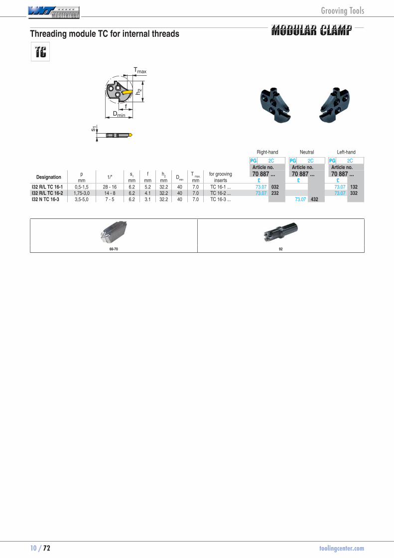
10 / 72 toolingcenter.com
Threading module TC for internal threads
h 2
Tmax
s 1
fDmin
Right-hand Neutral Left-hand
PG 2C PG 2C PG 2CArticle no. Article no. Article no.
Designation p
1/" s
1 f h
2
Dmin
T
max. for grooving
inserts 70 887 ... 70 887 ... 70 887 ...
mm mm mm mm mm £ £ £I32 R/L TC 16-1 0,5-1,5 28 - 16 6.2 5.2 32.2 40 7.0 TC 16-1 ... 73.07 70887032 73.07 70887132I32 R/L TC 16-2 1,75-3,0 14 - 8 6.2 4.1 32.2 40 7.0 TC 16-2 ... 73.07 70887232 73.07 70887332I32 N TC 16-3 3,5-5,0 7 - 5 6.2 3.1 32.2 40 7.0 TC 16-3 ... 73.07 70887432
66-70 92
Grooving Tools
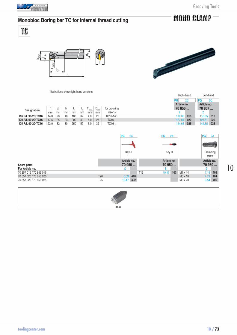
toolingcenter.com 10 / 73
10
Monobloc Boring bar TC for internal thread cutting
l1
T max
Dm
in
l2
d 1
h
f
Illustrations show right-hand versionsRight-hand Left-hand
PG 2C PG 2CArticle no. Article no.
Designation f d
1 h l
1 l
2 T
max. D
min for grooving
inserts 70 856 ... 70 857 ...
mm mm mm mm mm mm mm £ £I16 R/L 90-2D TC16 14.0 20 18 180 32 4.0 20 TC16-1/2.. 116.05 70856016 116.05 70857016I20 R/L 90-2D TC16 17.5 25 23 200 40 5.0 25 TC16-.. 127.81 70856020 127.81 70857020I25 R/L 90-2D TC16 22.0 32 30 250 50 6.0 32 TC16-.. 144.65 70856025 144.65 70857025
PG 2A PG 2A PG 2A
Key-T Key D Clamping screw
Article no. Article no. Article no.Spare parts 70 950 ... 70 950 ... 70 950 ...For Article no. £ £ £70 857 016 / 70 856 016 T15 10.17 70950102 M4 x 14 7.18 7095040370 857 020 / 70 856 020 T20 5.59 70950448 M5 x 18 4.79 7095040470 857 025 / 70 856 025 T25 10.17 70950402 M6 x 20 3.54 70950405
66-70
Grooving Tools

10 / 74 toolingcenter.com
The structure
- Strong tool holder made of 42 CrMo 4 tempered to approx. 1300 N/mm²
- Strong clamping method located by two cylindrical pins
- Clamping screw with fine thread for optimum clamping
The insert
- 3 Edges
- sintered type with inscribed circle Ø 13.2 mm
- Versions for parting, grooving, axial grooving, radius grooving, copy and precision turning
The groove
- Positive and ground cutting geometries
- extremely soft cut
- Low cutting forces
- minimum sticking
- Parting insert with chip breakers
CWX 500-Coating
The fine grain carbide grade in connection with the CWX 500 coating represents a tried and tested part of our TX side & face milling cutter programme. It is a TiALN multilayer PVD coating with the following characteristics:
- high thermal and chemical stability
- low coefficient of friction
- suitable for dry machining
- Functionality is maintained even when single layers are damaged
- small wear susceptibility
- universal application for almost all materials
Page(s) 75-77 : Grooving insert
Page(s) 78-82 : Grooving Tool holders and Boring bars
Page(s) 117 : Cutting data appoximate values
Grooving Tools
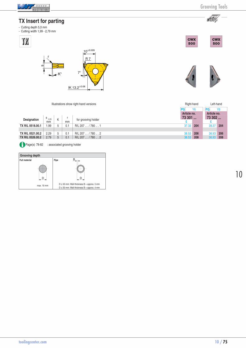
toolingcenter.com 10 / 75
10
TX Insert for parting - Cutting depth 5,0 mm - Cutting width 1,99 - 2,79 mm
IK 13.2±0.06
7°
10±0.035
R 7
s
K°
r
CWX
500
CWX
500
Illustrations show right-hand versions Right-hand Left-hand
PG Y6 PG Y6Article no. Article no.
Designation s
-0,05 K r
for grooving holder 73 301 ... 73 302 ...mm mm £ £
TX R/L 0518.00.1 1.99 5 0.1 R/L 207 .. . / 780 .. . 1 37.33 73301204 38.37 73302204 TX R/L 0521.00.2 2.29 5 0.1 R/L 207 .. . / 780 .. . 2 38.53 73301206 36.93 73302206TX R/L 0526.00.2 2.79 5 0.1 R/L 207 .. . / 780 .. . 2 38.53 73301208 36.93 73302208
Page(s) 78-82 : associated grooving holder
Grooving depth
D D
B
max. 10 mm
Full material Pipe
D ≥ 50 mm: Wall thickness B = approx. 5 mm
D ≤ 50 mm: Wall thickness B = approx. 4 mm
Grooving Tools

10 / 76 toolingcenter.com
TX insert for circlip grooves - For circlip grooves according to DIN 471 / 472
IK 13.2±0.06
7°
10±0.035
R 7
s
rαα
aa
CWX
500
Neutral
PG Y6Article no.
Designation s
2 s
-0,05 α a
+/-0,02r for grooving
holder 73 300 ...
mm mm mm mm £TX N 0050.00.1 0.50 0.57 1 0.07 0.1 R/L .. .1 25.50 73300204TX N 0060.00.1 0.60 0.67 1 0.07 0.1 R/L .. .1 25.50 73300206TX N 0070.00.1 0.70 0.77 1 0.08 0.1 R/L .. .1 25.50 73300208TX N 0080.00.1 0.80 0.87 1 0.08 0.1 R/L .. .1 25.50 73300210TX N 0090.00.1 0.90 0.97 1 0.08 0.1 R/L .. .1 25.50 73300212TX N 0100.00.1 1.00 1.07 1 0.09 0.1 R/L .. .1 25.50 73300214TX N 0110.00.1 1.10 1.24 3 0.15 0.1 R/L .. .1 25.50 73300216TX N 0130.00.1 1.30 1.44 3 0.15 0.1 R/L .. .1 25.50 73300218TX N 0160.00.1 1.60 1.74 3 0.20 0.1 R/L .. .1 25.50 73300220TX N 0185.00.1 1.85 1.99 3 0.20 0.1 R/L .. .1 25.50 73300222 TX N 0215.00.2 2.15 2.29 3 0.20 0.1 R/L .. .2 25.50 73300224TX N 0265.00.2 2.65 2.79 3 0.20 0.1 R/L .. .2 25.50 73300226 TX N 0315.00.3 3.15 3.29 3 0.20 0.1 R/L .. .3 29.09 73300228 TX N 0415.00.4 4.15 4.29 3 0.20 0.1 R/L .. .4 29.24 73300230TX N 0515.00.4 5.15 5.29 3 0.20 0.1 R/L .. .4 30.17 73300232
Page(s) 78-82 : associated grooving holder
TX insert for corner recessing - Full radius for cutting width 2,0 - 5,0 mm
IK 13.2±0.06
7°
10±0.035
s
r R 7
CWX
500
Neutral
PG Y6Article no.
Designation r s
+/-0,05T
max. D
min for grooving
holder 73 304 ...
mm mm mm mm £TX N 0010.20.2 1.0 2 0.7 22 R/L .. .2 38.71 73304204 TX N 0015.30.3 1.5 3 1.0 27 R/L .. .3 40.92 73304206 TX N 0020.40.4 2.0 4 1.2 30 R/L .. .4 40.63 73304208TX N 0025.50.4 2.5 5 1.5 35 R/L .. .4 41.32 73304210
Grooving Tools

toolingcenter.com 10 / 77
10
TX insert for fine and copy turning
rαα
s
r
IK 13.2±0.06
7°
10±0.035
R 7
CWX
500
N
PG Y6Article no.
Designation s
+0,03r
α for grooving holder 73 303 ...mm mm £
TX N 0150.02.1 1.5 0.2 3 R/L 207 .. . / 738 .. . / 660 .. . 1 31.83 73303204TX N 0200.02.1 2.0 0.2 3 R/L 207 .. . / 738 .. . / 660 .. . 1 31.83 73303206TX N 0200.04.1 2.0 0.4 3 R/L 207 .. . / 738 .. . / 660 .. . 1 32.69 73303208 TX N 0300.02.2 3.0 0.2 3 R/L 207 .. . / 738 .. . / 660 .. . 2 32.69 73303210TX N 0300.06.2 3.0 0.6 3 R/L 207 .. . / 738 .. . / 660 .. . 2 33.56 73303212TX N 0300.08.2 3.0 0.8 3 R/L 207 .. . / 738 .. . / 660 .. . 2 33.56 73303214 TX N 0400.02.3 4.0 0.2 3 R/L 207 .. . / 738 .. . / 660 .. . 3 33.85 73303216TX N 0400.08.3 4.0 0.8 3 R/L 207 .. . / 738 .. . / 660 .. . 3 33.85 73303218TX N 0400.12.3 4.0 1.2 3 R/L 207 .. . / 738 .. . / 660 .. . 3 33.85 73303220
Page(s) 78-82 : associated grooving holder
TX insert for axial grooving - Up to cutting depth 3,5 mm - Cutting width 1,5 - 5,0 mm - Groove-Ø external D
a ≥ 20 mm
s
r 0.2
IK 13.2±0.06
7°
10±0.035
a
r 0.2
b
R 7
Dmin
CWX
500
CWX
500
Illustrations show right-hand versions Right-hand Left-hand
PG Y6 PG Y6Article no. Article no.
Designation s b T
max. a D
min r for grooving
holder 73 305 ... 73 306 ...
mm mm mm mm mm mm £ £TX R/L 2015.2.2 1.5 2.7 2.0 0.2 20 0.2 R/L 207 .. . 2 36.49 73305204 36.49 73306204TX R/L 3020.2.2 2.0 2.7 3.0 0.2 30 0.2 R/L 207 .. . 2 36.49 73305206 36.49 73306206 TX R/L 3030.2.3 3.0 3.7 3.0 0.2 30 0.2 R/L 207 .. . 3 36.90 73305208 36.90 73306208 TX R/L 3040.2.4 4.0 4.3 3.5 0.2 30 0.2 R/L 207 .. . 4 37.33 73305210 37.33 73306210TX R/L 3050.2.4 5.0 5.3 3.5 0.2 30 0.2 R/L 207 .. . 4 39.03 73305212 39.03 73306212
Page(s) 78-82 : associated grooving holder
Grooving Tools

10 / 78 toolingcenter.com
Tool holder TX 0°, 6 mm cutting depth - For radial and axial grooving - Cutting width 0,5-6,3 mm
l2l1
hb
Tmax
Illustrations show right-hand versionsRight-hand Left-hand
PG Y6 PG Y6Article no. Article no.
Designation h b
+/-0,1l1 l
2 T
max. for grooving
inserts 73 500 ... 73 501 ...
mm mm mm mm mm £ £R/L 207.1212.1 12 12 100 24 4.0 TX R/N/L ...1 161.33 73500112 163.09 73501112R/L 207.1616.1 16 16 125 22 4.0 TX R/N/L ...1 143.99 73500116 145.52 73501116R/L 207.2020.1 20 20 125 21 4.0 TX R/N/L ...1 111.67 73500120 112.85 73501120R/L 207.2525.1 25 25 150 4.0 TX R/N/L ...1 117.50 73500125 118.71 73501125R/L 207.3232.1 32 32 170 4.0 TX R/N/L ...1 136.58 73500132 137.97 73501132 R/L 207.1212.2 12 12 100 24 6.0 TX R/N/L ...2 161.33 73500212 163.09 73501212R/L 207.1616.2 16 16 125 22 6.0 TX R/N/L ...2 143.99 73500216 145.52 73501216R/L 207.2020.2 20 20 125 21 6.0 TX R/N/L ...2 111.67 73500220 112.85 73501220R/L 207.2525.2 25 25 150 6.0 TX R/N/L ...2 117.50 73500225 118.71 73501225R/L 207.3232.2 32 32 170 6.0 TX R/N/L ...2 136.58 73500232 137.97 73501232 R/L 207.1212.3 12 12 100 24 6.0 TX R/N/L ...3 161.33 73500312 163.09 73501312R/L 207.1616.3 16 16 125 22 6.0 TX R/N/L ...3 143.99 73500316 145.52 73501316R/L 207.2020.3 20 20 125 21 6.0 TX R/N/L ...3 111.67 73500320 112.85 73501320R/L 207.2525.3 25 25 150 6.0 TX R/N/L ...3 117.50 73500325 118.71 73501325R/L 207.3232.3 32 32 170 6.0 TX R/N/L ...3 136.58 73500332 137.97 73501332 R/L 207.1616.4 16 16 125 22 6.0 TX R/N/L ...4 145.52 73500416 145.52 73501416R/L 207.2020.4 20 20 125 21 6.0 TX R/N/L ...4 112.85 73500420 112.85 73501420R/L 207.2525.4 25 25 150 6.0 TX R/N/L ...4 118.71 73500425 118.71 73501425R/L 207.3232.4 32 32 170 6.0 TX R/N/L ...4 137.97 73500432 137.97 73501432
Page(s) 75-77 : associated grooving insert
PG 2A PG Y6 PG Y6 PG Y6 PG Y6
Key I right hand left hand Clamping screw
Guide pin
Article no. Article no. Article no. Article no. Article no.Spare parts 70 950 ... 73 950 ... 73 950 ... 73 950 ... 73 950 ...for grooving inserts £ £ £ £ £TX R/N/L ...1 right SW03 2.05 70950176 32.81 73950020 M6 x 20 6.90 73950028 Ø 4m6 x 18 0.83 73950030TX R/N/L ...1 left SW03 2.05 70950176 32.81 73950024 M6 x 20 6.90 73950028 Ø 4m6 x 18 0.83 73950030TX R/N/L ...2 left SW03 2.05 70950176 32.81 73950024 M6 x 20 6.90 73950028 Ø 4m6 x 18 0.83 73950030TX R/N/L ...2 right SW03 2.05 70950176 32.81 73950020 M6 x 20 6.90 73950028 Ø 4m6 x 18 0.83 73950030TX R/N/L ...3 left SW03 2.05 70950176 32.81 73950024 M6 x 20 6.90 73950028 Ø 4m6 x 18 0.83 73950030TX R/N/L ...3 right SW03 2.05 70950176 32.81 73950020 M6 x 20 6.90 73950028 Ø 4m6 x 18 0.83 73950030TX R/N/L ...4 left SW03 2.05 70950176 36.44 73950026 M6 x 20 6.90 73950028 Ø 4m6 x 18 0.83 73950030TX R/N/L ...4 right SW03 2.05 70950176 36.44 73950022 M6 x 20 6.90 73950028 Ø 4m6 x 18 0.83 73950030
Grooving Tools
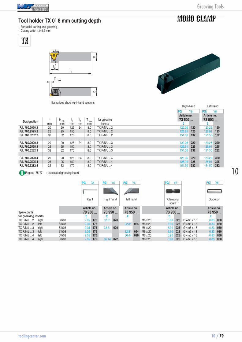
toolingcenter.com 10 / 79
10
Tool holder TX 0° 8 mm cutting depth - For radial parting and grooving - Cutting width 1,9-6,3 mm
l2l1
hb
Tmax
Illustrations show right-hand versionsRight-hand Left-hand
PG Y6 PG Y6Article no. Article no.
Designation h b
+/-0,1l1 l
2 T
max. for grooving
inserts 73 502 ... 73 503 ...
mm mm mm mm mm £ £R/L 780.2020.2 20 20 125 24 8.0 TX R/N/L ...2 120.26 73502120 120.26 73503120R/L 780.2525.2 25 25 150 8.0 TX R/N/L ...2 126.91 73502125 126.91 73503125R/L 780.3232.2 32 32 170 8.0 TX R/N/L ...2 151.50 73502132 151.50 73503132 R/L 780.2020.3 20 20 125 24 8.0 TX R/N/L ...3 120.26 73502220 120.26 73503220R/L 780.2525.3 25 25 150 8.0 TX R/N/L ...3 126.91 73502225 126.91 73503225R/L 780.3232.3 32 32 170 8.0 TX R/N/L ...3 151.50 73502232 151.50 73503232 R/L 780.2020.4 20 20 125 24 8.0 TX R/N/L ...4 120.26 73502320 120.26 73503320R/L 780.2525.4 25 25 150 8.0 TX R/N/L ...4 126.91 73502325 126.91 73503325R/L 780.3232.4 32 32 170 8.0 TX R/N/L ...4 151.50 73502332 151.50 73503332
Page(s) 75-77 : associated grooving insert
PG 2A PG Y6 PG Y6 PG Y6 PG Y6
Key I right hand left hand Clamping screw
Guide pin
Article no. Article no. Article no. Article no. Article no.Spare parts 70 950 ... 73 950 ... 73 950 ... 73 950 ... 73 950 ...for grooving inserts £ £ £ £ £TX R/N/L ...2 right SW03 2.05 70950176 32.81 73950020 M6 x 20 6.90 73950028 Ø 4m6 x 18 0.83 73950030TX R/N/L ...2 left SW03 2.05 70950176 32.81 73950024 M6 x 20 6.90 73950028 Ø 4m6 x 18 0.83 73950030TX R/N/L ...3 right SW03 2.05 70950176 32.81 73950020 M6 x 20 6.90 73950028 Ø 4m6 x 18 0.83 73950030TX R/N/L ...3 left SW03 2.05 70950176 32.81 73950024 M6 x 20 6.90 73950028 Ø 4m6 x 18 0.83 73950030TX R/N/L ...4 left SW03 2.05 70950176 36.44 73950026 M6 x 20 6.90 73950028 Ø 4m6 x 18 0.83 73950030TX R/N/L ...4 right SW03 2.05 70950176 36.44 73950022 M6 x 20 6.90 73950028 Ø 4m6 x 18 0.83 73950030
Grooving Tools

10 / 80 toolingcenter.com
Tool holder TX 90° 6 mm cutting depth - For radial grooving - Cutting width 0,5-6,3 mm
l1
hb
Tmax
l2
f
Illustrations show right-hand versionsRight-hand Left-hand
PG Y6 PG Y6Article no. Article no.
Designation h b l
1 l
2 f
+/-0,07T
max. for grooving
inserts 73 504 ... 73 505 ...
mm mm mm mm mm mm £ £R/L 738.2020.1 20 20 150 20 27 4.0 TX R/N/L ...1 140.45 73504120 140.45 73505120R/L 738.2525.1 25 25 150 32 4.0 TX R/N/L ...1 145.52 73504125 135.22 73505125 R/L 738.2020.2 20 20 150 20 27 6.0 TX R/N/L ...2 140.45 73504220 140.45 73505220R/L 738.2525.2 25 25 150 32 6.0 TX R/N/L ...2 145.52 73504225 145.52 73505225 R/L 738.2020.3 20 20 150 20 27 6.0 TX R/N/L ...3 140.45 73504320 142.92 73505320R/L 738.2525.3 25 25 150 32 6.0 TX R/N/L ...3 145.52 73504325 145.52 73505325 R/L 738.2020.4 20 20 150 20 27 6.0 TX R/N/L ...4 136.71 73504420 140.45 73505420R/L 738.2525.4 25 25 150 32 6.0 TX R/N/L ...4 145.52 73504425 145.52 73505425
Page(s) 75-77 : associated grooving insert
PG 2A PG Y6 PG Y6 PG Y6 PG Y6
Key I right hand left hand Clamping screw
Guide pin
Article no. Article no. Article no. Article no. Article no.Spare parts 70 950 ... 73 950 ... 73 950 ... 73 950 ... 73 950 ...for grooving inserts £ £ £ £ £TX R/N/L ...1 right SW03 2.05 70950176 32.81 73950020 M6 x 20 6.90 73950028 Ø 4m6 x 18 0.83 73950030TX R/N/L ...1 left SW03 2.05 70950176 32.81 73950024 M6 x 20 6.90 73950028 Ø 4m6 x 18 0.83 73950030TX R/N/L ...2 left SW03 2.05 70950176 32.81 73950024 M6 x 20 6.90 73950028 Ø 4m6 x 18 0.83 73950030TX R/N/L ...2 right SW03 2.05 70950176 32.81 73950020 M6 x 20 6.90 73950028 Ø 4m6 x 18 0.83 73950030TX R/N/L ...3 left SW03 2.05 70950176 32.81 73950024 M6 x 20 6.90 73950028 Ø 4m6 x 18 0.83 73950030TX R/N/L ...3 right SW03 2.05 70950176 32.81 73950020 M6 x 20 6.90 73950028 Ø 4m6 x 18 0.83 73950030TX R/N/L ...4 left SW03 2.05 70950176 36.44 73950026 M6 x 20 6.90 73950028 Ø 4m6 x 18 0.83 73950030TX R/N/L ...4 right SW03 2.05 70950176 36.44 73950022 M6 x 20 6.90 73950028 Ø 4m6 x 18 0.83 73950030
Grooving Tools

toolingcenter.com 10 / 81
10
Tool holder TX 45° - For recessing
1.5
l1
h
l2
b
Illustrations show right-hand versionsRight-hand Left-hand
PG Y6 PG Y6Article no. Article no.
Designation h b
+/-0,1l1 l
2 for grooving
inserts 73 506 ... 73 507 ...
mm mm mm mm £ £R/L 618.2020.2 20 20 125 30 TX R/N/L ...2 163.09 73506120 163.09 73507120R/L 618.2525.2 25 25 150 TX R/N/L ...2 170.10 73506125 170.10 73507125R/L 618.3232.2 32 32 170 TX R/N/L ...2 191.07 73506132 191.07 73507132 R/L 618.2020.3 20 20 125 30 TX R/N/L ...3 151.54 73506220 163.09 73507220R/L 618.2525.3 25 25 150 TX R/N/L ...3 170.10 73506225 170.10 73507225R/L 618.3232.3 32 32 170 TX R/N/L ...3 191.07 73506232 191.07 73507232 R/L 618.2020.4 20 20 125 30 TX R/N/L ...4 163.09 73506320 163.09 73507320R/L 618.2525.4 25 25 150 TX R/N/L ...4 170.10 73506325 170.10 73507325R/L 618.3232.4 32 32 170 TX R/N/L ...4 191.07 73506332 191.07 73507332
Page(s) 75-77 : associated grooving insert
PG 2A PG Y6 PG Y6 PG Y6 PG Y6
Key I right hand left hand Clamping screw
Guide pin
Article no. Article no. Article no. Article no. Article no.Spare parts 70 950 ... 73 950 ... 73 950 ... 73 950 ... 73 950 ...for grooving inserts £ £ £ £ £TX R/N/L ...2 right SW03 2.05 70950176 47.51 73950001 M6 x 20 6.90 73950028 Ø 4m6 x 18 0.83 73950030TX R/N/L ...2 left SW03 2.05 70950176 47.51 73950005 M6 x 20 6.90 73950028 Ø 4m6 x 18 0.83 73950030TX R/N/L ...3 right SW03 2.05 70950176 47.51 73950001 M6 x 20 6.90 73950028 Ø 4m6 x 18 0.83 73950030TX R/N/L ...3 left SW03 2.05 70950176 47.51 73950005 M6 x 20 6.90 73950028 Ø 4m6 x 18 0.83 73950030TX R/N/L ...4 left SW03 2.05 70950176 47.51 73950007 M6 x 20 6.90 73950028 Ø 4m6 x 18 0.83 73950030TX R/N/L ...4 right SW03 2.05 70950176 47.51 73950002 M6 x 20 6.90 73950028 Ø 4m6 x 18 0.83 73950030
Grooving Tools

10 / 82 toolingcenter.com
Boring bar TX - For radial internal grooving - Cutting width 0,5-6,3 mm
Dmin
l2l1
T max
d 1
Illustrations show right-hand versionsRight-hand Left-hand
PG Y6 PG Y6Article no. Article no.
Designation d
1 g7
Dmin
l1 l
2 for grooving
inserts 73 510 ... 73 511 ...
mm mm mm mm £ £R/L 660.0025.1 25 46 170 20 TX R/N/L ...1 194.60 73510125 198.42 73511125R/L 660.0032.1 32 46 200 20 TX R/N/L ...1 241.08 73510132 237.27 73511132R/L 660.0040.1 40 46 250 TX R/N/L ...1 236.62 73510140 237.27 73511140 R/L 660.0025.2 25 46 170 20 TX R/N/L ...2 194.60 73510225 194.97 73511225R/L 660.0032.2 32 46 200 20 TX R/N/L ...2 241.08 73510232 237.27 73511232R/L 660.0040.2 40 46 250 TX R/N/L ...2 236.62 73510240 237.27 73511240 R/L 660.0025.3 25 46 170 20 TX R/N/L ...3 194.60 73510325 194.97 73511325R/L 660.0032.3 32 46 200 20 TX R/N/L ...3 241.08 73510332 237.27 73511332R/L 660.0040.3 40 46 250 TX R/N/L ...3 236.62 73510340 237.27 73511340 R/L 660.0025.4 25 46 170 20 TX R/N/L ...4 194.60 73510425 194.97 73511425R/L 660.0032.4 32 46 200 20 TX R/N/L ...4 241.08 73510432 237.27 73511432R/L 660.0040.4 40 46 250 TX R/N/L ...4 236.62 73510440 237.27 73511440
Page(s) 75-77 : associated grooving insert
Bore-Ømin.
(mm) 46 50 60 80 100 for grooving insert
Tmax.
(mm)
2 3 4 4,5 5 TX R/N/L ...1
2 3 4 4,5 5 TX R/N/L ...2
2 3 4 4,5 5 TX R/N/L ...3
2 3 4 4,5 5 TX R/N/L ...4
PG Y6 PG 2A PG Y6
Clamping element
Key I Clamping screw
Article no. Article no. Article no.Spare parts 73 950 ... 70 950 ... 73 950 ...for grooving inserts £ £ £TX R/N/L ...1 40.48 73950011 SW03 2.05 70950176 M6 x 30 6.90 73950009TX R/N/L ...2 40.48 73950011 SW03 2.05 70950176 M6 x 30 6.90 73950009TX R/N/L ...3 40.48 73950011 SW03 2.05 70950176 M6 x 30 6.90 73950009TX R/N/L ...4 40.48 73950011 SW03 2.05 70950176 M6 x 30 6.90 73950009
Grooving Tools
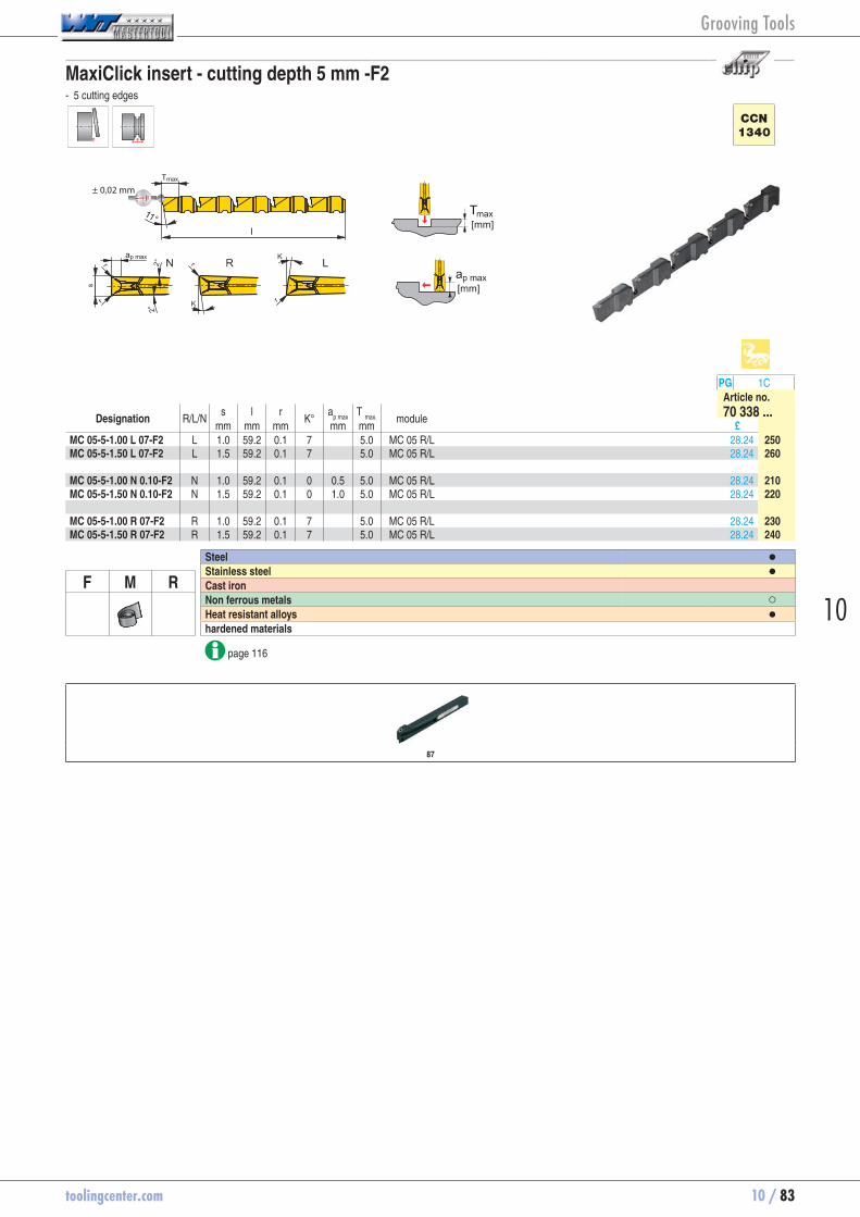
toolingcenter.com 10 / 83
10
MaxiClick insert - cutting depth 5 mm -F2 - 5 cutting edges
± 0,02 mm
CCN
1340
PG 1CArticle no.
Designation R/L/N s l r
K° a
p max T
max.
module 70 338 ...mm mm mm mm mm £
MC 05-5-1.00 L 07-F2 L 1.0 59.2 0.1 7 5.0 MC 05 R/L 28.24 70338250MC 05-5-1.50 L 07-F2 L 1.5 59.2 0.1 7 5.0 MC 05 R/L 28.24 70338260 MC 05-5-1.00 N 0.10-F2 N 1.0 59.2 0.1 0 0.5 5.0 MC 05 R/L 28.24 70338210MC 05-5-1.50 N 0.10-F2 N 1.5 59.2 0.1 0 1.0 5.0 MC 05 R/L 28.24 70338220 MC 05-5-1.00 R 07-F2 R 1.0 59.2 0.1 7 5.0 MC 05 R/L 28.24 70338230MC 05-5-1.50 R 07-F2 R 1.5 59.2 0.1 7 5.0 MC 05 R/L 28.24 70338240
Steel ●Stainless steel ●
F M R Cast iron Non ferrous metals ○Heat resistant alloys ●hardened materials
page 116
87
Grooving Tools

10 / 84 toolingcenter.com
MaxiClick insert - cutting depth 10 mm -F2 - 4 cutting edges
± 0,03 mm
CCN
1340
PG 1CArticle no.
Designation R/L/N s l r
K° a
p max T
max.
module 70 339 ...mm mm mm mm mm £
MC 10-4-1.50 L 07-F2 L 1.5 59.2 0.1 7 10.0 MC 10 R/L 23.25 70339270MC 10-4-2.00 L 07-F2 L 2.0 59.2 0.1 7 10.0 MC 10 R/L 23.25 70339280MC 10-4-2.50 L 07-F2 L 2.5 59.2 0.1 7 10.0 MC 10 R/L 23.25 70339290 MC 10-4-1.50 N 0.10-F2 N 1.5 59.2 0.1 0 1.0 10.0 MC 10 R/L 23.25 70339210MC 10-4-2.00 N 0.10-F2 N 2.0 59.2 0.1 0 1.5 10.0 MC 10 R/L 23.25 70339220MC 10-4-2.50 N 0.10-F2 N 2.5 59.2 0.1 0 2.0 10.0 MC 10 R/L 23.25 70339230 MC 10-4-1.50 R 07-F2 R 1.5 59.2 0.1 7 10.0 MC 10 R/L 23.25 70339240MC 10-4-2.00 R 07-F2 R 2.0 59.2 0.1 7 10.0 MC 10 R/L 23.25 70339250MC 10-4-2.50 R 07-F2 R 2.5 59.2 0.1 7 10.0 MC 10 R/L 23.25 70339260
Steel ●Stainless steel ●
F M R Cast iron Non ferrous metals ○Heat resistant alloys ●hardened materials
page 116
88
Grooving Tools
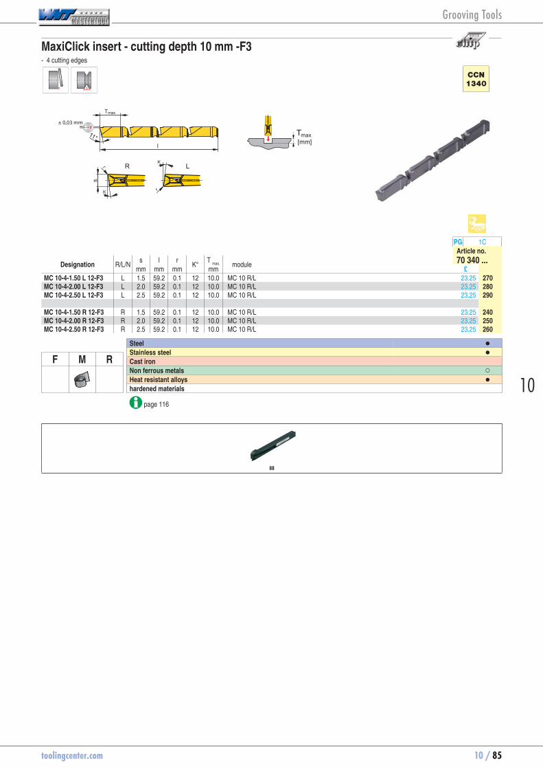
toolingcenter.com 10 / 85
10
MaxiClick insert - cutting depth 10 mm -F3 - 4 cutting edges
± 0,03 mm
CCN
1340
PG 1CArticle no.
Designation R/L/N s l r
K° T
max.
module 70 340 ...mm mm mm mm £
MC 10-4-1.50 L 12-F3 L 1.5 59.2 0.1 12 10.0 MC 10 R/L 23.25 70340270MC 10-4-2.00 L 12-F3 L 2.0 59.2 0.1 12 10.0 MC 10 R/L 23.25 70340280MC 10-4-2.50 L 12-F3 L 2.5 59.2 0.1 12 10.0 MC 10 R/L 23.25 70340290 MC 10-4-1.50 R 12-F3 R 1.5 59.2 0.1 12 10.0 MC 10 R/L 23.25 70340240MC 10-4-2.00 R 12-F3 R 2.0 59.2 0.1 12 10.0 MC 10 R/L 23.25 70340250MC 10-4-2.50 R 12-F3 R 2.5 59.2 0.1 12 10.0 MC 10 R/L 23.25 70340260
Steel ●Stainless steel ●
F M R Cast iron Non ferrous metals ○Heat resistant alloys ●hardened materials
page 116
88
Grooving Tools

10 / 86 toolingcenter.com
MaxiClick insert - cutting depth 10 mm -ALP - 4 cutting edges
± 0,03 mm
CWK
7120
PG 1CArticle no.
Designation s l r a
p max T
max.
module 70 341 ...mm mm mm mm mm £
MC 10-4-1.50 N 0.10 1.5 59.2 0.1 1.0 10.0 MC 10 R/L 19.25 70341310MC 10-4-2.00 N 0.10 2.0 59.2 0.1 1.5 10.0 MC 10 R/L 19.79 70341320MC 10-4-2.50 N 0.10 2.5 59.2 0.1 2.0 10.0 MC 10 R/L 19.79 70341330
Steel Stainless steel
F M R Cast iron Non ferrous metals ●Heat resistant alloys hardened materials
page 116
88
Grooving Tools
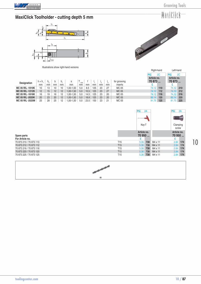
toolingcenter.com 10 / 87
10
MaxiClick Toolholder - cutting depth 5 mm
5
Illustrations show right-hand versionsRight-hand Left-hand
PG 2C PG 2CArticle no. Article no.
Designation h = h
1 h
2 b b
1 s T
max. f l
1 l
3 l
5 for grooving
inserts 70 873 ... 70 873 ...
mm mm mm mm mm mm mm mm mm mm £ £MC 05 R/L -1010K 10 13 10 10 1,00-1,50 5.0 8.5 125 23 27 MC 05 74.12 70873110 74.12 70873210MC 05 R/L -1212K 12 15 12 12 1,00-1,50 5.0 10.5 125 23 27 MC 05 74.12 70873112 74.12 70873212MC 05 R/L -1616K 16 19 16 12 1,00-1,50 5.0 14.5 125 23 20 MC 05 74.12 70873116 74.12 70873216MC 05 R/L -2020K 20 23 20 12 1,00-1,50 5.0 18.8 125 23 20 MC 05 86.14 70873120 86.14 70873220MC 05 R/L -2525M 25 28 25 12 1,00-1,50 5.0 23.5 150 23 21 MC 05 91.75 70873125 91.75 70873225
PG 2A PG 2A
Key-T Clamping screw
Article no. Article no.Spare parts 70 950 ... 70 950 ...For Article no. £ £70 873 210 / 70 873 110 T15 5.36 70950738 M4 x 11 2.84 7095017470 873 212 / 70 873 112 T15 5.36 70950738 M4 x 11 2.84 7095017470 873 216 / 70 873 116 T15 5.36 70950738 M4 x 11 2.84 7095017470 873 220 / 70 873 120 T15 5.36 70950738 M4 x 11 2.84 7095017470 873 225 / 70 873 125 T15 5.36 70950738 M4 x 11 2.84 70950174
83
Grooving Tools
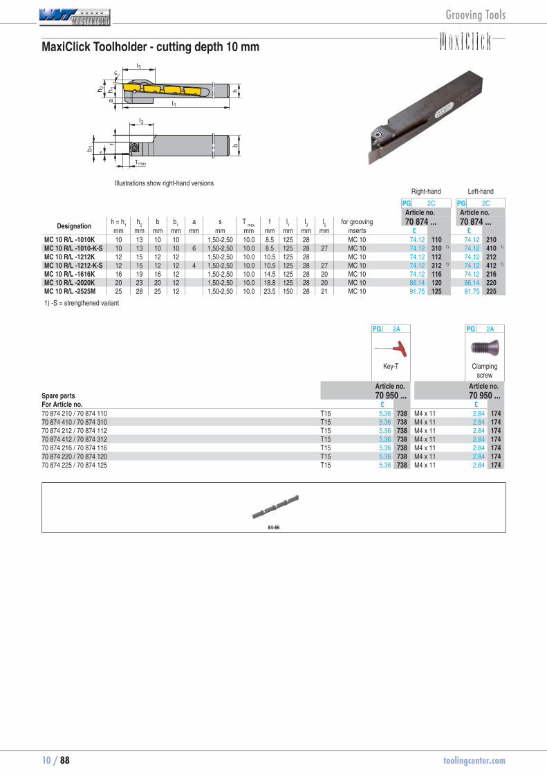
10 / 88 toolingcenter.com
MaxiClick Toolholder - cutting depth 10 mm
5
Illustrations show right-hand versionsRight-hand Left-hand
PG 2C PG 2CArticle no. Article no.
Designation h = h
1 h
2 b b
1 a s T
max. f l
1 l
3 l
5 for grooving
inserts 70 874 ... 70 874 ...
mm mm mm mm mm mm mm mm mm mm mm £ £MC 10 R/L -1010K 10 13 10 10 1,50-2,50 10.0 8.5 125 28 MC 10 74.12 70874110 74.12 70874210MC 10 R/L -1010-K-S 10 13 10 10 6 1,50-2,50 10.0 8.5 125 28 27 MC 10 74.12 70874310 1) 74.12 70874410 1)
MC 10 R/L -1212K 12 15 12 12 1,50-2,50 10.0 10.5 125 28 MC 10 74.12 70874112 74.12 70874212MC 10 R/L -1212-K-S 12 15 12 12 4 1,50-2,50 10.0 10.5 125 28 27 MC 10 74.12 70874312 1) 74.12 70874412 1)
MC 10 R/L -1616K 16 19 16 12 1,50-2,50 10.0 14.5 125 28 20 MC 10 74.12 70874116 74.12 70874216MC 10 R/L -2020K 20 23 20 12 1,50-2,50 10.0 18.8 125 28 20 MC 10 86.14 70874120 86.14 70874220MC 10 R/L -2525M 25 28 25 12 1,50-2,50 10.0 23.5 150 28 21 MC 10 91.75 70874125 91.75 70874225
1) -S = strengthened variant
PG 2A PG 2A
Key-T Clamping screw
Article no. Article no.Spare parts 70 950 ... 70 950 ...For Article no. £ £70 874 210 / 70 874 110 T15 5.36 70950738 M4 x 11 2.84 7095017470 874 410 / 70 874 310 T15 5.36 70950738 M4 x 11 2.84 7095017470 874 212 / 70 874 112 T15 5.36 70950738 M4 x 11 2.84 7095017470 874 412 / 70 874 312 T15 5.36 70950738 M4 x 11 2.84 7095017470 874 216 / 70 874 116 T15 5.36 70950738 M4 x 11 2.84 7095017470 874 220 / 70 874 120 T15 5.36 70950738 M4 x 11 2.84 7095017470 874 225 / 70 874 125 T15 5.36 70950738 M4 x 11 2.84 70950174
84-86
Grooving Tools

toolingcenter.com 10 / 89
10
Tool holder 0°
70 850 02170 851 021
Illustrations show right-hand versionsRight-hand Left-hand
PG 2C PG 2CArticle no. Article no.
Designation h = h
1 b b
1 h
2 f l
1 l
2
for modules 70 850 ... 70 851 ...mm mm mm mm mm mm mm £ £
E12 R/L 00-1212E 12 12 15.25 14.5 11.75 70 12 E12 R/L ... 109.74 70850012 109.74 70851012E16 R/L 00-1616G 16 16 19.25 19.5 15.75 90 16 E16 R/L ... 110.88 70850016 110.88 70851016E20 R/L 00-1620G 16 20 24.25 24.0 20.15 90 20 E20 R/L ... 111.84 70850021 1) 111.84 70851021 1)
E20 R/L 00-2020J 20 20 24.25 24.0 20.15 110 20 E20 R/L ... 111.84 70850020 111.84 70851020E25 R/L 00-2525L 25 25 31.00 30.0 25.50 140 25 E25 R/L ... 114.12 70850025 114.12 70851025E32 R/L 00-3225N 32 25 31.00 38.0 25.50 160 32 E32 R/L ... 117.28 70850032 117.28 70851032
1) see view A-A
PG 2A PG 2A PG 2A
Key-T Key D Clamping screw
Article no. Article no. Article no.Spare parts 70 950 ... 70 950 ... 70 950 ...For Article no. £ £ £70 851 012 / 70 850 012 T08 10.17 70950105 M2,5 x 10 5.93 7095044070 851 016 / 70 850 016 T15 10.17 70950102 M3,5 x 12,5 7.51 7095044170 851 021 / 70 850 021 T15 10.17 70950102 M4 x 14 7.18 7095040370 851 020 / 70 850 020 T15 10.17 70950102 M4 x 14 7.18 7095040370 851 025 / 70 850 025 T20 10.17 70950103 M5 x 18 4.79 7095040470 851 032 / 70 850 032 T25 10.17 70950402 M6 x 20 3.54 70950405
Module Overview
4-5
Grooving Tools

10 / 90 toolingcenter.com
Tool holder 45°
h 2
fh 1
b 1
45°
l1l2
hb
Illustrations show right-hand versionsRight-hand Left-hand
PG 2C PG 2CArticle no. Article no.
Designation h = h
1 b b
1 h
2 f l
1 l
2
for modules 70 852 ... 70 853 ...mm mm mm mm mm mm mm £ £
E20 R/L 45-2020J 20 20 21.5 24 14.5 110 20 E20 R/L ... 111.84 70852020 111.84 70853020E25 R/L 45-2525L 25 25 26.0 30 18.0 140 25 E25 R/L ... 114.12 70852025 114.12 70853025
For right hand holder → left hand module only For left hand holder → right hand module only
PG 2A PG 2A PG 2A
Key D Clamping screw
Clamping screw
Article no. Article no. Article no.Spare parts 70 950 ... 70 950 ... 70 950 ...For Article no. £ £ £70 853 020 / 70 852 020 T15 10.17 70950102 M4 x 11 8.65 70950442 M4 x 14 7.18 7095040370 853 025 / 70 852 025 T20 10.17 70950103 M5 x 13,5 9.00 70950513 M5 x 18 4.79 70950404
Module Overview
4-5
Grooving Tools
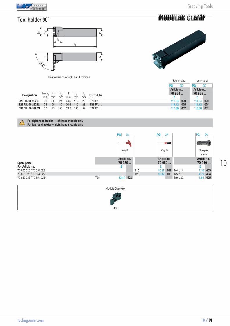
toolingcenter.com 10 / 91
10
Tool holder 90°
h 2
fh 1
l1l2
hb
90°
Illustrations show right-hand versionsRight-hand Left-hand
PG 2C PG 2CArticle no. Article no.
Designation h = h
1 b h
2 f l
1 l
2
for modules 70 854 ... 70 855 ...mm mm mm mm mm mm £ £
E20 R/L 90-2020J 20 20 24 24.5 110 20 E20 R/L ... 111.84 70854020 111.84 70855020E25 R/L 90-2525L 25 25 30 30.5 140 28 E25 R/L ... 114.12 70854025 114.12 70855025E32 R/L 90-3225N 32 25 38 39.5 160 34 E32 R/L ... 117.28 70854032 117.28 70855032
For right hand holder → left hand module only For left hand holder → right hand module only
PG 2A PG 2A PG 2A
Key-T Key D Clamping screw
Article no. Article no. Article no.Spare parts 70 950 ... 70 950 ... 70 950 ...For Article no. £ £ £70 855 020 / 70 854 020 T15 10.17 70950102 M4 x 14 7.18 7095040370 855 025 / 70 854 025 T20 10.17 70950103 M5 x 18 4.79 7095040470 855 032 / 70 854 032 T25 10.17 70950402 M6 x 20 3.54 70950405
Module Overview
4-5
Grooving Tools
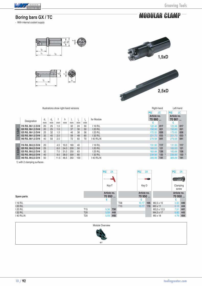
10 / 92 toolingcenter.com
Boring bars GX / TC - With internal coolant supply
l2
l1
h
d 1 f
l2l1 l3
d 1 d 2
f
Illustrations show right-hand versions Right-hand Left-hand
PG 2C PG 2CArticle no. Article no.
Designation d
1 d
2 f h l
1 l
2 l
3 for Module 70 860 ... 70 861 ...
mm mm mm mm mm mm mm £ £
≤ 1,
5xD
I16 R/L 90-1,5 D-N 20 25 1.0 32 24 50 I 16 R/L 122.46 70860017 122.46 70861017I20 R/L 90-1,5 D-N 20 25 1.0 37 30 50 I 20 R/L 150.00 70860021 150.00 70861021I25 R/L 90-1,5 D-N 25 32 1.5 46 38 56 I 25 R/L 172.02 70860026 172.02 70861026I32 R/L 90-1,5 D-N 32 40 2.0 59 48 60 I 32 R/L 221.75 70860033 1) 221.75 70861033 1)
I40 R/L 90-1,5 D-N 40 50 2.5 72 60 70 I 40 R/L/N 276.58 70860041 276.58 70861041
≤ 2,
5xD
I16 R/L 90-2,5 D-N 20 4.5 19.0 180 40 I 16 R/L 131.93 70860117 131.93 70861117I20 R/L 90-2,5 D-N 25 6.0 24.0 200 50 I 20 R/L 160.53 70860121 160.53 70861121I25 R/L 90-2,5 D-N 32 7.0 31.0 250 63 I 25 R/L 183.68 70860126 183.68 70861126I32 R/L 90-2,5 D-N 40 9.5 38.0 300 80 I 32 R/L 239.56 70860133 1) 239.56 70861133 1)
I40 R/L 90-2,5 D-N 50 11.5 48.5 350 100 I 40 R/L/N 305.09 70860141 305.09 70861141
1) with 2 clamping surfaces
PG 2A PG 2A PG 2A
Key-T Key D Clamping screw
Article no. Article no. Article no.Spare parts 70 950 ... 70 950 ... 70 950 ... £ £ £I 16 R/L T08 10.17 70950105 M2,5 x 10 5.93 70950440I 20 R/L T10 10.17 70950119 M3 x 11 6.15 70950444I 25 R/L T15 5.36 70950738 M3,5 x 12,5 7.51 70950441I 32 R/L T20 5.59 70950448 M4,5 x 17 6.82 70950445I 40 R/L/N T20 5.59 70950448 M5 x 18 4.79 70950404
Module Overview
6-7
Grooving Tools

toolingcenter.com 10 / 93
10
HSK - T Base Holder 0°
l2
l1
HS
K
d1
f
Right-hand Left-handPG 80 PG 80Article no. Article no.
ISO designation HSK l1 l
2 d
1 f
for Grooving Module 74 580 ... 74 581 ...mm mm mm mm £ £
HSK T63 E32 R/L 00 T63 74 42 53 38.7 E32 R/L... 303.13 74580532 303.13 74581532HSK T63 E25 R/L 00 T63 67 42 53 38.7 E25 R/L... 303.13 74580525 303.13 74581525HSK T100 E32 R/L 00 T100 77 45 88 48.7 E32 R/L... 346.04 74580732 346.04 74581732HSK T100 E25 R/L 00 T100 100 45 88 48.7 E25 R/L... 346.04 74580725 346.04 74581725
PG XX PG 2A PG 2A
Nozzle Key-T Clamping screw
Article no. Article no. Article no.Spare parts 70 950 ... 70 950 ... 70 950 ...For Article no. £ £ £74 581 532 / 74 580 532 15.81 70950850 10.17 70950402 3.54 7095040574 580 525 / 74 581 525 15.81 70950850 5.59 70950448 4.79 7095040474 581 732 / 74 580 732 15.81 70950850 10.17 70950402 3.54 7095040574 580 725 / 74 581 725 15.81 70950850 5.59 70950448 4.79 70950404
90° HSK - T Base Holder
l1
l2
HS
K
d1
f
90° Right-hand Left-hand
PG 80 PG 80Article no. Article no.
ISO designation HSK l1 l
2 d
1 f
for Grooving Module 74 582 ... 74 583 ...mm mm mm mm £ £
HSK T63 E32 R/L 90 T63 63.7 42 53 31.5 E32 R/L... 303.13 74582532 303.13 74583532HSK T100 E32 R/L 90 T100 73.7 45 88 50.0 E32 R/L... 346.04 74582732 346.04 74583732
PG XX PG 2A PG 2A
Nozzle Key-T Clamping screw
Article no. Article no. Article no.Spare parts 70 950 ... 70 950 ... 70 950 ...For Article no. £ £ £74 583 532 15.81 70950850 10.17 70950402 3.54 7095040574 582 532 15.81 70950850 10.17 70950402 3.54 7095040574 583 732 15.81 70950850 10.17 70950402 3.54 7095040574 582 732 15.81 70950850 10.17 70950402 3.54 70950405
Module Overview
4-5
Grooving Tools
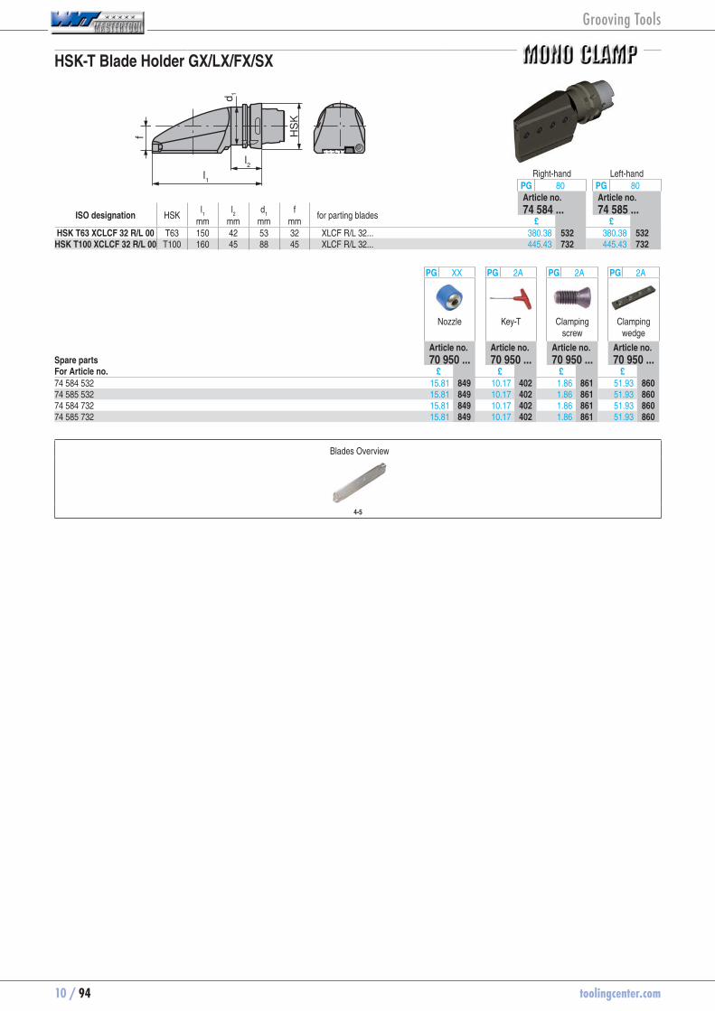
10 / 94 toolingcenter.com
HSK-T Blade Holder GX/LX/FX/SX
l1
l2
HS
K
d1
f
Right-hand Left-handPG 80 PG 80Article no. Article no.
ISO designation HSK l1 l
2 d
1 f
for parting blades 74 584 ... 74 585 ...mm mm mm mm £ £
HSK T63 XCLCF 32 R/L 00 T63 150 42 53 32 XLCF R/L 32... 380.38 74584532 380.38 74585532HSK T100 XCLCF 32 R/L 00 T100 160 45 88 45 XLCF R/L 32... 445.43 74584732 445.43 74585732
PG XX PG 2A PG 2A PG 2A
Nozzle Key-T Clamping screw
Clamping wedge
Article no. Article no. Article no. Article no.Spare parts 70 950 ... 70 950 ... 70 950 ... 70 950 ...For Article no. £ £ £ £74 584 532 15.81 70950849 10.17 70950402 1.86 70950861 51.93 7095086074 585 532 15.81 70950849 10.17 70950402 1.86 70950861 51.93 7095086074 584 732 15.81 70950849 10.17 70950402 1.86 70950861 51.93 7095086074 585 732 15.81 70950849 10.17 70950402 1.86 70950861 51.93 70950860
Blades Overview
4-5
Grooving Tools

toolingcenter.com 10 / 95
10
Clamping block for blades GX/LX/FX/SX - Supply details: split clamping block complete, but without blade and coolant set
PG 2AArticle no.
Designation h = h
1 h
2 h
3 b b
1 l
1
for blades 70 830 ...mm mm mm mm mm mm £
SBN 2020-26-K 20 26 39 20 33.0 90 XLC.N 26 .. 137.28 70830020 SBN 2520-32-K 25 32 48 20 36.0 110 XLC.N 32 .. 137.28 70830025SBN 3229-32-K 32 32 48 29 44.5 120 XLC.N 32 .. 140.35 70830032 SBN 3229-46-K 32 46 70 29 52.0 150 XLC.N 46 .. 232.28 70830132SBN 4037-46-K 40 46 70 37 60.0 150 XLC.N 46 .. 281.93 70830140
PG 2A PG 2A PG 2A
Key I Cooling agent set
clamping screw
Article no. Article no. Article no.Spare parts 70 950 ... 70 950 ... 70 950 ...For Article no. £ £ £70 830 020 SW 5 3.08 70950265 34.96 70950278 M6 x 25 1.72 7095026970 830 025 SW 5 3.08 70950265 34.96 70950278 M6 x 25 1.72 7095026970 830 032 SW 5 3.08 70950265 34.96 70950278 M6 x 25 1.72 7095026970 830 132 SW 6 4.32 70950266 34.04 70950279 M8 x 35 1.72 7095028270 830 140 SW 6 4.32 70950266 34.04 70950279 M8 x 35 1.72 70950282
Grooving Tools
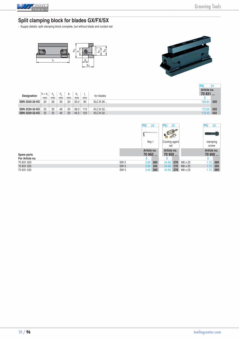
10 / 96 toolingcenter.com
Split clamping block for blades GX/FX/SX - Supply details: split clamping block complete, but without blade and coolant set
l1b1
hh 3 h 1 h 2
b
PG 2AArticle no.
Designation h = h
1 h
2 h
3 b b
1 l
1
for blades 70 831 ...mm mm mm mm mm mm £
SBN 2020-26-KS 20 26 39 20 35.0 90 XLC.N 26 .. 166.84 70831020 SBN 2520-32-KS 25 32 48 20 38.0 110 XLC.N 32 .. 172.02 70831025SBN 3229-32-KS 32 32 48 29 46.5 120 XLC.N 32 .. 178.42 70831032
PG 2A PG 2A PG 2A
Key I Cooling agent set
clamping screw
Article no. Article no. Article no.Spare parts 70 950 ... 70 950 ... 70 950 ...For Article no. £ £ £70 831 020 SW 5 3.08 70950265 34.96 70950278 M6 x 25 1.72 7095026970 831 025 SW 5 3.08 70950265 34.96 70950278 M6 x 25 1.72 7095026970 831 032 SW 5 3.08 70950265 34.96 70950278 M6 x 25 1.72 70950269
Grooving Tools

toolingcenter.com 10 / 97
10
Precision system for internal and external grooving.
The key has been designed in such a way that it will not stress the material beyond its ‘elastic limit’.
With this alternate system the material always remains in its flexible range and provides a substantial increase in tool life.
Grooving Tools
Blade max. overhang
SX 2 - SX 3 25 mm
SX 4 - SX 5 30 mm
SX 6 35 mm
Maximum blade projection when turning
The clamping
When changing the inserts, always maintain tension on the key!
Grooving Tools
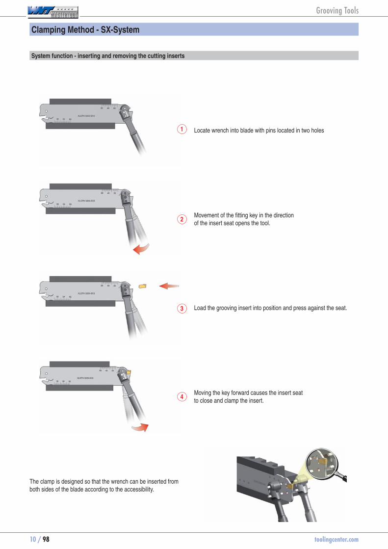
10 / 98 toolingcenter.com
Clamping Method - SX-System
System function - inserting and removing the cutting inserts
Locate wrench into blade with pins located in two holes
Movement of the fitting key in the direction of the insert seat opens the tool.
Load the grooving insert into position and press against the seat.
Moving the key forward causes the insert seat to close and clamp the insert.
The clamp is designed so that the wrench can be inserted from both sides of the blade according to the accessibility.
1
2
3
4
Grooving Tools

toolingcenter.com 10 / 99
10
Module unclamped Module clamped
- Gap between module and support face for axial clamping - Axial clamping with support face
- Connection free from play, therefore maximum stability
Gap
Gap
Clamping function - MSS Modules
Self clamping of the insert
1
32
FX SX Clamping screws 1, 2 and 3 are used for clamping the module. The insert is self-clamping.
Active insert clamping
1
32
3GX TC Clamping screws 1 and 2 are used
for clamping the module. Important: first tighten clamp screws 1 and 2. Then clamp the insert with screw 3.
Active insert clamping
4
3
12
4LX GX
AX4
Clamping screws 1, 2 and 3 are used to clamp the modules. The insert is clamped in the module via the additional screw 4.
Grooving Tools
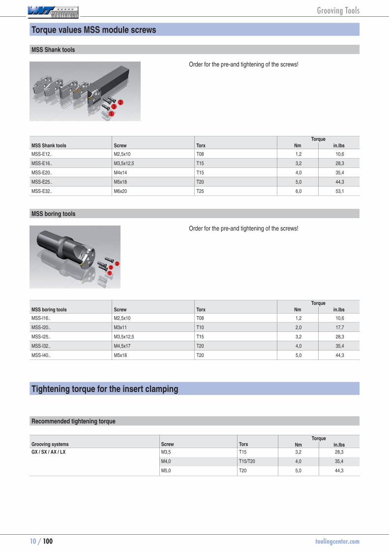
10 / 100 toolingcenter.com
Torque values MSS module screws
MSS Shank tools
Order for the pre-and tightening of the screws!
MSS Shank tools Screw TorxTorque
Nm in.lbs
MSS-E12.. M2,5x10 T08 1,2 10,6
MSS-E16.. M3,5x12,5 T15 3,2 28,3
MSS-E20.. M4x14 T15 4,0 35,4
MSS-E25.. M5x18 T20 5,0 44,3
MSS-E32.. M6x20 T25 6,0 53,1
MSS boring tools
Order for the pre-and tightening of the screws!
MSS boring tools Screw TorxTorque
Nm in.lbs
MSS-I16.. M2,5x10 T08 1,2 10,6
MSS-I20.. M3x11 T10 2,0 17,7
MSS-I25.. M3,5x12,5 T15 3,2 28,3
MSS-I32.. M4,5x17 T20 4,0 35,4
MSS-I40.. M5x18 T20 5,0 44,3
Tightening torque for the insert clamping
Recommended tightening torque
Grooving systems Screw TorxTorque
Nm in.lbs
GX / SX / AX / LX M3,5 T15 3,2 28,3
M4,0 T15/T20 4,0 35,4
M5,0 T20 5,0 44,3
Grooving Tools
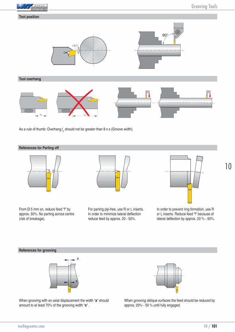
toolingcenter.com 10 / 101
10
Tool position
Tool overhang
As a rule of thumb: Overhang la should not be greater than 8 x s (Groove width).
References for Parting off
From Ø 5 mm on, reduce feed “f“ by approx. 50%. No parting across centre (risk of breakage).
For parting pip-free, use R or L inserts. In order to minimize lateral deflection reduce feed by approx. 20 - 50%.
In order to prevent ring formation, use R or L inserts. Reduce feed “f“ because of lateral deflection by approx. 20 % - 50%.
References for grooving
a
s
When grooving with an axial displacement the width “a“ should amount to at least 70% of the grooving width “s“ .
When grooving oblique surfaces the feed should be reduced by approx. 20% - 50 % until fully engaged.
Grooving Tools

10 / 102 toolingcenter.com
Grooving depth reduction
a
Size Ø0 0,5 1 1,5 2 2,5 3 3,5 4 4,5 5 5,5 6 6,5 7 7,5 8 8,5
mm mm mm mm mm mm mm mm mm mm mm mm mm mm mm mm mm mmE12 D 35 42 50 65 88 160 >160E16 D 48 55 64 77 97 135 215 >215E20 D 60 65 70 80 87 95 110 135 170 230 420 >420E25 D 82 88 95 105 115 128 145 170 210 260 350 535 1200E32 D 90 100 108 115 120 128 138 148 160 180 205 235 270 320 400 580 1000 >1000
Dm
ax a
t ful
l gr
oove
dep
th
D at reduced groove depth Tred.
Tmax
a
Ø D
Tred
Ø Dmax
Tmax
aØ DTred
Ø Dmax
a
Size Ø0 0,5 1 1,5 2 2,5 3 3,5 4
mm mm mm mm mm mm mm mm mmE32 D 90 100 108 115 120 128 138 148 160
Dm
ax a
t ful
l gr
oove
dep
th
D at reduced groove depth Tred.
The MSS grooving modules are selected by size to suit a certain work piece diameter D
max If the diameter of the
workpiece is bigger than Dmax
of the grooving module, then the achievable groove depth is reduced by dimension "a".
Tmax.
maximum grooving depth (mm)
Tred.
reduced groove depth (mm)
a Reduction amount (mm)
Dmax.
maximum workpiece Ø with at full groove depth (mm)
D Workpiece-Ø (mm)
Tred.
= Tmax.
- a
Tmax.
maximum grooving depth (mm)
Tred.
reduced groove depth (mm)
a Reduction amount (mm)
Dmax.
maximum workpiece Ø with at full groove depth (mm)
D Workpiece-Ø (mm)
Tred.
= Tmax.
- a
Grooving Tools

toolingcenter.com 10 / 103
10
Tool arrangement
Tool 0° Tool 90°
- large overhang - short overhang
- Collision danger - increased stability
- own VDI-Adaptor required - normal clamping in existing VDI adaptor possible
Grooving depth
Axial module short- clamping only on one side
- Grooving depth max. 15mm
Axial module long- can be clamped on both sides
- Grooving depth max. 21mm
Grooving Tools

10 / 104 toolingcenter.com
Feed rate guide values and information concerning machining for axial grooving and face turning GX 24 axial
Designation f (mm/U) f (mm/U) amax
(mm)
GX 24-2 E 3.00 .. 0,05 - 0,15 0,05 - 0,20 2,5GX 24-3 E 4.00 .. 0,05 - 0,15 0,05 - 0,25 3,0GX 24-3 E 5.00 .. 0,05 - 0,15 0,10 - 0,25 3,0GX 24-4 E 6.00 .. 0,05 - 0,20 0,10 - 0,30 3,5
Axial grooving Axial grooving - Groove widening Axial grooving and face turning
Is only possible with modules within the fixed diameter range (e.g. 50 - 70 mm).
In case of face turning it is possible to widen the groove above and below the diameter range indicated on the module.
Groove widening is possible above and below the diameter range indicated on the module.
Important: The indicated diameter range is always valid for the external diameter of the groove!
Important: Only the first groove must lie within the diameter range of the module. The depth of the widening groove must not be larger than the depth of the original groove.
Important: Only the first groove must lie within the diameter range of the module.
Attention: The diameter of face grooves must lie within the diameter range indicated on the module. Otherwise the tool can be damaged or destroyed.
Correct Axial grooving module Wrong Axial grooving module
smal
lest
gro
ovin
g Ø
larg
est g
roov
ing
Ø
smal
lest
gro
ovin
g Ø
larg
est g
roov
ing
Ø
smal
lest
gro
ovin
g Ø
larg
est g
roov
ing
Ø
Approximate feed rates
Grooving Tools

toolingcenter.com 10 / 105
10
Conventional
- Right-hand and left-hand version of indexable insert, therefore operation only in one direction
- For every pitch 4 threading inserts are necessary (right - left, internal - external)
- For this machining method 2 tools are required
- additional material and stability loss with large overhang
- poor accessibility
- Collision danger
- With conventional thread turning the correction of the helix angle is necessary, therefore a high degree of application know-how is required
- Can only be operated in one direction
- Neutral configuration of insert makes operation in both directions possible
- Only one threading insert per pitch for partial profile and Whitworth thread; only two threading inserts (internal - external) per pitch for ISO threads
- Reduced stock holding
- good chip formation due to chip breaker with rake angle + 10 °
Better profitability through:
- shorter operating time
- Less tool changing
- High stability wih small overhang
- Material saving
- Thread turning between shoulders
- Fewer tools and indexable inserts
- Very good access to workpiece, therefore use of tailstock also possible with small thread diameters
- Easy to apply as the tools can be used in both directions without correcting the helix angle
Advantages of TC thread turning
Overhang
Right hand threadLeft hand thread
Left hand threadRight hand thread
Right hand tools
Left hand tool
Overhang
Right hand thread Left hand thread
R =
L =
Grooving Tools
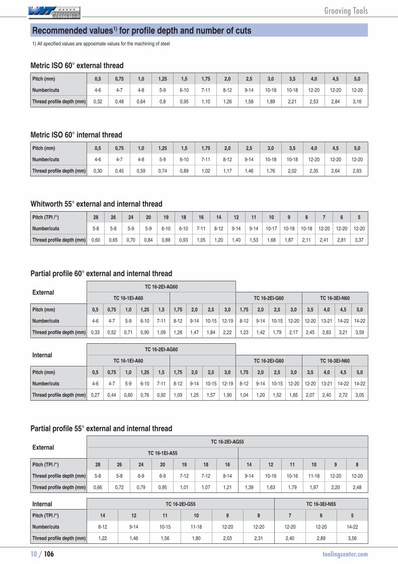
10 / 106 toolingcenter.com
Recommended values1) for profile depth and number of cuts1) All specified values are appoximate values for the machining of steel
Metric ISO 60° external thread
Pitch (mm) 0,5 0,75 1,0 1,25 1,5 1,75 2,0 2,5 3,0 3,5 4,0 4,5 5,0
Number/cuts 4-6 4-7 4-8 5-9 6-10 7-11 8-12 9-14 10-18 10-18 12-20 12-20 12-20
Thread profile depth (mm) 0,32 0,48 0,64 0,8 0,95 1,10 1,26 1,58 1,89 2,21 2,53 2,84 3,16
Metric ISO 60° internal thread
Pitch (mm) 0,5 0,75 1,0 1,25 1,5 1,75 2,0 2,5 3,0 3,5 4,0 4,5 5,0
Number/cuts 4-6 4-7 4-8 5-9 6-10 7-11 8-12 9-14 10-18 10-18 12-20 12-20 12-20
Thread profile depth (mm) 0,30 0,45 0,59 0,74 0,89 1,02 1,17 1,46 1,76 2,02 2,35 2,64 2,93
Whitworth 55° external and internal thread
Pitch (TPI /“) 28 26 24 20 19 18 16 14 12 11 10 9 8 7 6 5
Number/cuts 5-8 5-8 5-9 5-9 6-10 6-10 7-11 8-12 9-14 9-14 10-17 10-18 10-18 12-20 12-20 12-20
Thread profile depth (mm) 0,60 0,65 0,70 0,84 0,88 0,93 1,05 1,20 1,40 1,53 1,68 1,87 2,11 2,41 2,81 3,37
Partial profile 60° external and internal thread
ExternalTC 16-2EI-AG60
TC 16-1EI-A60 TC 16-2EI-G60 TC 16-3EI-N60
Pitch (mm) 0,5 0,75 1,0 1,25 1,5 1,75 2,0 2,5 3,0 1,75 2,0 2,5 3,0 3,5 4,0 4,5 5,0
Number/cuts 4-6 4-7 5-9 6-10 7-11 8-12 9-14 10-15 12-19 8-12 9-14 10-15 12-20 12-20 13-21 14-22 14-22
Thread profile depth (mm) 0,33 0,52 0,71 0,90 1,09 1,28 1,47 1,84 2,22 1,23 1,42 1,79 2,17 2,45 2,83 3,21 3,59
InternalTC 16-2EI-AG60
TC 16-1EI-A60 TC 16-2EI-G60 TC 16-3EI-N60
Pitch (mm) 0,5 0,75 1,0 1,25 1,5 1,75 2,0 2,5 3,0 1,75 2,0 2,5 3,0 3,5 4,0 4,5 5,0
Number/cuts 4-6 4-7 5-9 6-10 7-11 8-12 9-14 10-15 12-19 8-12 9-14 10-15 12-20 12-20 13-21 14-22 14-22
Thread profile depth (mm) 0,27 0,44 0,60 0,76 0,92 1,09 1,25 1,57 1,90 1,04 1,20 1,52 1,85 2,07 2,40 2,72 3,05
Partial profile 55° external and internal thread
ExternalTC 16-2EI-AG55
TC 16-1EI-A55
Pitch (TPI /“) 28 26 24 20 19 18 16 14 12 11 10 9 8
Thread profile depth (mm) 5-8 5-8 6-9 6-9 7-12 7-12 8-14 9-14 10-16 10-16 11-18 12-20 12-20
Thread profile depth (mm) 0,66 0,72 0,79 0,95 1,01 1,07 1,21 1,39 1,63 1,79 1,97 2,20 2,48
Internal TC 16-2EI-G55 TC 16-3EI-N55
Pitch (TPI /“) 14 12 11 10 9 8 7 6 5
Number/cuts 8-12 9-14 10-15 11-18 12-20 12-20 12-20 12-20 14-22
Thread profile depth (mm) 1,22 1,46 1,56 1,80 2,03 2,31 2,40 2,89 3,56
Grooving Tools
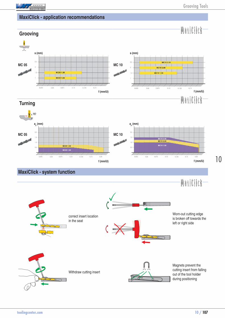
toolingcenter.com 10 / 107
10
MaxiClick - application recommendations
Grooving
MC 05 MC 10
correct insert location in the seat
Worn-out cutting edge is broken off towards the left or right side
Withdraw cutting insert
Magnets prevent the cutting insert from falling out of the tool holder during positioning
MaxiClick - system function
f (mm/U) f (mm/U)
Turning
MC 05 MC 10
f (mm/U) f (mm/U)
Grooving Tools
s (mm) s (mm)
ap (mm) a
p (mm)

10 / 108 toolingcenter.com
Wear causes
Wear on clearance face
Causes: Corrective measures:
Abrasion on the flank, normal wear after a given operation time
- cutting speed too high - grade with too low wear resistance - insufficient coolant
- Reduce the cutting speed - select a more wear resistant grade - Improve/check coolant feed
Edge chipping
Causes: Corrective measures:
Excessive mechanical stress on the cutting edge causing carbide particles to break out.
- too hard grade - vibration - too high feed and depth of cut - chip impact
- use tougher grade - use negative geometry with chip breaker - reduce overhang, check center height - stabilize the cutting edge
Cratering
Causes: Corrective measures:
The outgoing hot chip causes cratering of the insert on the clamping surface.
- too high cutting speed, feed, or both - too low rake angle - grade with too low wear resistance - incorrectly supplied cooling
- Reduce cutting speed and / or feed - Check coolant flow and / or increase pressure
- Use harder grade
Plastic deformation
Causes: Corrective measures:
Large mechanical load produces high temperature machining, this can lead to plastic deformation.
- too high operating temperature, thus softening the base material
- unsuitable grade - inadequate coolant supply
- Reduce the cutting speed - select a more wear resistant grade - use coolant
Built-up edge
Causes: Corrective measures:
Weld deposits of material on the cutting edge occurs when the chip does not flow caused by low average temperature.
- too low cutting speed - too low rake angle - Incorrect grade - lack of cooling / lubrication
- Increase the cutting speed - Increase rake angle - Use TiN coating - increase coolant strength
Notch wear
Causes: Corrective measures:
Contraction at maximum cutting depth. - Oxidation at the cutting edge - Too high a temperature at the edge
- Use different cutting depths - Reduce cutting speed - Improve/check coolant feed
Grooving Tools

toolingcenter.com 10 / 109
10
Trouble shooting guide for grooving FX/SX/GX/LX
Type of problem
Type of wear Work piece problems Swarf control
Edg
e b
reak
age
Bui
lt-up
edg
e
Wea
r on
cle
aran
ce fa
ce
Pla
stic
def
orm
atio
n
Vib
ratio
n
Form
atio
n of
pip
s an
d bu
rrs
Cha
tter
ed s
urfa
ce
Sur
face
qua
lity
Chi
p to
o lo
ng (s
narl
chi
p)
Chi
p to
o sh
ort (
frag
men
ted
chip
)Cutting speed
Cut
ting
data
Rem
edy
mea
sure
s
Feed rate
Feed rate at centre
~ ~ Chip groove
Inse
rt s
elec
tion
R/L execution
Corner radius
Grade
Groove width
~ ~ ~ ~ Tool clamping
Gen
eral
cri
teri
a~ ~ ~ ~ Work piece clamping
~ ~ Overhang
~ ~ ~ ~ ~ Tip height
Cooling lubricant
raise, increase avoid, reduce ~ check, optimiselarge influence large influence
raise, increase avoid, reduceuse
small influence small influence
wear resistance
toughness
larger
smaller
-R
-F
-M
Grooving Tools

10 / 110 toolingcenter.com
Trouble shooting guide for TC threading
Type of problem
Type of wear Workpiece Swarf control
Wea
r on
cle
aran
ce fa
ce
Bre
ak o
ut c
ut
Pla
stic
def
orm
atio
n
Bui
lt-up
edg
e
Form
atio
n of
a s
houl
der
at th
e ex
tern
al th
read
Ø
Pro
file
Sur
face
qua
lity
Cha
tter
mar
ks, v
ibra
tions
Chi
p to
o th
ick
Chi
p to
o th
in
Chi
p sh
ape
(sna
rl c
hip)
Cutting speed
Cut
ting
data
Rem
edy
mea
sure
s
a, b a, b a, b a, b a, b a, b a, b a, b Feed
~ Feed (Cutting depth)
~ ~ ~ Number of passes
Spring cut (Air cut)
Chip groove
Inde
xabl
e in
sert
sel
ectio
n
Grade
Full profile
Partial profile
~ ~ ~ Stable tool holder / insert
Vari
ous
crite
ria~ ~ ~ Stable workpiece
Overhang
~ ~ ~ ~ ~ ~ Tip height
Cooling lubricant
raise, increase avoid, reduce ~ check, optimiselarge influence large influence
raise, increase avoid, reduceuse
small influence small influence
wear resistance
toughness
over the flanks
Alternating flanks
b -
a -
Grooving Tools

toolingcenter.com 10 / 111
10
Recommended applications
-M1
FX
-M1
SX, GX
Grooving width s [mm]
Feedrate f [mm/U]
2,0 0,05 - 0,153,0 0,10 - 0,204,0 0,10 - 0,255,0 0,15 - 0,306,0 0,15 - 0,35
Grooving width s [mm]
Feedrate f [mm/U]
2,2 0,05 - 0,153,1 0,08 - 0,184,1 0,10 - 0,205,1 0,15 - 0,286,5 0,15 - 0,338,2 0,20 - 0,409,7 0,20 - 0,40
Radial grooving R/L
GX-R/L
Radius r [mm]
Feedrate f [mm/U]
0,8 0,05 - 0,101,0 - 1,2 0,05 - 0,15
Circlip grooving L / N / R
GX-L/N/R
Grooving width s [mm]
Feedrate f [mm/U]
0,60 - 1,70 0,02 - 0,091,95 - 2,25 0,05 - 0,102,75 - 3,25 0,05 - 0,124,25 0,07 - 0,155,25 0,07 - 0,17
Standard
GX
Grooving width s [mm]
Feedrate f [mm/U]
2,0 0,04 - 0,103,0 0,05 - 0,154,0 0,07 - 0,235,0 0,10 - 0,256,0 0,10 - 0,28
Dep
th o
f cut
ap [m
m]
Feedrate f [mm/U]
Grooving width s:
= 6 mm
= 5 mm
= 4 mm
= 3 mm
= 2 mm
-M2
SX, LX
Grooving width s [mm]
Feedrate f [mm/U]
2,0 0,05 - 0,153,0 0,75 - 0,204,0 0,10 - 0,255,0 0,10 - 0,306,0 0,15 - 0,358,0 0,20 - 0,5010,0 0,20 - 0,50
Dep
th o
f cut
ap [m
m]
0,05 0,15 0,25 0,350,1 0,2 0,3 0,4
0,450,5
0,5
1,0
1,5
2,0
2,5
3,0
3,5
4,0
Feedrate f [mm/U]
Grooving width s:
= 10 mm
= 8 mm
= 6 mm
= 5 mm
= 4 mm
= 3 mm
= 2 mm
When axial grooving reduce feed by 40%.
When axial grooving reduce feed by 40%.
Grooving Tools
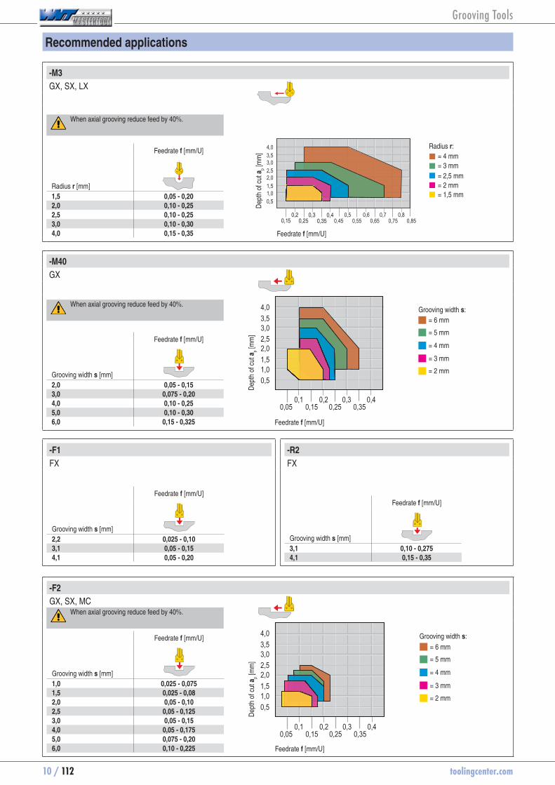
10 / 112 toolingcenter.com
-M40
GX
Grooving width s [mm]
Feedrate f [mm/U]
2,0 0,05 - 0,153,0 0,075 - 0,204,0 0,10 - 0,255,0 0,10 - 0,306,0 0,15 - 0,325
Dep
th o
f cut
ap [m
m]
0,05 0,15 0,25 0,350,1 0,2 0,3 0,4
0,5
1,0
1,5
2,0
2,5
3,0
3,5
4,0
Feedrate f [mm/U]
Grooving width s:
= 6 mm
= 5 mm
= 4 mm
= 3 mm
= 2 mm
-M3
GX, SX, LX
Radius r [mm]
Feedrate f [mm/U]
1,5 0,05 - 0,202,0 0,10 - 0,252,5 0,10 - 0,253,0 0,10 - 0,304,0 0,15 - 0,35
Dep
th o
f cut
ap [m
m]
0,450,5
0,550,6
0,650,7
0,75
0,5
1,0
1,5
2,0
2,5
3,0
3,5
4,0
0,80,85
Feedrate f [mm/U]
Radius r:
= 4 mm= 3 mm
= 2,5 mm= 2 mm= 1,5 mm
Recommended applications
-R2
FX
Grooving width s [mm]
Feedrate f [mm/U]
3,1 0,10 - 0,2754,1 0,15 - 0,35
-F1
FX
Grooving width s [mm]
Feedrate f [mm/U]
2,2 0,025 - 0,103,1 0,05 - 0,154,1 0,05 - 0,20
-F2
GX, SX, MC
Grooving width s [mm]
Feedrate f [mm/U]
1,0 0,025 - 0,0751,5 0,025 - 0,082,0 0,05 - 0,102,5 0,05 - 0,1253,0 0,05 - 0,154,0 0,05 - 0,1755,0 0,075 - 0,206,0 0,10 - 0,225
Dep
th o
f cut
ap [m
m]
0,05 0,15 0,25 0,350,1 0,2 0,3 0,4
0,5
1,0
1,5
2,0
2,5
3,0
3,5
4,0
Feedrate f [mm/U]
Grooving width s:
= 6 mm
= 5 mm
= 4 mm
= 3 mm
= 2 mm
When axial grooving reduce feed by 40%.
When axial grooving reduce feed by 40%.
When axial grooving reduce feed by 40%.
Grooving Tools

toolingcenter.com 10 / 113
10
Recommended applications
-ALP, -ALP-E
GX, SX
Grooving width s [mm]
Feedrate f [mm/U]
2,0 0,05 - 0,203,0 0,05 - 0,254,0 0,05 - 0,305,0 0,10 - 0,356,0 0,10 - 0,40
Dep
th o
f cut
ap [m
m]
0,05 0,15 0,25 0,350,1 0,2 0,3 0,4
0,51,01,52,02,53,03,54,0
Feedrate f [mm/U]
-ALP Radius
GX
Radius r [mm]
Feedrate f [mm/U]
1,5 0,05 - 0,152,0 0,075 - 0,202,5 0,10 - 0,253,0 0,10 - 0,304,0 0,15 - 0,35
Dep
th o
f cut
ap [m
m]
0,51,01,52,02,53,03,54,0
0,05 0,15 0,25 0,350,1 0,2 0,3 0,4
0,450,5
0,55 0,650,6 0,7
0,750,8
Feedrate f [mm/U]
Radius r:= 4 mm= 3 mm= 2,5 mm= 2 mm= 1,5 mm
-F50
AX
Groove width
Feedrate f [mm/U]
1. PlungingAX05 0,025 - 0,080 0,025 - 0,150AX10 0,025 - 0,065 0,025 - 0,125AX15 0,025 - 0,050 0,025 - 0,100 D
epth
of c
ut a
p [mm
]
0,05 0,15 0,25 0,350,1 0,2 0,3 0,4
0,51,01,52,02,53,03,54,0
Feedrate f [mm/U]
Grooving width s:
= AX15
= AX10
= AX05
When axial grooving reduce feed by 40%. Grooving width s:
= 6 mm
= 5 mm
= 4 mm
= 3 mm
= 2 mm
Grooving Tools

10 / 114 toolingcenter.com
Index Material Strength Material number
Material designation
Material number
Material designation
Material number
Material designation(N/mm² - HB - HRc)
A
1.1 General construction steel < 800 N/mm2 1.0037 St37-2 1.0570 St52-3 1.0060 St60-2
1.2 Free cutting steel < 800 N/mm2 1.0718 9SMnPb28 1.0727 45S20 1.0757 46SPb2
1.3 Hardened steel, non alloyed < 800 N/mm2 1.0401 C15 1.0481 17Mn4 1.1141 C15E (CK15)
1.4 Alloyed hardened steel < 1000 N/mm2 1.7331 16MnCr5 (EC80) 1.7015 13Cr3 (EC60) 1.5919 15CrNi6
1.5 Tempering steel, unalloyed < 850 N/mm2 1.0503 C45 1.1191 Ck45 1.0535 C55
1.6 Tempering steel, unalloyed < 1000 N/mm2 1.0601 C60 1.1221 Ck60 1.0540 C50
1.7 Tempering steel, alloyed < 800 N/mm2 1.5131 50MnSi4 1.7030 28Cr4 1.7225 42CrMo4
1.8 Tempering steel, alloyed < 1300 N/mm2 1.5755 31NiCr14 1.7033 34Cr4 1.3565 48CrMo4
1.9 Steel castings < 850 N/mm2 0.9650 G-X260Cr27 1.6750 GS-20NiCrMo3 7 1.6582 GS-34 CrNiMo 6
1.10 Nitriding steel < 1000 N/mm2 1.8504 34CrAl6 1.8507 34AlMo5 1.8509 41CrAlMo7
1.11 Nitriding steel < 1200 N/mm2 1.8515 31CrMo12 1.8523 39CrMoV19 3 1.8550 34 CrAlNi 7
1.12 Roller bearing steel < 1200 N/mm2 1.3505 100Cr6 (W3) 1.3543 X192CrMo17 1.3520 100 CrMn 6 (W4)
1.13 Spring steel < 1200 N/mm2 1.5026 55Si7 1.7176 55Cr3 1.7701 51CrMoV4
1.14 High-speed steel < 1300 N/mm2 1.3344 S 6-5-3 1.3255 S 18-1-2-5 1.3294 PMHS6-5-3-8; ASP30
1.15 Cold working tool steel < 1300 N/mm2 1.2312 40CrMnMoS8 6 1.2379 X155CrVMo12 1 1.2316 X38CrMo16; RAMAX
1.16 Hot working tool steel < 1300 N/mm2 1.2343 X38CrMoV 5 1 1.2767 X45NiCrMo4 1.2842 90MnCrV8
R
2.1 Steel and sulphured cast stainless steel < 850 N/mm2 1.4305 X8CrNiS18 9 1.4105 X4CrMoS18 1.4107 GX8CrNi12
2.2 Stainless steel, ferritic < 750 N/mm2 1.4510 X3CrTi17 1.4528 X10⁵CrCoMo18 2 1.4016 X6Cr17
2.3 Stainless steel, martensitic < 900 N/mm2 1.4034 X46Cr13 1.4116 X50CrMoV15 1.4106 X2CrMoSiS18-2-1
2.4 stainless steel, ferritic / martensitic <1100 N/mm2 1.4313 X3CrNi13-4 1.4028 X30Cr13 1.4104 X14CrMoS17
2.5 stainless steel, austenitic / ferritic < 850 N/mm2 1.4460 X8CrNiMo27 5 1.4821 X20CrNiSi25 4 1.4462 X2CrNiMoN22-5-3 (Duplex)
2.6 Stainless steel, austenitic < 750 N/mm2 1.4301 X5CrNi18-10 1.4571 X6CrNiMoTi17 12 2 1.4449 X3CrNiMo18-12-3
2.7 Heat resistant < 1100 N/mm2 1.4747 X80CrNiSi20 1.4876 X10NiCrAlTi32-21 1.4825 GX25CrNiSi18-9
F
3.1 Grey cast iron with lamellar graphite 100-350 N/mm2 0.6010 GG10 0.6025 GG25
3.2 Grey cast iron with lamellar graphite 300-1000 N/mm2 0.6030 GG30 0.6045 GG45
3.3 Spheroidal cast iron 300-500 N/mm2 0.7040 GGG40 0.7050 GGG50
3.4 Spheroidal cast iron 550-800 N/mm2 0.7060 GGG60 0.7080 GGG80
3.5 White malleable cast iron 350-450 N/mm2 0.8035 GTW35 0.8045 GTW45
3.6 White malleable cast iron 500-650 N/mm2 0.8055 GTW55 0.8065 GTW65
3.7 Black malleable cast iron 350-450 N/mm2 0.8135 GTS35 0.8145 GTS45
3.8 Black malleable cast iron 500-700 N/mm2 0.8155 GTS55 0.8170 GTS70
N
4.1 Aluminium (non alloyed, low alloyed) < 350 N/mm2 3.0255 Al99,5 3.3308 Al99,9Mg0,5 3.0256 E-Al H
4.2 Aluminium alloys < 0.5% Si < 500 N/mm2 3.0515 AlMn1 3.1355 AlCuMg2 3.3315 AlMg1
4.3 Aluminium alloy 0,5 - 10% Si < 400 N/mm2 3.2152 GD-AlSi6Cu4 3.2373 GD-AlSi9Mg 3.2134 GD-AlSi5Cu1Mg
4.4 Aluminium alloys 10-15% Si < 400 N/mm2 3.2381 G-AlSi10Mg 3.5562 G-MgAl6 3.2525 S-AlSi12
4.5 Aluminum alloys > 15% Si < 400 N/mm2 G-AlSi17Cu4 G-AlSi25CuNiMg G-AlSi21CuNiMg
4.6 Copper (non alloyed, low alloyed) < 350 N/mm2 2.0060 E-Cu57 2.0090 SF-Cu 2.1522 CuSl2Mn
4.7 Copper wrought alloys < 700 N/mm2 2.0240 CuZn15 2.0265 CuZn30 2.0321 CuZn37
4.8 Special copper alloys < 200 HB 2.0916 CuAl5 2.1525 CuSi3Mn Ampco 8-16
4.9 Special copper alloys < 300 HB 2.0978 CuAl11Ni6Fe5 Ampco18-26
4.10 Special copper alloys > 300 HB 2.1247 CuBe2F125 Ampco M-4
4.11 Short-chipping brass, bronze, red bronze < 600 N/mm2 2.0360 CuZn40 (Ms60) 2.0380 CuZn39Pb2 (Ms58) 2.0410 CuZn44Pb2
4.12 Long-chipping brass < 600 N/mm2 2.0335 CuZn36 (Ms63) 2.1293 CuCrZr 2.1080 CuSn6Zn6
4.13 Thermoplastics Delrin, Hostalen Makrolon, Novodur Acrylic glass
4.14 Duroplastics Ferrozell, Bakelit Pertinax Resopal
4.15 Fibre-reinforced plastics GFK* CFK** AFK***
4.16 Magnesium and magnesium alloys < 850 N/mm2 3.5200 M2, MgMn2 3.5612 MgAl6Zn1 3.5812 MgAl8Zn1
4.17 Graphite C8000, R8500X R8650 Technograph15
4.18 Tungsten and tungsten alloys W-NiFe (Densimet W) W-Cu80/20 W93NiFe (DENAL)
4.19 Molybdenum and molybdenum alloys Mo , Mo-50Re TZC, TZM MHC , ODS
S
5.1 Pure nickel 1.3911 RNi24 1.3927 RNi8 1.3926 RNi12
5.2 Nickel alloys 1.3912 Ni36 (Invar) 1.3924 Ni54 1.3921 Ni49
5.3 Nickel alloys < 850 N/mm2 2.4360 S-NiCu 30 Fe NiCu 30 Fe Monel 400
5.4 Nickel-chromium alloys 2.4886 SG-NiMo16Cr16W 2.4610 NiMo16Cr16Ti Hastelloy C-276
5.5 Nickel and cobalt alloys < 1300 N/mm2 2.4632 NiCr20Co18Ti 2.4631 NiCr20TiAl Nimonic 80
5.6 Nickel and cobalt alloys < 1300 N/mm2 2.4634 NiCo20Cr15, MoAlTi 2.4654 NiCr19Co14Mo4Ti Waspaloy
5.7 Heat resistant alloys < 1300 N/mm2 Hardox 400 1.4939 X12CrNiMo12 1.4980 X6NiCrTiMoVB25-15-2
5.8 Nickel-cobalt-chromium alloys < 1400 N/mm2 2.4806 SG-NiCr20Nb, Inconel 82 2.4851 NiCr23Fe, Inconel 601 2.4667 SG-NiCr19NbMoTi
5.9 Pure titanium < 900 N/mm2 3.7025 Ti99,8 3.7034 Ti99,7 3.7064 Ti99,5
5.10 Titanium alloys < 700 N/mm2 3.7114 TiAl5Sn2 3.7174 TiAl6V6Sn2 3.7124 TiCu2
5.11 Titanium alloys < 1200 N/mm2 3.7164 TiAl5V4 3.7144 TiAl6Sn2Zr4Mo2 3.7154 TiAl6Zr5
H
6.1
Tempered steel
< 45 HRc
6.2 46-55HRc
6.3 56-60 HRc
6.4 61-65 HRc
6.5 65-70 HRc
* Glass fibre reinforced **Carbon fibre reinforced ***Aramid fibre reinforced
Material examples referring to the WNT cutting data tables
Grooving Tools
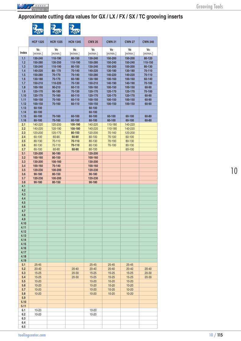
toolingcenter.com 10 / 115
10
HCF 1325 HCR 1335 HCN 1345 CWX 25 CWN 21 CWN 27 CWN 240
IndexVc
[m/min.]Vc
[m/min.]Vc
[m/min.]Vc
[m/min.]Vc
[m/min.]Vc
[m/min.]Vc
[m/min.]
1.1 130-240 110-190 80-150 130-240 150-200 150-200 80-1201.2 150-280 130-250 110-190 150-280 150-240 150-240 110-1501.3 130-240 110-190 80-150 130-240 100-200 100-200 80-1301.4 140-220 80- 170 70-140 140-220 130-180 130-180 70-1101.5 150-280 70-170 70-140 150-280 140-220 140-220 70-1101.6 130-180 70-170 60-180 130-180 100-160 100-160 60-1401.7 150-210 110-220 70-130 150-210 140-190 140-190 70-1001.8 100-160 90-210 60-110 100-160 100-150 100-150 60-901.9 120-170 90-180 70-130 120-170 120-170 120-170 70-1001.10 120-170 70-160 60-110 120-170 120-170 120-170 60-901.11 100-150 70-160 60-110 100-150 100-150 100-150 60-901.12 100-150 70-160 60-110 100-150 100-150 100-150 60-901.13 60-100 60-1001.14 60-100 60-1001.15 60-100 70-160 60-100 60-100 60-100 60-100 60-801.16 60-100 70-160 60-100 60-100 60-100 60-100 60-802.1 140-220 120-200 100-180 140-220 110-180 140-2202.2 140-220 120-190 100-180 140-220 110-180 140-2202.3 120-200 120-170 80-150 120-200 70-140 120-2002.4 60-100 60-90 60-90 60-100 70-100 60-1002.5 80-130 70-110 70-110 80-130 70-100 80-1302.6 80-130 70-110 70-110 80-130 70-100 80-1302.7 60-100 60-90 60-90 60-100 60-1003.1 120-200 90-180 120-2003.2 100-160 80-150 100-1603.3 130-200 100-160 130-2003.4 100-160 70-140 100-1603.5 120-230 100-200 120-2303.6 90-180 80-150 90-1803.7 120-230 100-200 120-2303.8 90-180 80-150 90-1804.14.24.34.44.54.64.74.84.94.104.114.124.134.144.154.164.174.184.195.1 25-45 25-45 25-45 25-455.2 20-40 20-40 20-40 20-40 20-40 20-405.3 15-25 20-30 15-25 15-25 15-25 20-305.4 15-25 20-30 15-25 15-25 15-25 20-305.5 10-20 10-20 10-20 10-205.6 10-20 10-20 10-20 10-205.7 10-20 10-20 10-20 10-205.8 10-20 10-20 10-20 10-205.95.105.116.1 10-20 10-206.2 10-20 10-206.36.46.5
Approximate cutting data values for GX / LX / FX / SX / TC grooving inserts
Grooving Tools

10 / 116 toolingcenter.com
AMZ CCN 1340 CWP 40 CWK 26 CWT 20 CWK 7120
IndexVc
[m/min.]Vc
[m/min.]Vc
[m/min.]Vc
[m/min.]Vc
[m/min.]Vc
[m/min.]
1.1 80-180 70-1501.2 110-160 120-250 100-1601.3 110-160 60-150 70-1501.4 90-130 120-200 60-1101.5 90-140 80-180 60-1101.6 80-120 60-150 60-901.7 90-130 80-180 60-1101.8 70-90 50-120 60-901.9 90-140 80-150 60-801.10 70-110 50-120 60-801.11 70-110 50-120 60-801.12 70-90 50-120 60-801.131.141.15 70-110 50-1201.16 70-110 50-1202.1 160-220 50-2002.2 160-220 50-1802.3 110-160 50-1802.4 70-110 50-802.5 50-1002.6 110-160 50-1002.7 70-110 50-803.1 180-220 110-180 100-1803.2 140-180 90-150 90-1503.3 160-200 110-180 100-1703.4 120-180 80-140 70-1303.5 180-240 100-200 90-1803.6 160-200 70-160 70-1503.7 180-240 100-200 90-803.8 160-200 70-160 70-1504.1 100-1000 100-500 100-800 100-800 100-8004.2 100-800 100-500 80-800 80-800 80-8004.3 100-500 100-500 50-500 50-500 50-5004.4 100-500 100-3004.5 100-350 100-2004.6 100-300 80-300 80-300 80-3004.7 100-300 200-600 200-600 200-6004.8 100-300 150-400 150-400 150-4004.9 100-300 150-400 150-400 150-400
4.10 100-300 150-400 150-400 150-4004.11 80-250 100-500 200-600 200-600 200-6004.12 100-370 200-600 200-600 200-6004.134.14 80-500 80-180 80-500 80-500 80-5004.15 80-200 60-150 60-150 60-150 60-1504.164.174.184.195.1 30-50 30-405.2 25-35 20-35 25-355.3 15-25 20-40 15-255.4 15-25 20-40 15-255.5 10-20 15-25 10-205.6 10-20 15-25 10-205.7 10-205.8 10-205.9 50-120 90-140 100-1405.10 30-50 30-60 40-605.11 30-50 30-60 40-606.16.26.36.46.5
Approximate cutting data values for GX / LX / FX / SX / TC grooving inserts
Grooving Tools

toolingcenter.com 10 / 117
10
CWX 500
MaterialStrength
(N/mm² - HB - HRc)Vc
[m/min.]f
Coolant[mm/U]
A
General construction steel ≤ 500 N/mm2 180 0,05 - 0,10 EmulsionGeneral construction steel 500 - 800 N/mm2 160 0,05 - 0,10 EmulsionFree cutting steel ≤ 800 N/mm2 210 0,05 - 0,12 EmulsionFree cutting steel 800 - 1000 N/mm2 180 0,05 - 0,12 EmulsionHardened steel, non alloyed ≤ 800 N/mm2 250 0,05 - 0,12 EmulsionAlloyed hardened steel 800 - 1000 N/mm2 180 0,05 - 0,10 EmulsionAlloyed hardened steel 1000 - 1200 N/mm2 140 0,05 - 0,10 EmulsionNitriding steel 800 - 1000 N/mm2 180 0,05 - 0,10 EmulsionNitriding steel 1000 - 1200 N/mm2 140 0,05 - 0,10 EmulsionTempering steel, non alloyed ≤ 800 N/mm2 210 0,05 - 0,10 EmulsionTempering steel, non alloyed 800 - 1000 N/mm2 180 0,05 - 0,10 EmulsionTempering steel, alloyed 800 - 1000 N/mm2 160 0,03 - 0,07 EmulsionTempering steel, alloyed 1000 - 1200 N/mm2 120 0,03 - 0,07 EmulsionCold working tool steel 140 0,05 - 0,10 EmulsionHot working tool steel 120 0,05 - 0,10 EmulsionHigh-speed steel 650 - 1000 N/mm2 80 0,03 - 0,07 EmulsionSpring steel ≤ 350 HB 60 0,03 - 0,07 Emulsion
RSteel and sulphured cast stainless steel ≤ 850 N/mm2 160 0,03 - 0,08 EmulsionStainless steel, ferritic ≤ 850 N/mm2 120 0,03 - 0,08 EmulsionStainless steel, martensitic ≤ 850 N/mm2 140 0,03 - 0,08 EmulsionStainless steel, austenitic ≤ 850 N/mm2 120 0,03 - 0,08 Emulsion
F
Grey cast iron ≤ 240 HB 110 0,05 - 0,10 EmulsionGrey cast iron ≤ 300 HB 95 0,05 - 0,10 EmulsionSpheroidal cast iron ≤ 240 HB 100 0,05 - 0,10 EmulsionSpheroidal cast iron ≤ 300 HB 65 0,05 - 0,10 EmulsionWhite cast iron, tempered ≤ 240 HB 110 0,05 - 0,10 EmulsionWhite cast iron, tempered ≤ 300 HB 60 0,05 - 0,10 EmulsionBlack cast iron, tempered ≤ 240 HB 110 0,05 - 0,10 EmulsionBlack cast iron, tempered ≤ 300 HB 60 0,05 - 0,10 Emulsion
N
Pure copper ≤ 400 N/mm2 180 0,05 - 0,12 PetroleumShort-chipping brass ≤ 600 N/mm2 180 0,05 - 0,12 PetroleumLong-chipping brass ≤ 600 N/mm2 160 0,05 - 0,12 PetroleumShort-chipping bronze ≤ 600 N/mm2 180 0,05 - 0,12 PetroleumShort-chipping bronze 600 - 850 N/mm2 160 0,05 - 0,12 PetroleumLong-chipping bronze ≤ 850 N/mm2 160 0,05 - 0,12 PetroleumLong-chipping bronze 850 - 1000 N/mm2 140 0,05 - 0,12 PetroleumRed bronze 160 0,05 - 0,12 PetroleumMagnesium alloys ≤ 850 N/mm2 250 0,05 - 0,12 EmulsionPure aluminium ≤ 400 N/mm2 800 0,05 - 0,12 EmulsionAluminium wrought alloys ≤ 450 N/mm2 600 0,05 - 0,12 EmulsionAlum. cast alloys < 12% Si ≤ 600 N/mm2 500 0,05 - 0,12 EmulsionAlum. cast alloys > 12% Si ≤ 600 N/mm2 600 0,05 - 0,12 EmulsionThermoplastics 120 0,05 - 0,12 EmulsionDuroplastics 180 0,05 - 0,12 EmulsionGlass/carbon fibre reinforced 80 0,05 - 0,12 EmulsionArmid fibre reinforced plastics 80 0,05 - 0,12 Emulsion
S
Heat resistant steels 50 0,03 - 0,08 EmulsionSpecial alloys ≤ 1200 N/mm2 40 0,03 - 0,08 EmulsionPure titanium ≤ 850 N/mm2 50 0,03 - 0,08 EmulsionTitanium alloys ≤ 850 N/mm2 30 0,03 - 0,08 EmulsionTitanium alloys 850 - 1200 N/mm2 30 0,03 - 0,08 Emulsion
H Tempered steel
< 45 HRc
46 - 55 HRc
56 - 60 HRc
61 - 65 HRc
65 - 70 HRc
Approximate cutting data values for TX grooving inserts
Grooving Tools